

Phone/Fax No: (818) 854- 9338/ (818) 854-9339
hereby declare s that the product
Product Name:
Model Number:
Mother Board
FCC Compliance Statement:
DECLARATION OF CONFORMITY
Per FCC Part 2 Section 2. 1077(a)
This equipment has been tested and found to
comply with limits for a Class B digital device,
Responsible Party Name: G.B.T. INC.
Address: 18305 Valley Blvd., Suite#A
LA Puent, CA 91744
pursuant to Part 15 of the FCC rules. These
limits are designed to provide reasonable
protection against harmful interference in
residential installations. This equipment
Conforms to the following specifications:
Supplementary Information:
GA- 6OMM7
FCC Part 15, Subpart B, Section 15.107(a) and Section 15.109(a),
Class B Digital Device
This device complies with part 15 of the FCC Rules. Operation is subject to the
following two conditions: (1) This device may not cause harmful
and (2) this device must accept any inference received, including
that may cause undesired operation.
Representative Person's Name: ERIC LU
Signature:
Eric Lu
Date: Jun. 13, 2000
generates, uses, and can radiate radio
frequency energy, and if not installed and used
in accordance with the instructions, may cause
harmful interference to radio communications.
However, there is no guarantee that interference
will not occur in a particular installation. If this
equipment does cause interference to radio or
television equipment reception, which can be
determined by turning the equipment off and on, the user is encouraged to try to
correct the interference by one or more of the following measures:
-Reorient or relocate the receiving antenna
-Move the equipment away from the receiver
-Plug the equipment into an outlet on a circuit different from that to which
the receiver is connected
You are cautioned that any change or modifications to the equipment not
expressly approve by the party responsible for compliance could void Your
authority to operate such equipment.
This device complies with Part 15 of the FCC Rules. Operation is subjected to
the following two conditions 1) this device may not cause harmful interference
and 2) this device must accept any interference received, including interference
that may cause undesired operation.
-Consult the dealer or an experienced radio/television technician for
additional suggestions
Declaration of Conformity
We, Manufacturer/Importer
(full address)
G.B.T. Technology Träding GMbH
Ausschlager Weg 41, 1F, 20537 Hamburg, Germany
( description of the apparatus, system, installation to which it refers)
(reference to the specification under which conformity is declared)
in accordance with 89/336 EEC-EMC Directive
EN 55011 Limits and methods of measurement EN 61000-3-2* Disturbances in supply systems caused
of radio disturbance characteristics of EN60555-2 by household appliances and similar
industrial, scientific and medical (ISM electrical equipment “Harmonics”
high frequency equipment
EN55013 Limits and methods of measurement EN61000-3-3* Disturbances in supply systems caused
of radio disturbance characteristics of EN60555-3 by household appliances and similar
broadcast receivers and associated electrical equipment “Voltage fluctuations”
equipment
EN 55014 Limits and methods of measurement EN 50081-1 Generic emission standard Part 1:
of radio disturbance characteristics of Residual, commercial and light industry
household electrical appliances,
portable tools and similar electrical EN 50082-1 Generic immunity standard Part 1:
apparatus Residual, commercial and light industry
EN 55015 Limits and methods of measurement EN 55081-2 Generic emission standard Part 2:
of radio disturbance characteristics of Industrial environment
fluorescent lamps and luminaries
EN 55020 Immunity from radio interference of EN 55082-2 Generic immunity standard Part 2:
broadcast receivers and associated Industrial environment
equipment
EN 55022 Limits and methods of measurement ENV 55104 Immunity requirements for household
of radio disturbance characteristics of appliances tools and similar apparatus
information technology equipment
DIN VDE 0855 Cabled distribution systems; Equipment EN 50091- 2 EMC requirements for uninterruptible
part 10 for receiving and/or distribution from power systems (UPS)
part 12 sound and television signals
declare that the product
Mother Board
GA-6OMM7
is in conformity with
CE marking (EC conformity marking)
The manufacturer also declares the conformity of above mentioned product
EN 60065 Safety requirements for mains operated EN 60950 Safety for information technology equipment
electronic and related apparatus for including electrical business equipment
household and similar general use
EN 60335 Safety of household and similar EN 50091-1 General and Safety requirements for
electrical appliances uninterruptible power systems (UPS)
Signature
with the actual required safety standards in accordance with LVD 73/23 EEC
Date: Jun. 13, 2000 Name : Rex Lin
(Stamp)
Manufacturer/Importer
Rex Lin
:

6OMM7
Socket 370 處理器主機板
中文安裝手冊
Socket 370 處理器主機板
REV.1.2 Second Edition

R-12-02-000727C
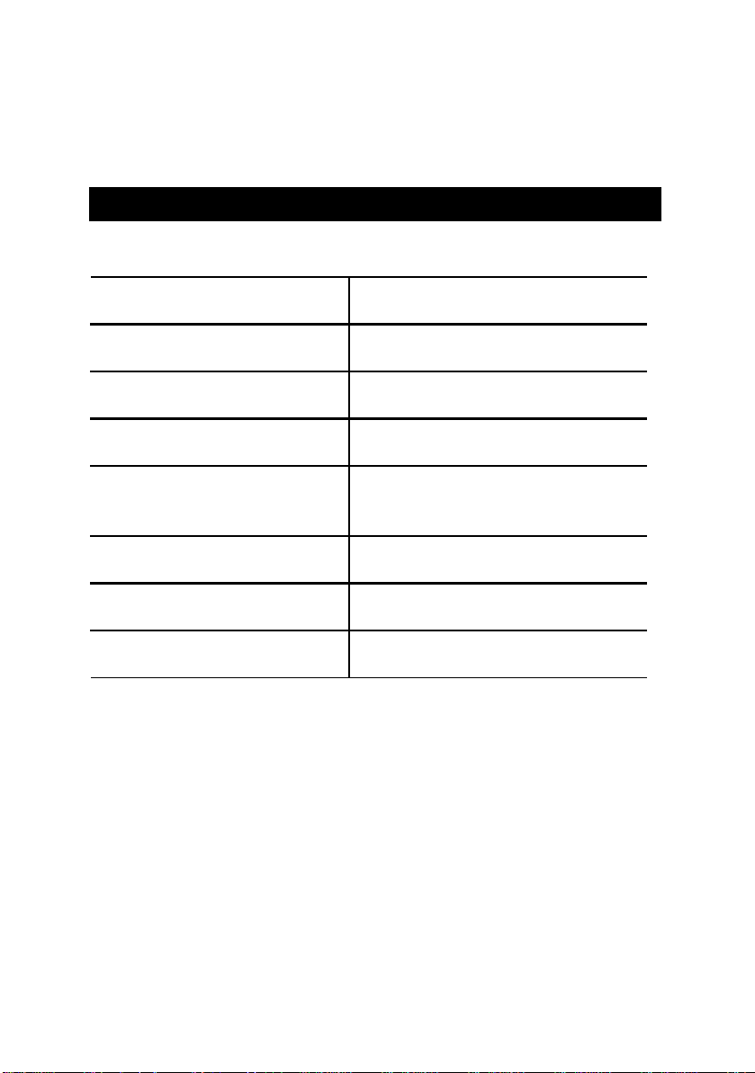
使用手冊之組織架構
此安裝手冊是依下列章節組織而成:
1) 版本修改摘要
2) 清點附件
3) 特色彙總
4) 硬體設定
5) 效能測試和晶片組功能方塊
圖
6) Suspend to RAM STR安裝說明
7) BIOS 功能設定 BIOS功能設定指南
8) 附錄
使用手冊版本修改資訊
產品盒內附件清單
主機板詳細資訊和規格
主機板安裝指南
主機板效能測試結果和晶片組功能
方塊圖
參考資料

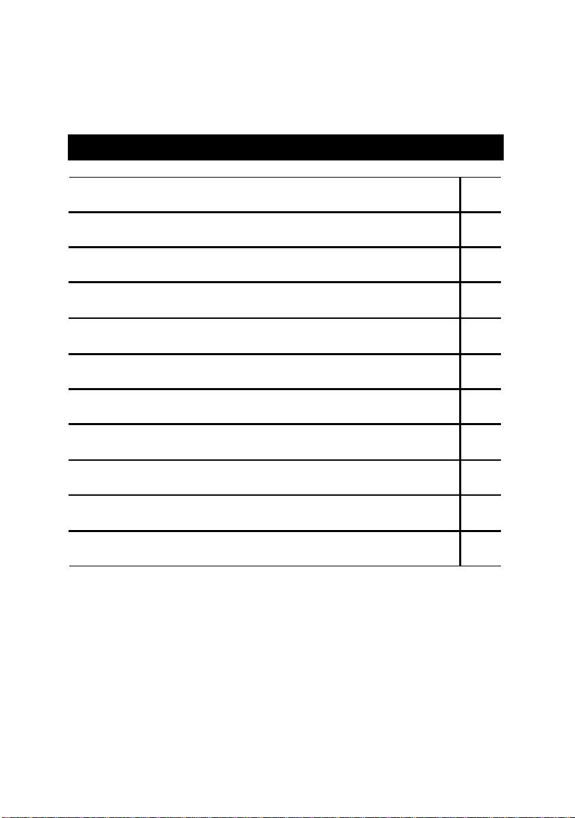
目 錄
版本修改摘要
清點附件
特色彙總
6OMM7 主機板的元件配置圖 P.5
CPU 速度設定/插座及接腳設定的快速安裝指南 P.6
效能測試
晶片組功能方塊圖
安裝Suspend to RAM 功能(選購) P.31
記憶體安裝指南
BIOS 功能設定目錄 P.38
P.1
P.2
P.3
P.29
P.30
P.37
附錄
P.72
6OMM7 主機板
版本修改摘要
版本 修改摘要 日期
1.2 6OMM7 主機板中文安裝手冊首版發行。 Jul.2000
1.2 6OMM7主機板中文安裝手冊第二版發行。 Jul.2000
本手冊所有提及之商標與名稱皆屬該公司所有。
本手冊若有任何內容修改,恕不另行通知。
2000年7月27日 台北,台灣
1

清點附件
þ6OMM7 主機板一片
þ軟、硬碟插座排線各一條
þ主機板驅動程式光碟片(IUCD)
þ6OMM7 中文使用手冊
清點附件
2
6OMM7 主機板
特色彙總
規格
Ÿ 主機板採四層設計Micro ATX規格24.4 公分x 20.5 公分
CPU Ÿ Socket 370 處理器
Intel Pentium!!! 100/133MHz FSB, FC-PGA
Intel CeleronTM 66MHz FSB, FC-PGA
nd
晶片組
時脈產生器
Ÿ 2
Ÿ Intel 815 HOST / AGP / SDRAM Controller
Ÿ 82801AA I/O Controller Hub(ICH)
Ÿ ICS 9250AF-25
Ÿ 66/100/133 MHz system bus speeds
快取記憶體取決於 CPU
記憶體 Ÿ 3 168-pin DIMM 插槽
Ÿ 支援 PC-100 / PC-133 SDRAM
Ÿ 最大支援到 512MB
Ÿ 只支援 3.3V SDRAM DIMM
I/O 控制器 Ÿ IT8712
擴充槽
內建IDE
Ÿ 1 AGP擴充槽支援4X mode 及 AGP 2.0 compliant
Ÿ 1 DFP /TV
Ÿ 3 PCI 擴充槽支援 33MHz & PCI 2.2 compliant
Ÿ 1 AMR(Audio Modem Riser) 擴充槽
Ÿ 2 IDE bus master (UDMA 33/ ATA 66) IDE 埠
可連接 4 ATAPI 裝置
Ÿ 支援 PIO mode 3, 4, UDMA33/ATA66 IDE 及ATAPI
CD-ROM
內建周邊設備 Ÿ 1 個軟碟插座支援兩台磁碟機
(360K ,720K ,1.2M ,1.44M 及 2.88M bytes )
Ÿ 1 個並列插座可支援 SPP/EPP/ECP 模式
Ÿ 1 個串列插座 (COM A)
Ÿ 2 個USB 插座
Ÿ 1 個紅外線連接端(可連接 IR/CIR )
硬體監控 Ÿ CPU/電源供應器/系統風扇轉速偵測
Ÿ CPU溫度偵測
Ÿ 系統電壓自動偵測
Ÿ CPU 過熱警報器
內建音效
Ÿ AC’97 CODEC
Ÿ Line In/Line Out/Mic In/AUX In/CD In/TEL/Game Port
續下頁…
3
PS/2 插座
BIOS Ÿ 使用經授權AWARD BIOS, 4M bit 快閃記憶體
附加特色 Ÿ 網路遠端開機功能(Wake-on-LAN)
Ÿ PS/2
Ÿ 內接型/外接型數據機開機功能
Ÿ 包含3個散熱風扇電源接腳
Ÿ 鍵盤過電流保護
鍵盤連接埠及PS/2 滑鼠連接埠
特色彙總
4
6OMM7 主機板
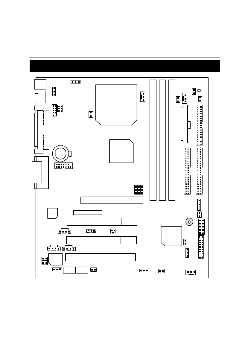
6OMM7 主機板的元件配置圖
PS/2
USB
LPT
Front USB
JP1
JP25
JP3
JP5
PGA 370
CPU
LED1
JP4
J2
JP6
J1
JP7
Floppy
ATX Power
VGA COM A
J6
JP20
JP21
6OMM7
JP23
FW82815
J13
IDE2
IDE1
JP10
JP11
JP26
DIMM2
DIMM1
JP18
JP22
DIMM3
ICH82801
BZ1
JP15
J10
JP12
JP13
JP14
J11
J14
BAT1
JP27
Game & Audio
AGP
AC’97
FWH
JP24
PCI1
PCI2
PCI3
AMR
DFP/TV
J7
J5
J12
5
6OMM7 主機板的元件配置圖
$ CPU 速度設定/插座及接腳設定的快速安裝指南
頁數
CPU 速度設定 P.8
插座
遊戲搖桿及音源插座
COM A串列插座/螢幕接頭/LPT 並列插座
P.9
P.9
P.9
USB規格插座 P.10
PS/2鍵盤及PS/2滑鼠插座
P.10
J1 (CPU散熱風扇電源接腳) P.11
J2 (電源散熱風扇電源接腳) P.11
J14 (系統散熱風扇電源接腳) P.12
ATX 電源插座
JP13 (IR/CIR) (紅外線連接端/商業用紅外線接腳)
Floppy (軟碟插座)
第一組IDE 1插座/第二組IDE 2插座
J1 3 (Ring Power On) (內建數據機喚醒功能接腳)
P.12
P.13
P.13
P.14
P.14
J12 (Wake on LAN) (網路喚醒功能接腳) P.15
J7 (TEL) (數據機內部發聲接腳) P.15
J6 (AUX_IN接腳)
J5 (光碟機音源線接腳)
JP7 (STR指示燈連接頭& LED1: DIMM LED) [選購]
USB規格插座(Front) [選購]
J10 (外部SMBUS設備接腳)
P.16
P.16
P.17
P.17
P.18
數位平面顯示器/電視輸出插座[DFP/TV Out ] P.18
JP27 (讀卡機連接頭) [SCR] P.19
接腳定義說明 P.20
J1 1 (2x11 Pins接腳)說明
JP1 8 (清除CMOS功能接腳)
JP4 (STR功能選擇接腳) [選購]
JP3 (PS/2鍵盤開機功能接腳)
JP22 (主機外殼開啟顯示接腳)
JP1 (後面板USB設備喚醒功能選擇接腳)
JP20 (BIOS寫入保護)
JP21 (Top Block Lock接腳)
JP5 (CPU電壓選擇)
JP6 (DIMM電壓選擇) [選購]
JP12 (內建蜂鳴器開關接腳) [選購]
P.20
P.21
P.21
P.22
P.22
P.23
P.23
P.24
P.24
P.25
P.25
6
6OMM7 主機板
JP14 (自動重新開機功能接腳)
P.26
7
6OMM7 主機板的元件配置圖
JP15 (系統啟動方式選擇接腳)
JP23 (PCI/AGP 3VAUX) P.27
JP24 (AMR 選擇接腳) [選購]
JP25 (USB 規格插座選擇接腳) [選購] P.28
P.26
P.27
8
CPU 速度設定
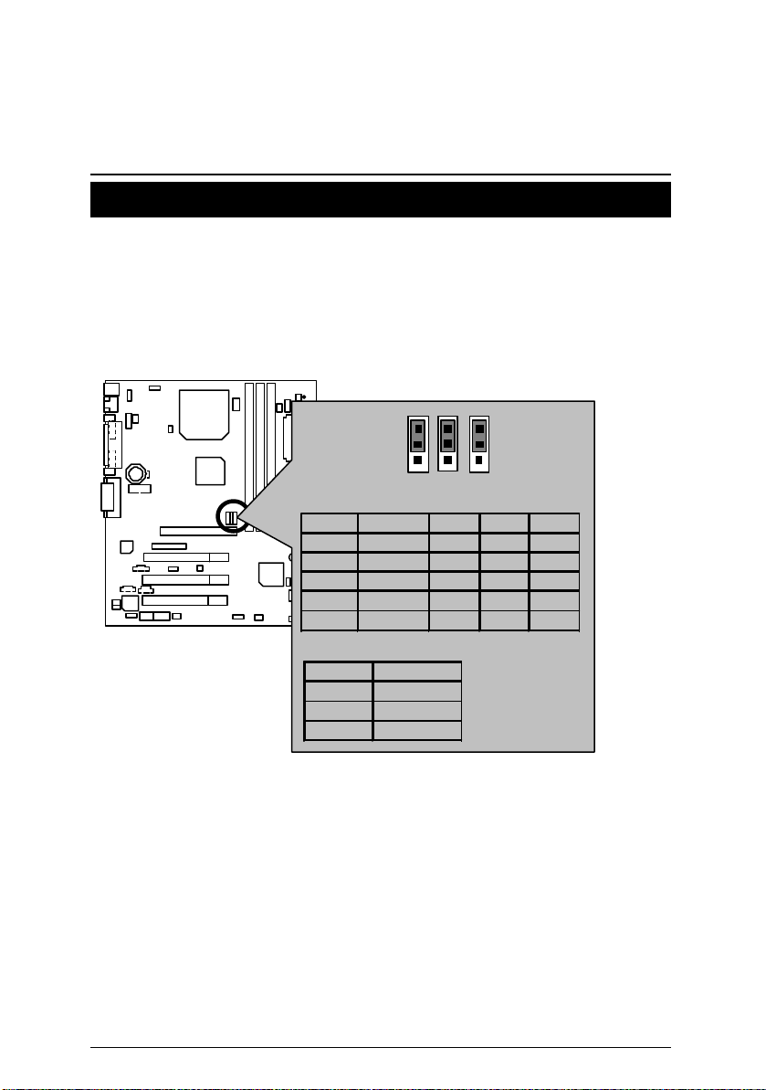
CPU速度設定
您可以利用JP10/JP11 及JP26(見圖1)來做系統外頻切換, 選擇 100MHz 及 133MHz 或
Auto. CPU倍頻由 BIOS自動去偵測控制.
M
請注意主機板上設定的倍頻及外頻,需要和CPU的倍頻及外頻相符合,否則易
造成系統當機。
JP10/JP11/JP26: CPU速度設定 (選購)
JP10
1
1
1
JP26
JP11
CPU SDRAM JP10 JP11 JP26
Auto Auto 1-2 1-2 1-2
66 100 2-3 2-3 1-2
100 100 2-3 Open 1-2
133 133 Open 2-3 1-2
133 100 Open Open 2-3
自動組態設定:
CPU SDRAM
66 100
100 100
133
Ö
133/100
圖 1
Ö 若您的 CPU 外頻為133 MHz, BIOS 會自動偵測 SDRAM的 SPD值, 判斷Memory 的
最佳執行頻率。
M 若您的主機板上無JP10,JP11及JP26接腳,系統外頻將由BIOS自動偵測.若是此3
個接腳有效存在,您可作 66MHz, 100MHz, 133MHz 或 Auto的頻率選擇。
M請依據您CPU的規格來設定CPU 的頻率,我們不建議您將系統速度設定超過硬
體之標準範圍,因為這些規格對於周邊設備而言並不算是符合標準規格。如果您
要將系統速度設定超出標準規格,請依據您的硬體規格設定,例如;CPU,顯示卡,
記憶體,硬碟來設定。
9
6OMM7 主機板
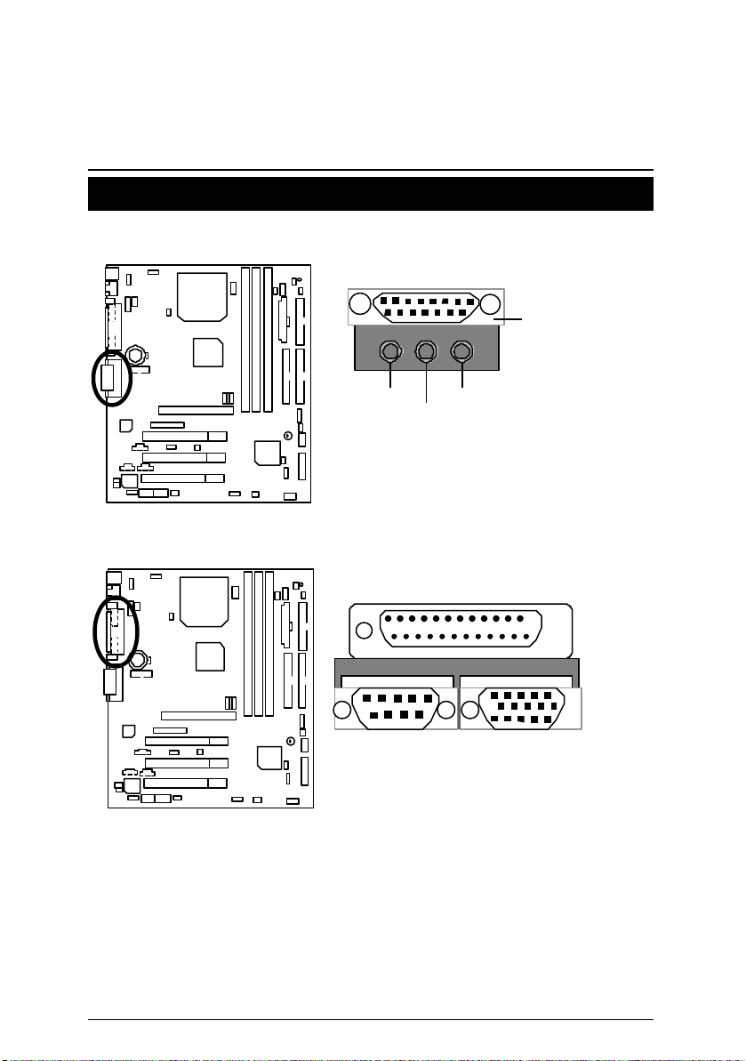
插座
遊戲搖桿及音源插座
Game
Port
Line Out
Line In
COM A串列插座/螢幕接頭/LPT並列插座
LPT Port
COM A
MIC In
VGA
10
6OMM7 主機板
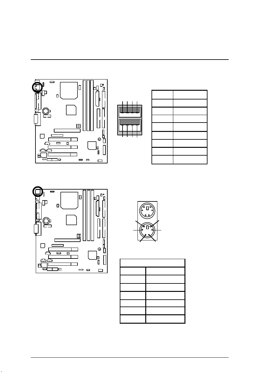
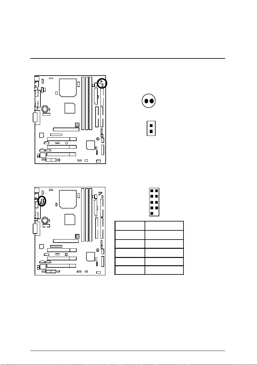
USB規格插座
PS/2鍵盤及 PS/2滑鼠插座
8 7 6 5
1 2 3 4
PS/2
6
4
接腳 定義
滑鼠
1 2
PS/2 鍵盤
滑鼠/鍵盤
PS/2
接腳
1
2
3
4 VCC (+5V)
5
6
資料訊號線
無作用
接地線
無作用
1 USB V0
2 USB D03 USB D0+
4 接地線
5 USB V1
6 USB D17 USB D1+
8 接地線
5
3
定義
時脈
11
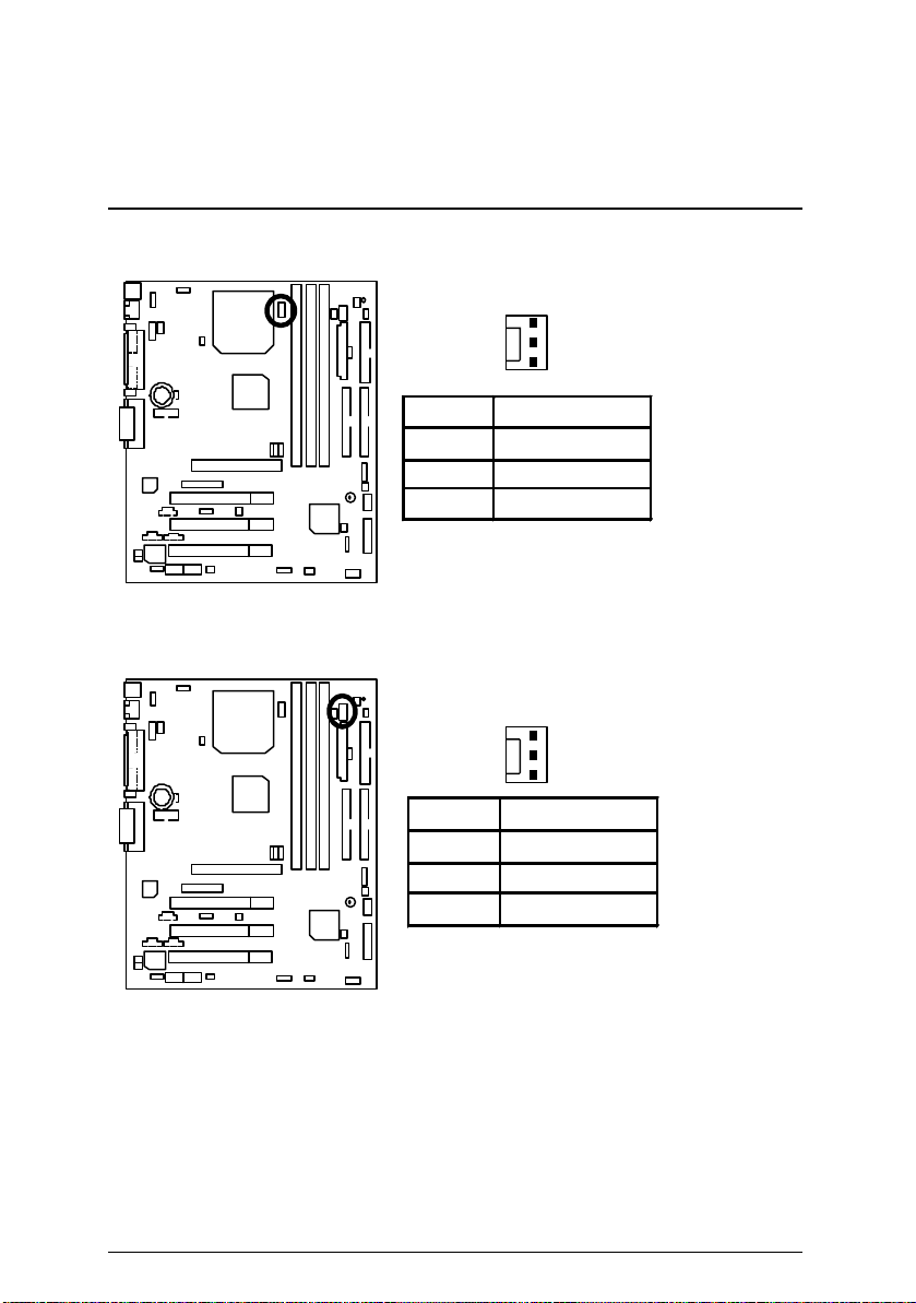
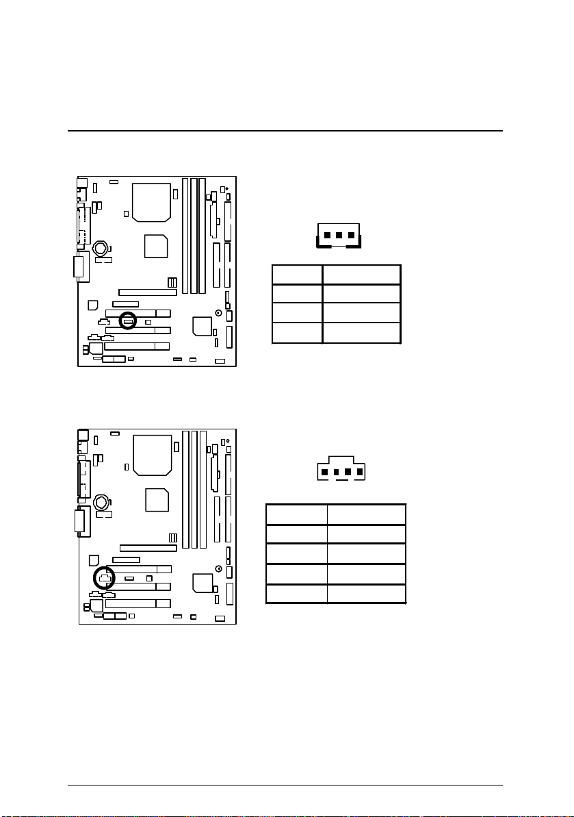
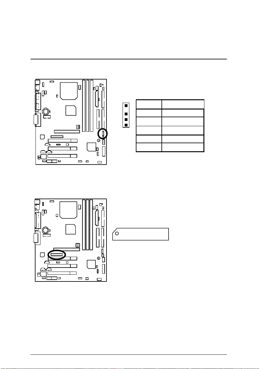
J1: CPU 散熱風扇電源接腳
J2: 電源散熱風扇電源接腳
插座及接腳設定的快速安裝指南
1
接腳 定義
1 風扇運轉控制
2 +12V
3 偵測訊號線
1
接腳 定義
1 風扇運轉控制
2 +12V
3 偵測訊號線
12
6OMM7 主機板
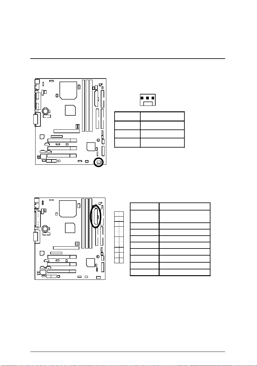
J14: 系統散熱風扇電源接腳
1
接腳 定義
1 風扇運轉控制
2 +12V
3 偵測訊號線
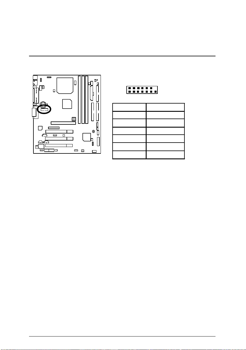
ATX電源插座
接腳
10
20
3,5,7,13,
15-17
定義
接地線
1,2,11 3.3V
4,6,19,20 VCC
10 +12V
12 -12V
18 -5V
11
1
8
電源良好訊號
9 5V SB stand by+5V
14 PS-ON(Soft On/Off)
13
插座及接腳設定的快速安裝指南
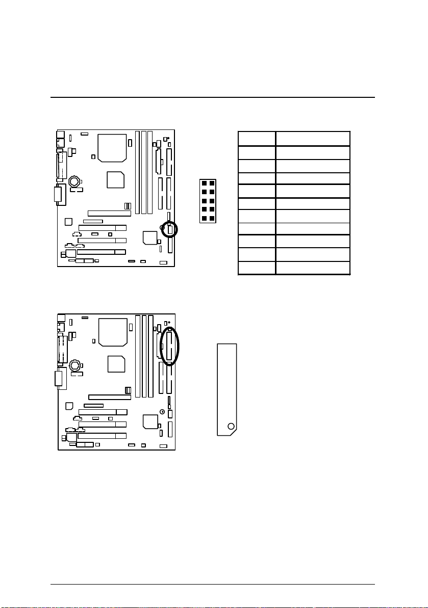
JP13: IR/CIR(紅外線連接端/商業用紅外線接腳)
1
5 6 10
接腳
1
2
3 IRRX
4
5 IRTX
6
7 CIRRX
8
9
10
Floppy: 軟碟插座
定義
電源線
無作用
接地線
無作用
電源線
無作用
無作用
紅色線
14
6OMM7 主機板
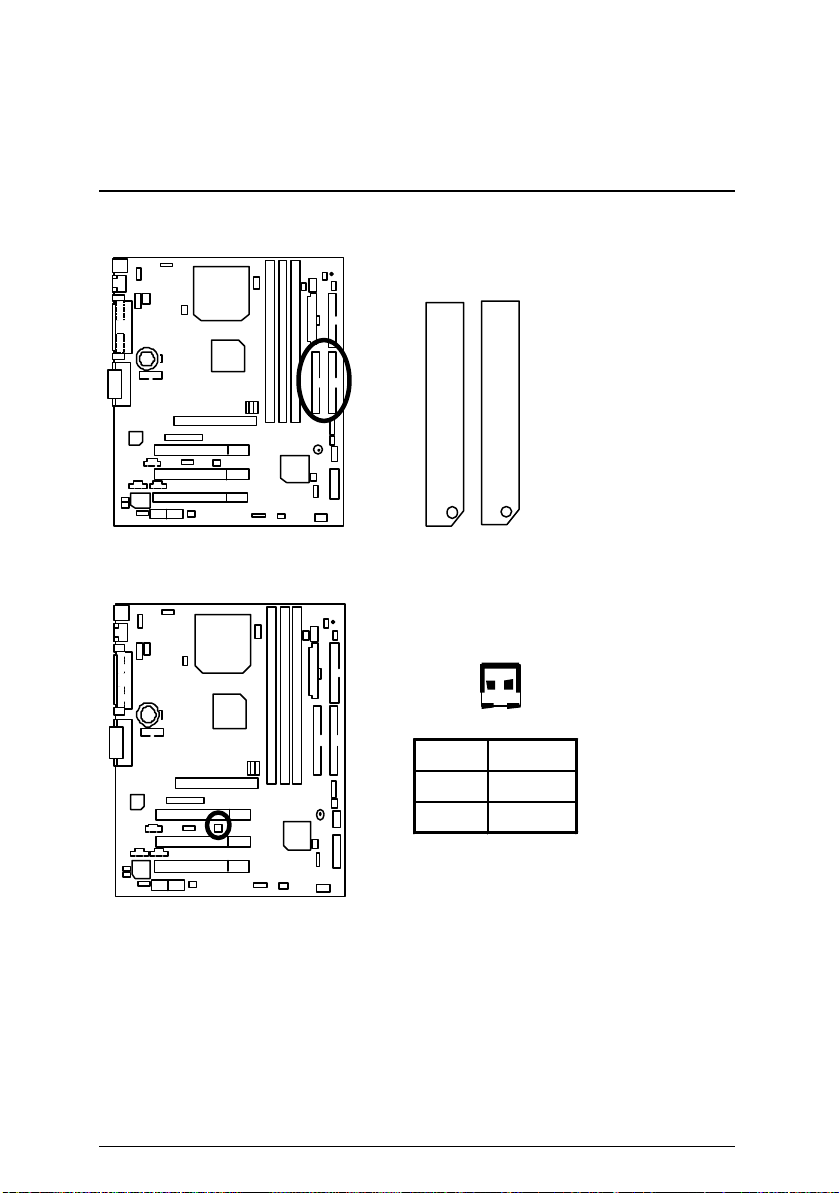
第一組IDE 1插座 / 第二組IDE 2插座
IDE 2 IDE 1
紅色線
J13: Ring Power On (內建數據機喚醒功能接腳)
1
接腳 定義
訊號線
1
接地線
2
15
J12: Wake On LAN (網路喚醒功能接腳)
1
接腳 定義
1 +5V SB
2 接地線
3 訊號線
插座及接腳設定的快速安裝指南
J7: TEL: 數據機內部發聲接腳
1
接腳 定義
1 Signal-In
2 接地線
3 接地線
4 Signal-Out
16
6OMM7 主機板
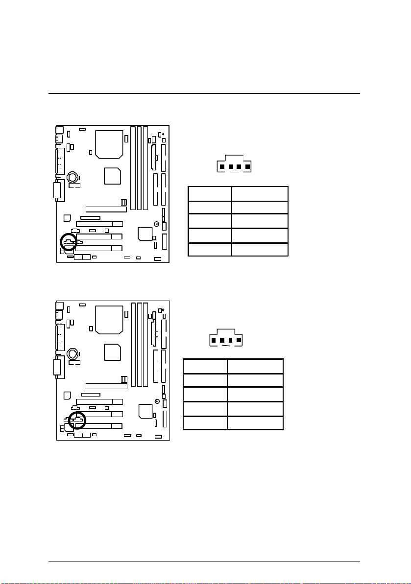
J6: AUX_IN 接腳
接腳 定義
1 AUX-L
2 接地線
3 接地線
4 AUX-R
J5: CD Audio Line In (光碟機音源線接腳)
1
接腳 定義
1 CD-L
2 接地線
3 接地線
4 CD-R
1
17

插座及接腳設定的快速安裝指南
18
6OMM7 主機板
+
JP7: STR 指示燈接腳及 LED1: DIMM 指示燈(選購)
DIMM 指示燈
1
指示燈外部接腳
STR
USB規格插座(Front) [選購]
接腳 定義
1,4,5,10 無作用
3,7,9 接地線
1
2
9
10
2 +5V
6 USBP0+
8 USBP0-
19
J10 : 外部SMBUS設備接腳
插座及接腳設定的快速安裝指南
1
接腳 定義
1 SMB CLK
2 無作用
3
接地線
4 SMB DATA
5 +5V
數位平面顯示器/電視輸出插座(DFP/TV Out)
僅支援技嘉 Digital Flat Panel/TV -Out子卡(GA-DFP-x).
í
1
2
27
28
20
6OMM7 主機板
JP27: SCR: 讀卡機連接頭
2
14
1
接腳
13
定義
1 VCC
2,3,4,8,13 無作用
5,6,10,12 DATA
7 Clock
9,14 無作用
11 接地線
21
插座及接腳設定的快速安裝指南
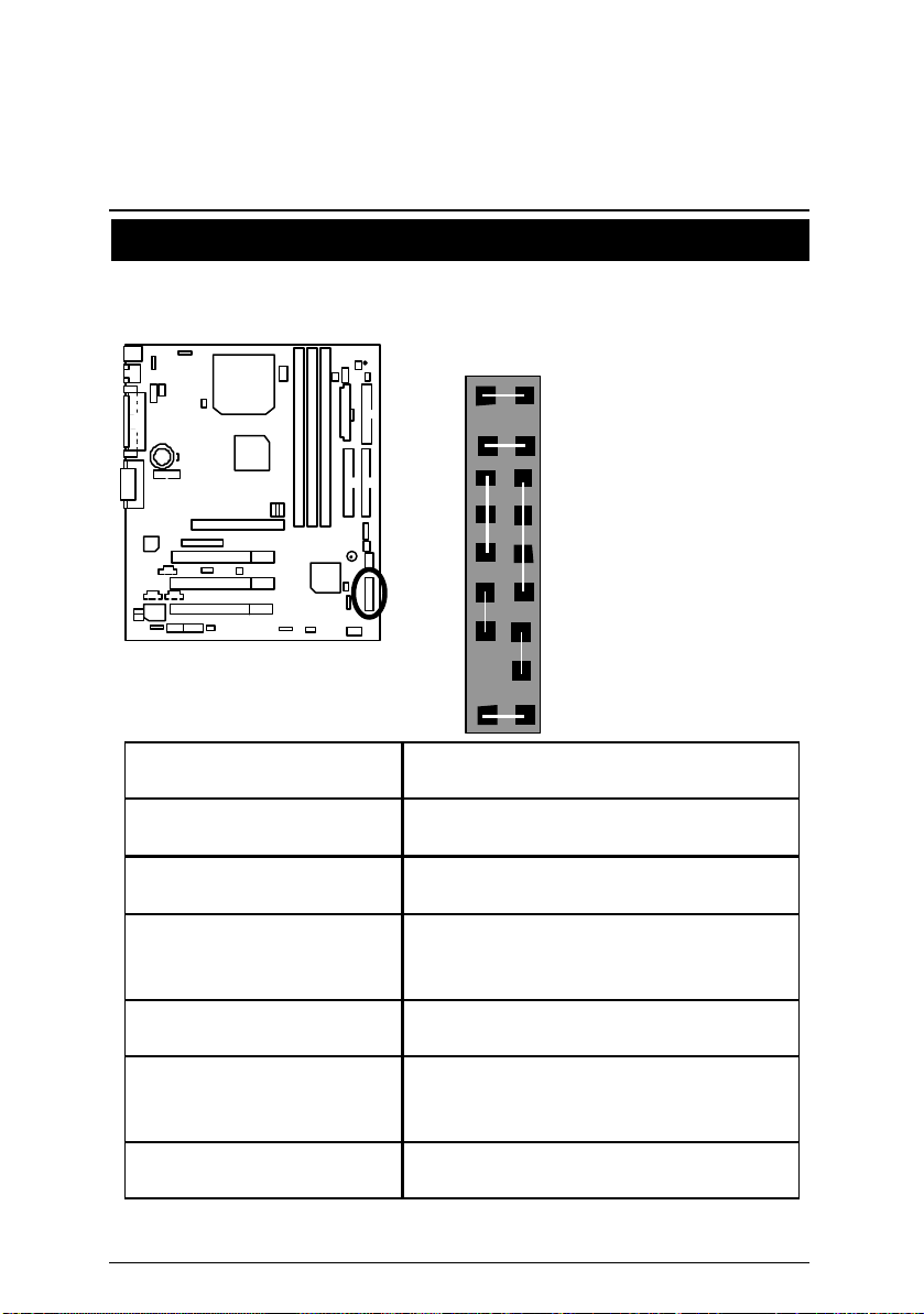
接腳定義說明
J11: For 2x11 Pins 接腳說明
GN : 省電模式開關
(Green Switch)
GD: 省電模式指示燈
(Green LED)
HD: 硬碟存取指示燈接頭
(IDE Hard Disk Active LED)
SPK: 內建蜂鳴器
(Speaker Connector)
RE: 重置開關接頭
(Reset Switch)
P+P−P−: 電源指示燈
(Power LED)
PW : 按鍵開/關機
(Soft Power Connector)
1
GN
1
HD
1
PW P+ P− P−
GD
開路: 一般運作
短路: 進入省電模式
接腳 1: LED 燈號正極(+)
接腳 2: LED 燈號負極(−)
接腳 1: LED 燈號正極(+)
接腳 2: LED 燈號負極(−)
接腳 1: 電源線VCC(+)
接腳 2- 接腳 3: 無作用
接腳 4: 資料輸出線(−)
開路: 一般運作
短路: 強迫系統重新開機
接腳 1: LED 燈號正極(+)
接腳 2: LED 燈號負極(−)
接腳 3: LED 燈號負極(−)
開路: 一般運作
短路: 啟動電源開關
S P K
1
RE
1
22
 Loading...