


Gigabyte FB9, FB3DSE, FB2CB, FB6CB, FB3CB Manual
...G-MAXTM FB Series User's Manual
Preface
Thank you for purchasing and adopting the Gigabyte G-MAXTMFB Series as your favorite computer product. To assure the safe application of this product, please carefully read the following:
Please strictly follow the labeled warnings and instructions given.
Before disassembling or cleaning this product, make sure the power connector is unplugged.
Never wipe the interior of the system with water or dip the system in water. Before connecting to any peripheral, please turn off the power of the system.
The type of power should be used according to the power specified on the label of this product. If you are not sure what type of power supply should be used, please contact your distributor.
Aug /2002
1
 English
G-MAXTM FB Series User's Manual
■ Features
G-MAXTM FB Series adopts the motherboard designed and developed by Gigabyte with advanced Micro or Flex ATX architecture, which allows you to work seamlessly with the Windows operating system.
The nimble design of the book size casing not only gives convenient assembling and maintenance, but also allows you to easily upgrade in the future!
WARNING
If the battery is not properly handled, there may be a risk of explosion; make sure you are using the same or equivalent battery. Please dispose the used battery according to the instructions given by the manufacturer.
■ Specifications
2Product Specifications Book size chassis
Gigabyte Micro or Flex ATX motherboard (Option) Power supply
DVD-ROM / CD-ROM / CD-RW (Option) Card Reader (Option)
1.44" floppy Power cord Keyboard (Option)
Multi I/O card (Option) CPU cooler (Option) Front decorative panel Accessory Box Content
Motherboard User's Manual |
Screw bag |
System Installation Guide |
Mouse (Option) |
Driver CD |
|
HDD IDE Cable |
Foot Stand (Option) |
English 
G-MAXTM FB Series User's Manual
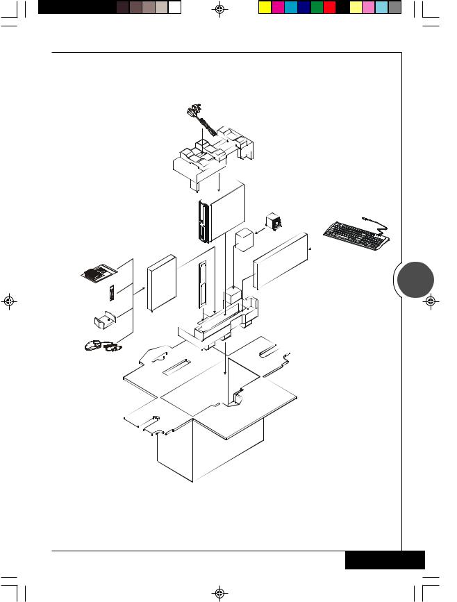
■ Items included in the package
Power Cord
*CPU cooler |
(Option) |
PC |
Softward and |
*Keyboard |
|
Manuals |
||
(Option) |
||
|
||
|
3 |
|
Cabels |
|
|
|
Front |
|
Foot Stand |
Decorative Panel |
|
|
||
*Mouse |
|
|
(Option) |
|
Specification with “Option” are subject to change without notice.
 English
G-MAXTM FB Series User's Manual
I.Chassis
Dimensions 428(D)mm x 92(W)mm x 326(H)mm
The casing of this computer adopts UL certified materials and bases with the convenient design of saving space and screws for installing one 5.25" and three 3.5" storage devices. It is very easy to remove the upper casing by loosening one screw and removing the lower panel and upper casing with one movement for the purpose of attaining an easy and convenient maintenance. The design of the computer casing allows for the function of electromagnetic interference (EMI) control, and meets the requirements of the computer safety specifications.
II.Motherboard
Please refer to the Motherboard User's Guide for the specifications and related introduction of the motherboard equipment in this system.
III. Power Supply
This computer adopts a T.F.X. power supply, and supports the functions of turning off the system by software. The factory default voltage is 230V.
Note: Please confirm the default voltage of the country before turning on the computer.
4 |
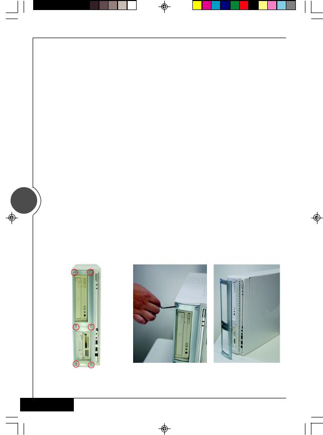
IV. Changing Front Decorative Panels |
|
|
|
|
|
|
|
1. Loosen the 6 screws on the front decorative |
2. |
Remove the front panel, and replace it |
|
panel. |
|
with another bundled front panel. |
|
Please use the hexagonal wrench bundled in |
3. |
Secure the screws back into the position |
|
the system to loosen or tighten the screws. |
|
to complete the procedure of changing |
|
Clockwise: for tightening the screw |
|
front decorative panels. |
|
Counterclockwise: for loosening the screw |
|
|
English 

G-MAXTM FB Series User's Manual
V. Installing the System
1. Unscrew the rear casing, and push the upper casing toward the front panel.
2.After loosening the 3 front screws and pulling out the optical disk drive, loosen the screws of the hard disk drive rack and then remove the hard disk drive rack.
Pull and lift the optical disk drive rack.
5
 Loosen the screws, and remove the hard disk drive rack.
3. Put the hard disk drive into the rack, and align the screws at the screw holes.
4. CPU
4-1. Place the CPU into the CPU socket on the motherboard. Make sure that you have lifted the transversal lever and aligned the aslant side of the CPU along the aslant side of the CPU socket.
4-2. After CPU is secured tightly onto the CPU socket, release the transversal lever and attach it to the CPU socket.
4-3. Evenly spread the heat dispersion paste on the CPU and make sure it totally covers the CPU. The CPU fan must be tightly attached on the CPU to maximize the effect of heat dispersion.
4-4. Connect the CPU fan connector to the CPU FAN position on the motherboard.
 English
G-MAXTM FB Series User's Manual
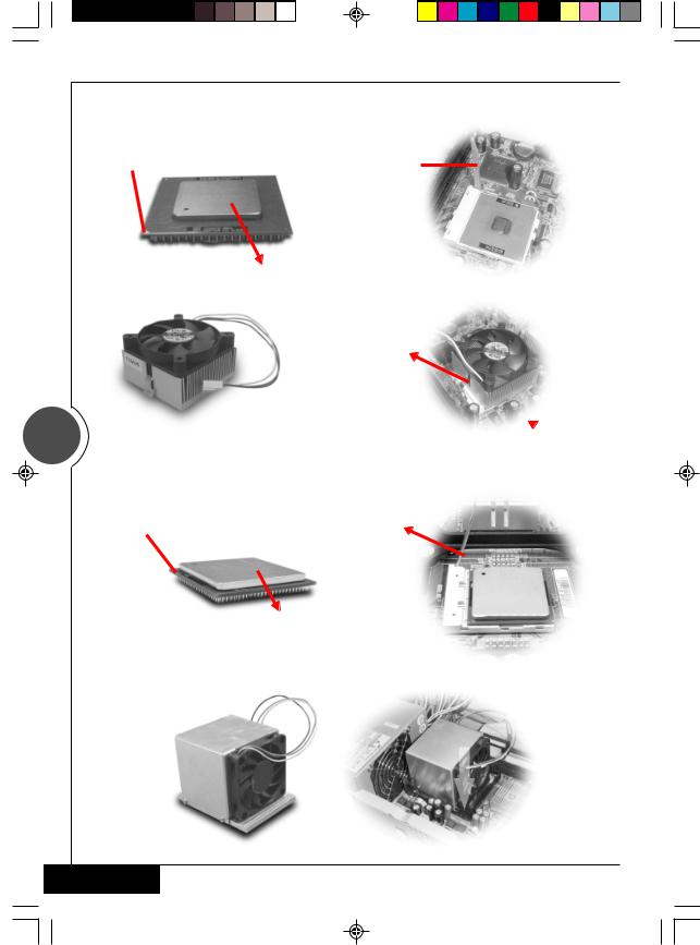
A. For Intel® Pentium® III and Intel® Celeron® processors
CPU Pin |
Pull the transversal lever |
|
|
Evenly spread the heat |
|||
|
dispersion paste on the CPU |
|||
|
Latch the hooks on |
|||
|
both sides of the CPU |
|||
|
securely into the CPU |
|
|
|
|
|
|||
6 |
socket |
|
|
|
|
|
|
||
Pix the cooler on the rack. |
||||
|
||||
B. For Intel® Pentium® 4 processors |
||||
CPU Pin |
Pull the transversal lever |
|||
Evenly spread the heat dispersion paste on the CPU
Fix the cooler on the rack.
English 
 Loading...