


GS15 plus
USER'S MANUAL
COPYRIGHT NOTICE
COPYRIGHT 1995 Gerber Scientific Products, Inc. All Rights Reserved.
This document may not be reproduced by any means, in whole or in part, without written permission of the copyright owner.
This document is furnished to support the GS15 plus. In consideration of the furnishing of the information contained in this document, the party to whom it is given assumes its custody and control and agrees to the following:
1.The information herein contained is given in confidence, and any part thereof shall not be copied or reproduced without written consent of Gerber Scientific Products, Inc.
2.This document or the contents herein under no circumstances shall be used in the manufacture or reproduction of the article shown and the delivery of this document shall not constitute any right or license to do so.
PRINTED IN USA
plus
GS15 , Knife Mode Switching, Corner Correcting Technology, IP Plus, Gerber Mask, and GERBER EDGE are trademarks of Gerber Scientific Products, Inc. GRAPHIX ADVANTAGE is a registered trademark of Gerber Scientific Products, Inc. 3-in-1 is a registered trademark of Boyle-Midway, Inc. HP-GL is a registered trademark of Hewlett Packard. 3M, ScotchCal, and Scotchlite are trademarks of 3M.
FCC NOTICE
This equipment has been tested and found to comply with the limits for a Class A digital device, pursuant to Part 15 of the FCC rules. These limits are designed to provide reasonable protection against harmful interference when the equipment is operated in a commercial environment. This equipment generates, uses, and can radiate radio frequency energy and, if not installed and used in accordance with the instruction manual, may cause harmful interference to radio communications. Operation of this equipment in a residential area is likely to cause harmful interference in which case the user will be required to correct the interference at his own risk.
This digital apparatus does not exceed the Class B limits for radio noise emissions from digital apparatus set out in the Radio Interference Regulations of the Canadian Department of Communications.
Le present appareil numerique n'emet pas de bruits radioelectriques depassant les limites applicables aux appareils numeriques de la classe B prescrites dans les Reglements sur le brouillage radioelectrique edicte par le Ministere des Communications du Canada.

TABLE OF CONTENTS |
|
INTRODUCTION .............................................................................................................. |
1 |
Description ............................................................................................... |
1 |
Performance.............................................................................................. |
1 |
Convenience ............................................................................................. |
2 |
Support Information ................................................................................. |
2 |
PACKAGE CONTENTS ................................................................................................... |
5 |
INSTALLATION ............................................................................................................... |
7 |
Plotter Work Area .................................................................................... |
7 |
Connect to the Plotter ............................................................................... |
8 |
Communication Parameters...................................................................... |
8 |
Power Cords ............................................................................................. |
9 |
Power-Up Sequence ............................................................................... |
10 |
SETUP.............................................................................................................................. |
11 |
Plotter Selection ..................................................................................... |
11 |
Add Plotters............................................................................................ |
12 |
Delete Plotters ........................................................................................ |
12 |
Assign Default Plotter ............................................................................ |
13 |
MATERIALS AND TOOLS............................................................................................ |
15 |
Materials................................................................................................. |
15 |
Helpful Hints.................................................................................... |
18 |
Tool Force Dial ...................................................................................... |
19 |
Settings............................................................................................. |
19 |
Adjustments ..................................................................................... |
20 |
TOOLS AND TOOL HANDLING .................................................................................. |
21 |
Storage.................................................................................................... |
21 |
Tool Holders........................................................................................... |
21 |
Pen Holder and Pens............................................................................... |
22 |
Pen Replacement.............................................................................. |
23 |
Pounce Wheel Holder............................................................................. |
25 |
Aligned Holes .................................................................................. |
25 |
Off-Center Holes.............................................................................. |
25 |
Plotter Speed .................................................................................... |
25 |
Pounce Wheel Holder Installation ................................................... |
25 |

Pounce Wheel Replacement ............................................................ |
26 |
Knife Holder and Blades ........................................................................ |
27 |
Blade Wear ...................................................................................... |
27 |
Blade Damage .................................................................................. |
27 |
Knife Holder Installation ................................................................. |
28 |
Blade Replacement .......................................................................... |
30 |
OPERATION.................................................................................................................... |
33 |
Power-Up................................................................................................ |
33 |
Front Panel ............................................................................................. |
34 |
SLEW Keys ..................................................................................... |
35 |
SLOW Key....................................................................................... |
35 |
SWIVEL KNIFE.............................................................................. |
36 |
INIT KNIFE ..................................................................................... |
36 |
RUN SINGLE .................................................................................. |
37 |
RUN CONT ..................................................................................... |
38 |
RESET ............................................................................................. |
40 |
SPECIAL DIAGNOSTICS............................................................................................... |
41 |
Diagnostic Options ................................................................................. |
42 |
Wagon Wheel Test Plot ................................................................... |
43 |
Square/Circle Test Plot .................................................................... |
44 |
X08 Cut Test.................................................................................... |
45 |
ERROR CONDITIONS.................................................................................................... |
47 |
Error Codes ...................................................................................... |
48 |
SERVICE AND MAINTENANCE.................................................................................. |
49 |
Cleaning and Lubrication ....................................................................... |
49 |
Tool Holders and Carriage Spindle Bore......................................... |
49 |
Carriage and Ball Bushing............................................................... |
50 |
Sprockets and Bail Arms ................................................................. |
52 |
Fuse Replacement................................................................................... |
53 |
PLOTTER ADJUSTMENTS ........................................................................................... |
55 |
Troubleshooting Guide........................................................................... |
56 |
Z Axis (Tool Height) Adjustment .......................................................... |
57 |
Symptoms......................................................................................... |
57 |
Objective .......................................................................................... |
57 |
Adjustment Procedure...................................................................... |
57 |
Theta Axis (Tool Rotation) Adjustment ................................................ |
61 |
Symptoms......................................................................................... |
61 |

Objective .......................................................................................... |
61 |
Adjustment Procedure...................................................................... |
61 |
X Axis Belt Adjustment ......................................................................... |
66 |
Symptoms......................................................................................... |
66 |
Objective .......................................................................................... |
66 |
Adjustment Procedure...................................................................... |
66 |
Y Axis Backlash Adjustment ................................................................. |
69 |
Symptoms......................................................................................... |
69 |
Objective .......................................................................................... |
69 |
Adjustment Procedure...................................................................... |
69 |
Drum End Play Adjustment.................................................................... |
73 |
Symptoms......................................................................................... |
73 |
Objective .......................................................................................... |
73 |
Adjustment Procedure...................................................................... |
73 |
1
INTRODUCTION
Description
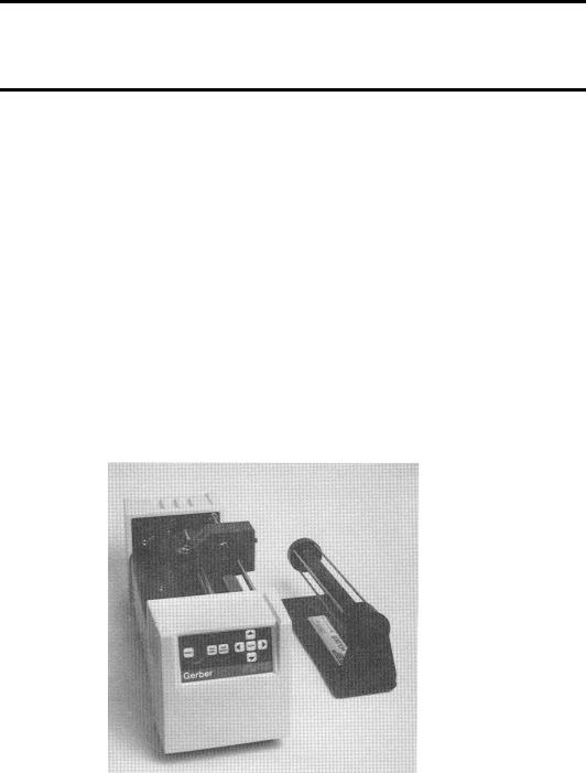
The GS15 plus is a state of the art 15-inch (38.1 cm) plotter designed for use with the GRAPHIX ADVANTAGE system and other sign design systems.
Note: When used with GRAPHIX ADVANTAGE systems, the GS15 plus requires GRAPHIX ADVANTAGE 4.3 or higher. When GS15 plus is used
with other sign design systems, contact the system manufacturer to obtain a driver for the GS15 plus.
The GS15 plus features Gerber's exclusive Knife Mode Switching™ Technology, which offers the operator a choice of two cutting modes selectable from the plotter keypad:
!Tangential Knife Mode keeps the blade aligned with the direction of plotting motion for cutting thick materials such as sandblast stencil and for pouncing patterns.
!Swivel Knife Mode is used for rapid cutting of all but the most demanding materials such as sandblast stencil. Gerber's exclusive Corner Correcting Technology™ assures sharp, easy-to-weed corners in swivel knife mode.
Performance
The GS15 plus is designed to precisely register graphics up to 50 yards (45.7 meters) long using carbide blades for crisp, sharp cuts.
When used with the GRAPHIX ADVANTAGE, the GS15 plus uses the Plot Spooler feature to receive and plot files while the operator continues to design at the system.

2 GS15 plus
Convenience
GS15 plus has many features that make it easy and convenient to use:
!Accepts any standard Gerber materials in 15-inch (38.1 cm) wide rolls.
!Draws, cuts and pounces up to 12.75 inches (32.4 cm) high. Using the GRAPHIX ADVANTAGE system Panel feature, the GS15 plus can cut text or graphics in strips up to 96 feet (29.3 meters) long and 12.75 inches (32.4 cm) wide.
!Adjustable tool force for uniform cutting with the turn of a dial.
!Stepper motor drive for consistent performance and easy maintenance.
!On-board 4K buffer in addition to GRAPHIX ADVANTAGE buffers.
!Quick installation.
!Simple to use keypad requires minimum training.
Support Information
Gerber pioneered plotter technology with quality engineering designs that consider operator convenience. Performance of the GS15 plus plotter is assured by:
!24 hours of finished product testing before shipment, in addition to testing during the manufacturing process.
!Customer support through Gerber Field Service Department.
!Step-by-step user's manual.
"If you require assistance installing or operating the GS15 plus plotter, contact your distributor or GSP Field Service Department at 800-828-5406 (in the USA), or fax at 203-645-2448.

Introduction 3
About This Manual
This manual explains the installation and operation of the GS15 plus
plotter. It tells you how to assemble, install, operate, and maintain your GS15 plus as follows:
!The "Introduction" provides information about the GS15 plus and a list of contents of the shipping crates.
!"Installation" contains instructions for plotter assembly, installation, and connection to the GRAPHIX ADVANTAGE.
!"Setup" contains instructions for adding the plotter to the GRAPHIX ADVANTAGE.
!"Materials and Tools" gives information about materials, loading the vinyl, and using the tool force dial.
!"Tools and Tool Handling" discusses procedures on using and replacing the pens, knives, and pounce wheel.
!"Operation" provides information about plotter operation and slew key functions.
!"Special Diagnostics" presents examples and instructions for diagnostic tests.
!"Error Conditions" lists common error conditions and corrective procedures.
!"Service and Maintenance" provides cleaning, lubricating, and fuse replacement instructions.
!"Plotter Adjustments" includes a troubleshooting guide as well as symptoms of plotter adjustment problems.

4 GS15 plus
Conventions
The following conventions are used in this manual:
Note: A note contains important information which could affect successful completion of a task.
CAUTION: A caution statement contains information which, if not observed, could result in damage to the equipment.
WARNING: A warning statement contains information which, if not observed, could result in personal injury.

5
PACKAGE CONTENTS
This section lists the contents of the GS15 plus shipping container. As you unpack the GS15 plus plotter, inspect all items for damage that may
have occurred during shipping. Report any damage to your dealer at once. Save all packaging materials in case it becomes necessary to transport the plotter at a future date.
The GS15 plus package contains the following:
!GS15 plus plotter assembly
!Roll holder
!Small components consisting of: 1 10-yard roll vinyl (US only)
1 Plotter power cord
110-foot RS-232 cable
2fuses
1 Vinyl letter squeegee
1 User's manual
1 Warranty card
1 Service contract
1 Swivel knife holder with blade
1 Spare swivel knife blade
1 Tool kit
1 Paper sample (International only)

6 GS15 plus
Contents: Tool Kit
1 Pen holder with pen
1 Tangential knife holder with blade
1 Pounce wheel holder
3 Tool lift washers (on tool holders)
1 Allen wrench
1 Pair tweezers
1 Spare red pen
1 Spare blue pen
1 Envelope containing 2 spare lift washers
3 Spare cone-shaped tool caps
1 Capsule containing:
2 Spare knife blades
1 Spare pounce wheel
1 Pen height gage
7
INSTALLATION
Please unpack the plotter boxes and inventory the contents before you begin to assemble the plotter. Follow these instructions to install the GS15 plus plotter to any GRAPHIX ADVANTAGE. Installation of the GS15 plus to other sign design systems is described separately.
Note: Should you experience difficulty during installation of the
GS15 plus to the GRAPHIX ADVANTAGE system, contact Gerber Field Service Department at 800-828-5406.
Plotter Work Area
1.Carefully remove the GS15 plus from its packaging materials and place it near the GRAPHIX ADVANTAGE system. The cable is 10 feet long, so the plotter need not be located immediately beside the console; however, it should be close enough so there will be no strain on the cable after installation.
2.Place the material roll holder next to the plotter on the right side.

8 GS15 plus
Connect to the Plotter
CAUTION: Be sure power is turned off and the power cord is unplugged at both the GRAPHIX ADVANTAGE and the plotter.
1.Insert the 9-pin connector at the end of the RS-232 cable into the 9- pin RS-232 connector on the back of the GRAPHIX ADVANTAGE. This connector is normally labeled Plotter or COM Port 2.
2.Carefully align all pins. Use the connector thumb screws to secure the cable to the system.
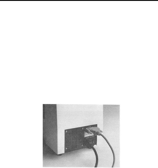
3.Insert the 25-pin connector at the end of the RS-232 cable into the 25-pin RS-232 connector on the back of the plotter.
4.Carefully align all pins. Secure the cable to the plotter with the connector thumb screws.
Note: If a plotter is already installed in the PLOTTER port on the GRAPHIX ADVANTAGE, use the TABLET port to install a second plotter.
Communication Parameters
If you are connecting the GS750 plus to a system other than the GRAPHIX ADVANTAGE, the plotter uses these RS-232 communication parameters:
Communication Parameters
9600 Baud
No Parity
8 Data Bits
1 Stop Bit
Xon/Xoff Flow Control
Installation 9
The plotter has a 25DB female connector with these pin assignments:
Pin |
Signal |
|
|
2 |
Tx |
|
|
3 |
Rx |
|
|
4 |
RTS |
|
|
5 |
CTS |
|
|
7 |
Sig Gnd |
|
|
All other pins are not connected.
Power Cords
1.Insert the female connector of the GS15 plus plotter power cord into the socket on the rear panel of the plotter.
2.Connect the power cords for both the GRAPHIX ADVANTAGE system and the GS15 plus to the multiple outlet strip included with the GRAPHIX ADVANTAGE. The strip should be plugged into a standard, grounded electrical outlet (115V +/- 10% AC, 60 Hz or 230V AC, 50 Hz).
3.Turn power on at the system and the plotter.

10 GS15 plus
CAUTION: When the power is on, never try to manually move
the carriage, move the drum, rotate the tool, or force the tool up or down. Attempting to manually move the GS15 plus in any axis
of movement while the power is on may damage the plotter.
Power-Up Sequence
When the GS15 plus is turned on, the following sequence occurs:
1.A short beep sounds, the Power light comes on, and the RUN CONT, RUN SING, and SWIVEL KNIFE lights blink.
2.As the GS15 plus performs self-check tests, the lights over the RUN and SWIVEL KNIFE keys flash, and one additional beep sounds.
3.When the self-check is complete, the lights blink and a beep sounds.
4.The plotter goes off-line in tangential knife mode. Only the Power light remains on. This is the initial setting at power-up.
Note: Rapid, continuous beeping and flashing lights may signal a selfcheck error. See the "Error Conditions" section for more information.
11
SETUP
After connecting the plotter to the GRAPHIX ADVANTAGE, you will
use the GSP Setup program in GRAPHIX ADVANTAGE to make the GS15 plus accessible.
Note: When the GS15 plus is used with sign design systems other than GRAPHIX ADVANTAGE, contact the system manufacturer to obtain a driver for the GS15 plus and for setup information.
Plotter Selection
1.Double-click on the GSP Setup icon to open GSP Setup.
2.Click on Setup. The Setup drop-down menu appears.
3.Click on Plotter. The Add or Delete Plotter(s) dialog box appears.
4.Click on GS15 plus in the Plotters list box to highlight it.
5.Click on the port to which the plotter is connected (COM1, COM2, COM3, or COM4) in the Ports box.
6.Click on Add. GS15 plus appears in the Ready for Plotting list box. Your system is now set up to use the GS15 plus plotter.

12 GS15 plus
Note: The Default Plotter note in the lower right corner of the dialog box tells you the name of the plotter your jobs will be sent to unless otherwise specified in the Plot program.
7.Click on Continue. The screen will return to the GSP Setup Menu.
8.Double-click on the Control Bar to exit the GSP Setup Menu. The
system will return to the GSP GRAPHIX ADVANTAGE program group and you can now access the GS15 plus plotter.
Add Plotters
Multiple plotters can be added to your system. They must be added one by one.
1.Click on the plotter you wish to add from the plotters list box.
2.Click on the port it will be connected to.
3.Click on Add. The highlighted plotter is added to the Ready for Plotting list box.
Note: For each plotter you add, a number is added after the plotter model number (for example, GS 15-1 for the first plotter added,
GS 15-2 for the second).
Delete Plotters
To remove plotters from the system:
1.In the Ready for Plotting box, click on the name of the plotter to be deleted.
2.Click on Delete.

Setup 13
Assign Default Plotter
A default plotter can be assigned if more than one plotter is connected to the GRAPHIX ADVANTAGE.
Note: There must be two or more plotter names in the Ready for Plotting box to select a default plotter. If only one plotter is installed to the GRAPHIX ADVANTAGE system, that plotter will automatically be assigned as the default plotter.
1.Highlight the name of the desired default plotter in the Plotters box.
2.Click on Preference.
3.Click on OK. The name of the default plotter selected will appear below the words Default Plotter.
4.Click on Continue. The screen returns to the GSP Setup menu.
5.Double-click on the Control Bar to exit the GSP Setup menu. The system will return to the GSP GRAPHIX ADVANTAGE program group.

15
MATERIALS AND TOOLS
Materials
The GS15 plus uses the same plotting materials as all Gerber plotters. Gerber vinyl products in high performance or intermediate grades are available in translucent, reflective, or metallic finishes and come in a wide range of colors. Also available are direct-cut screenprint stencil, ruby photo film, paint masking material, rubber sandblast stencil material and heat transfer materials. Consult your Gerber distributor for further information about available materials, colors and prices. Always insist on Gerber authorized materials for highest quality results.
To load material
CAUTION: it is recommended that you load material without a tool in the carriage to prevent damaging the knife blade.
1.Slide the roll of material to be used onto the roll holder. Pull the end of the material away from and over the top of the roll holder toward the plotter.
CAUTION: when power is on, the carriage spindle must be moved only by using the slew keys. attempts to manually move the plotter drum, rotate or force the tool up or down will damage the plotter.
CAUTION: While power is off, center the carriage by gently pushing toward the center of its travel. Take care to move the carriage slowly and firmly by gripping the right end of the carriage housing, not by gripping the carriage spindle.
CAUTION: Do not use the way shafts to lift or turn the GS15 plus. This will damage the system and reduce plotting accuracy.
16 GS15 plus
2.Center the carriage spindle preferably by using the slew keys (see "Front Panel" section) or manually, with certain precautions as outlined here. Be sure that the carriage spindle is not located at either extreme end of its travel and that both ends of the rubber drum can be reached easily.
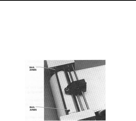
3.Open the bail arms at either end of the drum by pulling them up and away from the drum.
4.Using the slew (arrow) keys, rotate the drum until three closely spaced pins are visible. These three sprocket pins are used to align the material.

Materials and Tools 17
To feed and align material
1.Feed material under the black cam shaft and over the rubber drum. See the illustration below.
2.Place the holes in the material over the sliding sprocket pins first. Match the three closely spaced sprocket pins and holes.
3.Slide the material and the sliding sprocket to reach the fixed sprocket and place the material over these sprocket pins.
4.Center the bail arms over the sprockets. Move the adjustable bail arm at the rear of the plotter slightly forward or backward to accommodate small differences in the material width. Securely close the front bail arm first and then the rear bail arm.

18 GS15 plus
HELPFUL HINTS
!When you change materials, open the bail arms and roll the material back onto the roll. Tape the ends securely to prevent the roll from unraveling.
!Before unrolling vinyl for a job, determine how much material you need. Check the length of the longest line in the job, or the width of an automatically laid out sign or digitized design. Remember that if you are plotting in the Axis Swap mode, you need to consider the height of the job rather than its width.
!The most practical way to unroll material for a job is to use the slew keys on the plotter. It is best to unroll more than enough material, rather than "just enough," in case your estimate is not accurate. You may also pull material from the roll by hand. This may be the simplest method if you are plotting relatively small jobs.
!When you have advanced enough material for the job, feed it back through the plotter, or otherwise position it appropriately according to the tool start position selected from GRAPHIX ADVANTAGE. If you have a large quantity of material piling up on the table, be sure to arrange the material in loose accordion folds so it can feed easily. Make sure the material is positioned to feed straight into the plotter rather than at an angle.
Materials and Tools 19
Tool Force Dial
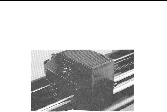
The tool force dial on the front of the housing indicates the tool force setting and the amount of tool force, or pressure, that is applied to the tool during operation. This pressure ensures uniform cuts and pen lines. Tool force can be adjusted by turning the small knob on the end of the tool force housing, as shown in the illustration below.
SETTINGS
The Plotter User Reference Card at the end of this manual lists approximate tool force settings. Be sure to refer to this list of settings when changing materials or applications. Below are some initial suggestions:
!For drawing, start with a tool force setting of about .5. If your pen does not make a clear dark line, you may wish to increase the tool force setting.
!For pouncing, start with a setting between 5 and 6.
!When cutting regular vinyl in tangential knife mode, try a tool force setting of 1.
!When cutting regular vinyl in swivel knife mode, set the tool force setting at 1. The swivel knife will not pivot at corners and will begin to cut through the material if the pressure is set too high.
!Heavier material, such as reflective vinyl, requires increased tool force settings.
 Loading...