


Copyright Notice
COPYRIGHT 2006 Gerber Scientific International. All Rights Reserved.
This document may not be reproduced by any means, in whole or in part, without written permission of the copyright owner.
This document is furnished to support the ART Path and Auto-Carve User’s Guide. In consideration of the furnishing of the information contained in this document, the party to whom it is given assumes its custody and control and agrees to the following:
1.The information herein contained is given in confidence, and any part thereof shall not be copied or reproduced without written consent of Gerber Scientific International.
2.This document or the contents herein under no circumstances shall be used in the manufacture or reproduction of the article shown and the delivery of this document shall not constitute any right or license to do so.
Information in this document is subject to change without notice.
Printed in USA
GSP is a registered trademark, and ART Path, Auto-Carve, Sabre, Dimension, and OMEGA are trademarks of Gerber Scientific Products, Inc. HPGL is a trademark of Hewlett-Packard Company. Rowmark is a registered trademark of Rowmark, Inc. Microsoft and Windows are registered trademarks of Microsoft Corporation in the US and other countries.
FCC NOTICE
WARNING This is a Class A product. In a domestic environment this product may cause radio interference in which case the user may be required to take adequate measures.
This equipment has been tested and found to comply with the limits for a Class A digital device, pursuant to Part 15 of the FCC rules. These limits are designed to provide reasonable protection against harmful interference when the equipment is operated in a commercial environment. This equipment generates, uses, and can radiate radio frequency energy and, if not installed and used in accordance with the instruction manual, may cause harmful interference to radio communications. Operation of this equipment in a residential area is likely to cause harmful interference in which case the user will be required to correct the interference at his own risk.
This digital apparatus does not exceed the Class B limits for radio noise emissions from digital apparatus set out in the Radio Interference Regulations of the Canadian Department of Communications.
Le present appareil numerique n'emet pas de bruits radioelectriques depassant les limites applicables aux appareils numeriques de la classe B prescrites dans les Reglements sur le brouillage radioelectrique edicte par le Ministere des Communications du Canada.
Book One: Introduction to ART Path .................................................................................. |
1 |
Chapter 1: Setting up ART Path ........................................................................................... |
3 |
Unpacking/Installation.................................................................................................................... |
3 |
System requirements ........................................................................................................................ |
3 |
Installing the ART Path software option......................................................................................... |
4 |
Accessing ART Path.......................................................................................................................... |
4 |
Customer Support............................................................................................................................. |
5 |
Chapter 2: Reviewing the ART Path Toolbox..................................................................... |
7 |
Cancel Select...................................................................................................................................... |
7 |
Pointer................................................................................................................................................ |
7 |
Zoom.................................................................................................................................................. |
8 |
Unzoom ............................................................................................................................................. |
8 |
Male ................................................................................................................................................... |
9 |
Male Auto Inlay Parameters........................................................................................................ |
10 |
Female.............................................................................................................................................. |
12 |
Female Auto-Inlay Parameters.................................................................................................... |
13 |
Engrave............................................................................................................................................ |
15 |
Engraving Channel Cut Parameters ........................................................................................... |
15 |
Cleanout........................................................................................................................................... |
16 |
Direction ....................................................................................................................................... |
18 |
Auto-Inlay Parameters................................................................................................................. |
19 |
Use Diagonals............................................................................................................................... |
19 |
Drill.................................................................................................................................................. |
20 |
Nesting............................................................................................................................................. |
21 |
Horizontal Cutline .......................................................................................................................... |
22 |
Move Cutline................................................................................................................................... |
22 |
Auto-Carve 3D ................................................................................................................................ |
23 |
Prismatic .......................................................................................................................................... |
23 |
Set Start Point .................................................................................................................................. |
23 |
Book Two: Menus and Procedures ................................................................................... |
25 |
Chapter 3: File Menu ........................................................................................................... |
27 |
New.................................................................................................................................................. |
27 |
Open................................................................................................................................................. |
27 |
Close................................................................................................................................................. |
27 |
Save.................................................................................................................................................. |
28 |
Save As ............................................................................................................................................ |
28 |
Save Plot File ................................................................................................................................... |
29 |
Save to Spool File ............................................................................................................................ |
29 |
Save Parameters .............................................................................................................................. |
30 |
Place................................................................................................................................................. |
30 |
Library ............................................................................................................................................. |
31 |
Print ................................................................................................................................................. |
31 |
Print Setup....................................................................................................................................... |
31 |
Recently Used File list..................................................................................................................... |
31 |
Exit ................................................................................................................................................... |
31 |
Chapter 4: Edit Menu........................................................................................................... |
33 |
Undo ................................................................................................................................................ |
33 |
Cut.................................................................................................................................................... |
33 |
Copy and Paste................................................................................................................................ |
33 |
Paste from Composer................................................................................................................... |
34 |
Paste Back ..................................................................................................................................... |
35 |
Delete............................................................................................................................................... |
35 |
Select All.......................................................................................................................................... |
35 |
Reverse Select.................................................................................................................................. |
35 |
Select Open Shapes ......................................................................................................................... |
35 |
Select Unused Shapes ..................................................................................................................... |
36 |
Chapter 5: Shape Menu ...................................................................................................... |
37 |
Repeats............................................................................................................................................. |
37 |
Repeats dialog box ....................................................................................................................... |
37 |
Sizing Shapes................................................................................................................................... |
38 |
Percent Size dialog box................................................................................................................ |
39 |
Absolute Size dialog box ............................................................................................................. |
40 |
Join ................................................................................................................................................... |
41 |
Group............................................................................................................................................... |
42 |
Ungroup .......................................................................................................................................... |
42 |
Layer ................................................................................................................................................ |
42 |
SmartEdit Layer ........................................................................................................................... |
43 |
Chapter 6: Setup Menu ....................................................................................................... |
45 |
Tool Edit .......................................................................................................................................... |
45 |
Tool Information Dialog Box....................................................................................................... |
45 |
Tool Edit Dialog Box.................................................................................................................... |
46 |
Start/End Position .......................................................................................................................... |
48 |
Router Selection .............................................................................................................................. |
50 |
Use Material .................................................................................................................................... |
50 |
Material Size.................................................................................................................................... |
51 |
Nesting Setup.................................................................................................................................. |
52 |
Join Tolerance.................................................................................................................................. |
52 |
Show Tool Changer Position.......................................................................................................... |
53 |
Chapter 7: Tool Path Menu ................................................................................................ |
55 |
Tools Used....................................................................................................................................... |
55 |
Organize Tool Order dialog box ................................................................................................. |
55 |
Engrave............................................................................................................................................ |
56 |
Male ................................................................................................................................................. |
56 |
Female.............................................................................................................................................. |
56 |
Cleanout........................................................................................................................................... |
57 |
Drill.................................................................................................................................................. |
57 |
Toolpath Dialog Boxes.................................................................................................................... |
58 |
Understanding the Tool path ...................................................................................................... |
58 |
Setting Tool path parameters....................................................................................................... |
58 |
Applying additional features ......................................................................................................... |
61 |
Using tool path templates............................................................................................................ |
61 |
Applying a finish cut ................................................................................................................... |
63 |
Creating an inlay.......................................................................................................................... |
63 |
Applying climb milling................................................................................................................ |
64 |
Selecting Lead In/Lead Out ........................................................................................................ |
65 |
Setting the spindle speed ........................................................................................................... |
65 |
Using the Engrave command......................................................................................................... |
65 |
Additional information found in the Default Engrave Info Dialog Box................................... |
67 |
Using the Male tool path................................................................................................................. |
67 |
Applying a male basic cut ........................................................................................................... |
67 |
Applying a male finish cut .......................................................................................................... |
68 |
Applying an inlay ........................................................................................................................ |
69 |
Cutting stencils with the Female tool............................................................................................. |
70 |
Applying a Female basic cut ....................................................................................................... |
70 |
Adding a Female finish cut ......................................................................................................... |
72 |
Adding an inlay............................................................................................................................ |
73 |
Using Cleanout ................................................................................................................................ |
73 |
Selecting Direction ....................................................................................................................... |
73 |
Applying Use Diagonals.............................................................................................................. |
74 |
Selecting Cleanout shapes ........................................................................................................... |
75 |
Using Drill ....................................................................................................................................... |
77 |
Retrieving Drill symbols.............................................................................................................. |
77 |
Generating a Drill tool path......................................................................................................... |
78 |
Chapter 8: Output Menu..................................................................................................... |
81 |
Job Output Dialog Box.................................................................................................................... |
81 |
Position ......................................................................................................................................... |
82 |
Material Used ............................................................................................................................... |
82 |
Preposition.................................................................................................................................... |
82 |
Router Name ................................................................................................................................ |
83 |
Job Header Message..................................................................................................................... |
83 |
In-Place Repeats ........................................................................................................................... |
84 |
Repeats.......................................................................................................................................... |
85 |
Plotting Parameters...................................................................................................................... |
87 |
Tool Parameters............................................................................................................................ |
87 |
Chapter 9: Panel Menu ....................................................................................................... |
91 |
Horizontal Cutline .......................................................................................................................... |
91 |
Move Cutline................................................................................................................................... |
91 |
Panel Setup...................................................................................................................................... |
92 |
Chapter 10: View Menu....................................................................................................... |
95 |
Redraw............................................................................................................................................. |
95 |
Toolbars and Status Bar.................................................................................................................. |
95 |
Animate ........................................................................................................................................... |
95 |
Show Dry Haul Moves ................................................................................................................... |
96 |
Show Path Start Point ..................................................................................................................... |
96 |
Color Assignments.......................................................................................................................... |
96 |
Chapter 11: Window Menu ................................................................................................ |
99 |
New Window.................................................................................................................................. |
99 |
Cascade............................................................................................................................................ |
99 |
Tile ................................................................................................................................................... |
99 |
Arrange Icons .................................................................................................................................. |
99 |
Close All .......................................................................................................................................... |
99 |
File List ............................................................................................................................................ |
99 |
Chapter 12: Getting Help in ART Path ............................................................................ |
|
101 |
Finding a topic................................................................................................................................ |
|
101 |
Finding additional topics in the Topic pane.............................................................................. |
102 |
|
Finding previously-viewed topics ............................................................................................. |
|
102 |
Finding frequently-viewed topics.............................................................................................. |
|
103 |
Printing topics ................................................................................................................................ |
|
103 |
Copying topics ............................................................................................................................... |
|
104 |
Personalizing Help topics.............................................................................................................. |
|
104 |
Displaying the ART Path version.................................................................................................. |
|
104 |
Book Three: Introduction to Auto-Carve........................................................................ |
|
105 |
Chapter 13: Installing Auto-Carve ................................................................................... |
|
107 |
System Requirements .................................................................................................................... |
|
107 |
Installing ARC Station Firmware.................................................................................................. |
|
108 |
Installing the FACS-13 Control Board........................................................................................... |
|
109 |
Installing the Auto-Carve Option ................................................................................................. |
|
111 |
Chapter 14: Three-Dimensional Carving Tools.............................................................. |
113 |
|
Carving Tool Sharpness................................................................................................................. |
|
114 |
Selecting a 3-D Tool Path Auto-Carve ..................................................................................... |
|
115 |
Using the Default Carve Info dialog box |
V-Bottom............................................................. |
115 |
Default Roughing Tool Information Dialog Box....................................................................... |
118 |
|
Generating a 3D V bottom tool path.......................................................................................... |
|
120 |
Using the Default Carve Info Dialog Box |
Flat-bottom............................................................ |
121 |
Default Flat-bottom Tool Information Dialog Box.................................................................... |
124 |
|
Generating a Flat-bottom 3D tool path......................................................................................... |
|
125 |
Setting V-Tool parameters.......................................................................................................... |
|
125 |
Choosing basic carving parameters ........................................................................................... |
|
125 |
Using a roughing tool ................................................................................................................. |
|
126 |
Defining Depth Limitations........................................................................................................ |
|
128 |
Selecting Flat Bottom .................................................................................................................. |
|
129 |
Prismatic ......................................................................................................................................... |
|
133 |
Reviewing the Default Prismatic Info dialog box ..................................................................... |
133 |
|
Eliminating Rough Edges........................................................................................................... |
|
136 |
Generating a 3-D Tool Path ........................................................................................................... |
|
137 |
Smart Editing a Tool Path.............................................................................................................. |
|
137 |
Masking the Sign Blank ................................................................................................................. |
|
138 |
Routing the Design ........................................................................................................................ |
|
139 |
Initializing the Router (D200 or AR600) .................................................................................... |
|
139 |
To initialize a Sabre router to the table...................................................................................... |
|
140 |
To initialize a Sabre router to the material surface ...................................................................... |
141 |
|
Finishing the Design ...................................................................................................................... |
|
141 |
Appendix A: ART Path Glossary....................................................................................... |
|
143 |
Appendix B: Material Flatness......................................................................................... |
|
147 |
Manufactured Material.................................................................................................................. |
|
147 |
Wood............................................................................................................................................... |
|
147 |
Grain Type and Sawing Techniques.......................................................................................... |
|
147 |
Moisture Content and Humidity ............................................................................................... |
|
148 |
Shipping....................................................................................................................................... |
|
148 |
Storage ......................................................................................................................................... |
148 |
Carving into a Warped Panel........................................................................................................ |
148 |
Appendix C: Speeds and Feeds for Standard Router Motor....................................... |
149 |
Index .................................................................................................................................... |
151 |

1
Book One:
Introduction to ART Path
ART Path 32 is an OMEGA output tool that is used to link a Gerber routing system to OMEGA programs. The Gerber routing systems listed below can be used with the ART Path program:
♦Sabre series 404 and 408
♦Dimension 200
♦ADVANTAGE Router 600
ART Path allows you to benefit from the OMEGA Composer's design capabilities while offering routing features such as:
♦Climb Milling
♦Lead In/Lead Out
♦User-defined Tool Table
♦Nesting Placement
♦Drill
ART Path automatically generates tool paths for male, female, engraved, or cleanout tool paths. It also enables automatic cutting of inlay shapes with rounded edges, use of multiple cutters and/or depths of cut within the same job, and operator messaging while the job is being cut on the router.
Jobs created in Composer are brought into the ART Path program where the design may be viewed closely and nested for better positioning to conserve material.
3
Chapter 1:
Setting up ART Path
Unpacking/Installation
♦If you are adding the ART Path option to your existing OMEGA release, please continue with the instructions below (starting with the “Package contents” paragraph) in order to install ART Path on your system.
♦If you are upgrading to or have just purchased OMEGA, you should already have followed the instructions in the Getting Started guide for installing OMEGA as well as any other fonts, libraries, and options acquired, including ART Path. Refer to documentation for your particular router if necessary for instructions on physically connecting the router to the OMEGA system.
System requirements
Before ART Path can be installed and used, your system should be set up with the following releases:
♦OMEGA 2.0/2.1 with Microsoft® Windows® version 98, 2000, ME, or XP
♦OMEGA 2.5 and higher with Microsoft Windows version 2000 or XP
To verify your OMEGA release
1Right-click the GSP Tray icon that appears on the right end of the Windows status bar to open the Gerber Tray menu.
2Click About GSP Tray. The number in the Rbase field is your OMEGA version.
3Verify that the version listed in the Rbase field matches the software that you are installing.
4Click OK to return to your desktop.
4 |
Chapter 1 |
|
Setting up ART Path |
Installing the ART Path software option
This procedure describes loading ART Path as an option after OMEGA has been installed.
To install the ART Path software option
1Insert the OMEGA installation CD disk into the disk drive. The OMEGA Setup Wizard should automatically display. If it does not click Start > Run to display the Run dialog box. Type D:\Setup.exe and click OK (Where D:\ is the drive containing the disk).
2Click Install Products to display the Install Products menu.
3Click Install OMEGA 2.5. Follow the instructions until the Installation Type dialog box displays. Choose Add/Reload Individual components and click Next.
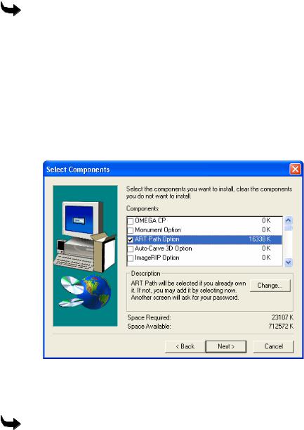
4At the Select Components dialog box turn on ART Path Option. If you have purchased the Auto-Carve Option turn on this option as well. Auto-Carve requires a password to load. Click Next to load the software.
5 When the installation completes, click Finish and restart your computer.
Accessing ART Path
To access Art Path
Click Start > Programs > GSP OMEGA > ART Path32.

5
Customer Support
!If you require assistance installing or using ART Path, contact your Gerber distributor or Gerber Technical Support at:
Phone: 860-644-6971
Fax: 860-871-3862
e-mail: gsptech@gspinc.com
Please use a phone that is close to your system and have the following available before calling:
♦Microsoft Windows version numbers
♦System serial number
♦Router serial number
♦Router User Manual
If you have an OMEGA system, please have the following information ready as well:
♦OMEGA, Windows, and hardware utility CD’s.
♦OMEGA Reference Guide
♦The names of any peripheral (output) devices, such as a printer.
7
Chapter 2:
Reviewing the ART Path Toolbox
The Toolbox is located on the left side of the ART Path window. The toolbox contains tools, which allow the user to select, zoom in, and position the shapes in a design. You can also choose a tool path from the Toolbox.
Cancel Select
Cancel Select makes all previously selected shapes unavailable. It is useful in correcting a selection mistake.
To deselect a shape, click on the Cancel Select Tool. The selected shape becomes deselected.
Pointer
Pointer selects and deselects a shape.
When the Pointer Tool is clicked on in the toolbox, the mouse pointer changes to a pointing finger. The selected shape is redrawn with a solid blue line.
The Pointer Tool is also used for Smart Editing. Smart Edit allows the user to change the tool path settings. The user returns to the specific tool path dialog box for editing the desired parameters. A shape or design does not have to be selected first before it may be Smart Edited.
A shape must be selected with the Pointer Tool first before choosing a tool path. When using the rubber band method of selection, the rubber band box must surround the entire shape.
To select or deselect a shape
1Click the Pointer Tool. The mouse pointer changes to a pointing finger when moved into the working area.
2Move the Pointer Tool until it touches the shape and click the left mouse button. The shape is selected and redrawn in solid blue lines. If a shape is deselected, it is redrawn in a contrasting color.
To select or deselect multiple shapes
1Click the Pointer Tool. The mouse pointer changes to the Pointer Tool when moved into the working area.
2Move the Pointer Tool to a top corner above the shapes to be selected.
3Click and drag the tool across the shapes to the opposite corner. As the Pointer Tool is moved, a rubber band box will be drawn around it.

8 |
Chapter 2 |
|
Reviewing the ART Path Toolbox |
4Release the mouse button. The shapes are selected and redrawn in solid blue lines. If shapes are deselected, they are redrawn in a contrasting color.
Zoom
Zoom magnifies a piece of a design for a closer look. When the Zoom Tool is clicked on, the mouse pointer changes to a cross hair with a small magnifying glass shown in the lower right corner. The design is centered and fills as much of the working area as possible after each zoom.
All tools and menu commands work on a zoomed design as on an unzoomed design. Line lengths remain the same at every magnification.
To magnify part of a design
1Click the Zoom Tool. The tool is highlighted. The mouse pointer changes when moved into the working area.
2Move the Zoom Tool to a top corner above the shape to be magnified.
3Click and drag the Zoom Tool across the shape to be magnified. A dotted box is drawn around the shape.
4Click the right mouse button. The area within the box is magnified.
5Repeat Steps 1-4 to magnify the shape again.
Unzoom
The Unzoom Tool returns a design to its original appearance or to the previous appearance in a series of zooms.
Unzoom remembers the appearance of the previous five zooms performed on the same design. Clicking the left mouse button on the Unzoom Tool backtracks the working area to the previous zoom appearance. Clicking the right mouse button on the Unzoom tool returns the design to its original appearance before the first zoom.
Unzoom is available only after using the Zoom Tool. Only the Unzoom Tool remembers the last five zooms. Backtracking to a sixth zoom automatically returns the design to its original appearance.
To return a design to the previous appearance in a series of zooms
1Click the Unzoom Tool.
2Click the left mouse button. The magnified design redraws to its last appearance.
3Repeat steps 1 and 2 to backtrack through each previous appearance in the series of zooms.
Note: The design automatically returns to its original appearance on the sixth backtrack.
9
To return a design to full size after magnifying it
Click the Unzoom Tool with the right mouse button.
Male
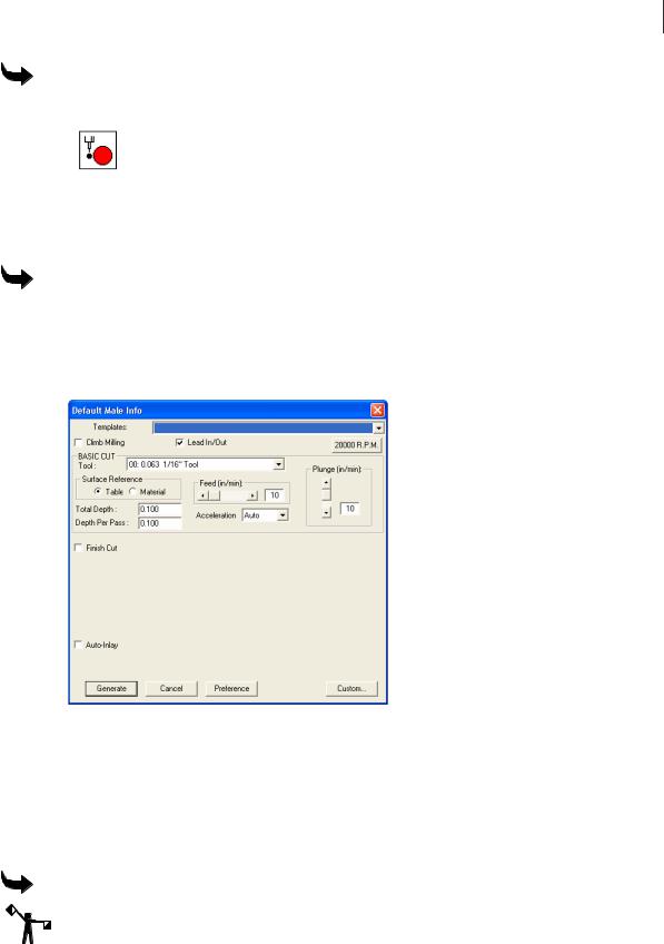
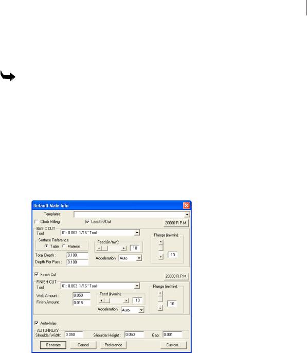
Male allows the user to generate a tool path to create a solid shape from the material. Clicking on the Male Tool opens the Default Male Info Dialog Box. Refer to the “Toolpath Dialog Boxes” section for more information. The shape must be selected before the Male Tool is available for use.
To set male basic cut parameters
1Select the shape to be routed with the Pointer Tool. The selected shape changes in color to show it is selected.
2Click the Male Tool in the Toolbox. The Default Male Info dialog box appears on screen.
3In Basic Cut, click the down arrow on the right side of the Tool entry box. A drop down list box appears.
4Click the desired routing tool.
5Enter the desired parameters for Total Depth, Depth Per Pass, Feed Rate, Plunge Rate, RPM’s, Acceleration, and Surface Reference into the dialog box.
6Click Generate, the tool path appears on screen in a contrasting color.
To set male and finish cut parameters
Note: It is important for Finish Cut to use the same tool used for Basic Cut.
1Select the shape to be routed with the Pointer Tool. The selected shape changes in color to show it is selected.
2Click Male from the Tool Paths menu. The Default Male Info Dialog Box opens.
10 Chapter 2
Reviewing the ART Path Toolbox
3Click the down arrow on the right side of the Tool entry box. A drop-down list box appears.
4Click the desired routing tool.
5Enter the desired Basic Cut parameters.
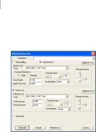
6Turn on Finish Cut to display the Finish Cut parameters.
7Click the down arrow on the right side of the Tool entry box. A drop down list box appears.
8Click the desired routing tool.
9Enter the desired Finish Cut parameters for Web Amount, Finish Amount, Feed Rate and Plunge Rate.
10Click the 20000 R.P.M. button. The Enter Spindle Speed dialog box appears. Type the desired speed (between 6,000 and 24,000 RPM) and click OK to close the dialog box.
11Click Generate in the tool path information dialog box. The Basic Cut tool path and the Finish Cut tool paths appear on screen in contrasting colors.
Male Auto Inlay Parameters
Auto-Inlay parameters provide information on how the two shapes (male and female) are routed. The two auto-inlay shapes must be routed with the same tool. Auto-Inlay is an optional parameter.
Auto-Inlay parameter values for shoulder width, shoulder height, and gap are entered when a Shoulder is cut from the material. A Shoulder prevents light from showing through gaps between the inlaid shapes. A Shoulder is also useful to hold letters in place. Click on the AutoInlay check box. An X appears in the check box and the Auto-Inlay parameters appear in the dialog box.
♦The Shoulder Width should be less than 2 or equal to the tool size. A typical shoulder width is .125 inches (3.175mm).
11
♦A typical Shoulder Height is .125 inches (3.175mm).
♦The Gap is the amount of material that is cut between the male and female shapes. The Gap enables the two shapes to fit together properly. A recommended gap is .005 inches (.127mm) wide.
To set male and auto-inlay parameters
1Select the shape to be routed with the Pointer tool. The selected shape changes in color to show it is selected.
2Click Tool Path from the menu bar.
3Click Male to display the Default Male Info Dialog Box.
4Click the down arrow on the right side of the Tool entry box. A drop-down list box appears.
5Click the desired routing tool.
6Enter the desired Basic Cut parameters.
7Turn on Auto-Inlay to display the Auto-Inlay parameters.
8Enter the desired parameters for Shoulder Width, Shoulder Height and Gap (see the guidelines above for reference.) If no shoulder is desired, set shoulder width & height to zero.
9Click Generate in the tool path information dialog box. The Basic Cut tool path, the Finish Cut tool path, and the Inlay Tool path appear on screen in contrasting colors.
12 Chapter 2
Reviewing the ART Path Toolbox
Female 
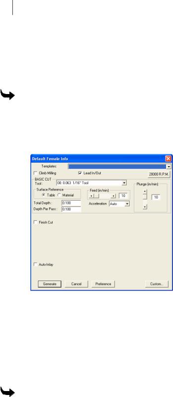
Female allows the user to generate a tool path to create a stencil from the material. Clicking on the Female Tool opens the Default Female Info Dialog Box. Refer to the “Toolpath Dialog Boxes” section for more information. The shape must be selected before the Female Tool is available for use.
To set female basic cut parameters
1Select the shape to be routed with the Pointer tool. The selected shape changes in color to show it is selected.
2Click Tool Path from the menu bar.
3Click Female to display the Default Female Info Dialog Box.
4Click the down arrow on the right side of the Tool entry box. A drop down list box appears.
5Click the desired routing tool.
6Enter the desired parameters for Total Depth, Depth Per Pass, Feed Rate, Surface Reference, RPM’s, Acceleration and Plunge Rate into the dialog box.
7Click the 20000 R.P.M. button. The Enter Spindle Speed dialog box appears. Type the desired speed (between 6,000 and 24,000 RPM) and click on OK to close the dialog box.
8Click Generate. The tool path appears in a contrasting color.
To set female and finish cut parameters
1Select the shape to be routed with the Pointer Tool. The selected shape changes in color to show it is selected.
2Click Tool Path from the menu bar.
3Click Female to display the Default Female Info Dialog Box.
13
4Click the down arrow on the right side of the Tool entry box. A drop-down list box appears.
5Click the desired routing tool.
6Enter the desired Basic Cut parameters.
7Click the Finish Cut check box, an X appears in the check box. The Finish Cut parameters appear on screen.
8Click the down arrow on the right side of the Tool entry box. A drop down list box appears. Choose the same tool that was used for the Female Basic Cut.
9Click the desired routing tool.
10Enter the desired Finish Cut parameters for Web Amount, Finish Amount, Feed Rate and Plunge Rate.
11Click the 20000 R.P.M. button. The Enter Spindle Speed dialog box appears. Type the desired speed (between 6,000 and 24,000 RPM) and click on OK to close the dialog box.
12Click Generate in the tool path information dialog box. The Basic Cut tool path and the Finish Cut tool paths appear on screen in contrasting colors.
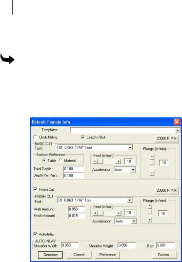
Female Auto-Inlay Parameters
The Auto-Inlay parameters are used when a Shoulder is cut from the material. The purpose of a Shoulder is to prevent light from showing through gaps between the inlaid shapes. A Shoulder is also useful to hold letters in place. Click on the Inlay check box. An X appears in the check box. The Auto-Inlay parameters appear in the dialog box.
♦The Shoulder Width should be less than the tool size. A typical shoulder width is .125 inches (3.175mm).
♦A typical shoulder height is .125 inches (3.175mm).
14 Chapter 2
Reviewing the ART Path Toolbox
♦The Gap is the amount of material that is cut between the male and female shapes. The Gap enables the two shapes to fit together properly. A recommended gap is .005 inches (.127mm) wide.
To set female auto-inlay parameters
1Select the shape to be routed with the Pointer Tool. The selected shape changes in color to show it is selected.
2Click Tool Path from the menu bar.
3Click Female to open the Default Female Info Dialog Box.
4Click the down arrow on the right side of the Tool entry box. A drop-down list box appears.
5Click the desired routing tool.
6Enter the desired Basic Cut parameters.
7Click the Auto-Inlay check box an X appears in the check box. The Auto-Inlay parameters can be entered.
8Enter the desired Auto-Inlay parameters for the Shoulder Width, Shoulder Height and Gap (see the guidelines above for reference.) If no shoulder is desired, set shoulder width & height to zero.
9Click Generate. Both the Auto-Inlay tool path and the Basic Cut tool path appear on screen in contrasting colors.
15
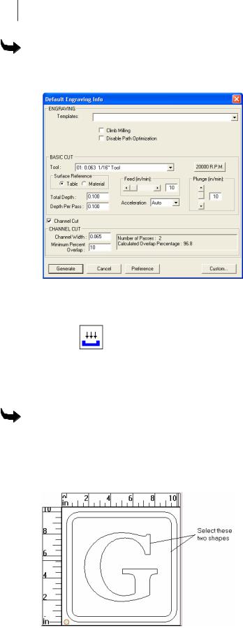
Engrave
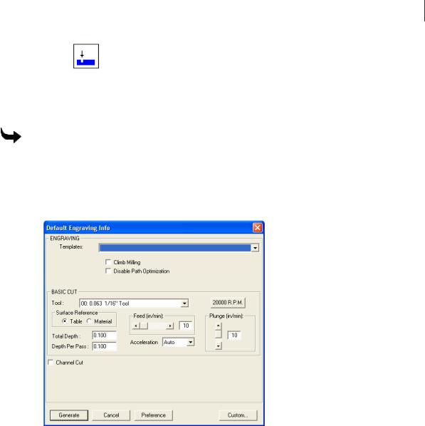
The Engrave Tool etches a design into the material on the shape's contour without using an offset. Clicking on the Engrave Tool opens the Default Engrave Info Dialog Box. Refer to the section “Toolpath Dialog Boxes” for more information. The shape must be selected before the Engrave Tool is available for use.
To set engraving parameters
1Select the shape to be routed with the Pointer Tool. The selected shape changes color to show it is selected.
2Click Tool Path from the menu bar.
3Click Engrave. The Default Engraving Info dialog box appears on screen.
4Click the down arrow on the right side of the Tool entry box. A drop-down list box appears.
5Click the desired Engraving Tool.
6Enter in the desired parameters for Total Depth, Depth Per Pass, Surface Reference, Acceleration, RPM’s and Plunge Rate into the dialog box.
7Click Generate to set the tool path. The tool path appears on screen in a contrasting color.
Engraving Channel Cut Parameters
The Channel Cut feature generates tool paths for channels whose width is larger than the diameter of the available cutters. Turn on Channel Cut and set the stroke width. ART Path automatically calculates the number of passes required and the percentage of overlap that occurs.
16 Chapter 2
Reviewing the ART Path Toolbox
To use Channel Cut
1In the Default Engraving Info box, turn on Channel Cut to display the Channel Cut dialog box.
2Enter a value for the Stroke Width of the crease channel.
3Click Generate to create a Channel Cut tool path for this job.
Cleanout
Cleanout routs an area of a shape without completely cutting through the material. Clicking on the Cleanout Tool opens the Default Cleanout Info Dialog Box. Refer to the section “Toolpath Dialog Boxes” for more information. The sha pe must be selected before the Cleanout Tool is available for use.
To set parameters to cleanout a background shape
To clean out a background around a shape, select the background and the shape it surrounds. If needed nest the shapes before generating the Cleanout tool path.
1Select the shapes to be routed with the Pointer Tool. The selected shape changes in color to show it is selected.

17
2Click Tool Path from the menu bar.
3Click Cleanout to open the Default Cleanout Info Dialog Box.
4Click the down arrow on the right side of the Tool entry box. A drop down list box appears.
5Click the desired routing tool.
6Enter the desired Cleanout parameters for the Total Depth, Depth Per Pass, Feed Rate, Plunge Rate, Surface Reference, Acceleration, RPM’s and Direction.
7Click Generate. The tool path appears in a contrasting color.
To set parameters to cleanout a foreground shape
1Select the foreground shape to be routed with the Pointer Tool. The selected shape changes in color to show it is selected.
2Click Tool Path from the menu bar.
3Click Cleanout. The Default Cleanout Info Dialog Box appears on screen.
4Click the down arrow on the right side of the Tool entry box. A drop-down list box appears.
5Click the desired routing tool.
18 Chapter 2
Reviewing the ART Path Toolbox
6Enter the desired Cleanout parameters for the Total Depth, Depth Per Pass, Feed Rate, Plunge Rate, Surface Reference, Acceleration, RPM’s and Direction.
7Click Generate. The tool path appears in a contrasting color.
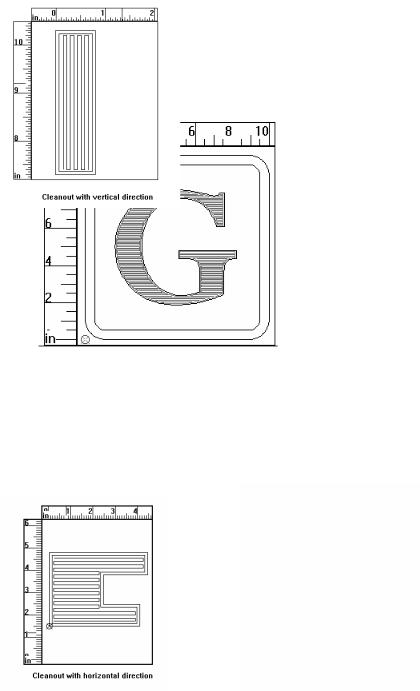
Direction
Cleanout Direction refers to the horizontal or vertical direction of the Cleanout tool path. Selecting a Direction in Cleanout makes cutting cleanout shapes more efficient.
Use Horizontal when the design contains many horizontal elements. Use Vertical when the design contains many vertical elements.
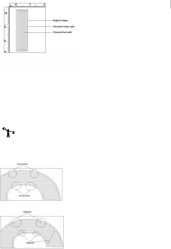
Cleanout tool path consists of two paths. The first is the cleanout path; the second path follows the shape contour and smoothes the edge.
19
Auto-Inlay Parameters
An inlay consists of a solid male shape that fits snugly into a stencil female shape or cleaned-out area. A cleanout shape can be cut as an inlay shape. By applying Auto-Inlay to a Cleanout tool path, the Cleanout shape is automatically cut with rounded corners. Auto-Inlay produces shapes with matching corner radii, which do not require hand filing to ensure a good fit.
A typical use of Cleanout and Auto-Inlay is to clean out a foreground shape, and cut a mating male shape for inlay.
To apply inlay to a Cleanout shape, click on the Auto-Inlay check box in the Cleanout dialog box.
Note: A Cleanout Inlay shape and its mating shape must be cut with the same diameter tool.
Use Diagonals
The Use Diagonals feature allows certain shapes to be cut more efficiently by eliminating some tool up moves by the router.
Shape with cleanout tool path without diagonals
Shape with cleanout tool path with diagonals

20 Chapter 2
Reviewing the ART Path Toolbox
Drill 
The Drill Tool allows the user to generate tool drilling positions designated on the design in Composer. When the design is opened in the ART Path program, the drill symbol designates the tool drilling position. Clicking on the Drill Tool opens the Default Drill Info Dialog Box.
Refer to the section “Toolpath Dialog Boxes” for more information. The shape must be selected before the Drill Tool is available for use. The user must open a drill symbol from the Composer Library before designating a drill tool path in the ART Path program.
If the drill symbol is larger than the tool chosen for the Drill tool path, no tool path is generated. If the drill symbol is smaller than or equal to the tool, then the Drill tool path is generated.
To open and position a drill symbol from Composer
1Create a design to be routed in Composer.
2Click File. A drop down menu appears on screen.
3Click Library. The File Open Dialog Box appears on screen.
4From the Libraries List Box, click on Drill. The Drill.GCA’s appear in the Files List Box.
5Click the desired drill symbol. Make sure the drill symbol chosen is not larger than the routing tool.
6Click Open. The chosen drill symbol appears in the working area.
7Select the drill symbol with the Pointer Tool.
8Use the Move Tool to position the drill symbol to the desired location in the design. Repeat this process to add and position additional drill symbols to the design.
9Save the design. The drill symbols appear on the design when the file is opened in the ART Path program.
To set drill parameters to a file containing drill symbols
1Open a file containing drill symbols.
2Select the drill symbol with the Pointer Tool. The selected shape changes in color to show it is selected.
3Click the Drill Tool from the Tool Box. The Default Drill Info Dialog Box appears on screen.
4Click the down arrow on the right side of the Tool entry box. A drop-down list box appears.
5Click the desired routing tool.
6Enter the desired Drill parameter for the Total Depth, Depth Per Pass, Plunge Rate, Surface Reference, Dwell Time, and Single Speed.
7Click Generate to enter in the parameters. The tool path appears in a contrasting color.

21
Nesting 
Nesting allows the user to select, move, mirror, and rotate shapes for closer placement to conserve material. When the Nesting Tool is clicked on in the toolbox, the mouse pointer changes to a crosshair with a circle.
To move shapes using the nesting tool
1Click left on the Nesting Tool. The Nesting Tool becomes available for use and the mouse pointer changes into a .
2Set the cross hair on a shape (or draw a rubber band box around multiple shapes) and click left on the mouse pointer to select the shapes.
3Click right to "grab" the shape and move it to the desired location by moving the mouse.
4The keyboard can also be used to rotate, mirror, and position the shapes. All of the Nesting methods may be used at the same time. Use the keys indicated to achieve the moves desired.
♦X - mirrors the shape in a horizontal direction
♦Y - mirrors the shape in a vertical direction
♦1, 3, 5, or 9 - rotates the shape in a counterclockwise direction in 1, 30, 15, and 90 degree increments
♦2, 4, 6, or 0 - rotates the shape in a clockwise direction in 1, 30, 15, and 90 degree increments
♦The up and down arrow keys help position the shapes more closely together.
5Click right to anchor the shapes in position.
6Click the Nesting Tool to exit Nesting.
22 Chapter 2
Reviewing the ART Path Toolbox
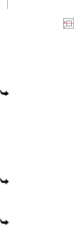
Horizontal Cutline
Horizontal Cutline inserts a horizontal cutline at a specified position into a design.
ART Path automatically inserts horizontal cutlines into a design that exceeds the height limits of the router table. A cutline can also be placed in the design by the user to divide the design for routing. A cutline may also be moved or removed to best suit the design needs using the Move Cutline Tool.
Moving a horizontal cutline cannot result in creating a panel larger than the router will allow. Any cutline the system requires for routing panels cannot be removed. It is recommended to generate a tool path before inserting horizontal cutlines into a design. If the horizontal cutlines are inserted before a tool path is generated the cutlines are deleted from the design and need to be reinserted.
To create a horizontal cutline
1Click Panels > Horizontal Cutline. The mouse pointer changes to a hand with a solid red horizontal line across it that moves as the hand moves.
2Move the horizontal cutline to the desired position.
3Click the left mouse button to secure it.
4Repeat steps 1 through 3 to insert another cutline. The cutlines are numbered in sequence.
Move Cutline 
Move Cutline allows the user to move a horizontal cutline to a different position in a design. A Horizontal Cutline may be moved or removed to best suit the design needs using the Move Cutline feature. Cutlines can also be dragged out of the rulers or created and moved using the tools in the toolbox.
To move a horizontal cutline
1Click Panels > Move Cutline. The mouse pointer changes to a hand.
2Move the tool to the cutline to be moved.
3Click and drag the cutline to the desired position.
4Release the mouse button.
To remove a horizontal cutline
1Click Panels > Move Cutline. The mouse pointer changes to a hand.
2Move the tool to the cutline to be removed.
3Click and drag the cutline off the screen or until it meets another cutline.
4Release the mouse button.
 Loading...