

Page 1

GV-VMS
User's Manual V15.10.1.0
VMSV151010-UM-A
Page 2
© 2016 GeoVision, Inc. All rights reserved.
Under the copyright laws, this manual may not be copied, in whole or in part, without the
written consent of GeoVision.
Every effort has been made to ensure that the information in this manual is accurate.
GeoVision, Inc. makes no expressed or implied warranty of any kind and assumes no
responsibility for errors or omissions. No liability is assumed for incidental or consequential
damages arising from the use of the information or products contained herein. Features and
specifications are subject to change without notice.
GeoVision, Inc.
9F, No. 246, Sec. 1, Neihu Rd.,
Neihu District, Taipei, Taiwan
Tel: +886-2-8797-8377
Fax: +886-2-8797-8335
http://www.geovision.com.tw
Trademarks used in this manual: GeoVision, the GeoVision logo and GV series products are
trademarks of GeoVision, Inc. Windows is the registered trademark of Microsoft Corporation.
February 2016
Page 3
GV-VMS Trial Version
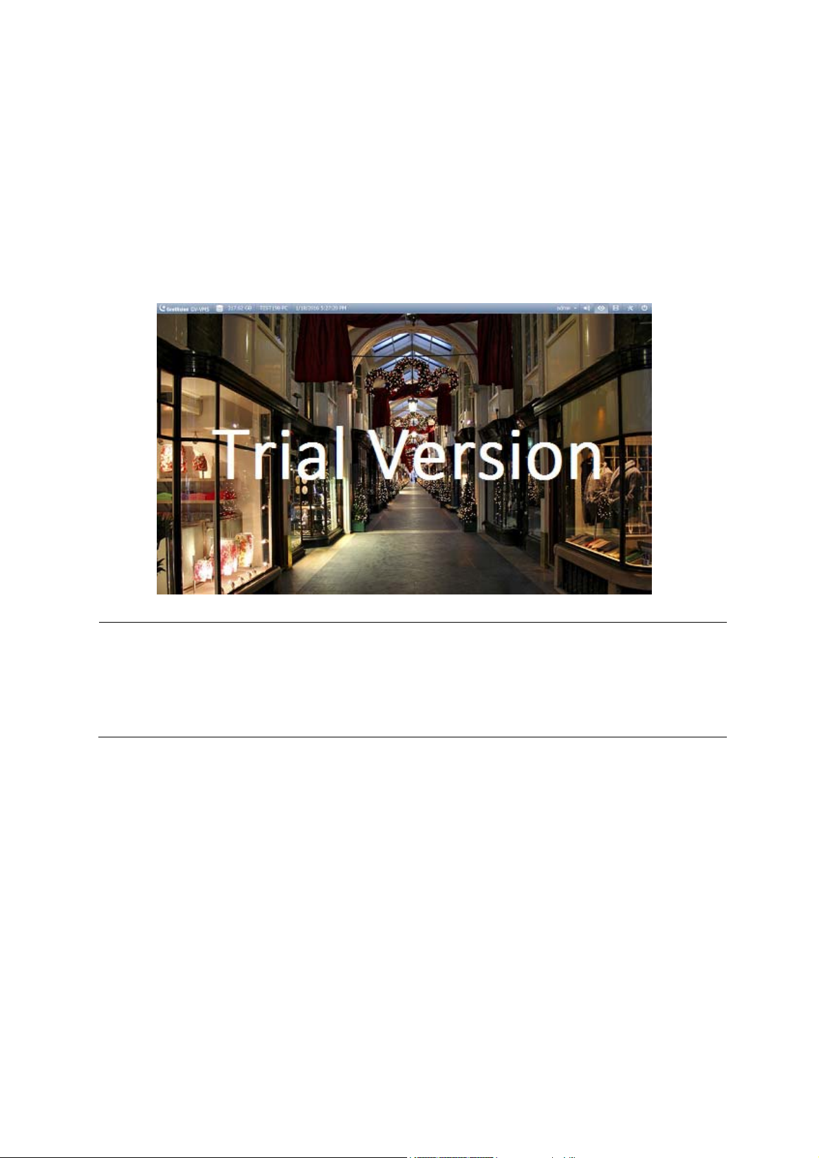
GV-VMS is a comprehensive video management system that records up to 64 channels of
GeoVision and/or third-party IP devices. GeoVision offers a 60-day trial period that allows you to
connect to 16 channels of third-party IP devices without license. A “Trial Version” watermark will
appear on the live view and recorded files for the 16 channels of third-party IP devices.
Note:
1. If you insert a dongle for third-party IP devices, the dongle license will override the trial version
and the 16 trial channels will no longer be supported.
2. Currently, you cannot remotely access the trial channels using remote applications such as
GV-Edge Recording Manager and GV-Control Center…etc.
i
Page 4
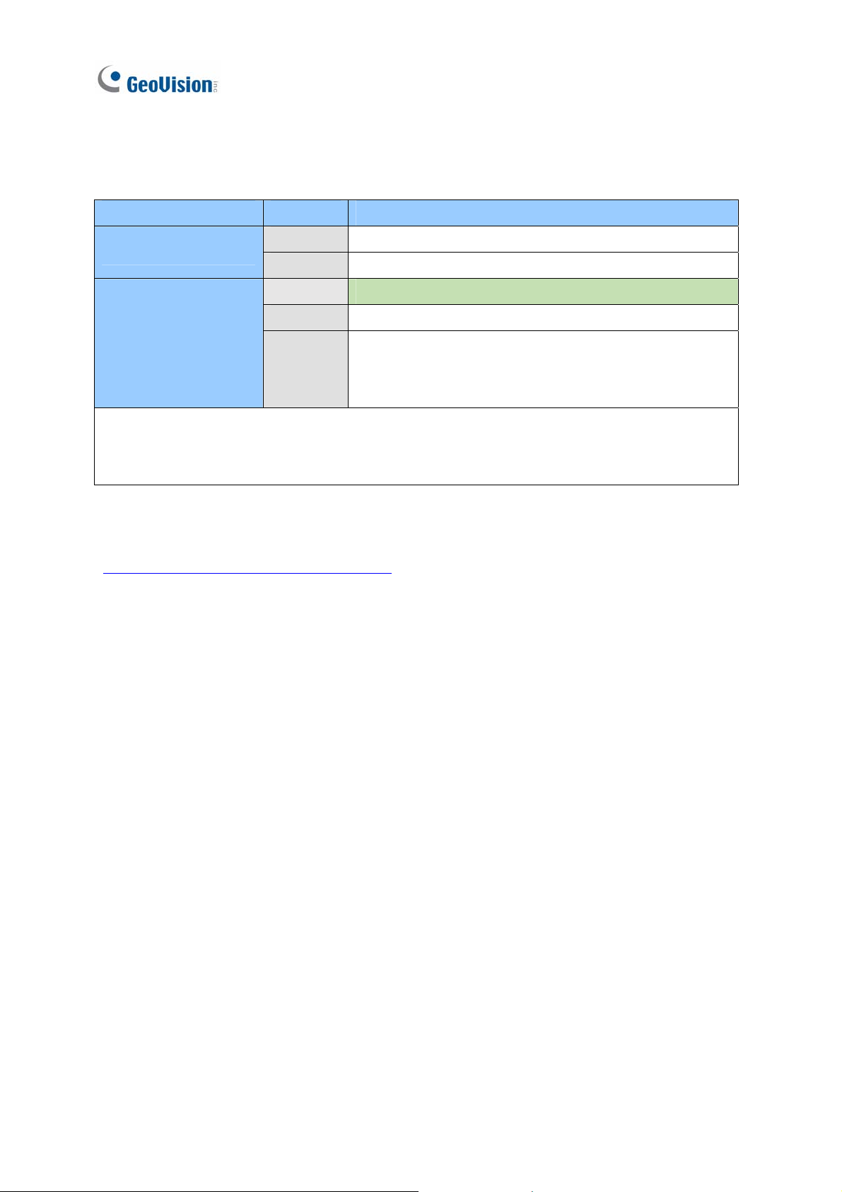
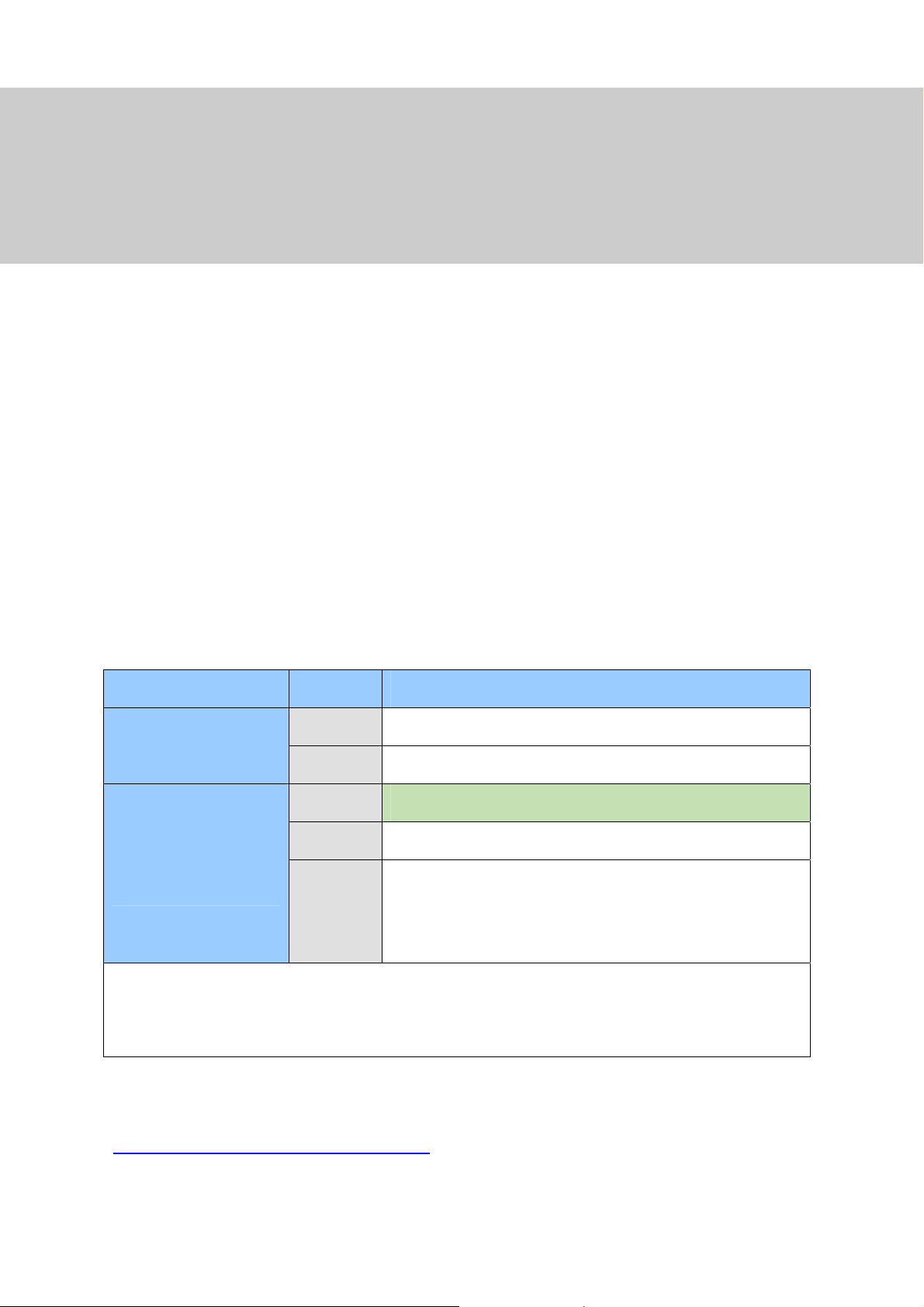
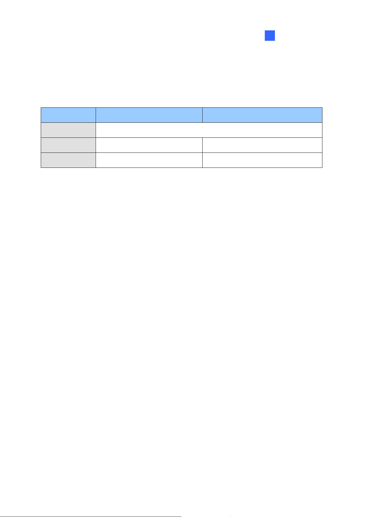
Once the trial period expires, you will need to purchase dongles to connect to third-party IP devices.
The licenses available for purchase are shown below:
Supported Devices Channels License
GV IP Devices Only
GV + 3rd-Party IP
Devices
Note: GV-USB Dongle comes in internal and external dongles. It is recommended to use the internal
GV-USB Dongle to have the Hardware Watchdog function, which restarts the PC when Windows
crashes or freezes.
For the list of supported third-party IP camera models, please visit GeoVision’s website:
http://www.geovision.com.tw/english/4_21.asp
32 ch No license required.
64 ch
16 ch
32 ch
64 ch
GV-VMS Pro license required, 32 ch per license.
Trial Version: 16 channels of 3rd party IP devices.
rd
3
-Party license required, in increments of 1 ch.
2 licenses required:
• GV-VMS Pro license, 32 ch per license.
rd
• 3
-Party license, in increments of 1 ch.
ii
Page 5

Important Notes
GPU Decoding Specifications
GPU (Graphics Processing Unit) decoding can lower the CPU loading and increase the total frame
rate supported by a GV-VMS. GPU decoding can be performed on on-board VGA, external VGA, or
both, under the following specifications.
On-board VGA: GPU decoding is only supported when using the following Intel chipsets:
nd
z 2
z 3
z 4
Generation Intel Core i3 / i5 / i7 Desktop Processors (Sandy Bridge)
rd
Generation Intel Core i3 / i5 / i7 Desktop Processors (Ivy Bridge)
th
Generation Intel Core i3 / i5 / i7 Desktop Processors (Haswell / Haswell Refresh)
z 6th Generation Intel Core i3 / i5 / i7 Desktop Processors (Skylake)
External VGA: GPU decoding is only supported when using NVIDIA graphics cards with compute
capability 3.0 or above and memory 2 GB or above. To look up the commute capability of the NVIDIA
graphics cards, refer to: https://developer.nvidia.com/cuda-gpus
On-board VGA + External VGA: To have both the on-board VGA and external VGA perform GPU
decoding, the VGAs must follow their respective specifications listed above.
Note:
1. If you have both on-board VGA and external VGA installed, the on-board VGA must be connected
to a monitor in order for the on-board VGA to be enabled.
2. You can install multiple external graphics cards if needed.
.
iii
Page 6
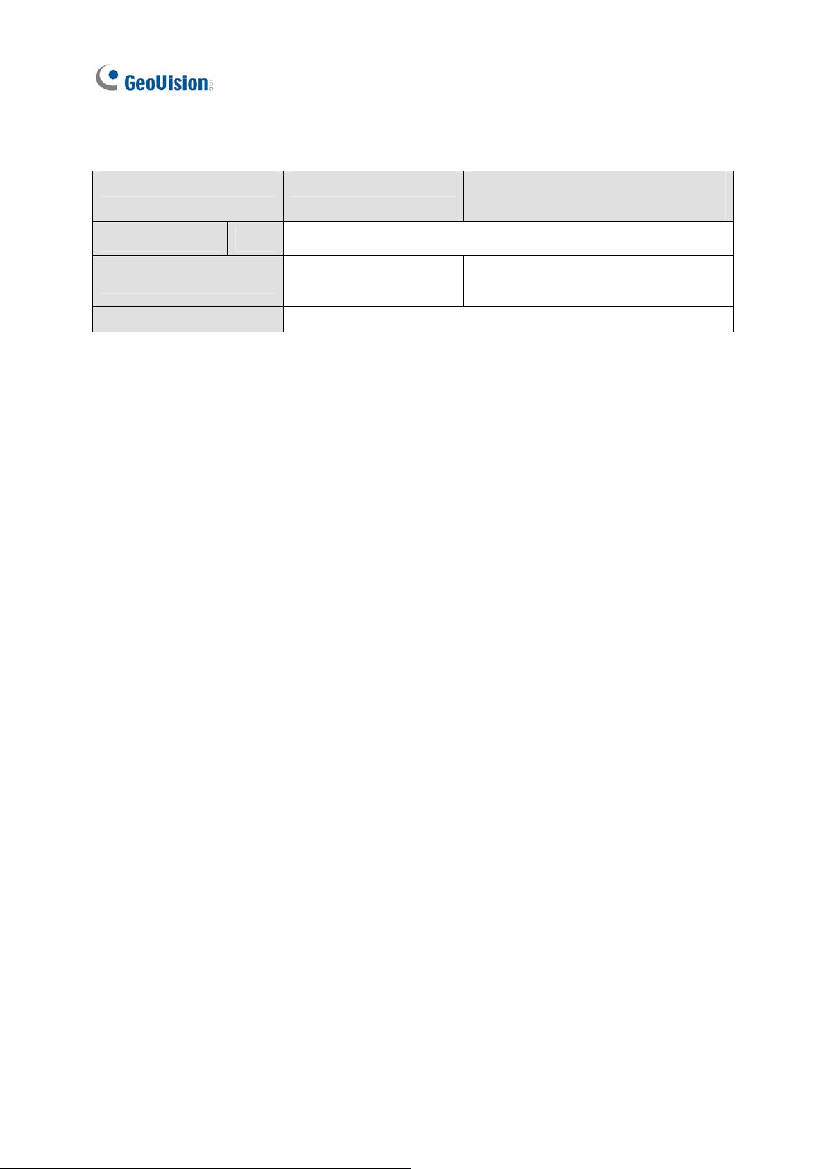
Software Specifications
GPU decoding is only supported under the following operating system, resolution, and codec.
Sandy Bridge Ivy Bridge / Haswell / Haswell Refresh /
Skylake / External VGA (NVIDIA)
Operating System 64-Bit
Resolution
Codec
Windows 7 / 8 / 8.1 / 10 / Server 2008 R2 / Server 2012 R2
1 MP / 2 MP / 3 MP / 4 MP / 5 MP /
1 MP / 2 MP
8 MP / 12 MP
H.264
iv
Page 7

Multi-Channel Playback Specifications
Multi-channel playback in ViewLog has been enhanced to improve the smoothness of the video by
producing higher frame rate. However, playing back multiple channels at high resolution can increase
the CPU loading especially if the GV-VMS is processing other tasks simultaneously. As a result of the
high CPU loading, dropped frames may sometimes occur in recorded video when playing back
multiple megapixel channels.
To avoid the problem, it is recommended to play back megapixel video in single view.
v
Page 8

Contents
GV-VMS Trial Version…………………..........……i
Important Notes…………………................……iii
1
Configuring Main System ............................. 3
1.1 Installing the GV-VMS............................................................................................3
1.1.1 Dongle ..................................................................................................3
1.1.2 Options .................................................................................................4
1.1.3 Recommended System Requirements ................................................5
1.1.4 Minimum Network Requirements .........................................................6
1.1.5 Installing GV-VMS................................................................................7
1.1.6 Uninstalling and Upgrading GV-VMS...................................................9
1.2 Getting Started..................................................................................................... 10
1.2.1 Main Screen ....................................................................................... 11
1.2.2 Adding Cameras.................................................................................13
1.2.3 Accessing Live View........................................................................... 15
1.2.4 Enabling the Recording......................................................................16
1.2.5 Playing Back Video ............................................................................17
1.3 Recording Settings..............................................................................................18
vi
1.3.1 Setting Global Recording Settings for All Cameras ...........................19
1.3.2 Setting Recording Settings for Individual Cameras ...........................21
1.3.3 Setting Up the Video Storage Location..............................................22
1.3.4 Setting Up Motion Detection...............................................................24
1.4 Live View and Layouts ........................................................................................27
1.4.1 Utilizing Live View Functions..............................................................27
1.4.2 Arranging Live View Layouts.............................................................. 30
1.4.3 Setting a Zoom Window .....................................................................33
1.4.4 Setting a Scan Window ......................................................................35
1.4.5 Setting Focus View............................................................................. 37
1.4.6 Automatic Switch among Different Live View Layouts.......................38
1.5 Start Monitoring ...................................................................................................39
Page 9

1.6 System Configuration .........................................................................................41
1.6.1 Configuring General Setting ............................................................... 41
1.6.2 Customizing Startup Settings ............................................................. 43
1.6.3 Customizing Display Position and Panel Resolution ......................... 45
1.6.4 Setting Up Email Notification.............................................................. 46
1.6.5 System Idle Protection ....................................................................... 49
1.6.6 Configuring Fast Key Lock ................................................................. 51
1.7 Account and Password.......................................................................................52
1.7.1 Creating a New Account..................................................................... 53
1.7.2 Configuring Account Settings ............................................................. 54
1.7.3 Changing or Retrieving Password at Login........................................ 56
1.7.4 Preventing Unauthorized System Termination................................... 57
1.7.5 Setting a Startup Auto Login User...................................................... 58
1.8 Schedule...............................................................................................................59
1.8.1 Creating a Schedule with Setup Wizard............................................. 60
2
1.8.2 Creating a Schedule Manually ...........................................................63
1.8.3 Exporting and Importing Schedule Settings ....................................... 64
1.9 System Log .......................................................................................................... 65
1.9.1 Setting System Log ............................................................................65
1.9.2 Viewing System Log........................................................................... 67
1.10 Other Functions.................................................................................................69
1.10.1 Setting Live View Pop-Up Video ......................................................69
1.10.2 Adjusting to Daylight Saving Time ...................................................70
1.10.3 Setting Network Failure Detection.................................................... 71
1.11 PTZ Camera........................................................................................................ 72
1.11.1 Accessing PTZ Control Panel and Auto Functions .......................... 73
1.11.2 Setting PTZ Idle Protection and Advanced Functions .....................75
IP Camera Setup .................................78
2.1 Adding IP Cameras.............................................................................................. 78
2.1.1 Adding Cameras Manually .................................................................80
2.1.2 Scanning Camera............................................................................... 83
2.1.3 Mapping GV-IP Cameras Using GV-IP Device Utility ........................ 84
2.2 Configuring Individual IP Cameras....................................................................86
vii
Page 10

2.2.1 Configuring Video Setting................................................................... 86
2.2.2 Configuring Audio Setting................................................................... 89
2.2.3 Configuring General Setting ............................................................... 90
2.3 Connection through RTSP, ONVIF & PSIA........................................................92
2.4 On Demand Display............................................................................................. 95
3
Video Analysis ....................................99
3.1 Object Counting and Intrusion Alarm................................................................99
3.1.1 Object Counting.................................................................................. 99
3.1.2 Intrusion Alarm ................................................................................. 103
3.2 Object Index .......................................................................................................108
3.2.1 Setting Object Index ......................................................................... 108
3.2.2 Viewing Object Index........................................................................ 111
3.2.3 Searching Object Index .................................................................... 112
3.3 Automatic Video Snapshots .............................................................................114
3.3.1 Setting Video Snapshots .................................................................. 114
3.3.2 Searching Video Snapshots ............................................................. 117
3.4 Face Detection ................................................................................................... 119
3.4.1 Setting Face Detection ..................................................................... 119
3.4.2 Searching Face Detection Snapshots .............................................. 121
3.5 Face Count .........................................................................................................122
viii
3.5.1 Installing the Camera ....................................................................... 122
3.5.2 Setting Face Count........................................................................... 123
3.6 Privacy Mask Protection ...................................................................................127
3.6.1 Setting a Privacy Mask ..................................................................... 127
3.6.2 Granting Access Privileges to Recoverable Areas .......................... 129
3.7 Panorama View ..................................................................................................130
3.7.1 The Main Window............................................................................. 130
3.7.2 Stitching a Panorama View with Overlapping Areas........................ 132
3.7.3 Easy Mode with No Overlapping Area .............................................135
3.7.4 Accessing a Panorama View ...........................................................138
3.8 Video Defogging ................................................................................................139
3.9 Video Stabilization............................................................................................. 141
3.10 Wide Angle Lens Dewarping ..........................................................................143
Page 11

3.11 Advanced Motion Detection ...........................................................................145
3.12 Crowd Detection ..............................................................................................148
3.13 Advanced Scene Change Detection..............................................................151
3.14 Advanced Unattended Object Detection.......................................................154
3.15 Advanced Missing Object Detection .............................................................157
3.16 Text Overlay .....................................................................................................160
3.17 Fisheye View ....................................................................................................162
3.17.1 Setting Up a GV-Fisheye Camera.................................................. 163
3.17.2 Setting Up a Third-Party Fisheye Camera .....................................166
3.17.3 Object Tracking .............................................................................. 168
3.18 Specifications .................................................................................................. 175
3.19 Heat Map........................................................................................................... 178
3.19.1 Enabling Heat Map......................................................................... 178
3.19.2 Object Tracking .............................................................................. 182
3.20 PTZ Object Tracking........................................................................................183
4
3.20.1 Dual Camera Tracking ...................................................................183
3.20.2 Single Camera Tracking................................................................. 186
3.21 Specifications .................................................................................................. 188
Video Playback........................................ 191
4.1 Playing Back on ViewLog.................................................................................192
4.1.1 ViewLog Control Panel..................................................................... 194
4.1.2 Adjusting the Camera View .............................................................. 197
4.1.3 Searching a Video Event.................................................................. 198
4.1.4 Bookmarking Video Events in ViewLog ........................................... 199
4.1.5 Merging and Exporting Video........................................................... 200
4.1.6 Saving Images.................................................................................. 204
4.1.7 Printing Images ................................................................................ 205
4.1.8 Adjusting Distorted Views................................................................. 206
4.2 Object Search.....................................................................................................208
4.3 Advanced Log Browser ....................................................................................210
4.3.1 Filter Settings ................................................................................... 212
4.4 Remote ViewLog Service ..................................................................................213
4.4.1 Retrieving Recordings from GV-VMS ..............................................213
ix
Page 12
4.4.2 Retrieving Images of Object Index ...................................................215
4.4.3 Resuming Backup ............................................................................ 216
4.5 Single Player ......................................................................................................217
4.5.1 Single Player Window ...................................................................... 217
4.6 Specifications .................................................................................................... 218
5
6
Backup, Deletion and Repair ................... 220
5.1 Backing Up Log Data.........................................................................................220
5.2 Backing Up Recorded Files..............................................................................222
5.3 Deleting Recorded Files.................................................................................... 225
5.4 Repairing Damaged File Paths......................................................................... 227
5.5 Repairing Damaged Video Files.......................................................................229
I/O Applications ........................................ 232
6.1 Setting I/O Devices ............................................................................................233
6.1.1 Adding I/O Devices........................................................................... 234
6.1.2 Setting the Input and Output Devices ..............................................235
6.1.3 Latch Trigger .................................................................................... 237
6.1.4 Keeping Last Toggle Status .............................................................239
6.2 Advanced I/O Applications ...............................................................................241
6.2.1 Setting Up Actions Upon Input Trigger............................................. 242
6.2.2 Moving PTZ Camera to Preset Points upon Input Trigger ...............243
6.2.3 Setting Momentary and Maintained Modes...................................... 244
6.2.4 Deactivating Alarm and Alert upon Input Trigger ............................. 245
6.2.5 Other I/O Application Functions .......................................................246
6.3 I/O Devices in Content List...............................................................................247
6.4 Visual Automation .............................................................................................248
x
Page 13

7
Remote Viewing............................................ 252
7.1 Remote Viewing Using a Web Browser...........................................................253
7.2 WebCam Server Settings.................................................................................. 257
7.2.1 General Settings............................................................................... 257
7.2.2 Server Settings .................................................................................259
7.2.3 Video Settings .................................................................................. 260
7.2.4 Audio Settings .................................................................................. 261
7.2.5 JPG Settings .................................................................................... 263
7.2.6 UPnP Settings ..................................................................................264
7.2.7 Network Port Information.................................................................. 265
7.3 Single View Viewer........................................................................................266
7.3.1 Adjusting Video Quality and Recording Videos................................ 268
7.3.2 Control Panel.................................................................................... 269
7.3.3 Configuring Single View Viewer Options.......................................... 270
7.3.4 PTZ Control Panel............................................................................ 275
7.3.5 Visual PTZ Control ........................................................................... 276
7.3.6 I/O Control ........................................................................................277
7.3.7 Visual Automation ............................................................................ 278
7.3.8 Picture-in-Picture View ..................................................................... 279
7.3.9 Picture-and-Picture View.................................................................. 280
7.4 2-Window Viewer ...............................................................................................281
7.5 Multi-Window Viewer......................................................................................... 282
7.6 JPEG Image Viewer ...........................................................................................283
7.7 Playing Back Events..........................................................................................284
7.7.1 Event List Query............................................................................... 284
7.7.2 Remote Playback ............................................................................. 285
7.8 Remote ViewLog................................................................................................ 287
7.9 Download Center ...............................................................................................288
7.10 GV-Edge Recording Manager .........................................................................289
7.11 Mobile Phone Applications.............................................................................291
7.11.1 Activating Mobile Functions on GV-VMS .......................................291
7.11.2 Installing GV-Eye............................................................................ 293
7.11.3 Connecting to GV-VMS .................................................................. 294
7.12 Web Browsers on Smartphones ....................................................................296
xi
Page 14
8
E-Map Application......................................... 299
8.1 The E-Map Editor ...............................................................................................299
8.1.1 The E-Map Editor Window ...............................................................300
8.1.2 Creating an E-Map ........................................................................... 301
8.1.3 Creating an E-Map for a Remote Host............................................. 306
8.2 Starting E-Map....................................................................................................307
8.2.1 Setting Up the Pop-up Map .............................................................. 309
8.3 Remotely Accessing E-Map.............................................................................. 311
8.3.1 The Remote E-Map Window ............................................................ 312
8.3.2 Accessing E-Maps of Multiple Hosts ................................................ 314
8.3.3 Configuring the Remote E-Map........................................................ 315
8.3.4 Viewing Event List and Playing Back Videos ................................... 317
8.4 E-Map Server......................................................................................................318
8.4.1 Installing E-Map Server ....................................................................318
8.4.2 The E-Map Server Window .............................................................. 319
9
8.4.3 Setting up E-Map Server .................................................................. 320
8.4.4 Connecting to E-Map Server ............................................................ 320
Useful Utilities…………………………………………323
9.1 Dynamic DNS .....................................................................................................323
9.1.1 Running Dynamic DNS .................................................................... 324
9.1.2 Registering Domain Name with DDNS ............................................325
9.1.3 Starting Dynamic DNS ..................................................................... 327
9.2 Watermark Viewer..............................................................................................329
9.2.1 Activating Watermark Protection ...................................................... 329
9.2.2 Running the Watermark Proof.......................................................... 330
9.2.3 The Main Window............................................................................. 331
9.3 Windows Lockup ...............................................................................................332
9.3.1 The GV-Desktop Screen ..................................................................332
9.3.2 GV-Desktop Features....................................................................... 333
9.3.3 Token File for Safe Mode ................................................................. 336
xii
Page 15

9.4 Authentication Server ....................................................................................... 337
9.4.1 Installing the Server.......................................................................... 337
9.4.2 The Main Window............................................................................. 338
9.4.3 Creating Clients ................................................................................ 340
9.4.4 Creating User Accounts ...................................................................341
9.4.5 Importing Groups and Users from Active Directory .........................345
9.4.6 Starting the Server ...........................................................................349
9.4.7 Connecting GV-VMS to the Server .................................................. 351
9.4.8 Remote Access from Control Center and Remote E-Map ............... 354
9.5 Fast Backup and Restore .................................................................................357
9.5.1 Running the FBR Program ............................................................... 357
9.5.2 Plugin Component ............................................................................ 358
9.5.3 Customizing the Features ................................................................ 359
9.5.4 Backing up and Restoring Settings .................................................. 360
9.6 Bandwidth Control Application........................................................................364
9.6.1 Installing the Bandwidth Control....................................................... 365
9.6.2 The Main Window............................................................................. 366
9.6.3 Allowing Remote Control.................................................................. 367
9.6.4 Connecting to a WebCam Server .................................................... 368
9.6.5 Controlling Specific WebCam Server............................................... 369
9.6.6 Setting up the Bandwidth .................................................................370
9.6.7 Block List Setup................................................................................ 371
9.6.8 General Setup .................................................................................. 372
9.7 Language Setting............................................................................................... 373
9.7.1 Installing the MultiLang Tool............................................................. 373
9.7.2 Revising the Translated Text............................................................ 374
9.7.3 Setting Up the UI Language to English ............................................ 378
9.8 Skype Video Utility ............................................................................................380
9.8.1 Installing GV-Skype Video Utility...................................................... 381
9.8.2 Setting Up Notifications Upon Motion or I/O Trigger ........................ 382
9.8.3 Requesting Live View....................................................................... 387
9.9 GV-SDSyncCard Utility...................................................................................... 388
9.9.1 Installing GV-SDCardSync Utility ..................................................... 388
9.9.2 Setting Up GV-SDCardSync Utility ..................................................389
9.9.3 The Main Window............................................................................. 392
9.10 The Media Man Tools Window........................................................................394
9.10.1 The Media Man Tools Window....................................................... 394
9.10.2 Viewing Disk Drive Status ..............................................................395
xiii
Page 16

9.10.3 Adding a Disk Drive ........................................................................ 397
9.10.4 Removing a Disk Drive ...................................................................398
9.10.5 Logging In Automatically at Startup ...............................................399
9.10.6 Setting LED Panel ..........................................................................399
9.11 Alert Notifications Through SNMP Protocol.................................................402
xiv
Page 17

Chapter 1
Configuring Main System ....................... 3
1.1 Installing the GV-VMS.......................................................................... 3
1.1.1 Dongle ..................................................................................................................3
1.1.2 Options ................................................................................................................ 4
1.1.3 Recommended System Requirements ...................................................... 5
1.1.4 Minimum Network Requirements ...............................................................6
1.1.5 Installing GV-VMS ............................................................................................7
1.1.6 Uninstalling and Upgrading GV-VMS......................................................... 9
1.2 Getting Started ....................................................................................10
1.2.1 Main Screen .....................................................................................................11
1.2.2 Adding Cameras ............................................................................................. 13
1.2.3 Accessing Live View..................................................................................... 15
1.2.4 Enabling the Recording ............................................................................... 16
1.2.5 Playing Back Video ....................................................................................... 17
1.3 Recording Settings.............................................................................
1.3.1 Sett ing Global Recording Settings for All C amer as...........................
18
19
1.3.2 Sett ing Recording Settings for Individual C ameras ..........................
1.3.3 Setting Up the Video Storage Locat ion .................................................
1.3.4 Setting Up Motion Detection .....................................................................
1.4 Live View and Layouts......................................................................
1.4.1 Utilizing Live View Functions ....................................................................
1.4.2 Arranging Live View Layouts .....................................................................
1.4.3 Setting a Zoom Window...............................................................................
1.4.4 Setting a Scan Window ................................................................................
1.4.5 Setting Focus View .......................................................................................
1.4.6 Automatic Swit ch among Different Live View L ayouts....................
1.5 Start Monitoring ..................................................................................
1.6 System Configuration ........................................................................
1.6.1 Configuring General Setting.......................................................................
1.6.2 Customizing Startup Settings....................................................................
1.6.3 Customizing Display Position and Panel Resolut ion .........................
1.6.4 Setting Up Email Notification....................................................................
21
22
24
27
27
30
33
35
37
38
39
41
41
43
45
46
1.6.5 System Idle Protection ................................................................................
1.6.6 Configuring Fast Key Lock .........................................................................
49
51
1
Page 18

1.7 Account and Password .....................................................................
52
1.7.1 C r eating a New Account .............................................................................
1.7.2 Configuring Account Settings ...................................................................
1.7.3 C hanging or Retrieving Password at Login ..........................................
1.7.4 Preventing Unauthorized System Termination....................................
1.7.5 Setting a Startup Auto Login User...........................................................
1.8 Schedule ................................................................................................
1.8.1 Creating a Schedule with Setup Wizar d ................................................
1.8.2 Creating a Schedule Manually...................................................................
1.8.3 Exporting and Importing Schedule Settings ........................................
1.9 System Log ...........................................................................................
1.9.1 Setting System Log .......................................................................................
1.9.2 Viewing Sys tem Log .....................................................................................
1.10 Other Functions ................................................................................
1.10.1 Setting Live View Pop-Up Video.............................................................
1.10.2 Adjusting to Daylight Saving Time........................................................
1.10.3 Setting Network Failure Detection.......................................................
53
54
56
57
58
59
60
63
64
65
65
67
69
69
70
71
1.11 PTZ Camera........................................................................................
1.11.1 Accessing PTZ Cont rol Panel and Aut o Functions..........................
1.11.2 Setting PTZ Idle Protection and Advanced Functions...................
72
73
75
2
Page 19
CHAPTER
Configuring Main System
1.1 Installing the GV-VMS
1.1.1 Dongle
1
GV-VMS supports connection with up to connection with up to 64 IP devices. You can connect up to 32
channels of GV-IP Devices for free. If you need to connect more than 32 channels of GV-IP Devices or
connect with third-party IP devices, license is required.
Supported Devices Channels License
32 ch No license required.
GV IP Devices Only
64 ch
16 ch
32 ch
GV + 3rd-Party IP
Devices
64 ch
Note: GV-USB Dongle comes in internal and external dongles. It is recommended to use the internal
GV-USB Dongle to have the Hardware Watchdog function, which restarts the PC when Windows
GV-VMS Pro license required, 32 ch per license.
Trial Version: 16 channels of 3rd party IP devices.
rd
3
-Party license required, in increments of 1 ch.
2 licenses required:
• GV-VMS Pro license, 32 ch per license.
rd
• 3
-Party license, in increments of 1 ch.
crashes or freezes.
For the list of supported third-party IP camera models, please visit GeoVision’s website:
http://www.geovision.com.tw/english/4_21.asp
3
Page 20
1.1.2 Options
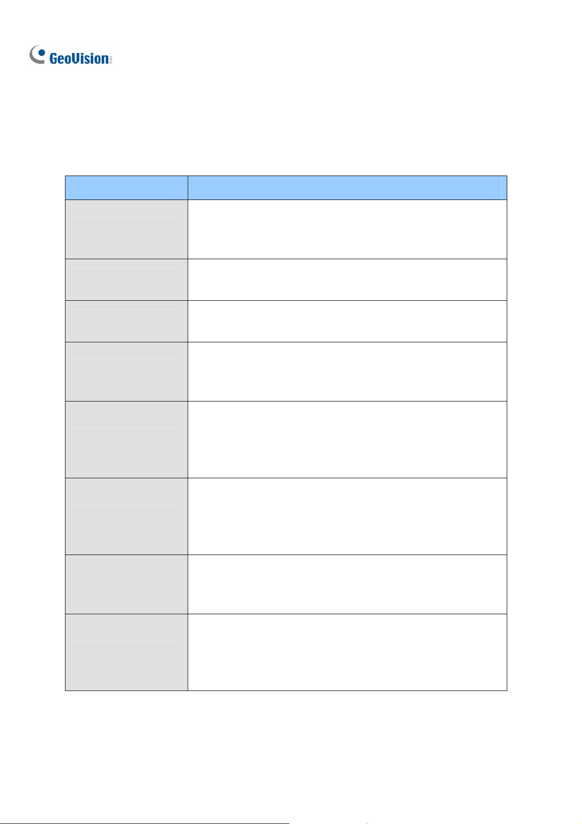
The following optional devices are available to expand your GV-VMS’s capabilities and versatility.
Contact your dealer for more information.
Optional Devices Description
The USB dongle can provide the Hardware Watchdog function to the
Internal USB Dongle
GV-Hub V2
GV-COM V2
GV-IO Box (4 Ports)
GV-IO Box (8 Ports)
GV-IO Box (16 Ports)
GV-VMS by restarting the computer when Windows crashes. You need
to connect the dongle internally on the motherboard.
An easy way for serial port extension, this hub can add 4 RS-232 /
RS-485 serial ports through the GV-VMS’s USB port.
GV-COM V2 can add 1 RS-232 / RS-485 serial port through the
GV-VMS’s USB port.
GV-IO Box 4 Ports provides 4 inputs and 4 relay outputs, and supports
both DC and AC output voltages. A USB port is also provided for PC
connection.
GV-IO Box 8 Ports provides 8 inputs and 8 relay outputs, and supports
both DC and AC output voltages. You can connect the unit to the PC
either by using its USB port or through network by using its Ethernet
module.
GV-IO Box 16 Ports provides 16 inputs and 16 relay outputs, and
supports both DC and AC output voltages. You can connect the unit to
the PC either by using its USB port or through network by using its
GV-Joystick V2
GV-Keyboard V3
4
Ethernet module.
GV-Joystick V2 allows you to easily control PTZ cameras. It can be
either plugged into the GV-VMS for independent use or connected to
GV-Keyboard.
GV-Keyboard V3 is used to program and operate GV-VMS and PTZ
cameras. Through RS-485 configuration, it can control up to 36
GV-VMS. In addition, you can connect PTZ cameras directly to the
keyboard for PTZ control.
Page 21
Configuring Main System
1
1.1.3 Recommended System Requirements
Below are the recommended PC requirements for connecting GV-VMS with 32 and 64 channels of GV
and 3rd party IP cameras (dual streams).
GV -VMS (Up to 32 Channels) GV-VMS Pro (Up to 64 Channels)
OS
CPU
Memory
64-bit Windows 7 / 8 / 8.1 / 10 / Server 2008 R2 / Server 2012 R2
4th Generation i3-4130, 3.4 GHz 4th Generation i7-4770, 3.4 GHz
8 GB RAM 16 GB RAM
5
Page 22
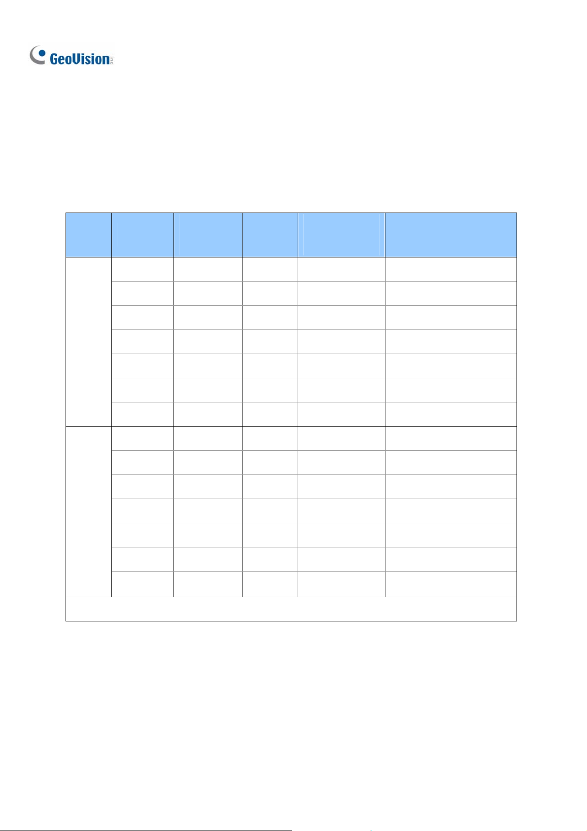
1.1.4 Minimum Network Requirements
The data transmitting capacity of GV-VMS depends on the number of Gigabit connections available.
The numbers of Gigabit network cards required to connect 64 channels are listed below according to
the resolution and codec of the source video.
Codec Resolution
1.3 MP
2 MP
3 MP
H.264
MJPEG
4 MP
5 MP
8 MP
12 MP
1.3 MP
2 MP
3 MP
4 MP
Bitrate Used
(Mbps)
5.05 1920 1 Max. 64 ch / card
7.01 1920 1 Max. 64 ch / card
10.48 1280 1 Max. 64 ch / card
11.65 960 2 Max. 50 ch / card
16.48 640 2 Max. 38 ch / card
17.14 1600 2 Max. 38 ch / card.
16.67 960 2 Max. 38 ch / card
32.36 1920 3 Max. 22 ch / card
44.96 1920 4 Max. 16 ch / card
38.73 1280 4 Max. 18 ch / card
40.35 960 4 Max. 17 ch / card
Total FPS
for 64 ch
Gigabit Network
Cards Required
Max. Channels Supported
per Network Card
5 MP
8 MP
12 MP
Note: The network requirements may vary depending on the bit rate of the streams.
6
30.48 640 3 Max. 22 ch / card
58.52 1600 6 Max. 12 ch / card
65.98 960 6 Max. 11 ch / card
Page 23
Configuring Main System
1
1.1.5 Installing GV-VMS
Before You Start
For optimal performance of your system, it is important to follow these recommendations before
installing the GV-VMS:
• It is strongly recommended to use separate hard disks. One is for installing Windows OS and
GV-VMS software, and the other is for storing recorded files and system logs.
• When formatting the hard disks, select NTFS as the file system.
• GV-VMS is a multi-channel video recording system. With normal use of the system, the drive
containing video files will become fragmented. This is because GV-VMS constantly stores video
files of multi channels simultaneously, and video files will be scattered all over the drive. It is not
necessary to regularly perform disk defragmentation. Since GV-VMS software and video files are
stored on separated hard disks, the performance of GV-VMS will not be affected.
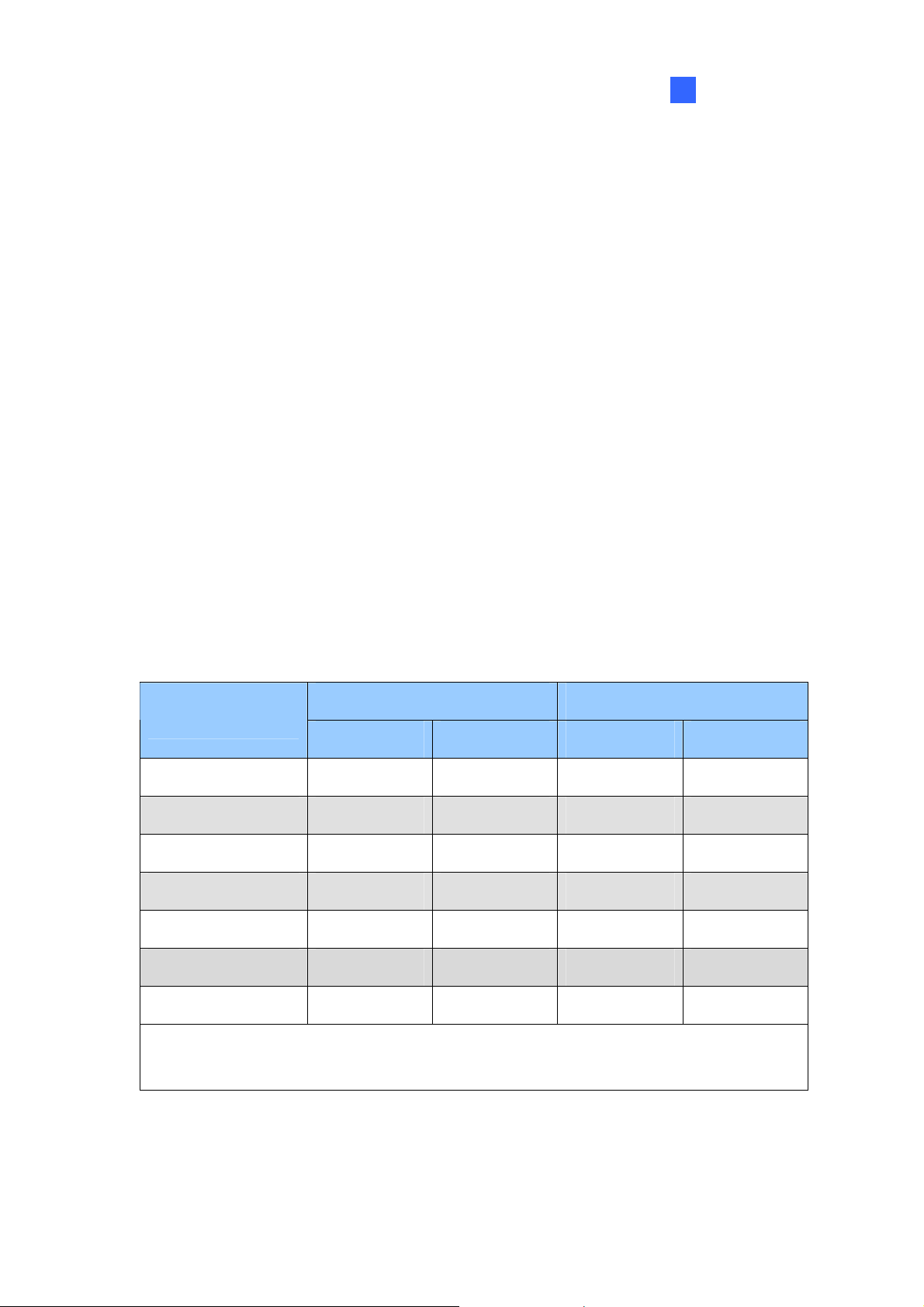
• Since the size of transmitted data from IP cameras may be quite large and reach beyond the
transfer rate of a hard disk, you should note the total of recording frame rates that you can assign
to a single hard disk, as listed below:
Frame rate limit in a single hard disk
H.264 MJPEG
Video Resolution
Frame Rate Bit Rate Frame Rate Bit Rate
1.3 MP (1280 x 1024) 660 fps 5.05 Mbit/s 300 fps 32.26 Mbit/s
2 MP (1920 x 1080) 660 fps 7.01 Mbit/s 210 fps 44.93 Mbit/s
3 MP (2048 x 1536) 440 fps 10.48 Mbit/s 140 fps 38.67 Mbit/s
4 MP (2048 x 1944) 330 fps 11.65 Mbit/s 105 fps 40.53 Mbit/s
5 MP (2560 x 1920) 220 fps 16.48 Mbit/s 80 fps 30.4 Mbit/s
8 MP (3840 x 2120) 660 fps 14.13 Mbit/s 96 fps 58.52 Mbit/s
12 MP (4000 x 3000) 330 fps 14.47 Mbit/s 56 fps 65.98 Mbit/s
Note: The data above was determined using the bit rate listed above and hard disks with
average R/W speed above 110 MB/s.
7
Page 24
Installing GV-VMS
1. To download GV-VMS, go to the Software Download and Upgrading page of GeoVision Website:
The frame rate limit is based on the resolution of video sources. The higher video resolutions, the
lower frame rates you can assign to a single hard disk. In other words, the higher frame rates you
wish to record, the more hard disks you need to install. For the information of recording frame
rates, you may consult the user’s manual of the IP camera that you wish to connect to.
http://www.geovision.com.tw/english/5_8_VMS.asp
2. To install GV-VMS, find the Primar y Applicat ion s section under the Video Management Software
tab and click the Download icon
3. Double-click GVVMSInstaller.exe and follow the instructions in the wizard to complete installation.
4. If you are using a USB dongle, insert the dongle to your computer. The GV-USB dongle is needed
if you want to connect to more than 32 channels of IP devices or to third-party IP devices.
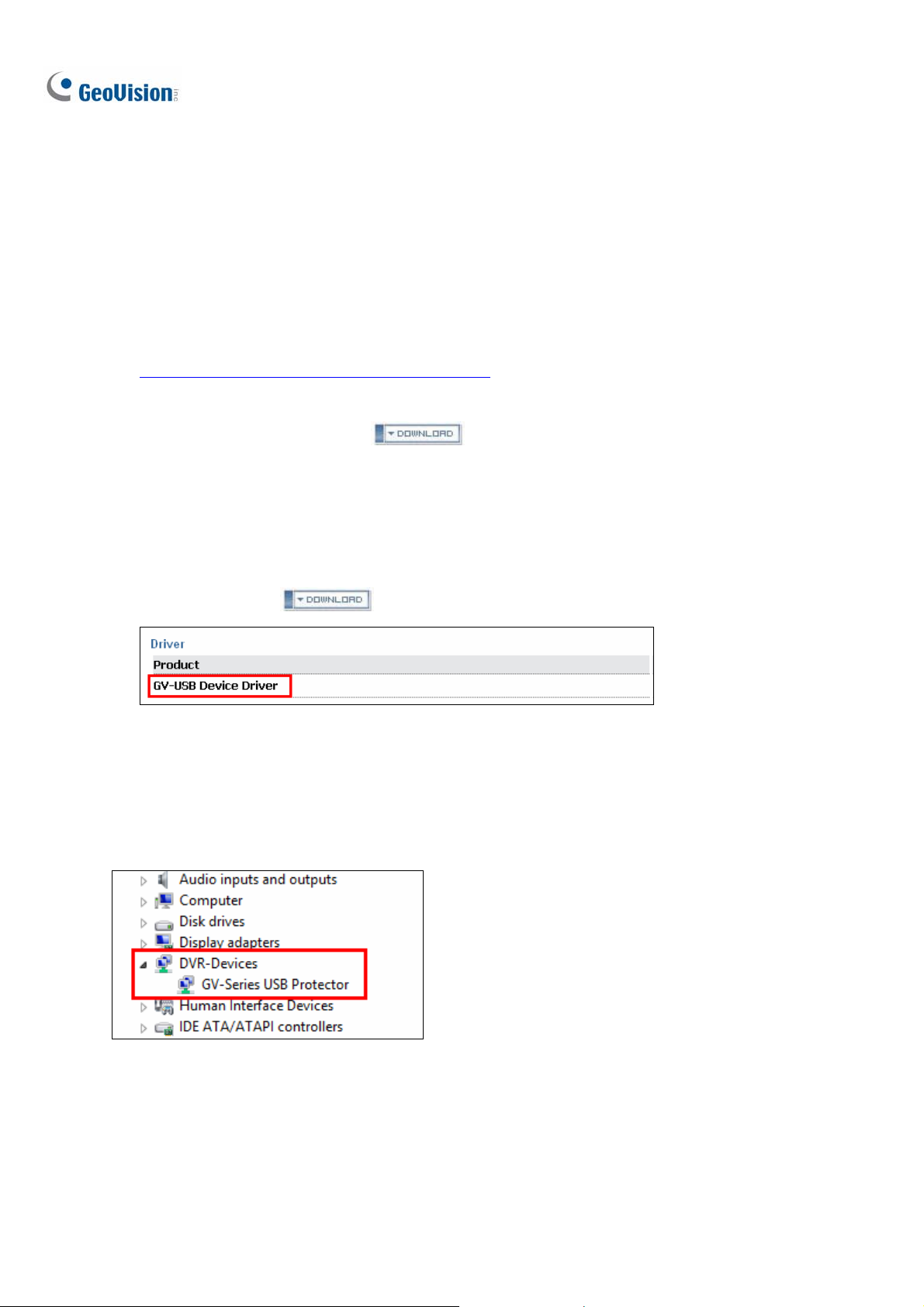
5. To install USB driver, find the Driver section under the Video Management Software tab, and click
the Download icon
If you are using the GV-USB dongle, verify that the driver is installed correctly after the steps above.
Go to Windows Device Manager and expand DVR-Devices. You should see the GV-Series USB
of GV-USB Devices Driver.
Figure 1-1
.
of GV-VMS.
Protector.
8
Figure 1-2
Page 25
Configuring Main System
1
1.1.6 Uninstalling and Upgrading GV-VMS
GeoVision will periodically release software updates on our website. Before installing software
upgrade, be sure to uninstall GeoV ision Sof tware fir st. By default, GeoVision software and log files
are stored on one drive, while video files are stored on a different drive. Uninstalling GV-VMS will not
remove the video, log, and setting files previously saved in the computer.
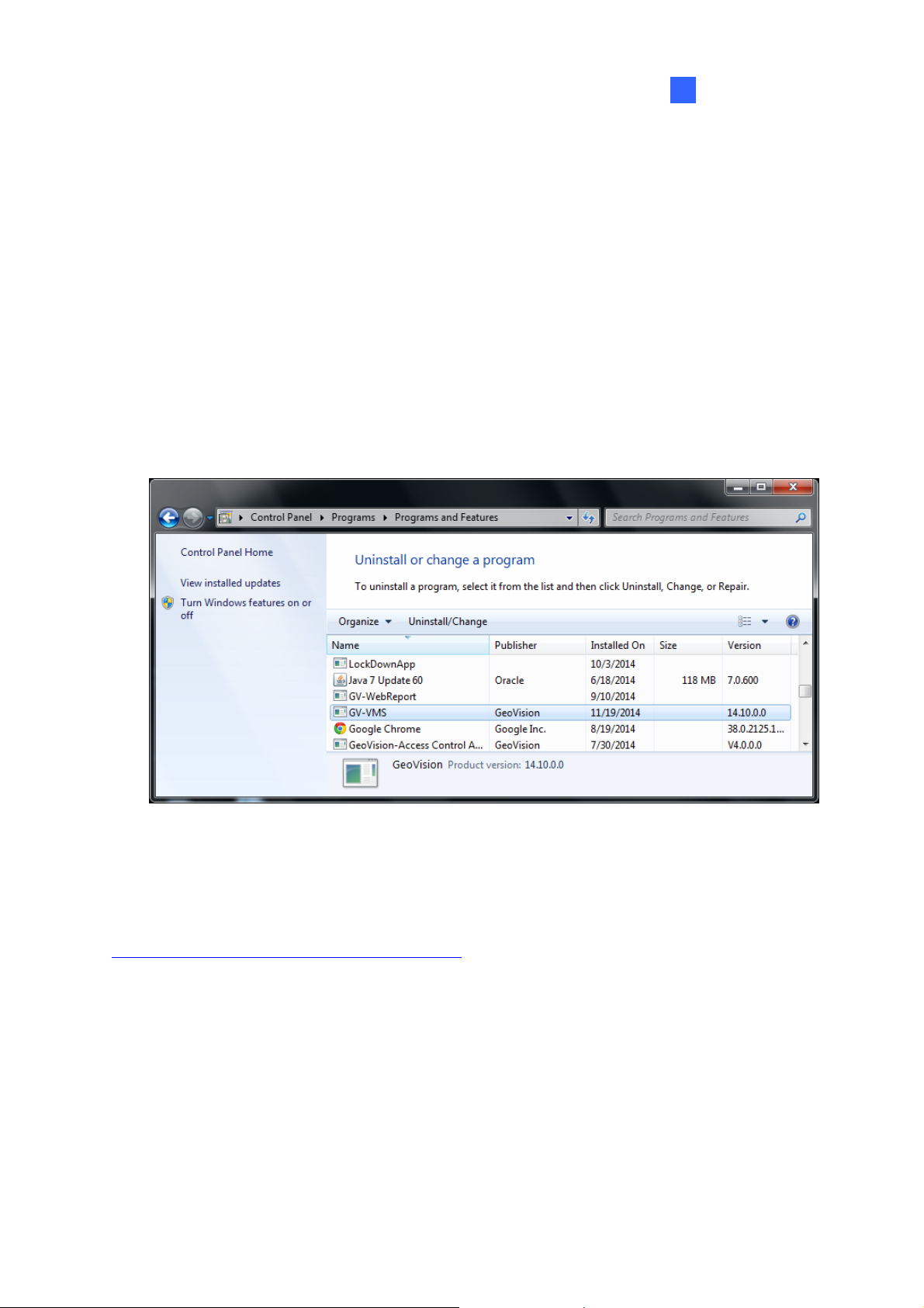
To uninstall the GV-VMS, follow these steps:
1. Close any open programs because your computer will restart during the uninstalling process.
2. Click the Start button, click Control Panel, and then click Uninstall a Program under Programs.
3. In the list of currently installed programs, select GV-VMS, and then click Uninstall/Change.
Figure 1-3
4. When you are prompted to confirm the program removal, click Yes.
To upgrade, download the newest GV-VMS from GeoVision’s website and re-install on your computer:
http://www.geovision.com.tw/english/5_8_VMS.asp
.
9
Page 26
1.2 Getting Started
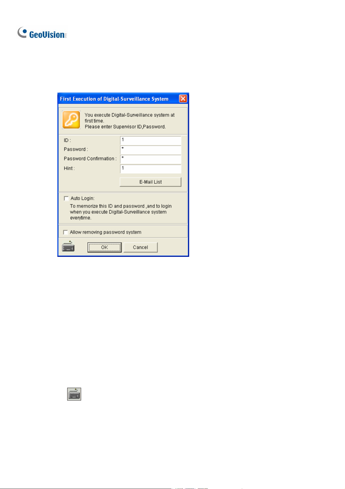
When you run GV-VMS for the first time, the system will prompt you for a Supervisor ID and Password.
Figure 1-4
1. Type an ID and a password. Type the password again for confirmation.
2. Type a hint that would remind you of the password.
3. It is recommended to click E-Mail List and enter e-mail addresses. When you forget the
password, the password can be sent to your e-mail account.
4. Click OK to enter the main screen. You can also select the following options:
Auto Login: Allows auto login as the current user every time when the system is launched.
For security purposes, this feature is only recommended for single-user systems.
Allow removing password System: It is recommended to select this option which allows
removing the password database once you forget passwords. For details, see the same
option in Account and Password later in this chapter.
: Click to open the onscreen keyboard and enter the login information.
10
Page 27
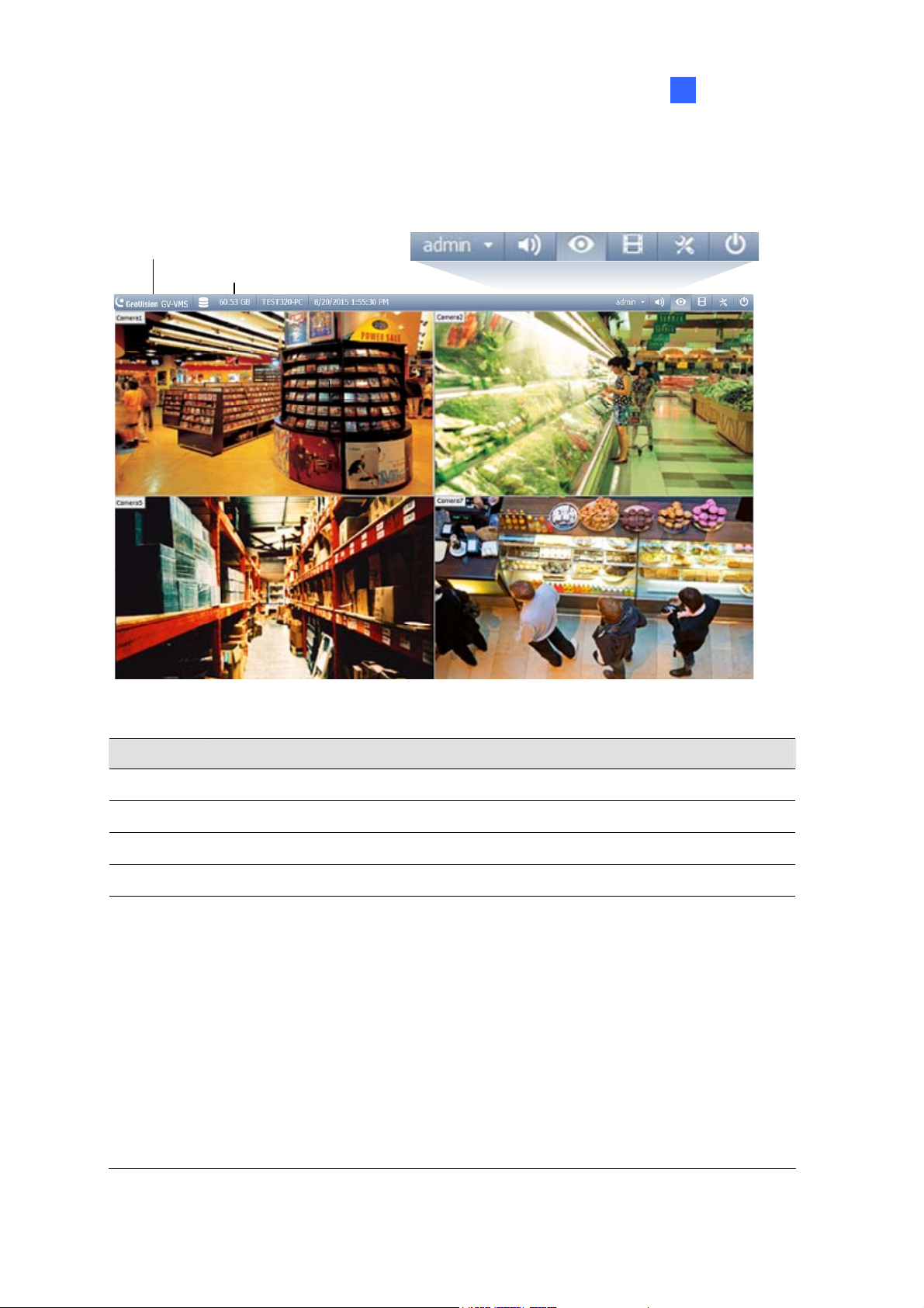
1.2.1 Main Screen
Configuring Main System
1
Version Information
St orage Space
Audio
Home
ViewLog
ToolbarLogin ID
Exit
Figure 1-5
Name Description
Login ID Click to manage accounts and passwords for accessing GV-VMS.
Audio Click to control the volume of your PC.
Home Shows the live view of connected cameras.
ViewLog Shows a timeline of recorded events for playback.
Brings up these options when Home is selected:
• Monitor: Start / Stop monitoring, I/O monitoring and schedule monitoring
• Network: Enable Webcam Server and connection to other GeoVision software.
• Tools: Show / hide volume indicator and set up Object Index.
Toolbar
• Configure: Set up camera, recording, system, schedule, video processing and
I/O devices.
• Content List: Access live view layout, camera list, I/O device list and Panorama
view.
11
Page 28

Exit Brings up these options: Minimize and Exit.
Brings up these options when ViewLog is selected:
• Display Play Panel: Display or hide the ViewLog timeline. This function is grayed
out when the Pinned button is selected in the bottom-right corner.
• Tools: Manage event search, system log, event backup and event export.
• Configure: Apply video effects and text overlay during playback.
• Content List: Manage playback layout and access camera list.
12
Page 29
Configuring Main System
1
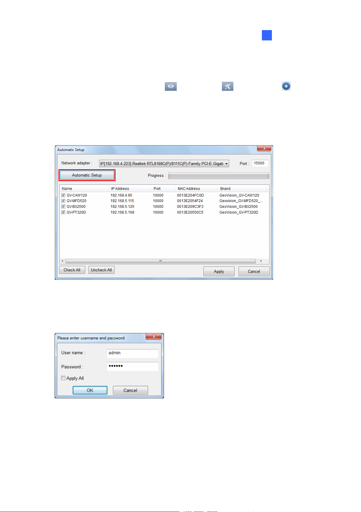
1.2.2 Adding Cameras
To add cameras to the GV-VMS, click Home , select Toolbar , click Configure and then
select Camera Install. When the camera list is empty, the Automatic Setup dialog box automatically
pops up.
1. Click Automatic Setup to search for IP cameras on the LAN.
Figure 1-6
2. The default login information for cameras is admin / admin. If the camera uses different ID and
password, double-click the camera to specify the login information and click OK. If you select
Apply Al l , the login information will be applied to all selected cameras.
Figure 1-7
3. Make sure the cameras you want to add are selected and click Apply. The cameras added are
now listed in the Camera List.
4. Close the dialog box by clicking X in the top-right corner. When adding camera for the first time,
the cameras will be automatically assigned to the live view grid.
13
Page 30
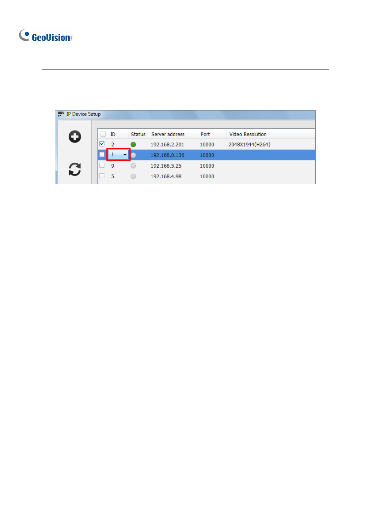
Tip: You can change the camera ID by clicking the ID of an inactive camera. The ID number does not
affect where the camera is positioned in the live view grid, but the cameras will be listed according to
the camera ID in setup pages such as Video Processing dialog box.
Figure 1-8
To add cameras using manual setup, camera scan or GV-IP Device Utility, refer to Adding IP Cameras
in Chapter 2.
14
Page 31

Configuring Main System
1
1.2.3 Accessing Live View
After adding cameras, you can access camera live view by dragging the camera in the Content List to
the live view grid.
1. Click Home
2. Click Camera in the content list to see the list of cameras added.
3. Drag the cameras to the live view grid.
, select Toolbar , and select Content List . The Content List appears.
Figure 1-9
For details on the live view, see Live View and Layouts in later in this chapter.
15
Page 32

1.2.4 Enabling the Recording
To start recording, click Home , select Toolbar , click Monitor and then select Start All
Monitoring. You can also individually select the cameras you want to start monitoring. By default,
every camera records with the following settings:
Default Recording Settings
Recording Mode Motion Detection
Resolution / Codec The camera’s current resolution / codec will be used.
When working with the system, you will undoubtedly want to change the settings as you go along.
z To change recording mode, see Record Settings later in this chapter.
z To change resolution and codec, see Configuring Video Setting in Chapter 2.
16
Page 33

Configuring Main System
1
1.2.5 Playing Back Video
Instant Playback
You can instantly play back the recorded video of a single camera from the camera live view. Place the
cursor on the live view, click the Instant Playback button, and select the time length: 10 seconds, 30
seconds, 1 minute or 5 minutes.
Figure 1-10
ViewLog
For more comprehensive playback functions, click ViewLog in the top-right corner.
1. Open the Content List by clicking Toolbar
2. Drag the camera you want to play back onto the playback screen from the Content List. The
colored areas in the timeline indicate that videos have been recorded during that time period.
and selecting Content List .
Figure 1-11
3. Select a camera in the grid, click on a colored area and click the Play button
or details on the ViewLog player, see Video Playback in Chapter 4. F
.
17
Page 34

1.3 Recording Settings
This section introduces the recording settings of the GV-VMS. To configure the recording setting of the
cameras, click Home
and click Record Setting. This dialog box appears.
, select Toolbar , select Configure , select System Configure,
Figure 1-12
By default, the system has the following recording settings.
Default Data Storage Settings
Recorded Files D:\Record\<camxx or audxx folder>. Storage Location
Event Database Files C:\CameraDBs\
Recycle Function Enabled with recycling threshold set to 32 G.
Recording Mode Motion Detection
Note: Once you change the camera ID of an inactive camera in the IP Device Setup page (Figure
1-8), the storage path’s folder will be created simultaneously. For example, camera of ID 1 will be
saved in the folder C:\Record\Cam01, camera of ID 02 will be saved in C:\Record\Cam02, and so on.
18
Page 35

Configuring Main System
1
1.3.1 Setting Global Recording Settings for All Cameras
In the top half of the Rec d Setting dialog box you can configure g ecording settings that will b
applied to all cameras, such as maximum length of e
to take upon recording errors.
or , lobal r e
ach video clip, recycling function and the actions
Figure 1-13
[Video Record]
Max Video Clip: Specifies the
maximum time length of each recorded file (from 1 to 5 minutes). If
you select 5 M minute eve e chopped into six 5-minute event files
Min, a 30-minute event will be chopped into thirty 1-minute event files. To decide what to set up
here, consider ho ou how frequent the activity is in your
surveillance area. backup process faster.
Post-Rec: Kee eriod of time after
ps on recording for a set p motion stops.
Pre-Rec: Records video for a set period of time before motion starts or an input device is triggered.
Specify the number of video clips to pre-record and specify the number of seconds per video clip.
For example, if you specify 3 video clips and 5 seconds, 15 seconds of video before each motion
or input event will be recorded. There will be a total of 3 video clips and each clip is 5 seconds
long.
in, a 30- nt will b ; if you select 1
w often you back up y r event files, and
Smaller file size makes
19
Page 36

To set the frame rate for pre-recording, you can select Urgent Event or General Event. The frame
rate for General Event and Urgent Event can be defined in the camera’s Record Setting dialog
(Figure 1-13). Normally, you would set a higher frame rate for Urgent Events (Ex: full frame) a
lower frame rate for General Events (Ex: key frame only).
Use Digital Watermark Protection: Click to watermark all recorded videos. Watermark is a way
to verify the authenticity of
modified in any way. For details, see Watermark Viewer in Chapter 9.
Recycle: When selected, the oldest recordings will be deleted when the system requires storage
space for new files. If it is not selected, the system will stop recording when disk space is full.
Select Register Event if you want to register event recycling to System Log.
Database Folder: The default storage path for Event Database (.db files) is at C:\CameraDBs\.
Click the … button
recordings is specified in the Storage option under the Record Type option.
Record Error Pro ces s: Click the Arrow button
recording error.
~ Invoke Alarm: Activates computer alarm by playing the selected sound file.
~ Invoke to Send Alerts: Sends e-mail notification. To see how to set up the e-mail server, refer
video streams, and to ensure that they have not been tampered with or
to specify a new storage path. Note that the storage path for the actual
to select what actions to take when there is a
box
nd a
to Setting Up Email Notification later in this chapter.
~ Register Event: Records the error to System Log.
~ Output Module: Triggers the selected output device. To see how to set up I/O devices, refer to
Chapter 6 I/O Applications.
20
Page 37

Configuring Main System
1
1.3.2
Setting Recording Settings for Individual Cameras
In th
e lower half of the Record Setting dialog box, you can select a camera and configure the recording
mod ly.
e and video storage location for the selected camera(s) on
Figure 1-14
1. Select the camera you want to configure. Hold the Shift key to select multiple cameras if needed.
2. Under Record Type, select Round-the-clock or Motion De
next to Storage to specify wher3. Click the Arrow button e to store the recorded videos. For
details, see Setting Up the Video Storage Location later in this section.
4. You can set different recording fra
Round-the-Clock mode, the camera will use the frame rate setting in 4a for non-motion events and
4b for motion events. For Motion Detection recording mode, the frame rate setting in 4b will be
used.
a. Define non-motion events as General or Urgent Event under Video Record Frame Rate.
b. For motion events, click the arrow button
as General or Urgent Event under Video Record Frame Rate.
The frame rate for General Event and Urgent Event can be defined in the camera’s General
Setting dialog box (Figure 2-13). Normally, you would set a higher frame rate for Urgent Events
(Ex: full frame) and a lower frame rate for General Events (Ex: key frame only).
Note:
me rates for motion and non-motion recordings. In
next to Record Type and define motion events
tect.
1. Refer to Configuring General Settings in Chapter 2 for setting the frame rate for General Event
and Urgent Event.
2. For details on other motion detection settings, refer to Setting Up Motion Detection later in this
section.
21
Page 38

1.3.3 Setting Up the Video Storage Location
You can create a maximum of 24 storage groups with different storage locations. The default storage
location is D:\Record\.
1. In the Record Setting dialog box, click the Arrow button
appears.
next to Storage. This dialog box
Figure 1-15
2. To add a new folder in the first storage group, click the Add button
folder. Only 1 folder can be assigned as storage folder per partition (e.g. only 1 folder in D drive).
. To add a new storage group, click the Add button
3
above t
4. Select Keep Days and specify the number of days to keep the video files in storage.
5. In the Enlarge Recyc
is the file size at which the recycling begins. The minimum and default recycle threshold is 32 GB
22
o assign at least one folder to the storage group.
le Threshold field, adjust the recycle threshold if needed. Recycle threshold
in the top-left corner and repeat the step
above Path and select a
.
Page 39

Configuring Main System
1
6. To specify the actions to take when hard disks become full, click the Arrow button next to Disk
Full Process.
Invoke Alarm: Activates computer alarm by playing the selected sound file.
Invoke to Send Al
erts: Sends e-mail notification. To see how to set up the e-mail server, refer
to Setting Up Email Notification later in this chapter.
Register Event: Records the error to System Log.
Outpu
t Module: Triggers the selected output device. To see how to set up I/O devices, refer
to Chapter 6 I/O Applications.
7. Click OK.
Note: If the designated storage space is not big enough to keep all video files for the defined days,
the Recycle Threshold setting will override the Keep Days setting.
23
Page 40

1.3.4 Setting
The motion detection settings will be applied to motion events in both Round-the-Clock mode and
Motion mode. The following features are available to prevent false motion detection:
z Object Size: Set a minimum and maximum object size to only detect objects within the size
range
z Sensitivity: Designate up to 10 levels of motion detection sensitivity for each outlined area
z Mask Region: Mask off unwanted areas for monitoring, such as cloud and tree movement
z Noise Tolerance: Ignore video noise when the lighting condition is poor or changed
z Ignore environmental changes: Ignore changes such as rain, snow and tree movement
Note:
1. You can only enable motion detection either by sensitivity or by object size at a time.
2. By default, the entire camera view is set to a motion sensitivity level of 9 with Noise Tolerance
and Process Video in Lower Resolution function enabled.
Up Motion Detection
24
Page 41

appears.
Configuring Main System
1
next to Record Type. This dialog box 1. In the Record Setting dialog box, click the Arrow button
Figure 1-16
2. You can refine motion detection by setting Object Size or Region Sensitivity.
Object Size: Limits motion detection to objects within a size range. Select User-defined.
Select Min. Object Size from the drop-down list and then drag an area on the image. Repeat
the process and set a Max. Object Size.
Set Region Sensitivity: Sets different detection sensitivities for different parts of the camera
image. Uncheck User-defined, adjust the sensitivity level by moving the slider, and then drag
an area on the image. You can create several areas with different sensitivity levels. You can
use the Add Mask
and Cut Mask buttons to create irregular shapes. By default,
the entire image is set to the sensitivity level 9.
3. To ignore motions in a certain area, click Mask Region, and then drag an area on the image. You
can use the Add Mask
and Cut Mask buttons to create irregular shapes.
25
Page 42

4. The following options are available to further reduce false alarm:
Noise
Ignore environmental changes: Ignores environmental changes such as rain or snow. When
Minimum Duration: Sets the minimum duration for which motions must persist for the system
5. You can reduce CPU loading by selecting Process Video in Lower Resolution. When enabled,
GV-VMS compresses live view into a lower resolution before GV-VMS detects if there is motion,
which reduces CPU loading, but may affect the accuracy.
6. To set the frame rate setting for motion events, click Video record frame rate and select Urgent
Event or General Event. Normally, you would set a higher frame rate for Urgent Events (Ex: full
frame) and select Urgent Event here for motion events. The frame rate for General Event and
Urgent Event can be defined in the camera’s General Setting page. See Configuring General
Setting in Chapter 2 for details.
Tolerance: Enable to ignore video noise and move the slider to adjust the level. The
higher the level, the more tolerant the system is to video noise. If the surveillance area is prone
to produce high noise possibly due to weather or light changes, set the level to High.
selected, objects moving steadily and repeatedly in the same direction for over 1.5 seconds
will be filtered out and ignored.
to issue a motion alarm. Specify the minimum duration in seconds (Max. 60 seconds).
7. Under Event Trigger, select the actions to take when motion is detected.
E-mail: Sends e-mail notification. To see how to set up the e-mail server, refer to Setting Up
Email Notification later in this chapter.
Output Module: Triggers the selected output de
to Chapter 6 I/O Applications.
Register Motion Event: Registers motion events to System Log.
Invoke Alarm: Activates computer alarm by playing the selected sound file.
8. Click OK to save your settings.
vice. To see how to set up I/O devices, refer
26
Page 43

Configuring Main System
1
1.4 Live View and Layouts
This section describes the functions on the camera live view and how to create new live view layouts
using the Content List. After adding cameras, you can access camera live view by dragging th
camera in the Content List to the live view grid. Refer to Accessing Live View earlier in this chapter for
details.
1.4.1
Utilizing Live View Functions
Live View Icons
Place the mouse cursor on the camera live view to see the icons
Figure 1-17
below.
e
Icons Functions
Instant Play
Snapshot
Tools
Plays back the video recorded in the last 10 seconds, 30 seconds, 1 minute, or 5
minutes.
Captures a snapshot of the current live view.
Includes the following options:
Monitor: Starts monitoring the camera.
Talk Back Toggle: Talks to the surveillance site from the PC. Only one
camera can be enabled at a time.
Properties:
Show Caption: Shows camera name on live view.
Keep Image Ratio: Locks aspect ratio of the camera image.
Close: Removes the camera from the layout grid.
27
Page 44

Tools
Zoom
Note: When PTZ Control is enabled on a PTZ camera, double-clicking the live view will make the
camera zoom in instead of switching to full screen.
The following options are available when related function is enabled or supported:
Set to Wave Out: Enables live view audio. (See Configuring Audio Setting,
Chapter 2)
PTZ Control: Enables PTZ functions. (See PTZ Camera later in this chapter)
Add to bookmark: Bookmarks a scene to watch later in ViewLog player. The
function is only available when the channel is recording.
Switches the live view to full screen. If th
clicking the Zoom button will replace the l
ere is a designated Zoom window,
ive view in the zoom window instead.
Functions on Live View and Content List
The live view screen can be controlled using the actions below.
Actions Functions
Mouse scroll Zooms in or out on the live view.
Double-click Displays the live view in full screen.
In the Content List (Home
the following options. Some options are only available when the related function is enabled or
supported.
Monitor: Starts monitoring the camera. (See Start Monitoring later in this section)
Video oc s: Opens the Video Processing dialog box. (S
Se ut: Enables live view audio. (Se
Talk Back T C. (See Configuring Audio Setting,
Focus V n a camera. (See Setting Focus View later
PTZ Setup:
Fisheye Se
Pr es ee Chapter 3 Video Analysis)
t to Wave O e Configuring Audio Setting, Chapter 2)
oggle: Talks to the surveillance site from the P
er 2)
Chapt
iew Setup: Creates up to 7 closed-up views i
section)
in this
Enables PTZ functions. (See PTZ Camera, Chapter 1)
ttings: Opens the Fisheye Settings dialog box. (See Fisheye View, Chapter 3)
>Toolbar > Content List ), right-click a camera to access
28
Page 45

Volume Indicator
Configuring Main System
1
You ca audio volume indicator on the top-left corner of the camera live view. Click the
Home bu
Show Volume
n display an
tton
Indicator.
, click the Toolbar button , click the Tools button , select Audio and selec
Figure 1-18
t
29
Page 46

1.4
.2 Arranging Live View Layouts
Follow the ste elow to create new live vie layouts.
1. In the Content List (Home
2. To add a layout, click the Add button
ps b w
>Toolbar > Content List ), click Layout.
Figure 1-19
and click Add Layout. This dialog box appears.
Figure 1-20
3. Name the new layout.
4. Select one of the three methods under Layout Setup and click OK.
Select an existing layout template.
Specify the number of live views in each row and column of the grid.
Customize your own layout.
30
Page 47

Configuring Main System
1
5. If you select Customize in the step above, the Customize Layout dialog box will appear.
r the grid if needed. a. Click the Reset button to specify a dimension fo
Figure 1-21
b. Select multiple squares and click the Merge button to create a larger square.
Figure 1-22
c. Click OK when you are done.
A message appears. Click Yes if you w
ant to automatically assign the cameras to the new layout.
Alternatively, you can click Camera in the content list and manually drag the cameras to the live view.
31
Page 48

Tip: You can right-click a layout in the Content List to access the following functio
ns.
Figure 1-23
32
Page 49

Configuring Main System
1
1.4
.3 Setting a Zoom Window
You can designate a Zoom Window to quickly see a close-up view of the camera image without
changing the rest of the live view layout.
Note:
1. Up to two Zoom Windows can be created on each live view layout.
2. When there are two Zoom Windows, GV-VMS will alternate between the first Zoom Window
and the second Zoom Window each time you click the Zoom button of a camera.
1. In the Content List (Home
Windows and drag Zoom Window to a live view grid.
>Toolbar > Content List ), select Layout, click
Figure 1-24
33
Page 50

Mov and click the Zoom button
he Zoom Window. corner. The camera live view is displayed in t
2. e the mouse cursor to a camera live view in the top-right
Figure 1-25
3. To remove the camera from the Zoom window, place the cursor on the live view, click the Tools
icon
again to close the Zoom Window.
and select Close. To change the live view grid back to a normal window, repeat this step
34
Page 51

Configuring Main System
1
1.4.4 Setting a Scan Window
You can assign multiple cameras to a Scan Window, and each camera will be shown in sequence for
the Scan Interval specified.
Note: Up to four Scan Windows can be created on each live view layout.
1. In the Content List (Home
Windows, and drag Scan Window to a live view grid.
2. Drag multiple cameras into the Scan Window.
>Toolbar > Content List ), select Layout, select
Figure 1-26
35
Page 52

3. Move the cursor to the Scan Window, click the Tools icon
, and select Properties. This dialog
box appears.
Figure 1-27
4. To adjust the order of a camera, select a camera and click the Up
5. To specify how many seconds to show the live view of each camera, click and adjust the Scan
Interval of each camera. In the figure above, each camera will be shown for 5 seconds. You can
click the Finger
6. To show camera name on live view, select Show Caption.
7. To lock the original aspect ratio of the camera image, select Keep Image Ratio.
8. Click OK.
button to apply this Scan Interval to all cameras.
and Down arrows.
36
Page 53

Configuring Main System
1
1.4.5 Setting Focus View
You can create up to 7 close-up views per camera and place these created close-up views inside live
view grid. This function is not supported for Fisheye Cameras and PTZ Cameras.
1. In the Content List (Home >Toolbar > Content List ), right-click a camera and
select Focus View Setup. A dialog box appears.
Figure 1-28
2. Click Enable and draw a box on the camera view to create a focus view. You can create multiple
focus views if needed.
3. You can click the Color drop-down list to change the color of the box if needed.
4. Click OK. The created focus views are listed under the came
ra.
5. You can now drag the focus views to live view grids.
Figure 1-29
37
Page 54

1.4.6 Automatic Switch am
You can have different (live view) layouts automatically switched at a specified interval.
1. Create and group several layout templates under the Content List (Figure 1-30
. Right-click the group to configure its Scan Setting to specify the scan interval (Figure 1-31).
2
ong Different Live View Layouts
).
Figure 1-30 Figure 1-31
To start the automatic switch, right-click the group and select Scan Start. In the example above,
Layout 1, Layout 2, and Layout 3 are autom ong each other every 10 seconds, with atically switched am
the currently displayed layout highlighted in orange.
38
Page 55

1
1.5 Start Monitoring
After setting up the following functions, it is important to start monitoring in order for the functions to
start working: Recording, Video Analysis, I/O, Motion Event Trigger and Schedule.
Configuring Main System
To start monitoring, click Home , click Toolbar , select Monitor , and select one of the
options:
Figure 1-32
Start Sched elect Start
Schedule Monitoring. The schedule takes precedence over the current settings, and these
ule Monitoring: If you want to start running a created schedule, s
functions will start and stop according to the schedule: Recording, Video Analysis, I/O, PTZ Auto
Functions, Motion Event Trigger and Network Conn
Start A ll Monitoring: Starts monitoring on all cameras to activate recording and video analysis
functions.
I/O Monitoring: Start I/O monitoring to activate I/O functions. I/O Monitoring is only available after
at least one I/O device is set up. You can select I/O Monitoring to enable I/O functions
independently without enabling recording and video analysis.
ections with Center V2 / Vital Sign Monitor.
39
Page 56

Camera#: Start monitoring the selected
cameras. You can also start monitoring individual
cameras by right-clicking the camera in
List ) and select Monitor.
Figure 1-33
the Content List (Home
>Toolbar > Content
Note: Moti detection and I/O trigger will only be registered in System Log if monitoring is started.
You will also need to enable Register Motion Event (Figure 1-16) and Register Input Event (Fig
6-7).
on
ure
40
Page 57

Configuring Main System
1
1.6 System
This section introduces system conf
Configuration
igurations of the GV-VMS.
1.6.1 Configuring General Setting
Let’s start with the options on the General Setting dialog box. Changes made in the General Setting
dialog box will be applied to the system. Click Home
select System Configure, and click General Setting. This dialog box appears.
, select Toolbar , select Configure ,
Figure 1-34
[L
ocation Name] The given name (maximum 14 characters) is displayed in main screen as the name
of the server.
[Monitor Option]
Start Delay: Start recording x second(s) after Start All Monitoring or Start I/O Monitoring is
selected.
Service Mode: Under Service Mode, GV-VMS can start automatically after system startup and
run in the background without logging into a Windows user account.
41
Page 58

[Display]
Enable DirectDraw Scale: Applies DirectDraw Scale t
supports it. For certain VGA cards, DirectDraw Scale can re
image problem and maintain DirectDraw Scale, change the image quality from High to Standard
[Video Setting] of the camera (Figure 2-4).
Note: The Enable Directdraw Scale function can gre enhance image q ity. Enable if your VG
card supports DirectX9. To check the version of your DirectX, click Start and run dxdiag. Open the
file and find the related information.
[Zoom Camera]
Auto enable wave out: Automatically enables Wave Out function of the camera in Zoom Window
or in full screen. Note that the Wave Out function needs to be enabled in the Audio Setting page of
the camera first.
Auto toggle talk back: Automatically enables Toggle Talk Back function of the camera in Zoom
Window or in full screen. Note that the Toggle Talk Back function needs to be enabled in the Audio
Setting page of the camera first.
o enhance image quality if your VGA card
sult in blurred images. To avoid the
atly ual A
Auto switch PTZ mapping: This function only applies to GV-Keyboards that are connected to
GV-VMS. When selected, PTZ control from the GV-Keyboard will be applied to the selected PTZ
camera. When not selected, the PTZ control buttons on GV-Keyboard will only be applied to t
first available PTZ camera.
[Exit Option]
Auto Resta
Auto Shut down Windows: Shuts down Windows OS after exiting GV-VMS.
rt Windows: Restarts Windows OS after exiting GV-VMS.
he
42
Page 59

1.6.2 Customizing Startup Settings
Configuring Main System
1
The Startup dialog box allows you to set the system to enable selected features at system startup. To
access the Startup settings, click Home
System Configure, and click Startup. This dialog box appears.
, select Toolbar , select Configure , select
Figure 1-35
[General]
Show Style: Change the color scheme of GV-VMS.
Auto Monitoring: Select one of the following monitor control modes at system startup:
~ Monitor All: Allows you to monitor all cameras and I/O (if available) at system startup.
~ Schedule Monitor: Allows you to start monitoring cameras by schedule. Refer to Schedule
later in this chapter.
~ I/O Monitor: Allows you to monitor all I/O devices.
~ Camera Monitor: Enables all cameras for monitoring.
Note: To manually start monitoring, click Home
one of the functions.
, click Toolbar , click Monitor and select
43
Page 60

Auto Run when Windows St art s: Automatically runs GV-VMS after Windows starts. If you did not
set an Auto Login account or an Auto Startup Login accou
startup asking for an account ID and password.
Startup and Hide into System Tray V-VMS appears in the system tray when aunch
Windows instead of displaying the system login window.
Note: Startup and Hide into System Tray and Auto Startup Login cannot function at the same
time. When both are enabled, Auto Startup Login will not be applied. For details on Auto Startup
Login, see Setting a Startup Auto Login User later in this chapter.
[Network]
WebCam Server: Automatically enables connection to WebCam Server at system startup.
Mobile Service: Automatically enables connection to Mobile Service at system startup. (For
applications such as GV-Eye mobile applications and GV-Edge Recording - Mac version)
: G you l
nt, the Login dialog box will appear at
Connect to Center V2: Automatically enables connection to Center V2 at system startup.
Connect to VSM: Automatically enables connection to Vital Sign Monitor Server at system
startup.
Control Center Server: Automatically enables connection to Control Center Server at system
startup.
anually enable the network connections listed above, click Home
and click Network
.
, click Toolbar Note: To m
44
Page 61

Configuring Main System
1
1.6.3 Customizing Display Position and Panel Resolution
You can customize the display settings of GV-VMS. C , select Toolbar ,lick Home select
Configure , select System Configure, and click Set Position. This dialog box appears. The r
side of the dialog box is only available when multiple monitors a
Figure 1-36
re installed.
ight
Select Monitor: If you have multiple monitors connected, select the monitor you want to configu
from the d
Position: Offsets the position of the GV-VMS window relative to the upper-left corner of the
screen. The default position is 0, 0. A position of 100, 60 will place the GV S window 100 p ls
to the right and p
GV-VMS window does not take up the entire screen.
Figure 1-37
Panel Resolution: Sets the Panel Resolution of the GV-VMS.
rop-down list.
-VM ixe
60 ixels below the upper-left corner. This function is only supported when the
re
45
Page 62

1.6.4 Setting Up Email Notification
When event ccur, you can receive alert notification through e-mails. Follow the steps below to
enable alert notification and set up the e-mail server.
The events that can trigger alert notification include: Video Lost, Recording Error, Disk Full, Motion
Detection, I/O Trigger, Scene Change, Intruder Event, Missing Object, Unattended Object, Scene
Change, Crowd Detection, Advanced Unattended Object, Advanced Scene Change Detection,
Advanced Missing Object and Face Detection.
1. Click Home
Send Alert s Approach Setup. This dialog box appears.
s o
, select Toolbar , select Configure , select System Configure, and click
46
Figure 1-38
Page 63

Configuring Main System
1
2. To enable e-mail notification, select Send Email and click Email Setup . This dialog box appears.
Figure 1-39
3. Set up the following fields (required):
SMTP Sever: Type your mail server’s URL address or IP address.
E-Mail From: Type the sender’s e-mail address.
E-Mail To: Type recipients’ e-mail addresses. For multiple recipients, add a semicolon
between each e-mail address.
Subject: Type a su mail alert.
bject for the e-
4. Click the Test Mail button to send a test e-mail and see whether the setup is correct. If the e-mail
fails to send, you may need to check the following settings:
SMTP Mail Server requires authentication: If the SMTP mail server needs authentication for
login, select this option and type your account name and password.
SMTP Server: Keep the default port 25 which is common for most SMTP servers. However
webmail providers such as Gmail, Yahoo, and Hotmail generally use different SMTP port. In
this case, check your e-mail provider for the SMTP port number. Select SSL if your e-mail
server requires the SSL authentication for connection.
47
Page 64

5. Complete other optional settings as needed:
Mail Content: Type the e-mail content that will be included in all e-mail notificaitons.
Attach Image Setup: Select Attach to include up to 6 snapshots in the e-mail. The image
format and size are selectable from drop-down lists.
Email-Alerts Interval: Specify the time interval (0-60 seconds) between e-mail alerts to
prevent e-mails from being sent too frequently. The default interval is 5 minutes, which means
that if motion lasts for more than 15 minutes, you will receive 3 e-mails at most. If motion lasts
for less than 5 minutes, you will receive one e-mail only.
Domain Name from DDNS: This option generates URL links for remote video playback in the
sent e-mails. For this function to work, enter the fixed IP address or domain name of the
GV-VMS, and enable WebCam Server.
E-mail in Text Mode: When WebCam Server is enabled, your e-mail alert will be sent in
HTML format. If you want to send the e-mail alert in pure text format, select this option.
Note: To enable WebCam Server, click Home
WebCam Server.
, click Toolbar , click Network and click
48
Page 65

1.6.5 System Idle Protection
Configuring Main System
1
When the computer is idle over a set period of time, the System Idle Protection can automatically log
out the administrator, and/or start monitoring.
1. Click Home
, select Toolbar , select Configure , select System Configure, and
select System Idle Protection Setting. This dialog box appears.
Figure 1-40
2. To automatically log out or switch to Startup Auto Login User, select Auto Logout or Switch to
Startup Login User if available, and then select the type of account to log out from the
drop-down list.
If you have set up a Startup Auto Login User, GV-VMS will switch to the Startup Login User instead
of logging out. The Startup Auto Login User is typically a user account with limited access rights.
For details, see Setting a Startup Auto Login User later in this chapter.
3. To automatically start monitoring, select Auto Monitoring, and use the drop-down list to select
Monitoring All, Schedule Monitoring, I/O Monitoring or Camera Monitoring. When Monitoring
All is selected, both I/O Monitoring and Camera Monitoring will be enabled.
Select Auto Network Service of Startup Setting to enable network connections selected in
Startup Setting (WebCam Server, CenterV2, Vital Sign Monitor, Control Center Server,
Backup Server (GV-Failover Server and GV-Redundant Server) and/or Backup Center). To
specify which network connections to enable at startup, see Customizing Startup Settings
earlier in this chapter.
4. In the System Idle Over field, type an idle time between 10 and 14400 seconds, after which the
settings configured in Step 2 or 3 will be applied.
49
Page 66

5. Click OK.
Note: The feature can monitor keystrokes or mouse clicks, even from IR Remote Control and
GV-Keyboard.
50
Page 67

Configuring Main System
1
1.6.6 Configuring Fast Key Lock
If you do not want to use certain fast keys to avoid interfering with keyboard use, you can disable the
fast key functions.
1. C
Fast Key Lock Setup. This dialog box appears.
, select Toolbar , select Configure ,lick Home select System Configure, and select
Figure 1-41
2. Select one of the four tabs: General, ViewLog, PTZ Control and Network.
3. Clear the checkmark for the fast keys you want to disable. To restore the fast keys, select the
checkbox again.
4. Click OK to apply your settings.
51
Page 68

1
.7 Account and Password
The password setup allows you to assign permission and rights to accounts. You can create up to
1,000 passwords. The s
c
onfigured for each account. Only Supervisor-level accounts are pre-set with access to the Password
Setup function. Click the account ID, click Password Setup, and select Local Account Edit. This
dialog box appears.
ystem will control access to functions based on the permission and rights
52
Figure 1-42
Page 69

1.7.1 Creating a New Account
To create a new account:
1. Click the New button at the lower-left hand corner. This dialog box appears.
Configuring Main System
1
Figure 1-43
2. Type the user’s ID name and password. Re-enter the same password in the Password
Confirmation field.
3. Give a Hint (optional) that would remind you of the password.
4. Select the account’s authorization level: Supervisor, PowerUser or User.
• Accounts belonging to the Supervisor level have permissions over all GV-Vital Sign Monitor
settings.
• By default, PowerUsers have the same permission and rights as Supervisors, except that
they cannot edit user information and delete the password system (described later).
• Accounts belonging to the User level are restricted from all system settings, and have only
limited access to certain functions.
5. Click OK to add the user.
6. If you want to enable the guest account, click Guest and clear the selection for Disable Account.
Guests are only allowed to watch live view.
After an account is created, only supervisors are allowed to edit the account in the future. To edit,
select an account from the account list. Or, right-click an account level (User, PowerUser, Supervisor),
and click Find Specific Account for a quick search. A valid password is required to edit a supervisor.
53
Page 70

1.7.2 Configuring Account Settin
You may find these options
Figure 1-44
Disable Account: Select if you want to disable this account.
to the right of the account list depending on the authorization level.
gs
Expire in xx day(s
days. The number you set will count down automatically. Specif
User cannot change password: The user is not allowed to change the set p
Force password change at next login: The user must change the password at next login.
Disable account
if user does not login after xx day (s): When the user does not log in the
system after a set number of days, its account will be disabled automatically.
Export this ID for IR Remote Control: Allows you to log into the system by using the
GV-Keyboard instead of using the general keyboard and mouse. For details see GV-Keyboard
User’s Manual.
Send password by Email:
click the […] button. For details on this feature, see Changing or Retrieving Password at Login
later in this chapter.
Login this ID automatically (Single User Mode): GV-VMS will automatically log into this account
after you click Login at startup.
): The account will expire and be disabled automatically after a set number of
y the number between 1 and 9999.
assword.
Allows you to retrieve passwords through e-mails. To specify e-mails,
54
Page 71

Configuring Main System
1
At the bottom of the page are global settings, which are applied to all accounts.
Figure 1-45
Allow removing password System: Enables the password removal utility. The option is critical if
you forget or is unable to retrieve any Supervisor password. With this option selected, you can run
the password removal utility PassUNINStall.exe from the GV folder and remove the password
database. Otherwise, you can only remove the password database by reinstalling Windows
operating system.
Enab e b as o W cted, after clic
l dou le p sw rd: hen sele king ViewLog, you will need to type the
passwords of any two supervisors to be able to continue. This option is only available when at
least two supervisor accounts have been created.
Make ID and passwords case-sensitive: Select to make account ID and passwords
case-sensitive.
Note:
1. Before running the utility PassUNINStall.exe, you need to disable Service Mode on GV-VM
(Figure 1-31) and then close GV-VMS. After running the utility, restart GV-VM
S to take effect.
2. The loss of passwords can be solved in the following two ways:
z Retrieving password through e-mails.
z Removi
account
ng password database by using the PassUNINStall.exe utility and rebuilding all
s.
However, if both Send Password by Email and Allow Removi ng Password System options are
not selected in advance, it is required to reinstall Windows operating system once you loss the
passwords.
S
55
Page 72

1.7.3 Changing or Retrieving Password at Login
When logging in GV-VMS, the Login dialog box allows you to change password or retrieve password
through e-mail.
Changing Password
1. In the Login d , click the Chan
appears.
2 e new password information, and click OK to save the changes. . Type th
ialog box ge Password button. The Change Password dialog box
Figure 1-46
Note: Only Supervisors can change the password.
Retrieving Password through E-mail
he password retrieval function works in the following ways after you click the Send Password butto
T n
n the Login dialog box.
i
If you are o
• ne of supervisors but do not remember your ID, separate passwords will be sent to all
supervisor e-mail accounts after you click the Send Password button.
• If you are one of the supervisors and remember your ID but forgot your password, enter your ID and
then click the Send Password button. The password will be sent to your e-mail account.
• If you are not a supervisor, enter your ID and then click the Send Password button. The e-mail with
your password will be sent to you.
56
Page 73

Configuring Main System
1
1.7.4 Preventing Unauthorized System Termination
The GV-VMS can be protected from stopping or restarting by an unauthorized account. To restrict an
account that does
steps below:
1. Click the account ID, clic
Setup dialog box appears.
2. Select a user
3. Select the VMS tab at the bottom, and clear the Exit System option to restrict the user from
quitting or restarting the system.
not belong to the Supervisor level from exiting or restarting the system, follow the
k Password Setup, and select Local Account Edit. The Password
from the user list to display its properties.
Figure 1-47
57
Page 74

1.7.5 Setting a Startup Auto Login User
The Startup Auto Login User is typically a user account with limited access rights. After system is
started, the GV-VMS will automatically log in with the Startup Auto Login User instead of showing the
Login dialog b
s
ystem settings.
1. Create an account you wan
this section for instructions.
2. Click the account ID, click Password Setup, and select Startup Auto Login. This dialog box
appears.
ox. The user can see that the system is on and working, but cannot tamper with the
t to use for Startup Auto Login. Refer to Creating an Account earlier in
Figure 1-48
3
. Select Startup Auto Login Setup.
4.
Type the ID and Password of the existing account you want to use.
5. Click OK.
If you have selected Auto Logout or Switch to Startup Login User if available in System Idle
Protection Setting dialog box (Figure 1-40), GV-VMS will switch to the Auto Startup Login account after
a period of system idle.
58
Page 75

1
.8 Schedule
Configuring Main System
1
You can create schedules to enable and disable the following functions at specific times of a day a
apply the schedule to a weekly plan, monthly plan or a specific date.
z Recording
z Alert upon
z PTZ object tracking
z PTZ Auto functions
z Video Processing
z I/O monitoring
z Network c
Click Home
dialog box appears.
motion detection
onnections to Center V2 and/or Vital Sign Monitor
, select Toolbar , select Configure , and then select Schedule Edit. This
nd
Figure 1-49
59
Page 76

1.8.1 Creating a S
The Setup Wizard is an easy way to create new schedule.
1. In the Schedule
2. Specify when to apply the sche
dialog box, click Schedule and select Setup Wizard. A dialog box appears.
chedule with Setup Wizard
dule plan and click Next.
Figure 1-50
Weekly: Applies the schedule plan to the selected days each week.
Special Day: Applies the schedule plan to a specific date each year.
Monthly: Applies the schedule plan to a specific day each month.
Note: You can apply the schedule plan to additional days or modify the time settings later. After the
schedule plan is created, refer to Step 3 in Creating a Schedule Manually later in this section.
3. Type a name for the schedule plan. If you have existing schedule plans, you can select Use
current plan and apply the selected pla ays. n to different d
60
Figure 1-51
Page 77

4. Click Next. This dialog box appears.
Figure 1-52
Configuring Main System
1
5. When the Include button
is selected, you will start with an empty timeline. Click the Add
button and drag across the timeline when you want the function to be enabled. Use the
Erase on butt when you want disable the function.
Figure 1-53
6. You can also click the Exclude button and start with everything disabled. The Add button
is now used for disabling the function instead and the Erase button is now used for
enabling the function.
7. Four categories are available on the left.
Camera:
~ Round-the-Clock Recording: When highlighting the timeline, you can choose to ap
ply
the frame rate settings for General Event or Urgent
Event. The settings here will
override the settings in Record Setting once schedule monitoring is started. For
information on General Event and Urgent Event, refer to Configuring General Setting,
Chapter 2.
~ Motion Detection Recording: When highlighting the timeline, you can apply different
motion sensitivity levels. If you select User Define, the sensitivity level selected in
Advanced Motion Detection Setup (Fig 1-16) will be used.
~ Alarm Trigger The Event Trigger methods selected in Advanced Motion Detection Setup
(Fig 1-16) will be triggere during the highlighted times.
d upon motion
61
Page 78

8. To apply the Camera and AVP schedules to selected cameras, use the camera drop-down list
~ PTZ: When highlighting the ti
that time. This option only appears when at least one PTZ camera is connected.
AVP: During the enabled times, the selected video processing functions will be enabled even
if the cameras are not recording.
I/O Monitoring: Enables I/O Monitoring.
Server: Enables network connections to Center V2 and/or Vital Sign Monitor.
meline, you can select a PTZ Auto function to enable during
above the timeline or click the Advanced Setting button
9. Click OK. The schedule plan created appears on the days you specified.
Figure 1-54
.
Tip:
1. You can drag the created plan on the left of the Schedule dialog box to the calendar on the right
and the plan will be apply to the date.
2.
To edit the schedule timeline, simply double-click the plan in the calendar.
62
Page 79

Configuring Main System
1
1.8.2 Cr
To manually create a schedule:
1. In the Schedule dialog box, click Plan and clic
Figure 1-55
2. Type a name for the plan and click OK.
3. Click Schedule and select an option below:
Edit Special Day: Applies the schedule plan to a specific date each year. Select a Date and a
eating a Schedule Manually
k Add. A dialog box appears.
Plan, and then click the Add button.
Edit Weekly: Applies the schedule plan to the selected days each week.
Edit Monthly: Applies the schedule plan to a specific date each month. Select a Day of the
month and a Plan, and then click the Add button.
4. Double-click the Plan to edit the schedu fer to Creating a Schedule with Setup
Wizard earlier in this section for details.
le timeline. Re
63
Page 80

1.8.3 Exporting and Importing Sched
You can export your current sche
n another computer.
o
To Export:
1. In the Schedule dialog box, click Schedule and click Export. A dialog box appears.
2. Specify the path to save the .xml file.
3. Click OK.
To Import:
. In the Schedule dialog box, click Schedule and click Import. A dialog box appears.
1
2. Specify where the exported .xml file is st
3. Click OK.
dule settings into an .xml file, and import it back later or to GV-VMS
ored.
ule Settings
64
Page 81

1
.9 System Log
Configuring Main System
1
System Log provides historical information that can help you track down events, system problems and
object counting data.
1.9.1 Setting System Log
In System Log Setting, you can specify whic
the system, and
, select Toolbar , select Configure , and then select System Log Setting. This dialog box
appears.
the number of days to keep the logs. To access System Log Setting, click ViewLog
h events to record, the interval time to write the event into
Figure 1-56
Select the types of event to register in System Log:
Monitor Event: Registers motion-triggered and I/O-triggered events. For this feature to work, you
must enable the Register Motion Event option in Figure 1-11 or the Register Input Event option
in Figure 6-7 in Chapter 6.
65
Page 82

General Event: Registers syst
Login/Logout Event: Registers the login/logout activities of local users to GV-VMS and WebCam
em startup/exit, network server start/stop, and monitoring
start/stop.
Server.
Counter Event:
Merge: Registers merging of recorded videos.
Backup: Registers backing up of recor
Delete: Registers deletion of recorded
CMS: Registers CMS related events.
Playback: Registers playback of recorded videos.
Notification: Reg ers email notifications
ist .
The following settings are available:
Interval of Motion Event: Specifies the log interval between motion-triggered events. This setting
could prevent the System Log from becoming too large in a motion-intensive surveillance area.
Interval of Input Event: Specifies the log interval between I/O-triggered events.
Always Keep Live Log: When selected, the current log will be displayed in system log. When not
selected, system log of the time selected in ViewLog timeline will be displayed if available.
Import Previous Days of Live Log Browser: Specifies how many days of data to be loaded into
the System Log.
Keep Days: Set the number of days to keep logs.
Registers counting results.
ded videos.
videos through remote connection.
Recycle: Enable the system to delete old log files to make space for new files when the space of
assigned Log Path is below 500 MB.
Log Path: Click the … button to specify a storage path. The default log path is :\GV folder\. The
available free space of the storage path will be displayed above.
Database Type: To choose how to save your system database, select Microsoft Office Access
Database or select Microsoft SQL Server and fill out the required fields
66
Page 83

Configuring Main System
1
1.9.2 Viewing System Log
To view the System Log, click ViewLog , select Toolbar , select Tools , and then select
ble, CMS Table, and Advanced. System Log. Three options are available: Monitor Ta
Monitor Table
Local events on GV-VMS are displayed.
Figure 1-57
[Monitor] Shows events related to camera connection and motion. Double-clicking an event will allow
you to view the related video (if available) in ViewLog.
[System] Shows system startup/exit, network server start/stop, and monitoring start/stop.
[Login] Shows whom and when has logged in and out of GV-VMS and WebCa
[Counter] Shows information and results of GV-VMS’s counter functions.
[M
erge] Shows merging event of recorded videos.
[
Backup] Shows backup event of recorded videos.
[Delete] Shows deletion of recorded videos through remote connection.
[Notification] Shows email notifications.
[I/O] Shows events related to I/O trigger.
[Playback] Shows playback of recorded videos.
m server.
67
Page 84

CMS Table
activities and service start related to CMS. CMS Table shows the connection status, login
Figure 1-58
Advanced Log Browser
To search for log data, click ViewLog , select Toolbar , select Tools , select System Log
and click Advanced to bring up the Advanced Log Browser. See Advanced Log Browser in Chapter 4.
68
Page 85

1
1.10 Other Functions
1.10.1 Setting Live View Pop-Up Video
The live view can pop up immediately whenever motion detection or input trigger occurs. To set up,
Configuring Main System
click Home
Camera Popup Setting. This dialog box appears.
, select Toolbar , select Configure , select System Configure, and click
Figure 1-59
Dwell Time: Specify the amount of time a pop-up live video to remain in the foreground.
Interrupt Interval: Specify the interval between live video pop-ups. This feature is useful when
several cameras are activated for a pop-up alert at the same time.
Camera Motion Invoke: Select the camera to enable auto pop-up upon motion detection. Note
that you need to start monitoring on the camera for this function to work.
Input Invoke: Select an input module using the drop-down list and select the input number using
the arrow buttons. Select Input Invoke and assign a camera to the input device. Whenever the
input is triggered, the live video of the assigned camera will pop up. Note that you need to start I/O
monitoring for this function to work.
Note: You can use the Mask Region function in the Advanced Motion Detection Setup dialog box
(Figure 1-16) to mask off certain areas of the camera image that you don’t want to detect motion.
69
Page 86

1.10.2 Adjusting to Dayligh
GV-VMS can automatically adjust to Daylight Saving Time (DST). If you are in a time zone that uses
DST, make sure DST is enabled. In Windows’ Control Panel, go to
Zone, and make sure Automatically adjust clock for Daylight Saving Time is selected.
Figure 1-60
In System Log, the DST events will be labeled with clock icons
t Saving Time
Date and Time, click Change Time
in the Time column.
Figure 1-61
In ViewLog, click the Camera Date Viewer and click the Search Event in DST button.
Figure 1-62
Note: Videos recorded during DST periods start with “GvDST”, e.g. GvDST20140722.avi, to
differentiate from regular video files that start with “Event”, e.g. Event20081022.avi.
70
Page 87

1
1.10.3 Setting Network Failure Detection
The Network Failure Detection function triggers an output device when the network connection
between GV-VMS and the specified network host has failed.
Configuring Main System
1. Click Home
2. Under IP Address, type the IP address or domain name of the remote host.
3. Next to Interval, type the time interval between each ping in minutes ranging from 1 to 999. If the
, select Toolbar , select Network , and click Network Failure Detection.
Figure 1-63
interval is 5 minutes, GV-VMS will ping the network
connection is still active.
4. Under Action, enable Output Module and select the output module and pin numbe
5. Click OK.
The selected output device will be triggered when the network host does not respond to GV-VMS’s
ping message.
host every 5 minutes to check if the
r.
71
Page 88

1
.11 PTZ Camera
With the PTZ control panel, you can control PTZ functions, e.g. pan, tilt, zoom, focus and preset po
After you have added a PTZ camera, follow the steps below to
1. Move the cursor to the camera live view and click the Tools button .
Figure 1-64
2. Click PTZ Control to enable PTZ function.
3. You can control GV-IP s using the following actions:
Speed Dome
enable PTZ functions.
ints.
Double-Click: The camera will center on the spot you clicked.
Drag: You can select Random Move or Center Move after right-clicking t
~ Random Move: Drag a line on the live view and the camera will move toward the
direction you dragged.
~ Center Move: Drag a box
dragged.
on the live view and the camera will zoom in on the area you
he live view.
72
Page 89

Configuring Main System
1
Control Panel and Auto Functions 1.11.1 Accessing PTZ
After PTZ Control is enabled, move the cursor to the live view to see the PTZ control panel. Note that
the PTZ control panel is hidden when live view resolution is less than 240 x 180.
Zoom In / Out
Home
Focus In / Out
Figure 1-65
In the PTZ control panel, click the Home button to access the advanced PTZ functions below. The
options available may differ depending on the model of your PTZ camera
Home: Returns the camera to Home position.
Iris Open / Close: Adjusts the camera iris. The iris Control buttons are only available for GV
Speed Dome.
Auto Focus: Adjusts the camera focus according to the subject.
Auto Iris: Adjusts th
e iris opening according to amount of light in the environment.
Auto Go: Allows you to enable Cruise, AutoPan, Sequence and Tour functions. You can click
Stop Auto Go to stop the Auto function you have enabled.
Auto Set: Allows you to set up AutoPan and Cruise functions. See the section below for details.
Preset Go: Moves the PTZ to a preset point by clicking the preset number.
.
-IP
Preset Set: Allows you to configure up to 256 PTZ preset points. Move the camera to the position
where you want set a preset point and then select a preset point number here.
To see how to set up the Sequence and Tour function, consult the manual of the connected PTZ
model.
73
Page 90

Auto Pan
The PTZ camera will continuously move between two horizontal positions. You can configure up to 8
sets of Auto Pan mode.
1. Move the camera to the start position of the AutoPan.
2. To mark the start position, click the Home button
and select Start AutoPan1.
3. Move the camera to the end position of the AutoPan. Any movement in the vertical direction will
not be included in the AutoPan.
4. To mark the end position, click the Home button
5. To create another Auto Pan mode, repeat the steps above using a different Auto Pan number.
To enable the AutoPan, click the Home button
created. To stop the AutoPan, simply click a Pan/T lt button in the PTZ Control Panel to interrupt the
Cruise
You can set up a route consisting of different direction
follow. Up to 4 Cruises can be created.
,
i
,AutoPan, or you can click the Home button select Auto Go, and select Stop Auto Go Function.
in the PTZ Control Panel, select Aut o Set,
, select Auto Set, and select End AutoPan1.
select Auto Go, and select the AutoPan number
s, angles, and zooms for the PTZ camera to
1. Move the camera to the start position of the Cruise.
2. To mark the start position, click the Home button in the PTZ Control Panel, select Auto Set,
and select Set Cruise 1.
3. Move the camera according to how you want the camera to m
positions, zooms, and speed of the movement will all be recorded for the Cruise. .
4. When you are finished with setting up the Cruise, click the Home button , select Auto S e t,
and select Set Cruise Stop.
5. To set up another Cruise route, repeat the steps above and select a different Cruis
To enable the Cruise route, click the Home button , select Auto Go, and select the Cruise num
created. T
the Cruise function, or you can click the Home button
Function.
74
o stop the Cruise route, simply click a Pan/Tilt button in the PTZ Control Panel to interrupt
, select Auto Go, and select Stop Auto Go
ove during the Cruise. The camera
e number.
ber
Page 91

Configuring Main System
1
1.1 tting PTZ Idle Protection and Advanced Functions
1.2 Se
In the Content List (Hom >Toolbar > Content List ), right-click the PTZ camera and
lect PTZ Setup. This dialog box appears. se
e
Figure 1-66
PT Speed: Adjusts the speed of pan and tilt movement.
Advanced: Click Setup to access advanced functions such as image attributes, sequence, tour
and Home position. Consult the manual of the conne
[Idle Protection]
When the PTZ camera remains stationary for a certain time, the PTZ can automatically move to a
Preset Point, enable an Auto function, begin a Multi Position Tour or start the PTZ sched
1. Click Enable.
2. Set the Idle Time. The PTZ c
time exceeds the specified Idle Time.
3
. Select Preset, Auto, Multi Position Tour or Schedule as protection mode. See Setting Multi
Position Tour below.
4. Click OK.
amera will follow the action selected in the next step after the idle
cted PTZ model for details.
ule.
75
Page 92

Setting Multi Position Tour
You can create a PTZ tour up to 64 pres ints. Note the number of preset points depends on
your PTZ capacity.
1. Select Multi Position Tour in the PTZ Configuration dialog box, and click the Setup button. This
dialog box appears.
with et po
Figure 1-67
2. S
elect a Preset as a start point.
3. Set the Dwell Time that the PTZ will remain in a preset p
4. Click Add and repeat Steps 2-3 to build more points in the tour.
oint.
76
Page 93

Chapter 2
IP Camera Setup .................................. 78
2.1 Adding IP Cameras ............................................................................ 78
2.1.1 Adding Cameras Manually.....................................................................................
2.1.2 Scanning Camera ..................................................................................................
2.1.3 Mapping GV-IP Cameras Using GV-IP Device Utility ............................................
2.2 Configuring Individual IP Cameras...............................................
2.2.1 Configuring Video Setting ...........................................................................
2.2.2 Configuring Audio Setting ...........................................................................
2.2.3 Configuring General Setting.......................................................................
2.3 Connection through RTSP, ONVIF & PSIA..................................
2.4 On Demand Display............................................................................
80
83
84
86
86
89
90
92
95
77
Page 94

IP Camera Setup
2.1 Adding IP Cameras
There are several ways to set up IP cameras in GV-VMS, and the setup procedures may vary
depending on the device.
CHAPTER
2
To access the IP Device Setup page, click Home
select Camera Install.
Figure 2-1
z To manually set up an IP camera, click Add Camera.
, select Toolbar , click Configure and
z To add an IP camera detected on the LAN, click Scan Camera.
z To add multiple IP cameras detected on the LAN, click Automatic Setup.
z To import IP cameras from the GV-IP Device Utility, click Import Camera.
z To map IP devices through the GV-IP Device Utility, click IP Device Utility.
78
Page 95

IP Camera Setup
2
For details on Automatic Setup, refer to Adding Cameras in Chapter 1. For other methods, refer to the
sections below.
Third-Party IP Devices
GV-VMS supports not only GeoVision’s own IP devices but also products from other leading
manufacturers. For the supported IP devices, refer to the Supported IP Camera List at
http://www.geovision.com.tw/english/4_21.asp
If the third-party camera is not detected using the scan in Scan Camera or Automatic Setup, you will
need to add the camera using Manual Setup. You may need to add the camera using RTSP, ONVIF or
PSIA protocols. Refer to Connection through RTSP, ONVIF & PSIA later in this chapter for details.
.
79
Page 96

2.1.1 Adding Cameras Manually
To manually add IP cameras, follow the steps below.
1. Click Add Camera
Figure 2-2
2. Type the IP address, username and password of the IP camera. Modify the default HTTP port 80 if
. This dialog box appears.
necessary.
3. Select a camera brand and model name from the Brand and Device drop-down lists respectively.
This dialog box appears.
Figure 2-3
80
Page 97

2
4. In the dialog box, configure the options which may vary depending on camera brands.
Dual Streams: GV-IP Cameras are set to dual streams by default. Select this option to apply
the dual-streaming settings (lower resolution for live view and higher resolution for recording) if
the camera supports dual streams.
Query: Detect and apply the current codec and resolution setting on the camera. This function
may not be available for some third-party cameras.
Camera list: Select a camera number.
Port: Modify the video streaming port number if necessary.
Stream Type: You may have the option of Single Stream or Dual Streams depending on
camera models.
Codec Type: You may have different codec options depending on camera models. If the
selected camera supports dual streaming, the live view codec and recording codec can be set
differently.
IP Camera Setup
Resolution: You may select the different resolutions for live view and recording.
5. Click Apply to add the IP camera to the IP Device List.
6. To connect the added camera, click the box besides the ID column. Upon successful connection,
the Status icon shows green, with the video resolution and bit rate being displayed in the
correspondent columns.
Figure 2-4
7. To change the number of the camera, click the camera’s ID and select a desired number. Note this
function is only available for the disconnected cameras.
81
Page 98

Note: The indication of status icons is as below.
Connected
Connecting
Connection Failed
Inactive Camera
Started Monitoring
Pre-Rec Enabled
Tips: You can access the configuration interface of the connected IP camera by right-clicking the IP
camera and selecting Remote Camera Setting.
The camera is connected.
GV-VMS is trying to connect to the camera.
Unable to connect to the camera. Place the cursor on the red icon to
see the error message.
The camera is inactive. Select the checkbox to connect to the
camera.
The camera is under monitoring.
Pre-recording is enabled.
82
Page 99

2.1.2 Scanning Camera
You can add camera by scanning the cameras in the LAN.
IP Camera Setup
2
1. Click Scan Camera
2. In the Scan Camera dialog box, click Start Scan. The IP devices detected are displayed.
.
Figure 2-5
3. Double-click the IP device you wish to connect. This dialog box appears.
Figure 2-6
4. Type the username and password of the IP device and click OK. Figure 2-3 appears.
5. Click Apply. The IP camera is added to the IP Device List and automatically enabled for
connection (Figure 2-1).
83
Page 100

2.1.3 Ma ppi ng GV-IP Cameras Using GV-IP Device Utility
The GV-IP Device Utility detects all available GV-IP Devices on the same LAN and allows you to map
detected cameras to channels. You can then export the device list and import it to another GV-VMS.
This method is useful when you want to connect to the same cameras from multiple GV-VMS. The
GV-IP Device Utility also allows you to quickly set the IP address, upgrade firmware, export/import
device settings and reboot the device.
To set up multiple GV-IP Cameras using GV-IP Device Utility:
1. Click IP Device Utility
the window.
Figure 2-7
2. To map the desired IP camera to a channel, drag the IP camera from the Camera List to the
. All the available IP cameras on the LAN are detected and listed in
desired channel number in the Dispatch Pattern section.
3. By default, the login username and password for the IP camera both are set as admin. If the
added IP camera does not use the default settings, you need to right-click the IP camera in the
Dispatch Pattern section and select Login User Information to modify its login information.
4. To map more IP cameras, repeat steps 2 and 3.
84
 Loading...