

Page 1
GV-VD8700 IR Vandal Proof IP Dome
User’s Manual V1.00
Before attempting to connect or operate this product,
please read these instructions carefully and save this manual for future use.
VD8700V10-UM-A
Page 2

© 2018 GeoVision, Inc. All rights reserved.
Under the copyright laws, this manual may not be copied, in whole or in part,
without the written consent of GeoVision.
Every effort has been made to ensure that the information in this manual is
accurate. GeoVision, Inc. makes no expressed or implied warranty of any kind
and assumes no responsibility for errors or omissions. No liability is assumed
for incidental or consequential damages arising from the use of the information
or products contained herein. Features and specifications are subject to
change without notice.
Note: No memory card slot or local storage function for Argentina.
GeoVision,
9F, No. 246, Sec. 1, Neihu Rd.,
Neihu District, Taipei, Taiwan
Tel: +886-2-8797-8377
Fax: +886-2-8797-8335
http://www.geovision.com.tw
Trademarks
series products are trademarks of GeoVision, Inc. Windows is the registered
trademark of Microsoft Corporation.
March, 2018
Inc.
used in this manual: GeoVision, the GeoVision logo and GV
Page 3

Preface
Welcome to the GV-VD8700 IR Vandal Proof IP Dome User’s Manual. The instructions will
guide you through the installation and use of the camera.
This Manual is designed for the following models and firmware version:
Model Model Number Firmware Version
IR Vandal Proof IP Dome GV-VD8700 V1.00
i
Page 4

Contents
Contents.................................................................................................................... ii
Note for Connecting to GV-DVR / NVR / VMS.........................................................vi
Note for Recording ..................................................................................................vii
Note for Installing Camera Outdoor ......................................................................viii
Optional Accessories.............................................................................................. ix
Chapter 1 Introduction........................................................................................... 1
1.1 System Requirements.............................................................................................3
1.2 Packing List ............................................................................................................4
1.3 Overview.................................................................................................................6
1.4 Installing the Camera ..............................................................................................9
1.5 Connecting the Camera........................................................................................ 19
1.6 I/O Connector .......................................................................................................20
Chapter 2 Getting Started.................................................................................... 21
2.1 Looking Up the IP Address....................................................................................21
2.2 Changing the static IP Address .............................................................................22
2.3 Accessing Your Surveillance Images ....................................................................24
2.3 Configuring the Basics ..........................................................................................26
Chapter 3 Accessing the Live View .................................................................... 27
3.1 The Live View Window..........................................................................................27
3.2 The Control Panel of the Live View Window..........................................................29
3.3 Snapshot of a Live Video ......................................................................................31
3.4 Video Recording ................................................................................................... 31
3.5 Picture-in-Picture View..........................................................................................32
Chapter 4 Administrator Mode............................................................................ 33
4.1 Audio & Video Settings .........................................................................................34
4.1.1 Video Settings........................................................................................... 34
4.1.2 Audio Settings........................................................................................... 36
4.1.3 RTSP ........................................................................................................37
4.1.4 Privacy Mask............................................................................................. 38
4.1.5 Text Overlay ..............................................................................................39
ii
Page 5

4.2 Event and Alerts....................................................................................................40
4.2.1 Face Recognition ...................................................................................... 40
4.2.2 Tampering Alarm ....................................................................................... 41
4.2.3 Motion Detection .......................................................................................42
4.2.4 I/O Control ................................................................................................43
4.2.4.1 Input Settings..............................................................................43
4.2.4.2 Output Settings........................................................................... 44
4.2.5 E-mail........................................................................................................ 45
4.3 Network ................................................................................................................ 46
4.3.1 LAN Configuration..................................................................................... 46
4.3.2 Advanced TCP/IP......................................................................................48
4.3.3 IP Filter ..................................................................................................... 51
4.4 Management......................................................................................................... 52
4.4.1 Date and Time...........................................................................................52
4.4.2 User Account.............................................................................................53
4.4.3 Tools .........................................................................................................54
4.4.4 External Storage Settings.......................................................................... 56
4.4.5 System Log ...............................................................................................57
Chapter 5 Face Recognition................................................................................ 58
5.1 Features ............................................................................................................... 59
5.2 Installation Flowchart ............................................................................................ 60
5.3 Ideal Camera Position...........................................................................................61
5.4 Adjusting Illumination............................................................................................ 63
5.4.1 Daytime..................................................................................................... 63
5.4.2 Nighttime................................................................................................... 64
5.4.3 Low Illumination (WDR).............................................................................65
5.5 Enrolling Face Data .............................................................................................. 66
5.5.1 Photo Requirements ................................................................................. 69
5.6 Face Recognition Basic Settings...........................................................................72
5.6.1 Settings..................................................................................................... 72
5.6.2 License .....................................................................................................73
5.6.3 Management............................................................................................. 74
5.6.4 Events....................................................................................................... 75
Chapter 6 Recording and Playback.................................................................... 78
6.1 Playback Using the Memory Card......................................................................... 78
iii
Page 6

Chapter 7 Advanced Applications ...................................................................... 79
7.1 Upgrading System Firmware.................................................................................79
7.1.1 Using the Web Interface............................................................................ 79
7.1.2 Using the GV-IP Device Utility ................................................................... 80
7.2 Restoring to Factory Default Settings.................................................................... 82
7.2.1 Using the Web Interface............................................................................ 82
7.2.2 Directly on the Camera .............................................................................82
Chapter 8 DVR / NVR / VMS Configurations ...................................................... 83
8.1 Setting Up IP Cameras on GV-DVR / NVR............................................................ 84
8.1.1 Customizing Camera Settings on GV-DVR / NVR .....................................86
8.2 Setting Up IP Cameras on GV-VMS......................................................................88
Chapter 9 Smart Device Connection .................................................................. 91
Appendix ................................................................................................................. 92
A. RTSP Protocol Support ............................................................................................. 92
B. Limitations to Face Recognition ................................................................................93
iv
Page 7

Regulatory Notices
FCC Notice
This equipment has been tested and found to comply with the limits for a Class A digital
device, pursuant to part 15 of the FCC Rules. These limits are designed to provide reasonable
protection against harmful interference when the equipment is operated in a commercial
environment.
Class A
This equipment generates, uses, and can radiate radio frequency energy and, if not installed
and used in accordance with the instruction manual, may cause harmful interference to radio
communications. Operation of this equipment in a residential area is likely to cause harmful
interference in which case the user will be required to correct the interference at their own
expense.
CE Notice
This is a Class A product. In a domestic environment, this product may cause radio
interference in which case the user may be required to take adequate measures.
RoHS Compliance
The Restriction of Hazardous Substances (RoHS) Directive is to forbid the use of hazardous
materials of production. To meet the RoHS Directive requirements, this product is made to be
RoHS compliant.
v
Page 8

Naming Definition
GV-DVR / NVR
GV-VMS
GeoVision Analog and Digital Video Recording Software. The
GV-DVR also refers to GV-Multicam System or GV-Hybrid DVR.
GeoVision Video Management System for IP cameras.
Note for Connecting to GV-DVR / NVR / VMS
The camera is designed to work with and record on GV-DVR / NVR / VMS, a video
management system.
Once the camera is connected to the GV-DVR / NVR / VMS, the resolution set on the
GV-DVR / NVR / VMS will override the resolution set on the camera’s Web interface. You can
only change the resolution settings through the Web interface when the connection to the
GV-DVR / NVR / VMS is interrupted.
vi
Page 9

Note for Recording
1. By default, the recording function is disabled. Configure the function in the camera’s Web
interface to record alarm events to the memory card inserted in the camera upon
disconnection from GV-DVR / NVR / VMS. See 4.4.3 Tools for details.
2. Mind the following when using a memory card for recording:
Recorded data on the memory card can be damaged or lost if the data are accessed
while the camera is under physical shock, power interruption, memory card
detachment or when the memory card reaches the end of its lifespan. No guarantee is
provided for such causes.
The stored data can be lost if the memory card is not accessed for a long period of
time. Back up your data periodically if you seldom access the memory card.
Memory cards are expendable and their durability varies according to the conditions of
the installed site and how they are used. Back up your data regularly and replace the
memory card annually.
Replace the memory card when its read/write speed is lower than 6 MB/s or when the
memory card is frequently undetected by the camera.
To avoid power outage, it is highly recommended to apply a battery backup (UPS).
3. For better performance, it is highly recommended to use memory cards of the following
specifications:
Micro SD card of MLC NAND flash, Class 10.
vii
Page 10
Note for Installing Camera Outdoor
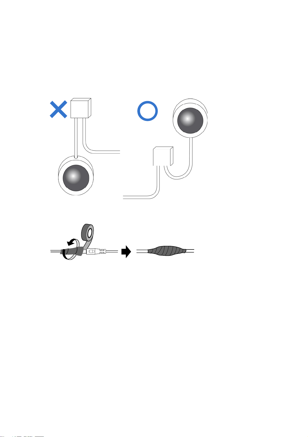
When installing the camera, be sure that:
1. The camera is set up above the junction box to prevent water from entering the camera
along the cables.
2. Any PoE, power, audio and I/O cables are waterproofed using waterproof silicon rubber
or the like.
3. The screws are tightened and the cover is in place after opening the camera cover.
viii
Page 11

Optional Accessories
Optional devices can expand your camera’s capabilities and versatility. Contact our sales
representatives for more information.
Device Description
GV-Mount Accessories provide a comprehensive lineup of
GV-Mount Accessories
GV-PA191 PoE Adapter
GV-PoE Switch
GV-Relay V2
Metal PG21
Conduit Connector
accessories for installing the camera on ceiling, wall corner
and pole. For details, see GV-Mount Accessories
Installation Guide.
The GV-PA901 is a Power over Ethernet (PoE) adapter
designed to provide power to the IP device through a single
Ethernet cable.
GV-PoE Switch is designed to provide power along with
network connection for IP devices. GV-PoE Switch is
available in various models with different numbers and
types of ports.
GV-Relay V2 is designed to expand the voltage load of GV
IP devices. It provides 4 relay outputs, and each can be set
as normally open (NO) or normally closed (NC)
independently as per your requirement.
The metal PG21 conduit connector is used for running the
wires through a 3/4” conduit pipe.
Power Adapter
Contact our sales representatives for the countries and
areas supported.
ix
Page 12
Chapter 1 Introduction
GV-VD8700 Vandal Proof IP Dome camera features cutting-edge face recognition technology
that allows users to identify important personnel from its database, on the fly. Up to 10,000 face
profiles can be defined in the camera’s database, and also categorized to meet various
corporate needs, such as facilitating customer service or security management and more. The
camera’s face recognition mechanism is effective for a distance of up to 4 m (13.12 ft) while
able to identify up to 10 persons simultaneously. With a recognition time of within 2 seconds, it
can quickly identify VIP guests and / or potential intruders. When integrated with GV-VMS,
GV-VD8700’s face recognition can be used to trigger alerts according to the predefined rules,
thereby providing an improved, reliable security management.
As an outdoor camera, GV-VD8700 is designed with IK10 vandal resistance and IP66 ingress
protection. The camera can support H.265 video codec to achieve better compression ratio
while maintaining high-quality pictures at reduced network bandwidths. For night operations,
the camera is equipped with an IR effective distance of up to 40 m (131.23 ft). Its WDR and
Backlight Compensation allow the camera to detect faces in environments with drastic light
contrast.
1
Page 13

Features:
1/2.5” progressive scan low lux CMOS
Min. illumination at 0.04 lux
Triple streams from H.265 and H.264
Up to 30 fps at 3840 x 2160
Vandal resistance (IK10)
Ingress protection (IP66)
Megapixel varifocal lens
P-iris lens for auto iris control
Day and Night function (with removable IR-cut filter)
Intelligent IR
Introduction
1
Wide Dynamic Range (WDR)
IR distance of up to 40 m (131.23 ft)
3-axis mechanism (pan / tilt / rotate)
One sensor input and digital output
Built-in micro SD card slot (SD/SDHC/SDXC/UHS-I, Class 10) for local storage
DC 12V / PoE (IEEE 802.3af)
One-way audio
Defog
Motion detection
Tampering alarm
Face recognition
Text overlay
Privacy mask
IP address filtering
Recording assigned by GV-Edge Recording Manager (Windows & Mac)
Supports iPhone, iPad, and Android
3 languages on Web interface
ONVIF (Profile S) conformant
2
Page 14

1.1 System Requirements
Access the GV-VD8700 through Microsoft Internet Explorer 11 or later. Make sure the
connected network is stable throughout the application.
3
Page 15
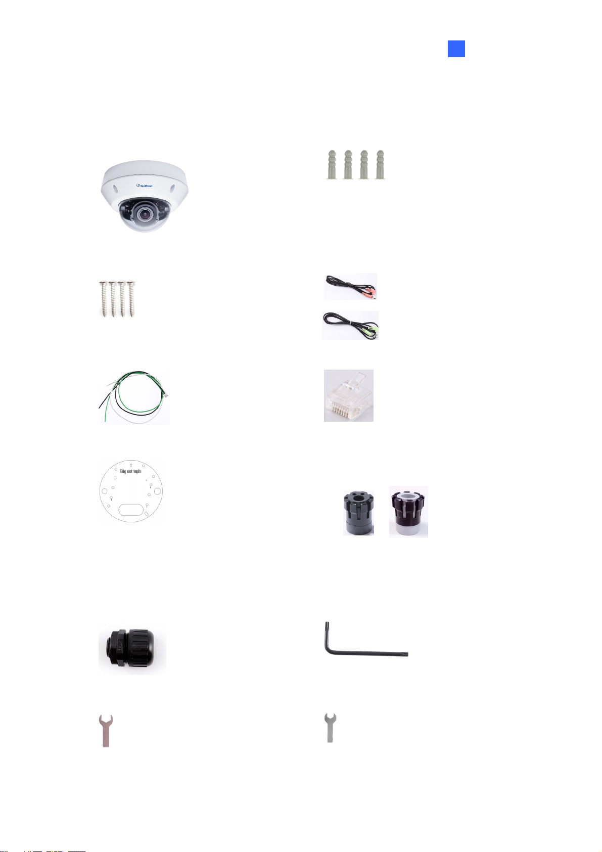
1.2 Packing List
Introduction
1
H.265 Vandal Proof Dome
Screw x 4
I/O Cable
Screw Anchor x 4
Audio Wire x 2
RJ-45 Connector
Installation Sticker
PG21 Conduit Connector
Big Concave Hexagon Wrench
Waterproof Rubber Sets (for RJ-45
Cat.5 and DC12V / for RJ-45 Cat. 6)
Cat.5
(Ø 5 mm)
Cat.6
(Ø 6 mm)
Torx Wrench
Small Concave Hexagon Wrench
Silica Gel Bag Sticker (for Silica Gel Bag)
4
Page 16
Conduit Converter
Ruler
8 GB Micro SD card
(MLC, SDHC, Class 10)
(The Micro SD Card is preinstalled in
the camera)
Download Guide
Warranty Card
Note: You can run the wires through a conduit pipe. After you have threaded all the wires,
install the supplied conduit converter and plastic PG21 conduit connector with a
self-prepared 1/2’’ conduit pipe to the camera. Power will have to be supplied through a PoE
adapter, because the power adapter wire does not fit in a 1/2” pipe. You will have to purchase
your own PG21 conduit connector if you want to use a 3/4” or 1” pipe.
Plastic PG21
conduit connector
Conduit pipe
Conduit converter
A metal PG21 conduit connector can be purchased upon request. The metal PG21 conduit
connector can be connected with a 3/4” pipe.
Conduit converter
Metal PG21
conduit connector
Conduit pipe
5
Page 17
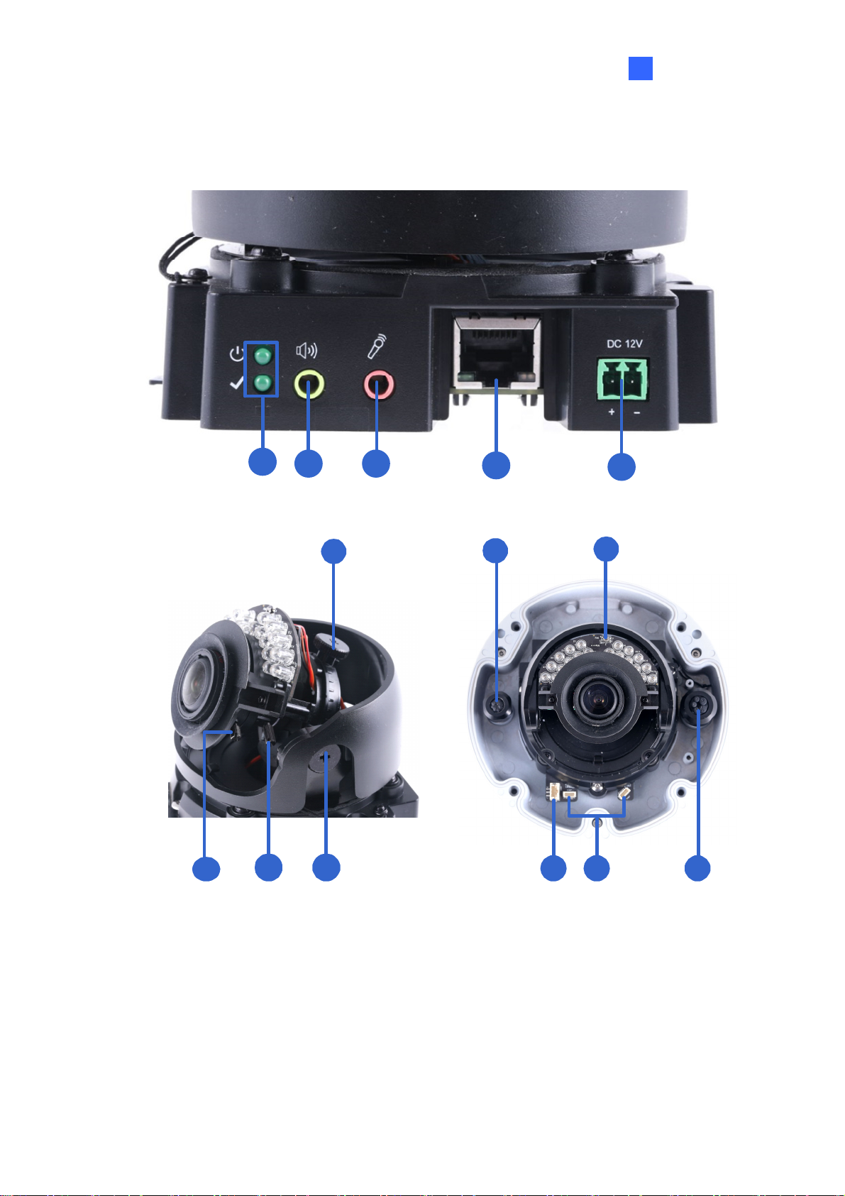
1.3 Overview
Introduction
1
1
9
10 11
2 3
6
Figure 1-1
4
7
12
13
5
8
14
6
Page 18
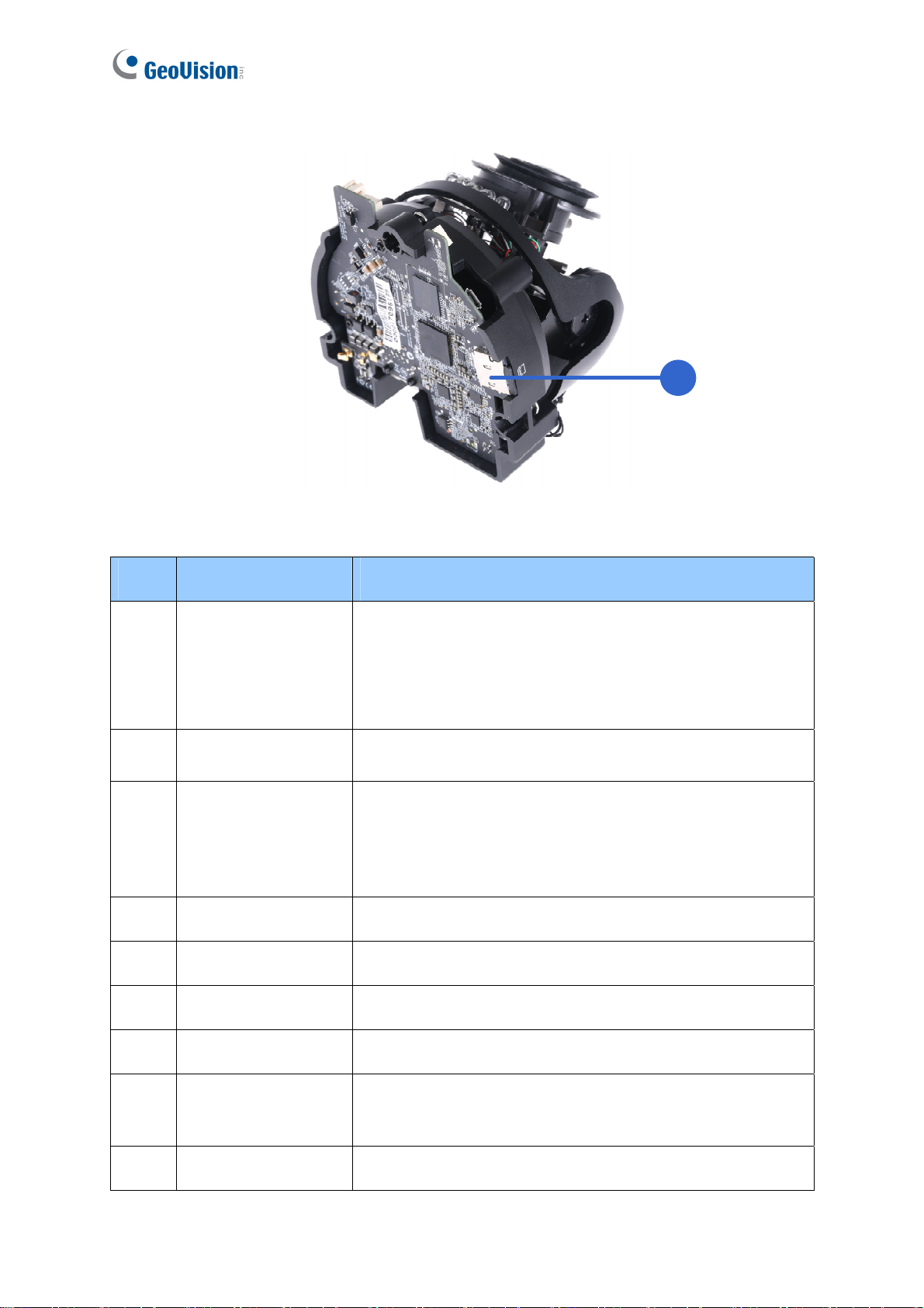
15
Figure 1-2
No. Name Description
The power LED (top) turns on when the power is on and
1 LED Indicators
2 Audio Out
3 Line In
4 LAN / PoE Connects to a 10/100 Ethernet or PoE.
5 DC 12V Connects to power.
turns off when there is no power supply. The status LED
(bottom) turns on when the system operates normally and
turns off when an error occurs.
Currently not functional.
Connects to a microphone for audio input.
Note: This interface only works with an external
microphone with power supply.
6 Rotational Screw Loosens to rotate the camera.
7 Conduit Connector Waterproofs the Ethernet cable.
8 Default Button
9 Focus Screw Adjusts the focus of the camera.
7
Resets the camera to factory default settings. For details,
see 7.2 Restoring to Factory Default Settings.
Page 19

10 Zoom Screw Zoom the camera in or out.
11 Tilt Screw Loosens the screw to tilt the camera.
Introduction
1
12 I/O Connector
Connects to I/O devices. For details, see 1.6 I/O
Connectors.
Built-in Microphone
Connects to a built-in microphone to record sound. For
13
Connectors
details, see 1.5 Connecting the Camera.
14 Conduit Connector Waterproofs the audio / I/O wires.
Inserts a micro-SD card (SD/SDHC/SDXC/UHSI, Class
15 Memory Card Slot
10) to store recording data.
8
Page 20
1.4 Installing the Camera
The camera is designed for outdoors. With the standard package, you can install the camera
on the ceiling.
Note:
1. For optimal face recognition results, follow recommended guidelines to install the
camera. For details, see 5.3 Ideal Camera Position.
2. You can also install the camera to ceilings, wall corners (concave or convex), and poles
using optional mounting kits. For details on these installations, see GV-Mount
Accessories Installation Guide.
3. You need to format the memory card before using it for the first time. For details, see
4.4.4 External Storage Settings.
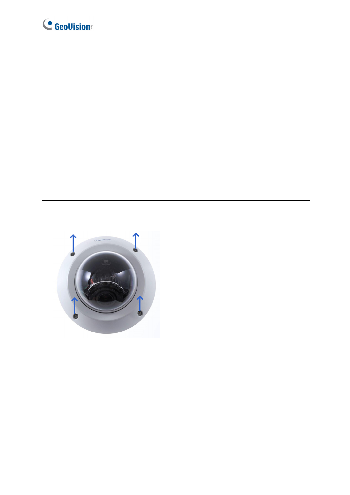
1. Remove the housing cover with the supplied torx wrench.
9
Figure 1-3
Page 21
Introduction
1
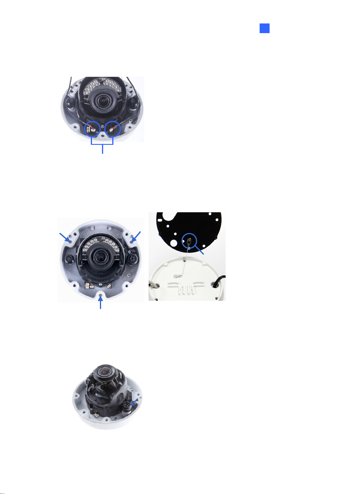
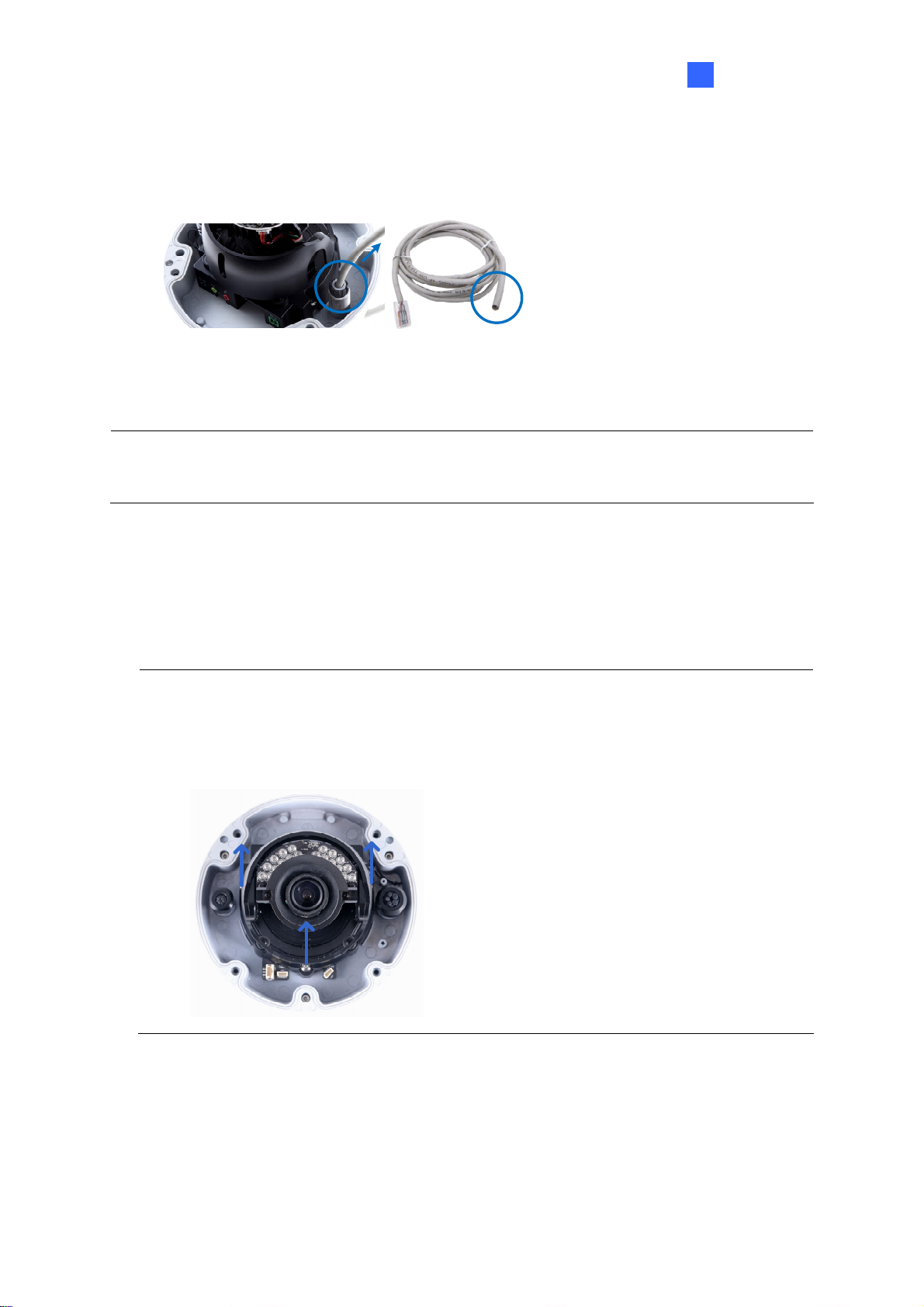
2. Optionally remove the cables that attach the built-in microphone to the camera to assist
with installation.
Cables for built-in microphone
Figure 1-4
3. Remove the back plate with the supplied torx wrench and remove the safety lock with a
Philips screwdriver. Keep the removed screw for later use.
Safety lock
Figure 1-5
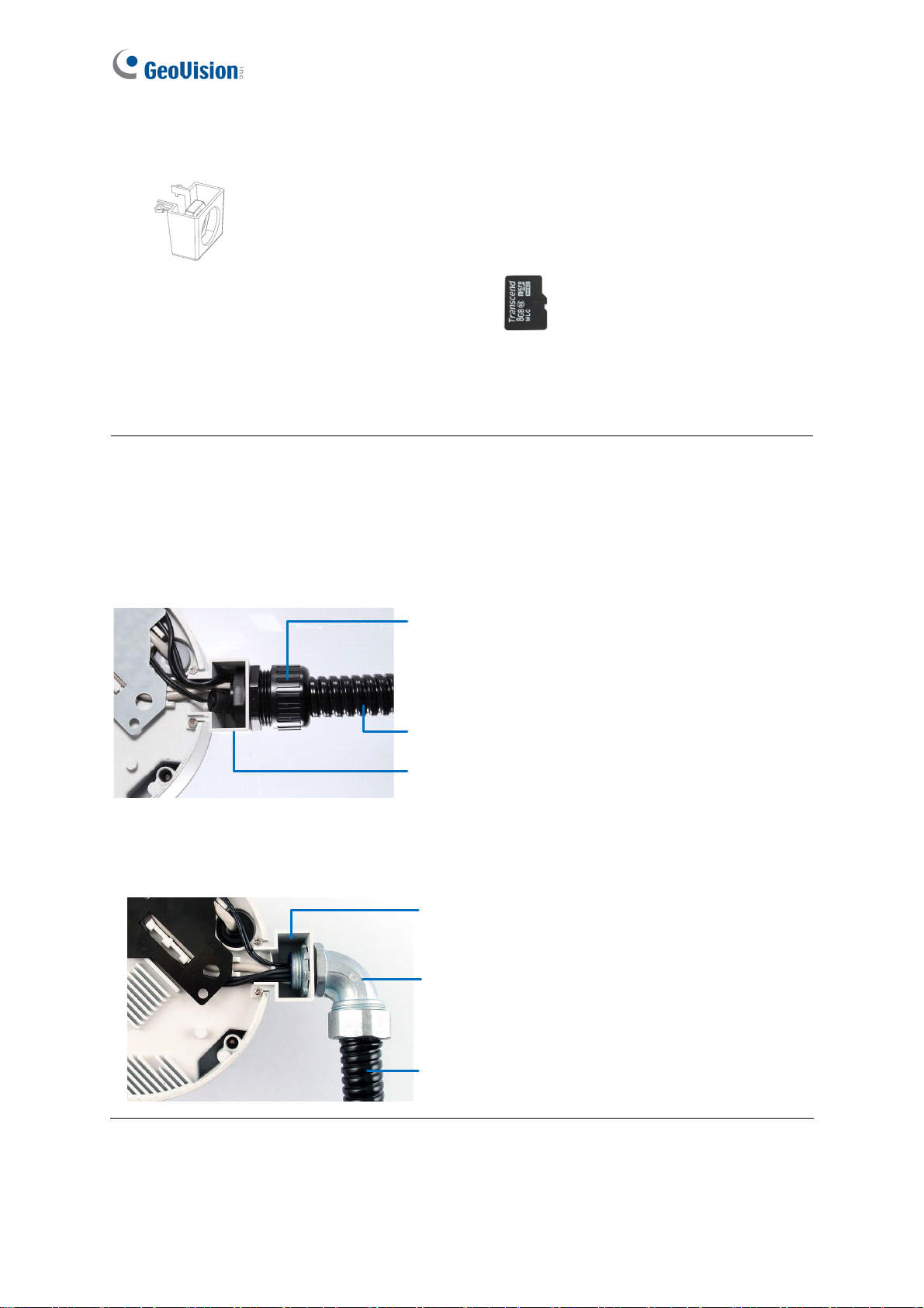
4. Thread wires into the camera.
A. Rotate to remove the cap of the conduit connector.
Figure 1-6
10
Page 22
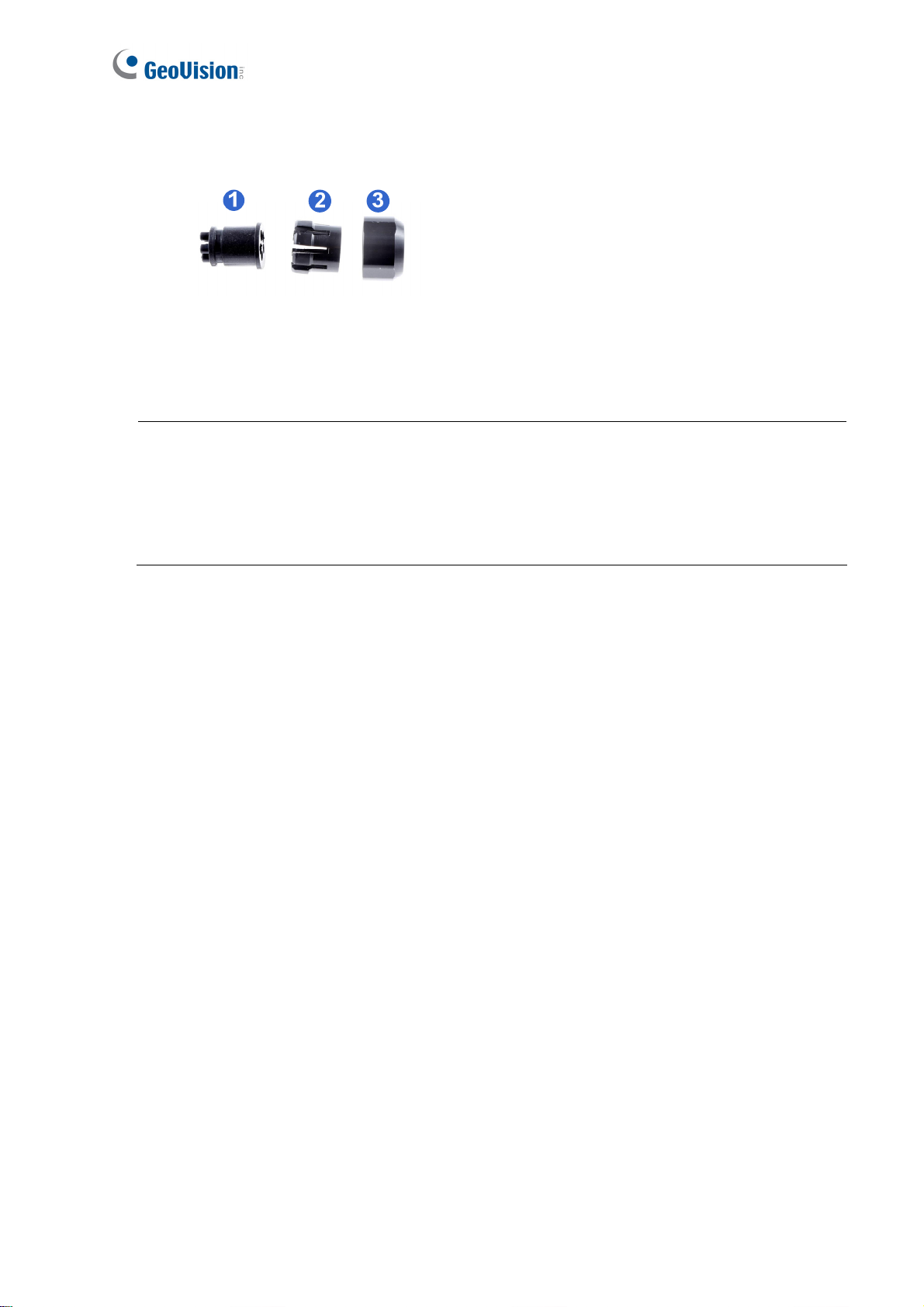
B. Unplug the conduit connector inside the housing and disintegrate the connector. You
should have 3 parts:
Figure 1-7
C. Thread the audio wires and I/O wires through the conduit entry and then through
parts 1, 2, and 3 of the conduit connector.
Tip:
1. To make the threading easier, it is recommended to thread the wires in the order
described in Step 4-C.
2. Use a pair of pliers to help you pull the wires through the camera.
11
Page 23
Introduction
1
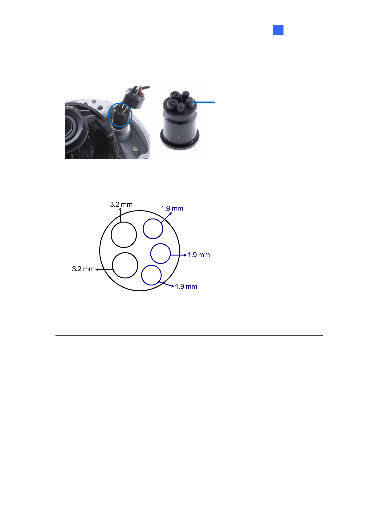
If you use cat 5 Ethernet cable, there are 5 holes each labeled with its diameter. Remove the
plugs and push the wires to the corresponding hole listed below:
Plug
Figure 1-8
3.2 mm: Audio
1.9 mm: DIDO
Figure 1-9
IMPORTANT:
1. Use the supplied ruler and leave at least 14 cm of I/O wires and 10 cm of audio
wires between their connectors on the camera and the conduit connector.
2. The plugs are used to prevent water from entering the camera housing. Keep the
unused holes plugged and save the removed plugs for future use.
3. Only thread the wires through their designated holes on the conduit connector to
make sure the wires are properly sealed.
12
Page 24
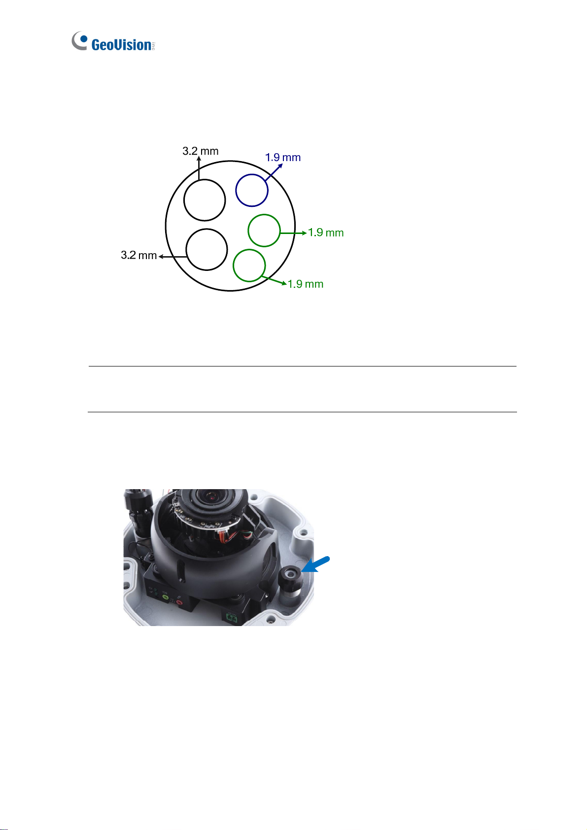
If you use cat 6 Ethernet cable, thread the DC 12V wires through the conduit connector. Refer to
the following figure for the corresponding holes and their diameters.
3.2 mm: Audio
1.9 mm: DIDO
1.9mm: DC 12V
Figure 1-10
IMPORTANT: Leave more than 10 cm of power wires between their connectors on the
camera and the conduit connector.
5. Install the Ethernet cable.
A. Rotate to remove the indicated cap and the plug inside.
Figure 1-11
13
Page 25
Introduction
1
B. Thread an Ethernet cable (the end with no RJ-45 connector) and the optional power
adapter wires from the back panel through the conduit connector.
Figure 1-12
IMPORTANT: Use the supplied ruler and leave about 14 cm of the Ethernet cable between
the connector on the camera and the conduit connector.
C. Re-install the cap. Make sure the cap is installed tightly to waterproof the camera.
6. Connect the wires to the camera and insert the memory card to the memory card slot. See
1.3 Overview, 1.5 Connecting the Camera and 1.6 I/O Connector.
Tip:
Unscrew the indicated screws and lift the camera to help you connect the wires and
insert the memory card.
14
Page 26
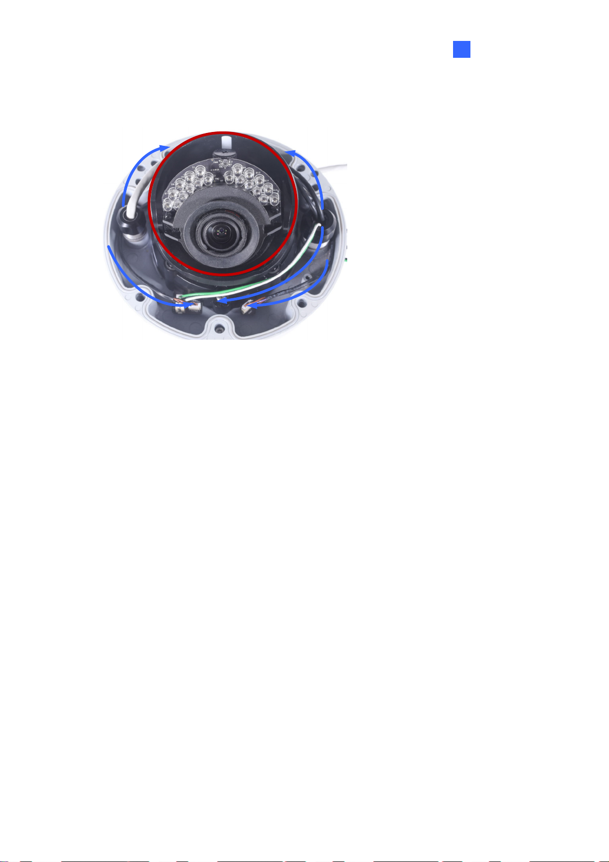
7. Sort out the wires at the back. You can have the wires come out from positions A and B or
from C.
A
B
C
Figure 1-13
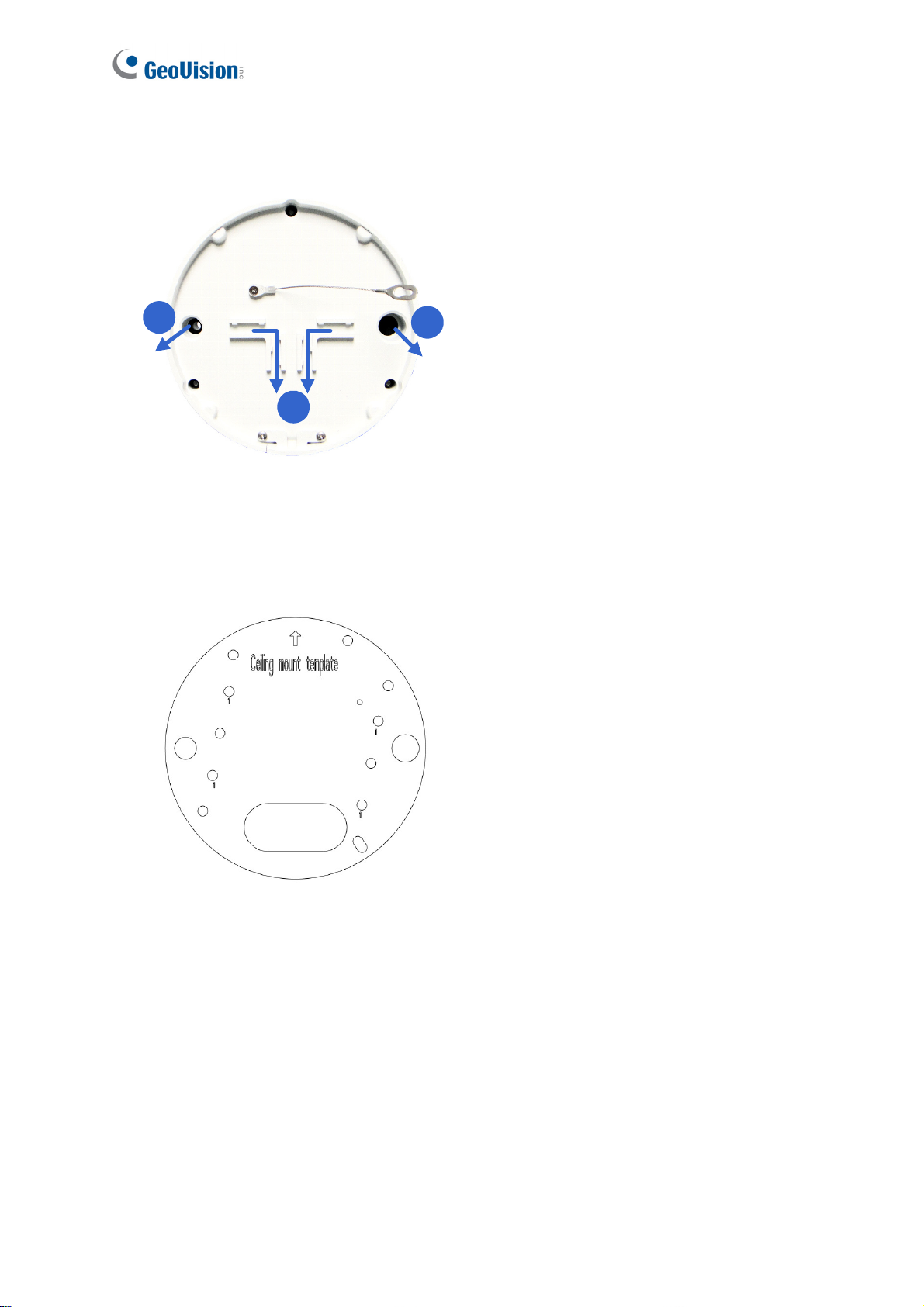
8. Secure the back plate to the ceiling.
A. Paste the sticker to the ceiling. The arrow on the sticker indicates the direction that
the camera faces.
Figure 1-14
B. Drill 4 holes for screws. The recommended ones are indicated as ‘1’.
C. Insert the screw anchors to the 4 holes.
D. Drill holes A & B or only hole C for sorting out the wires according to Figure 1-13.
E. Secure the back plate to the ceiling with the supplied screws.
15
Page 27
Introduction
1
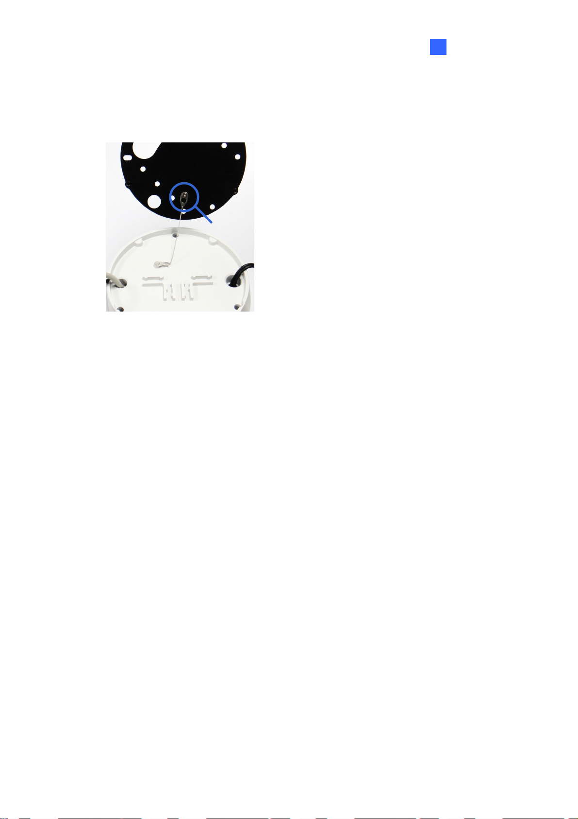
9. Secure the camera to the desired location.
A. Secure the safety lock to the camera with the screw you removed from the back plate
in Step 2.
Safety lock
Figure 1-15
B. Thread all the wires into the ceiling and connect them.
C. Secure the camera to the back plate with the supplied torx wrench.
10. Access the live view. See 2.3 Accessing Your Surveillance Image.
16
Page 28
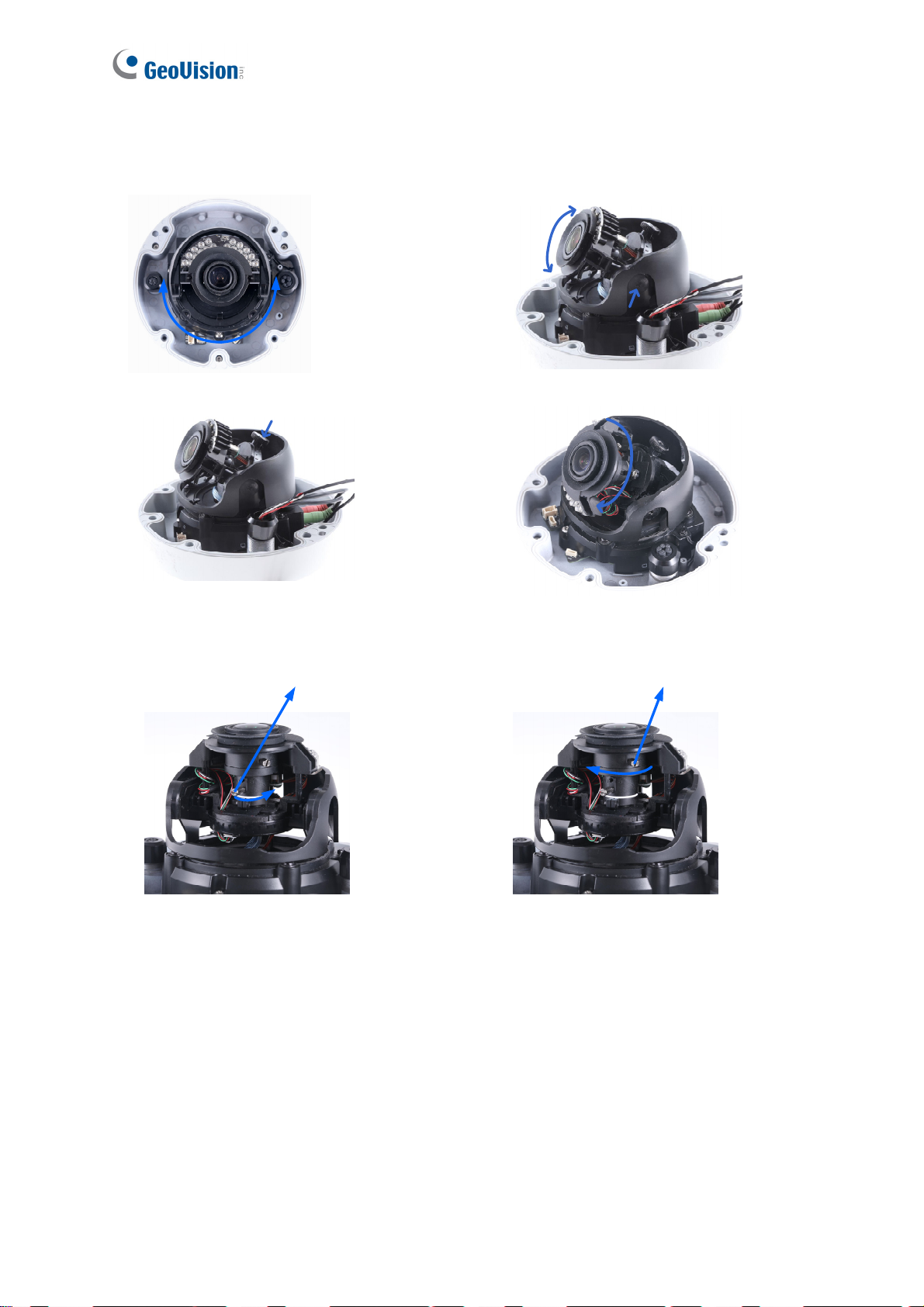
11. Adjust the angle, focus and zoom of the camera.
Pan Adjustment
Rotational Adjustment
Tilt Adjustment
Zoom Adjustment
Loosen the screw
Focus Adjustment
Loosen the screw
Figure 1-16
17
Page 29
Introduction
1
12. Replace the silica gel bag, organize the wires and secure the camera cover with the torx
wrench.
Organize
the wires
to avoid
blocking
the lens
Figure 1-17
18
Page 30
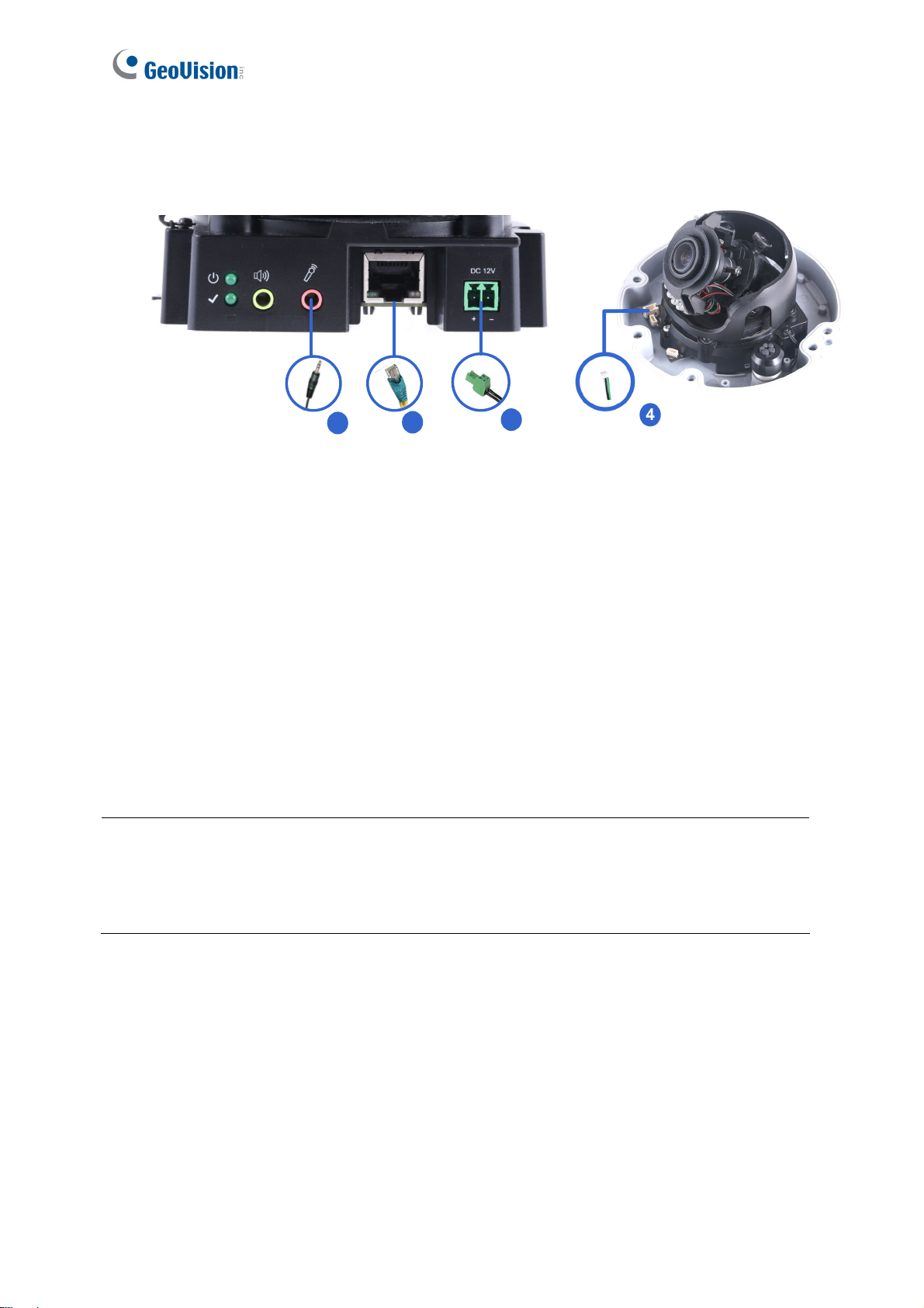
1.5 Connecting the Camera
2
1. Use a standard network cable to connect the camera to your network.
2. Optionally connect an external microphone.
3. Connect power using one of the following methods:
Plug the power adapter to the power port.
Use the Power over Ethernet (PoE) function and the power will be provided over the
network cable.
4. Optionally connect to input / output devices. For details, see 1.6 I/O Connector.
5. The status LED of the camera will be on.
Note:
1
Figure 1-18
3
1. The speaker interface will be supported in the near future.
2. The microphone interface only works with external microphone with power supply.
19
Page 31

1.6 I/O Connector
The camera supports one digital input and one digital output of dry contact.
Pin Supplied I/O Cable Function
1 Green Digital Output
2 Black GND
3 White Digital Input
For details on how to enable an installed I/O device, see 4.2.4 I/O Control.
Introduction
1
20
Page 32

Chapter 2 Getting Started
2.1 Looking Up the IP Address
By default, GV-VD8700 is assigned with a dynamic IP address by the DHCP server when the
camera is connected to the network. This IP address remains unchanged unless you unplug
or disconnect your camera from the network.
Note: If your router does not support DHCP, the default IP address will be 192.168.0.10. In
this case, it is strongly recommended to modify the IP address to avoid IP address conflict
with other GeoVision IP devices on the same LAN. To change the IP address, see 2.2
Changing the IP Address later in this chapter.
Follow the steps below to check the GV-VD8700’s dynamic IP address:
1. Download and install the GV-IP Device Utility program from
http://www.geovision.com.tw/download/product/
Note: The PC installed with GV-IP Device Utility must be under the same LAN as the
camera you wish to configure.
2. On the PC desktop, select Start, point to Programs and select GV IP Device Utility. The
Utility window appears and automatically searches for the IP devices on the same LAN.
21
Figure 2-1
Page 33

3. Click the Name or Mac Address column to sort.
Figure 2-2
Getting Started
2
4. Find the Mac Address of the camera to see its IP address.
2.2 Changing the static IP Address
When the DHCP server on your network is unavailable or disabled, the camera can be
accessed by the default IP 192.168.0.10. To modify the static IP address, log in the Web
interface to access the network setting page.
1. Open your Web browser, and type the default IP address http://192.168.0.10
2. In both Login and Password fields, type the default ID and password admin. Click Apply.
3. On the top bar, go to System Settings. Select Network and click LAN Configuration to
begin the network settings. This page appears.
.
Figure 2-3
22
Page 34

4. Select Static IP address and type the required network information.
5. Click Apply. The camera is now accessible through the static IP address.
IMPORTANT:
1. Use the dynamic DNS Service to obtain a domain name linked to the camera’s changing
IP address before you start using the dynamic IP address. For details on Dynamic IP
Address, see 4.3.2 Advanced TCP/IP and 4.3.1 LAN Configuration.
2. If Dynamic IP Address is enabled and you cannot access the camera, you may have to
reset it to the factory default settings and perform the network settings again. To restore
the factory settings, see 7.2 Restoring to Factory Default Settings.
23
Page 35

Getting Started
2
2.3 Accessing Your Surveillance Images
Two types of users are allowed to log on to the GV-VD8700: Administrator and Guest. The
Administrator has full access to all system configurations, while the Guest can only access the
live view and network status.
Once the camera is connected to the network, follow these steps to access your surveillance
images:
1. Open the Internet Explorer browser.
2. Type the IP address or domain name of the camera in the Location/Address bar of your
browser. To look up the IP address, see 2.1 Looking Up the IP Address.
3. Enter the login name and password. The administrator account has unrestricted access to
all the features and functions. The guest account is restricted to have the access of only
the live view and network status information.
The default login name and password for Administrator are admin.
The default login name and password for Guest are guest.
Figure 2-4
24
Page 36

4. A video image, similar to the example below, is now displayed on your browser.
Figure 2-5
Note: To enable the updating of images in Microsoft Internet Explorer, you must set your
browser to allow ActiveX Controls and perform a once-only installation of GeoVision’s
ActiveX component onto your computer.
25
Page 37

Getting Started
2
2.3 Configuring the Basics
Once you have logged in to the GV-VD8700, you are ready to configure some of its primary
settings through the Web interface:
Date and time adjustment: see 4.4.1 Date & Time.
Login and privileged passwords: see 4.4.2 User Account.
Network gateway: see 4.3 Network.
Camera image adjustment: see 3.2 The Control Panel of the Live View Window.
Audio settings adjustment: see 4.1.2 Audio Settings.
Video format, signal format, resolution and frame rate: see 4.1.1 Video Settings.
IMPORTANT: If you are using a 50 Hz flicker, set the Flickerless value to 50 Hz. See Video
Attributes in 3.2 The Control Panel of the Live View Window.
26
Page 38

Chapter 3 Accessing the Live View
3.1 The Live View Window
This section introduces the features of the Live View window and Network Status on the
main page.
6
7
2
1
No. Name Function
1 Play Plays live video.
2 Stop Stops playing video.
3 Snapshot
3
45
Figure 3-1
Takes a snapshot of live video.
--- See 3.3 Snapshot of a Live Video.
27
Page 39

No. Name Function
4 Full Screen Switches to full screen view.
3
Accessing the Live View
5 File Save
6 Control Panel
7 Pop-up Menu
Records live video to the local computer.
--- See 3.4 Video Recording.
Adjust these image quality settings: Video Attribute, Orientation,
Flickerless, Shutter Speed, Auto Iris, DN, DN Sensitivity,
White Balance, WDR, IR Light, and BLC.
--- See 3.2 The Control Panel of the Live View Window.
On the Live View window, right-click the image to have these
options:
Snapshot: Takes a snapshot of live videos.
Full Screen: Switches to full screen view.
PIP: Enables an inset window for a close-up view on the
video. See 3.5 Picture-in-Picture View.
Audio: Receives audio from the surveillance site.
Information: Shows the information on codec, resolution,
frames per second and transmission speed of the video
stream.
28
Page 40

3.2 The Control Panel of the Live View Window
The control panel is on the right side of the Live View window. You can adjust the settings of
the following functions on the control panel. Note these settings are only accessible for
Administrator.
The Control
Panel of the
Live View
Figure 3-2
[V
ideo Attributes] Adjusts the image quality settings.
Brightness: Adjusts the brightness of the video image.
Saturation: Adjusts the saturation of the video image.
Contrast: Adjusts the relative differences between one pixel and the next.
Sharpness: Adjusts the sharpness of the video image.
Orientation: Changes the image orientation on the Live View window.
Flickerless: The camera automatically matches the frequency of your camera’s image to
the frequency of indoor light sources, e.g. fluorescent lighting. You can also select 50 Hz
or 60 Hz manually. If these don’t match, faint light and dark bars may appear in your
images. Check the power utility to determine which frequency is used at your area.
29
Page 41

3
Accessing the Live View
Shutter Speed: Shutter speed controls the amount of light entering the image sensor
and directly impacts the quality of image presentation. A slower shutter speed allows
higher light exposure, which creates a brighter overall image and brings out background
details, but blurs moving objects. A faster shutter speed is able to capture motion at the
cost of lowering color and image clarity. The minimum shutter speed ranges from 1/30 to
1/8000 sec. In low light conditions, a fast shutter speed will lower color quality and image
clarity. In this case, select the Auto option for automatic shutter control.
Auto Iris: This function is enabled by default. Select Auto from the drop-down list when
the scene appears fuzzy and the Flickerless function does not help to improve the
situation. Select Max to set the aperture of the camera to its maximum regardless of the
illumination of the environment.
D/N: Select Auto for automatic switch between day mode and night mode depending on
the amount of light detected. Select Black and White to switch the camera to night mode.
Select Color to switch the camera to day mode. Sets the light sensor’s sensitivity of
switching between day mode and night mode, from 1 to 10. The higher the value, the
more sensitive the camera is to light.
White Balance: The camera automatically adjusts the color to be closest to the image
you are viewing. You can choose one of the four presets: Auto, Outdoor, Fluorescent,
and Incandescent. You can also choose Manual to adjust the white balance manually.
Wide Dynamic Range: Adjusts and generates clear live view when the scene contains
very bright and very dark areas at the same time. Select Strong to bring out details of the
dark areas of the scene or Normal for a balanced effect.
Defog: Select Auto to automatically enhance the visibility of images. Select Off to
disable the function.
IR Light: Select Auto to automatically enhance the visibility of images. Select Off to
disable the function.
BLC: Select Auto to automatically adjust the color intensity of scenes with strong light at
the background.
Click Apply to save the configuration after the settings are completed. The changes take
effect only after the configurations have been saved.
30
Page 42

3.3 Snapshot of a Live Video
To take a snapshot of live video, follow these steps:
1. Click the Snapshot button (No. 3, Figure 3-1). The Save As dialog box appears.
2. Specify
also choose to display the camera name and/or the date, the text color and image quality
of the snapshot.
3. Click the Save button to save the image in the local computer.
Save in, type the File name and select JPEG or BMP as Save as Type. You may
3.4 Video Recording
You can record live video to your local computer. To do so, follow the steps below:
1. Click the File Save button (No. 5, Figure 3-1). The Save As dialog box appears.
2. Specify
time length of each video clips from 1 to 5 minutes.
3. Click the Save button to start recording.
4.
To stop recording, click the Stop button (No. 2, Figure 3-1).
Save in, type the File name and move the Time Period scroll bar to specify the
31
Page 43

3
Accessing the Live View
3.5 Picture-in-Picture View
The full screen mode provides a particular type of close-up view: Picture-in-Picture (PIP).
With the Picture-in-Picture (PIP) view, you can zoom in on the video to get a close-up view.
Navigation box
Inset window
Figure 3-3
1. Right-click the live view and select PIP. An inset window appears.
2. Click the inset window. A navigation box appears.
3. Move the navigation box around in the inset window to have a close-up view of the
selected area.
4. To adjust the navigation box size, move the cursor to any of the box corners, and enlarge
or diminish the box.
5. To exit the PIP view, right-click the image and click PIP again.
32
Page 44

Chapter 4 Administrator Mode
The Administrator can access and configure the GV-VD8700 over the network. The
configuration categories include: Audio & Video Settings, Event and Alerts, Network and
Management.
Figure 4-1
Corresponding Sections for Configuration Menu
Find the topic of interest by referring to the indicated section.
4.1.1 Video Settings
4.1.2 Audio Settings
4.1 Audio & Video Settings
4.2 Events and Alerts
4.3 Network
4.4 Management
4.1.3 RTSP
4.1.4 Privacy Mask
4.1.5 Text Overlay
4.2.1 Face Recognition
4.2.2 Tampering Alarm
4.2.3 Motion Detection
4.2.4 I/O Control
4.2.4.1 Input Settings
4.2.4.2 Output Settings
4.2.5 E-mail
4.3.1 LAN Configuration
4.3.2 Advanced TCP/IP
4.3.3 IP Filtering
4.4.1 Date and Time
4.4.2 User Account
4.4.3 Tools
4.4.4 External Storage Settings
4.4.5 System Log
33
Page 45

4
Administrator Mode
4.1 Audio & Video Settings
The GV-VD8700 supports three streams, Streaming 1, Streaming 2, and Streaming 3, which
allow separate codec and resolutions settings for a single video transmission. In a
bandwidth-limited network, such as mobile phone surveillance, this multi-stream feature
allows you to view live video in lower resolution and codec (Streaming 2 / Streaming 3), and
record in highest resolution 3840 x 2160 and codec H.265 (Streaming 1) at the same time.
4.1.1 Video Settings
You can configure your video stream settings, such as H.264/H.265 video format, resolutions,
frame rate, etc. or enable / disable streaming 2 and streaming 3 in Video Settings.
Figure 4-2
Note: Streaming 3 is disabled by default. To enable streaming 3, change the video
resolution of streaming 1 to 2560 x 1440 (16:9) or lower.
34
Page 46

[Video Format] Select either H.265 or H.264 as codec type.
[Resolution]
Configure the resolution. The supported resolutions are listed below:
Streams Ratio Supported Resolution
Streaming 1
Streaming 2
Streaming 3
Streaming 1
Streaming 2
Streaming 3
16:9
4:3
3840 x 2160, 2560 x 1440, 1920 x 1080, 1280 x 720
1280 x 720, 640 x 360
640 x 360
2560 x 1920, 2048 x 1536, 1600 x 1200, 1280 x 960
1024 x 768, 640 x 480, 320 x 240
640 x 480, 320 x 240
[Frame per Second] Select a specific frame rate for video streams from the drop-down list.
[Bandwidth Management]
You can configure the bitrate settings to control bandwidth usage.
VBR (Variable Bitrate): The quality of the video stream is kept as constant as possible at
the cost of a varying bitrate. The bandwidth is much more efficiently used than a
comparable CBR. Set the image quality to one of the 5 standards: Poor, Fair, Good,
Great or Excellent.
CBR (Constant Bitrate): CBR is used to achieve a specific bitrate by varying the quality
of the stream. The bitrates available for selection depend on the image resolution.
[GOP]
Set the maximum number of seconds between every key frame. The default is 2 (seconds).
35
Page 47

4
Administrator Mode
4.1.2 Audio Settings
You can enable the microphone and adjust the audio quality to Low or Normal. Select
Built-in Microphone or External Microphone as the source of audio input.
Figure 4-3
Note: The microphone input interface only works with external microphone with power
supply. For details, see 1.5 Connecting the Camera.
36
Page 48

4.1.3 RTSP
The RTSP enables video and audio streaming to your 3G-enabled mobile phone. The RTSP
streaming is enabled by default.
Figure 4-4
[Enable Audio] Turns audio streaming on or off.
[Authentication] The ID and password of the camera are required to access the camera
through RTSP connections. This function is disabled by default.
[RTSP/TCP Port] Keep the default value 8554, or modify it if necessary.
[RTP/UDP Port] Keep the default range from 1024 to 65535, or modify it if necessary. The
number of ports for use is limited to 20.
[Max Connection] Set the maximum number of RTSP and 3GPP connections to the camera.
The maximum value is 8.
37
Page 49

4
Administrator Mode
4.1.4 Privacy Mask
You can use the Privacy Mask to block out sensitive areas on live view and recorded clips.
This feature is ideal for scenes with displays, keyboard sequences (e.g. passwords), and for
anywhere else you don’t want sensitive information visible.
Figure 4-5
1. Drag the area(s) where you want to block out on the image.
2. Click Apply to save all the settings.
3. To delete the latest privacy mask you had marked, click Delete.
4. To delete all privacy masks you had marked, click Reset and click OK.
Note: You cannot set more than 4 privacy masks on the camera image.
38
Page 50

4.1.5 Text Overlay
The Text Overlay allows you to overlay the camera name and date & time on the camera view.
Up to 33 characters can be created on one camera view. The overlaid text will be saved in the
recordings.
Figure 4-6
[Name] Type the camera name in the Name field.
[Overlaid with Camera Name] Display the camera name on the designated area on the
camera view. You can choose to place the text on the Left Top, Left Down, Right Top or
Right Down of the camera view.
[Overlaid with date stamps time] Display the current date and time on the designated area
on the camera view. You can choose to place the text on the Left Top, Left Down, Right Top
or Right Down of the camera view.
[Font Size] Choose Small, Normal or Big fonts using the drop-down list.
39
Page 51

4
Administrator Mode
4.2 Event and Alerts
For the events of motion detection, tampering alarm or I/O trigger, the Administrator can set
up triggered actions to send a snapshot by e-mail and / or activate an output device.
To have above triggered actions, you must also set the following features:
Tampering Alarm ( See 4.2.2 Tampering Alarm)
Motion Detection (See 4.2.3 Motion Detection)
Input Setting (See 4.2.4.1 Input Settings)
4.2.1 Face Recognition
You can configure the face recognition settings in this page. For details, see 5.3 Face
Recognition Basic Settings
40
Page 52

4.2.2 Tampering Alarm
Tampering Alarm is used to detect whether a camera is being physically tampered. An alarm
can be generated when the camera is moved, covered up, or out of focus. The alarm types
include output triggers and email alerts.
Figure 4-7
1. Select the Enable option.
2. Enable Dark Image to trigger an alarm when the scene turns dark, e.g. when the lens of
the camera is covered up. By default, this function is disabled.
3. Select the desired detection sensitivity under Sensitivity. The higher the value, the more
sensitive the camera is to scene changes.
4. In the Dwell Time when triggered (seconds) field, specify the time length allowed for
scene changes before an alarm is generated.
5. To trigger the e-mail alert when a tampering event occurs, enable E-Mail Output.
6. To trigger the output device when a tampering event occurs, enable I/O Output.
7. If you want the camera to ignore any movement or scene change in certain areas, click
the screen to drag areas on the camera view. Click Delete to delete the latest masked
area. Click Reset to delete all masked area.
8. Click Apply to save all the settings.
For details on setting up the e-mail server and output device, see 4.2.5 E-Mail and 4.2.4.2
Output Settings.
41
Page 53

4
Administrator Mode
4.2.3 Motion Detection
Motion detection is used to generate an alarm whenever movement occurs in the video image.
You can configure up to 4 areas with different sensitivity values for motion detection. Set up at
least one area to enable this function.
Figure 4-8
1. Select the desired sensitivity under Sensitivity. There are ten values. The higher the
value, the more sensitive the camera is to motion.
2. Drag an area on the image.
3. To create several areas with different sensitivity values, repeat steps 1 and 2.
4. Click Delete to delete the selected areas.
5. Click Reset to delete all the selected areas.
6. Select Enable to activate the e-mail alert and / or output alarm.
7. Click Apply to save the above settings.
For details on setting up the e-mail server and output device, see 4.2.5 E-Mail and 4.2.4.2
Output Settings.
42
Page 54

4.2.4 I/O Control
After installing the I/O device, you need to enable the I/O settings on the camera. For installing
the I/O device on the camera, see 1.6 I/O Connector.
4.2.4.1 Input Settings
To activate the sensor input, select Enable.
Figure 4-9
Name: Name the input in the Name field.
Normal State: Set the input state to trigger actions by selecting Open Circuit (N/O) or
Grounded Circuit (N/C).
E-Mail Output: Enable this option to send alerts to a specified e-mail address when the
input is triggered.
I/O Output: Enable this option to trigger the output once the input is activated.
For details on setting up the e-mail server and output device, see 4.2.5 E-Mail and 4.2.4.2
Output Settings.
43
Page 55

4.2.4.2 Output Settings
Select Enable to start the output device.
4
Administrator Mode
Figure 4-10
Name: Name the output in the Name field.
Normal State: Choose the output signal that best suits your device: Open Circuit (N/O)
and Grounded Circuit (N/C).
I/O Output Type: Choose Normal for the output to remain in effect until the trigger action
stops. Or choose Pulse for the output to last only for the amount of time you specified.
Pulse Time (seconds): Specify the time (seconds) for the pulse-type output to last.
44
Page 56

4.2.5 E-mail
After an event is triggered, the GV-VD8700 can send an e-mail to a remote user containing a
snapshot.
IMPORTANT: To send e-mail alert upon motion, be sure to set up the detection area on the
Motion Detection page. For details, see 4.2.3 Motion Detection.
Figure 4-11
To enable the e-mail functions:
1. Select Enable to set up e-mail notifications.
2. Server URL/IP Address: Type the server’s URL address or IP address.
3. Server Port: Type the server’s port number. Or keep the default value 25.
4. From email address: Type the sender’s e-mail address.
5. Send to: Type the e-mail address(s) you want to send alerts to.
6. Alerts interval time in minute: Specify the interval between e-mail alerts. The interval
can be between 0 and 60 minutes. The option is useful for frequent event occurrence.
Any event triggers during the interval period will be ignored.
7. If the server needs authentication, select Need authentication to login and type a
valid Username and Password to log in to the server. If the server needs a secure
connection (SSL), select This server requires a secure connection.
8. Click Apply to save the settings.
For related settings of e-mail alerts, see 4.2.2 Tampering Alarm, 4.2.3 Motion Detection,
and 4.2.4 I/O Control.
45
Page 57

4
Administrator Mode
4.3 Network
The Network section includes some basic but important network configurations that enable
the GV-VD8700 to be connected to a TCP/IP network.
4.3.1 LAN Configuration
According to your network environment, select between Static IP address or Dynamic IP
address.
Figure 4-12
[LAN Configuration]
Dynamic IP address: The network environment has a DHCP server which will
automatically assign a dynamic IP address to the camera. Click the Test DHCP to see the
currently assigned IP address or look up the address using GV-IP Device Utility.
Static IP address: Assign a static IP or fixed IP to the camera. Type the camera’s IP
address, Subnet Mask, Router/Gateway, Primary DNS server and Secondary DNS server.
Parameters Default
IP address 192.168.0.10
Subnet Mask 255.255.255.0
Router/Gateway 192.168.0.1
Primary DNS server 8.8.8.8
Secondary DNS server 8.8.4.4
For details on Dynamic DNS Server Settings, see 4.3.2 Advanced TCP/IP.
46
Page 58

[Network Status Information]
In this tab, you can view the current network status.
Figure 4-13
47
Page 59

4
Administrator Mode
4.3.2 Advanced TCP/IP
This section introduces the advanced TCP/IP settings, including DDNS Server, HTTP port,
and HTTPS.
Figure 4-14
[Dynamic DNS Server Settings]
DDNS (Dynamic Domain Name System) provides a convenient way of accessing the
GV-VD8700 when using a dynamic IP. DDNS assigns a domain name to the GV-VD8700, so
that the Administrator does not need to go through the trouble of checking if the IP address
assigned by DHCP Server or ISP (in xDSL connection) has changed.
Before enabling the DDNS function, the Administrator should apply for a Host Name from the
DDNS service provider’s website. There are 2 providers listed in the GV-VD8700: GeoVision
GVDIP or DynDNS.org.
48
Page 60

To enable the DDNS function:
1. Select Enable.
2. Select the DDNS service provider you have registered with. If you do not have a DDNS
provider, you can click on Register GeoVision DDNS Server to register the service via
GeoVision DDNS V2 and obtain a host name.
Figure 4-15
3. Type the Host Name used to link to the GV-VD8700. For the users of GeoVision DDNS
Server, it is unnecessary to fill the field because the system will detect the host name
automatically.
4. Type the User Name used to enable the service from the DDNS. The user name should
look similar to your host name. Depending on your service provider, you should add
domain name (.dipmap.com, .gvdip.com or .org) after your user name, for example,
alice.dipmap.com
5. Type the Password used to enable the service from the DDNS.
6. Click Apply to save the settings.
49
Page 61

4
Administrator Mode
[HTTP Port Settings]
The HTTP port enables connecting the GV-VD8700 to the Web. For security integration, the
Administrator can hide the server from the general HTTP port by changing the default HTTP
port of 80 to a different port number within the range of 1024 through 65535.
Figure 4-16
[HTTPS Settings]
By enabling the Hypertext Transfer Protocol Secure (HTTPS) settings, you can access the
camera through a secure protocol.
Figure 4-17
50
Page 62

4.3.3 IP Filter
The Administrator can set IP filtering to grant or restrict access to the camera. Note that you
can only set up 4 filter entries for the camera.
Figure 4-18
To enable the IP Filter function:
1. Enable IP Filtering: Enable the IP Filtering function.
2. Filtered IP: Type the IP address you want to grant or restrict access to.
3. Action to take: Select the action of Allow or Deny to be taken for the IP address(es) you
have specified.
4. Click Apply to save the settings.
51
Page 63

4
Administrator Mode
4.4 Management
The Management section includes the settings of date, time and user account. You can also
view the firmware version and execute certain system operations.
4.4.1 Date and Time
The date and time settings are used for date and time stamps on the image.
Figure 4-19
[Date & Time on IP Camera] Displays the current date and time of the camera.
[Time Zone] Sets the time zone for local settings.
[Synchronized with a Network Time Server] By default, the camera uses the timeserver of
tw.pool.ntp.org to automatically update its internal clock every 24 hours. You can change the
host name or IP setting to the timeserver of interest. To change the time of automatic update,
use the drop-down lists to specify the time.
[Synchronized with your computer or modify manually] Manually changes the camera’s
date and time. Or, select Synchronized with your computer to synchronize the camera’s
date and time with those of the local computer.
52
Page 64

4.4.2 User Account
You can change the login name and password of Administrator and the Guest user accounts.
The default Administrator login name and password are admin.
The default Guest login name and password are guest.
Figure 4-20
53
Page 65

4
Administrator Mode
4.4.3 Tools
This section allows you to execute certain system operations and view the firmware version.
Figure 4-21
[Device Settings] You can reboot GV-VD8700, restore GV-VD8700 to its factory default
settings, or import / export the system settings.
Reboot: Click Reboot for the camera to perform a software reset.
Default: Click Default to restore the camera to factory default settings.
Export System Settings: Click to export the configurations of the camera to the local PC.
Import System Settings: Click Browse to locate the system file (.config) and click
Import System Settings to import previously saved configurations to the camera. Log in
again after the Import completes.
[System Information] This field displays the firmware version of the camera.
[Firmware Upgrade] Upgrade the firmware over the Internet. For details, see 7.1 Upgrading
System Firmware.
[Enable AAC] Type the Private Key and click Upload Private Key to enable the support for
AAC format audio.
Note: AAC support is a paid service. To acquire your Private Key, contact GeoVision sales
representatives. A Private Key will be provided to you.
54
Page 66

[Language] Select the language and click Apply to save the settings.
[Disconnection Record] When the camera is disconnected from GV-DVR / NVR / VMS, the
recordings of alarm events will be temporarily saved to the camera’s memory card. The
recordings will later be uploaded to a predefined FTP server when the network connection is
resumed. After all the recordings are uploaded to the FTP, the temporary recordings on the
memory card will be removed.
IMPORTANT: Format the micro-SD card before its first use. For details, see 4.4.4 External
Storage Settings
Disconnection Record: Select On to enable the service.
Video Time Interval (minutes): Choose the duration time between 1, 2, 3, 4, or 5
minutes. When the recording starts once the camera is disconnected from GV-DVR / NVR
/ VMS, the camera will record videos for the specified time period.
Upload video to an FTP server: Select On to upload the recordings to an FTP server.
Type the settings of your FTP server in the following fields.
Server URL / IP Address: Type the URL address or IP address of the FTP server.
Server Port: Type the port number of the FTP server or keep the default value 21.
User Name: Type a valid username to log into the FTP server.
Password: Type a valid password to log into the FTP server.
Remote Directory: Type the name of the storage folder on the FTP server.
55
Page 67

4
Administrator Mode
4.4.4 External Storage Settings
You can view the memory card information in this page. Format the memory card before using
it for the first time. After being formatted, the memory card will be ready to use. To insert or
remove an SD card, see 1.3 Overview.
Figure 4-22
[Tools]
Disable: When you click Disable, the recordings that are saved to the memory card
and the snapshot of face recognition become inaccessible. The Format button and the
Unmount button become active only when you clicked Disable.
Format: Click Format to clear the content of SD card.
Unmount: Click Unmount to disengage the SD card from the camera.
Note: The recording data may be lost if you remove the memory card during recording.
56
Page 68

4.4.5 System Log
The log contains dump data that is used by service personnel for analyzing problems.
Figure 4-23
Clear: Click Clear to delete all system logs.
Download: Click Download to download all system logs to your computer.
57
Page 69

g
Chapter 5 Face Recognition
GV-VD8700 can detect for and identify persons’ faces from its predefined database. Upon
successful recognition, the name of the person identified is displayed on the live view while
the related data are recorded into the camera as a recognition event, as exemplified by the
figure below. Those who are detected but failed to be recognized within the database are
recorded as “unknown”.
Read the following sections to learn how to improve the efficiency and accuracy of face
recognition, particularly in regards to variables, such as the movement speed and facial
direction of the recognition target. It is recommended to install the camera in places where the
targets are facing right at the camera and remain focused for a maximized depth of field. It is
also essential to arrange proper lighting conditions to avoid high contrast and backlighting that
obscures the recognition target. See 5.2 Installation Flowchart for a step-by-step guide of the
installation.
Note that Face recognition is only supported by GV-VMS. When applying Face Recognition,
one GV-VD8700 can only be connected to one GV-VMS at a time. See Configuring Face
Setting, Chapter 3, GV-VMS User’s Manual.
Event Lo
Real-time
Face
Recognition
Live View
Figure 5-1
58
Page 70

5
Face Recognition
5.1 Features
Store up to 10,000 face data entries
Recognize up to 10 faces simultaneously
Maximum recognition distance of 4 meters (13.12 ft)
Minimum recognition time of 2 seconds
Customizable group settings for e-mail alerts and output alarm (requires GV-VMS)
Store up to 7 days of face recognition results and up to 3 GB of face recognition
snapshots
59
Page 71

5.2 Installation Flowchart
Follow the step-by-step guide to set up face recognition and refer to the relevant sections if
needed.
Install the camera at the ideal camera posion
5.3 Ideal Camera Position
1.4 Installing the Camera
Adjust Illumination of the installation site
5.4 Adjusting Illumination
Access the camera
Chapter 2 Getting Started
Enroll Face Data
5.5 Enrolling Face Data
5.5.1 Photo Requirements
Activate Face Recogn ition
5.6.1 Settings
Searching Face Recognition Results
5.6.4 Events
60
Figure 5-2
Page 72

5
Face Recognition
5.3 Ideal Camera Position
Face recognition works best when the camera is properly aligned with the face of the
recognition target. When installing the camera, make sure to take the relevant environmental
factors into account, such as height, distance, focus and range, to achieve optimal recognition
results. A well-lit hallway is an example of an ideal location, where the direction of movements
of the recognition targets can be easily predicted. Make sure you meet the criteria below when
installing the camera:
Less Ideal Installation Scenario Recommended Installation Scenario
A height of > 2 m or < 2 m An approximate height of 2 m
A distance of > 4 m or < 4 m An approximate distance of 4 m
Wide angle end Telephoto end
> 15° of lateral deviation < 15° of lateral deviation
Results
Less Accuracy Better Accuracy
Height & Distance: The more aligned the camera is to the front view of the face, the
better the recognition results. Mount the camera at a 15-degree angle to the face of the
recognition targets, or at a height of approximately 2 m (6.56 ft). The recognition result is
at its best at a distance of approximately 4 m (13.12 ft).
<15°
<15°
2M
4M
Figure 5-3
61
Page 73

Focus: A large depth of field not only ensures an appropriate image size for the faces of
the recognition targets, but also allows them to stay in focus for a longer period of time,
thereby increasing the recognition accuracy. Calibrate the lens at the telephoto end for
effective recognition at its optimal recognition distance of 4 m (13.12 ft).
Loosen the screw
Telephoto End
Figure 5-4
Range: The recognition result is at its best when the target walks straight to the camera.
When the target deviates laterally, recognition is still possible as long as the target stays
within a 15 degree range. The camera is unable to recognize the faces when the
deviation exceeds 15 degrees.
<15°
Recognizable
<15°
Recognizable
>15°
Unrecognizable
Figure 5-5
62
Page 74

5
Face Recognition
5.4 Adjusting Illumination
After installing the camera properly, it is required to adjust the environment’s lighting since the
recognition process may vary depending on the illumination. Follow the guidelines below to
set up the environment’s lighting according to Daytime, Nighttime and Low Illumination
(WDR) recognition needs.
5.4.1 Daytime
Make sure the following criteria are met to achieve optimal recognition performance in
daytime:
Less Ideal Installation Scenario Recommended Installation Scenario
Insufficient Lighting Sufficient Lighting
Fast Moving Target
Target Moving at a Constant Speed
(1/60 Second Shutter Speed)
Results
Less Ideal Recognition Performance Best Recognition Performance
Lighting: Sufficient light is required for effective recognition results, as moving targets
often cause motion-blurred images under insufficient lighting.
Shutter Speed: Adjust the shutter speed to 1/60 seconds manually when the camera is
installed in places with high flow of people such as hallways.
63
Page 75

5.4.2 Nighttime
If you found recognition results to be less optimal at night, you can use extra IR LED tubes as
a lighting aid for the camera or create extra face data under IR LED illumination. Both
methods can be applied to achieve optimal face recognition results at night.
Figure 5-6
Extra IR LED Tubes: Install additional IR LED tubes at the surveillance site to illuminate
the recognition range.
With the aid of
Internal IR LED only
extra IR LED Tube
Relying solely on the internal IR
LED can cause overexposure,
which may lead to misrecognition
Increasingly better recognition
results occur under stable
illumination of extra IR LED tubes.
Figure 5-7
Enroll face data under special light conditions: Enroll additional face data for objects
under IR LED illumination. See 5.5 Enrolling Face Data.
64
Page 76

5
Face Recognition
5.4.3 Low Illumination (WDR)
Intense lighting contrast in an environment may cause ineffective recognition results. In this
case, there are two ways to compensate for recognition accuracy:
Apply Wide Dynamic Range (WDR) or Back Light Compensation (BLC): By default,
the WDR function is enabled. If recognition results are still ineffective with the WDR on,
adjust the WDR settings to Strong and enable the BLC settings. To adjust WDR or BLC
settings, see 3.2 The Control Panel of Live View Window.
Without Applying WDR
WDR WDR (Strong) and BLC
or BLC
Figure 5-8
Enroll face data under special light conditions: Enroll additional face data for objects
under WDR and BLC illumination. See 5.5 Enrolling Face Data.
65
Page 77

5.5 Enrolling Face Data
After the camera and the environment’s lighting are set, it is required to create the face data
by adding photos of the persons to be recognized into the Face Database of GV-VD8700.
To enroll Face Data:
1. Click System Settings. Then in the left menu, click Events and Alerts, select Face
Recognition and click the Management tab.
2. Click Add New Record
appears.
Figure 5-9
on the upper-right corner. A dialog box
66
Page 78

3. Fill out the following information:
5
Face Recognition
Figure 5-10
Name: Type a desired name for the person.
Organization: Type a desired organization name for the person.
Group: Select from a list of ten groups in which the person shall be categorized
under. The ten groups include Allowed, Disallowed, Normal and Group 4 to 10.
Browse: Click to add portrait photos or snapshots, as face recognition data, for the
person. Make sure the photos meet all of the requirements as specified in 5.5.1
Photo Requirements.
4. Click Save to save the face data. If the photo(s) selected don’t meet the required criteria,
an Error message will appear.
5. To add photos to or edit an existing profile, click the Edit Record icon
in Figure 5-9.
67
Page 79

Note:
1. You can use the Group setting to trigger e-mail alerts and output alarms. The output
alarms to be triggered by Group setting needs to be configured with a GV-I/O Box
connected to GV-VMS. See Configuring Face Setting, Chapter 3, GV-VMS User’s
Manual.
2. Groups 4-10 appear only when the camera is connected to GV-VMS V17.1 or later and
the Face Recognition function is activated.
3. You can only change the group name through GV-VMS V17.1 or later.
4. It is possible to create two face data with identical names in the database. In this case,
simply click OK when you are prompted by the pop-up message.
68
Page 80

5
Face R
ecognition
5.5.1 Photo Requirements
For face recognition to work, it is required for the photos to meet the following criteria:
Each photo should consist of only one face.
Size of the face in the photo is around 120 ~ 250 pixels.
The file size of the photo cannot exceed 350 KB.
Only JPG / JPEG format is supported.
Make s
See t
he examples below:
ure the face of the person does not occupy more than 50% of the image.
Best Example Example of Failure - 1 Example of Failure - 2
The face occupies 50% of
the image. The size of the
he face occupies more
T
than 50% of the image.
The size of the person’s
face is less than 120 pixels.
person’s face is around
120 ~ 250 pixels.
Figure 5-11
he accuracy of the face recognition can be improved by conforming to the suggestions
T
below:
Enroll 5 or more photos for each person with different angles
Make sure the lighting is sufficient to reduce shadows on faces.
Avoid glare from the glasses that obscures the eyes.
Take the photo of the person from a distance of about 1 ~ 1.5 meters (3.2 ~ 4.9 feet)
away from the camera to minimize image distortions.
69
Page 81

More photos with different variations and under different lighting conditions can increase the
recognition performance. It is recommended to include at least a front view (close view
and distant view), a tilted-left view, a tilted-right view, and a 20 degree view from above
view per face ID.
Front View
Front View
Tilted-Left
Tilted-Right
20 Degree View
from above
(Close View)
(Distant View)
View
View
view
Figure 5-12
See the table below for more examples. You can enroll a maximum of 20 photos per Face ID.
Internal IR LED
Smiling View
Glasses
Removed view
20 Degree View
from below
Internal IR LED
(Glasses
(with Glasses)
Removed)
Figure 5-13
Note: You can take the portraits with different sources of light, such as IR LED, WDR or
Back Light Compensation.
Certain articles and / or angle of view may pose limitations to the accuracy of face recognition.
See Appendix B. Limitations to Face Recognition to avoid them if the recognition results are
still ineffective.
70
Page 82

5
Face Recognition
Using Snapshots
If for any reason standard portrait photos cannot be taken, you can increase the recognition
performance by using snapshots taken from the surveillance site. Possible scenarios may
include:
Nighttime Recognition: where the installation site may not be subjected to IR LED
enrollment conveniently.
Special Entities: who are unwelcomed or who refuse to comply with the standard
enrollment process.
Frequently Misrecognized Entities: whose personal photos were not taken properly,
which leads to deficient recognition results.
To use snapshots from live videos, see 3.3 Snapshot of a Live Video.
To use snapshots from recorded videos, see 3.4 Video Recording. Capture the desired
image and use it as the source for face data enrollment.
To use snapshots from events, go to Event and Alerts and click Events. Right-click the
snapshot under Image (Snapshot of Events, Figure 5-17) and click Save image as… to save
the cropped image as the future source for face data enrollment. See 5.6.4 Events.
After the snapshots are saved, edit them so that they meet the requirements as specified in
5.5.1 Photo Requirements.
71
Page 83

5.6 Face Recognition Basic Settings
5.6.1 Settings
After the camera is installed, select Enable to activate face recognition and click Apply.
Figure 5-14
[Confidence Level] Select the confidence level from the drop-down list for different precision
requirements.
At level 50, the camera identifies similar faces from the face database when a person
passes by.
At level 55, the camera recognizes the passing person with increased accuracy.
At level 60, it is required for the person to be seen directly in front of the camera at a
proper distance with his / her face captured under good lighting condition for the
recognition to work.
[Export Face Database] Export the face database of the camera into a zip file and save it on
your PC, to be backed up or used for other cameras.
[Import Face Database] Import a face database into the camera.
IMPORTANT:
1. Importing a face database into the camera will replace the existing database. Back up
the existing database before importing a new database into the camera.
2. After the new database is imported, make sure that your local computer is supported
by Abode Flash Player. Otherwise, the face database (Figure 5-16) and event log
(Figure 5-17) will become inaccessible.
72
Page 84

5
Face Recognition
5.6.2 License
The license key is programmed by default. When the license key is programmed properly,
the settings page will show Face recognition license activated.
Figure 5-15
73
Page 85

5.6.3 Management
In the Management section, you can enroll, review, search and edit the enrollment data of a
specific entity, including pictures and name.
Clicktoenrollnewfacedataintothe
Clicktosearchparticular
facedata
Namesandgroupsoffacedata
camera’sdatabase
Clicktoedit
thefacedata
Clicktodelete
thefacedata
Clicktodeleteallfacedata
Figure 5-16
[Filter Name] Type Name and click Search to retrieve the face data of a particular person.
[Add new record] Click to create new face data. See 5.5 Enrolling Face Data.
[Edit] Click the
[Delete] Click the
button to edit the face data. See 5.5 Enrolling Face Data.
button to delete the face data.
[Clear all people] Click the button to delete all face data in the face database.
Note: When using the Search function, the results will include all entries containing the
keyword searched for, unless further specified. Suppose the face database contains
entries of “Alvin Martin” and “Alvin Huang”, both results are shown when using “Alvin” as
the keyword. When the keyword is further specified as “Alvin Huang”, “Alvin Martin” is
excluded from the search results.
74
Page 86

5
Face Recognition
5.6.4 Events
In the Events section, you can view, search and access the face event log and history. The
camera keeps the events for 7 days or up to 160,000 events. After reaching either the 7 days
or the 160,000 events quota, the oldest event is recycled. Make sure you conform to the
following integration specifications when configuring the recognition event log using GV-VMS:
When applying Face Recognition, one GV-VD8700 camera can only be connected to
one GV-VMS host at a time.
Closest Match
in the camera’s
database
Snapshot of EventEvent Time Target’s Name
Second Closest
Match
in the camera’s
database
Third Closest
Match
in the camera’s
database
Figure 5-17
To search for log data:
1. Specify the Start Time and End Time of the log data.
2. Click Query to display the search results.
3. Choose to display 10, 25, or 50 query entries from the drop-down list.
4. To locate specific events, select Advanced Search. The search field appears.
Figure 5-18
75
Page 87

Filter Name: Type the name of the person to filter for the person’s recognition
events.
Filter Group: Select among Normal, Allowed, Disallowed, and Group 4-10 from
the drop-down list to show the event log of all persons who belong to that group.
Filter Organization: Type the organization to display all events with the members
belonging to that organization.
Filter Confidence Name: Type the name of the person and specify the confidence
interval, from Min Score to Max Score, in which it is searched for. For instance, if
Jack is searched with a Min Score of 0 and Max Score of 1, all results of Jack
recorded under Conf0 to Conf1 will be displayed.
Conf0: The closest match, of Face ID from the database, to the recognition
event.
Conf1: The second-closest match, of Face ID from the database, to the
recognition event.
Conf2: The third-closest match, of Face ID from the database, to the
recognition event.
5. To see the full snapshot of the event, double-click the snapshot under Image.
Figure 5-19
6. Right-click on the image for the following list of options:
Save picture as: Save the picture as the format of your choice.
E-mail picture: Send the picture in the size of your choice to the e-mail address set
up previously. For details on setting up e-mail notification, see 4.2.5 E-mail.
Print picture: Print the picture by your printer.
Go to My Pictures: Open the My Picture folder in Windows.
Set as background: Set the image as the background of your PC.
76
Page 88

5
Face Recognition
7. To update and show query results periodically, select Auto Polling. Type the time
interval in minutes in the next field. See Figure 5-18.
Note:
1. Your GV-VD8700 must be in the same time zone with your PC to display the
recognition event history.
2. When using the Search function, the results will include all entries containing the
keyword searched for, unless further specified. Suppose the face database
contains events related to “Alvin Martin” and “Alvin Huang”, both results are shown
when using “Alvin” as the keyword. When the keyword is further specified as “Alvin
Huang”, “Alvin Martin” is excluded from the search results.
3. The texts and the snapshots of the face events have different recycle thresholds as
they are stored in the camera’s storage space and the memory card respectively.
As a result, some older events may be displayed as text-only events when the
snapshots are removed due to the memory card reaching its 3GB limit while the
event texts are still in place.
77
Page 89

Chapter 6 Recording and Playback
The camera can only record video and audio to the camera’s memory card upon
disconnecting from GV-DVR / NVR / VMS. To do so, make sure that the micro-SD card is
inserted into the memory card slot (No.15, Figure 1-2), formatted (see 4.4.4 External Storage)
and enable the Disconnection Record function. For details, see 4.4.3 Tools. To set up audio
recording, see 4.1.2 Audio Settings.
6.1 Playback Using the Memory Card
You can access the recordings from your local PC by connecting the memory card to a
memory card reader. Since the video files are saved in the MPEG4 format, they are
accessible by any video player that supports the format. See 4.4.4 External Storage to
remove the micro-SD card safely.
78
Page 90

Chapter 7 Advanced Applications
This chapter introduces advanced applications.
7.1 Upgrading System Firmware
GeoVision periodically updates the latest firmware to the company website. You can update
the camera’s firmware through the Web interface or GV-IP Device Utility.
7.1.1 Using the Web Interface
1. On the top bar, go to System Settings. Under Management, select Tools and click
Firmware Upgrade.
Figure 7-1
2. Click the Browse button to locate the firmware file (.img) saved at your local computer.
3. Click the Upload button to start upgrading.
79
Page 91

7.1.2 Using the GV-IP Device Utility
The IP Device Utility provides another way to upgrade the firmware. Note the computer used
to upgrade firmware must be under the network of the camera.
1. Download and install the GV-IP Device Utility from
http://www.geovision.com.tw/download/product/
2. Double-click the GV-IP Device Utility icon created on your desktop. This dialog box
appears.
Figure 7-2
3. Click the Search button to locate the available camera on the same LAN. Or click the New
button and assign the IP address to locate the camera on the Internet.
4. Double-click the camera in the list. This dialog box appears.
.
Figure 7-3
80
Page 92

5. Click the Firmware Upgrade tab. This dialog box appears.
Advanced Applications
7
Figure 7-4
5. Click the Browse button to locate the firmware file (.img) saved at your local computer.
6. Type Password, and click Upgrade to start the upgrade.
81
Page 93

7.2 Restoring to Factory Default Settings
If for any reason the camera is not responding correctly, you can reset it to its factory default
setting by using the camera’s Web interface or by operating directly on the camera.
7.2.1 Using the Web Interface
1. On the Web interface, go to System Settings.
2. In the left menu of Web interface, select Management and click Tools.
3. Under the Device Settings tab, click the Default button to restore the factory default
settings, and the current IP address of the camera will be kept.
4. To restore the camera and its IP address to factory default settings, select Restore All
Default Setting Without Keeping Current IP Address and click Default.
7.2.2 Directly on the Camera
1. Keep the power and network cables (or PoE) connected to the camera.
2. Press and hold the Default button on the camera body. The status LED blinks. This shall
take about 8 seconds.
Default button
Figure 7-5
3. Release the Default button when the status LED stops blinking. The process of loading
default settings is completed and the camera reboots automatically.
82
Page 94

Chapter 8 DVR / NVR / VMS Configurations
The GV-DVR / NVR / VMS provide a full range of video management functions and features,
such as video viewing, recording, playback, alert settings and more. The following are the
integration specifications:
GV-DVR / NVR version 8.7.4.0 or later or GV-VMS version 17.1 or later is required.
Face Recognition is only supported by GV-VMS. When applying Face Recognition, one
GV-VD8700 can only be connected to one GV-VMS at a time. See Configuring Face
Setting, Chapter 3, GV-VMS User’s Manual.
The GV-VD8700 supports up to 8 streams of connection.
When a GV-VD8700 is connected to IE browser or GeoVision CMS applications, it takes
up 1 stream when it is connected to GV-DVR / NVR / VMS, it takes up 2 streams.
Note: By default, GV-VD8700 is in dual streams and will take up 2 streams when
connected to GV-DVR / NVR / VMS.
TCP/ IP
GV-VD8700
GV-DVR / NVR / VMS
GV-VD8700
Figure 8-1
83
Page 95

8.1 Setting Up IP Cameras on GV-DVR / NVR
Follow the steps below to manually connect your GV-VD8700 to GV-DVR / NVR.
Note: The following instructions are based on GV-DVR / NVR V8.7.4.0 software and user
interfaces.
1. On the GV-DVR / NVR’s main screen, click the Configure button, select System
Configure, select Camera Install and click IP Camera Install. This dialog box appears.
Figure 8-2
2. To automatically set up an IP camera, click Scan Camera to detect any IP cameras on the
same LAN.
3. Double-click GV-VD8700 and type the camera’s user name and password.
84
Figure 8-3
Page 96

4. Click OK and this dialog box appears.
8
DVR / NVR / VMS Configurations
Figure 8-4
5. Click OK to add the camera to the connection list.
6. Click the listed camera and select Display position to map the IP camera to channel on
the GV-DVR / NVR.
Figure 8-5
7. The Status column now should display “Connected”. Click OK. The dome view is
displayed on the selected channel of GV-DVR / NVR.
85
Page 97

8.1.1 Customizing Camera Settings on GV-DVR / NVR
After the GV-VD8700 is connected and assigned with a display channel, you can configure
the camera’s settings such as frame rate, codec type and resolution. Right-click the camera to
see the following list of options:
Figure 8-6
Disconnect camera: Ends the connection to the GV-IP camera. You can change the
settings of the camera after the camera is disconnected.
Change Position: Changes the grid position where the live view is displayed on the main
screen.
Delete camera: Delete the camera on the camera list.
Remote Camera Settings: Accesses the Web interface.
Network Time Out: When network disconnection exceeds the specified time period, the
camera status will be displayed as Connection Lost.
On Demand Display: When the camera supports dual streaming with different
resolutions, select On Demand Display to enable automatic adjustment of live view
resolution.
Live-view frame rate control (Sub stream): Sets the live view frame rate of the sub
stream to help reduce the CPU usage. Select one of the following options when the live
view codec of the camera is set to H.264 or H.265:
Maximum Live-view Frame Rate: Views the video at the maximum frame rate
possible.
Live-view Key Frame only: You can choose to view the key frames of the videos
only instead of all frames on the live view. This option is related to the GOP setting of
the IP camera. For example, if the GOP value is set to 30, there is only one key frame
among 30 frames.
86
Page 98

8
DVR / NVR / VMS Configurations
Live-view frame rate control (Main stream): Sets the live view frame rate of the main
stream with higher resolution when On Demand function is enabled. Refer to Live-view
frame rate control above to see the options available.
Frames to keep in live view buffer: Specifies the number of frames to keep in the live
view buffer.
Recording Codec Format: Specifies whether to record in standard or GeoVision type of
H.264 / H.265 codec.
ONVIF Settings: Adjusts the camera’s video settings when connecting through ONVIF
protocol. See 8.1 Setting Up IP Cameras on GV-DVR / NVR.
87
Page 99

8.2 Setting Up IP Cameras on GV-VMS
Follow the steps and conform the integration specification below to manually connect your
GV-VD8700 to GV-VMS.
When applying Face Recognition, one GV-VD8700 camera can only be connected to
one GV-VMS host at a time.
Note: The following instructions are based on V17.1 software and user interfaces.
1. To access the IP Device Setup page, click Home
Configure
and select Camera Install.
Figure 8-7
, select Toolbar , click
2. Click Automatic Setup.
88
Page 100

8
DVR / NVR / VMS Configurations
3. Double-click GV-VD8700 and type the User name and Password of the camera.
Figure 8-8
4. Click OK and this dialog box appears.
Figure 8-9
89
 Loading...