

Page 1
Hardware Installation Guide
GV-Vandal Proof IP Dome
GV-VD1530 / 1540 / 2430 / 2440 / 2530 / 2540
GV-VD2540-E / 3430 / 3440 / 5340 / 5340-E
Thank you for purchasing GV-Vandal Proof IP Dome. For advanced information
on how to use the GV-Vandal Proof IP Dome, please refer to GV-IPCam H.264
User's Manual and Quick Start Guide online.
© 2014 GeoVision Inc. All rights reserved.
2014/11
English
VDV3-QG-A
61-DMVDV3Q-0001
Page 2

Important
Note for Connecting to GV-System / GV-VMS
The GV-IPCAM H.264 is designed to work with GV-System / GV-VMS, a
video management system. Note the following when GV-IPCAM H.264 is
connected to GV-System / GV-VMS:
1. By default, the images are recorded to the memory card inserted to the
GV-IP Camera H.264.
2. Once the camera is connected to GV-System / GV-VMS, the resolution
set on GV-System / GV-VMS will override the resolution set on the
camera’s Web interface. You can only change the resolution settings
through the Web interface when the connection to GV-System / GV-VMS
is interrupted.
Note for Recording
1. By default, the images are recorded to the memory card inserted to the
GV-IP Camera H.264. Make sure the Write recording data into local
storage option is enabled. If this option is disabled, the camera will stop
recording to the memory card while the live view is accessed through
Web browsers or other applications. For details, see Video Settings,
Administrator Chapter, GV-IPCam H.264 User’s Manual online.
2. Mind the following when using a memory card for recording:
● Recorded data on the memory card can be damaged or lost if the
data are accessed while the camera is under physical shock, power
interruption, memory card detachment or when the memory card
reaches the end of its lifespan. No guarantee is provided for such
causes.
● To avoid power outage, it is highly suggested to apply a battery
backup (UPS).
● For better performance, it is highly suggested to use Micro SD card of
MLC NAND flash, Class 10.
● Replace the memory card when its read/write speed is lower than 6
MB/s or when the memory card is frequently undetected by the
camera.
Page 3
3. It is recommended to use memory cards of the following setting and
specifications:
● Apply a battery backup (UPS) to avoid power outage.
● Use Micro SD card of MLC NAND flash, Class 10 for better
performance.
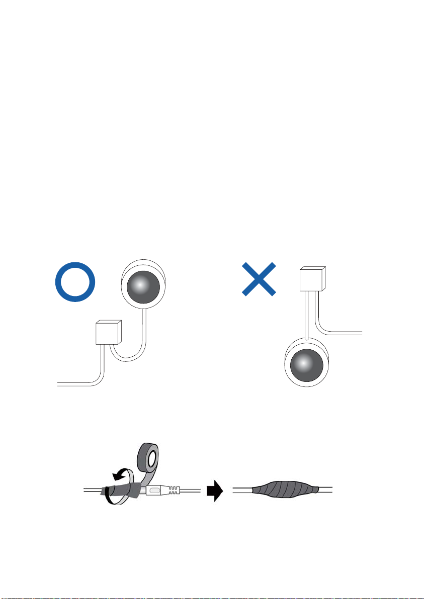
Note for Installing Camera Outdoor
1. The camera is set up above the junction box to prevent water from
entering the camera along the cables.
2. Any PoE, power, audio and I/O cables are waterproofed using waterproof
silicon rubber or the like.
Page 4
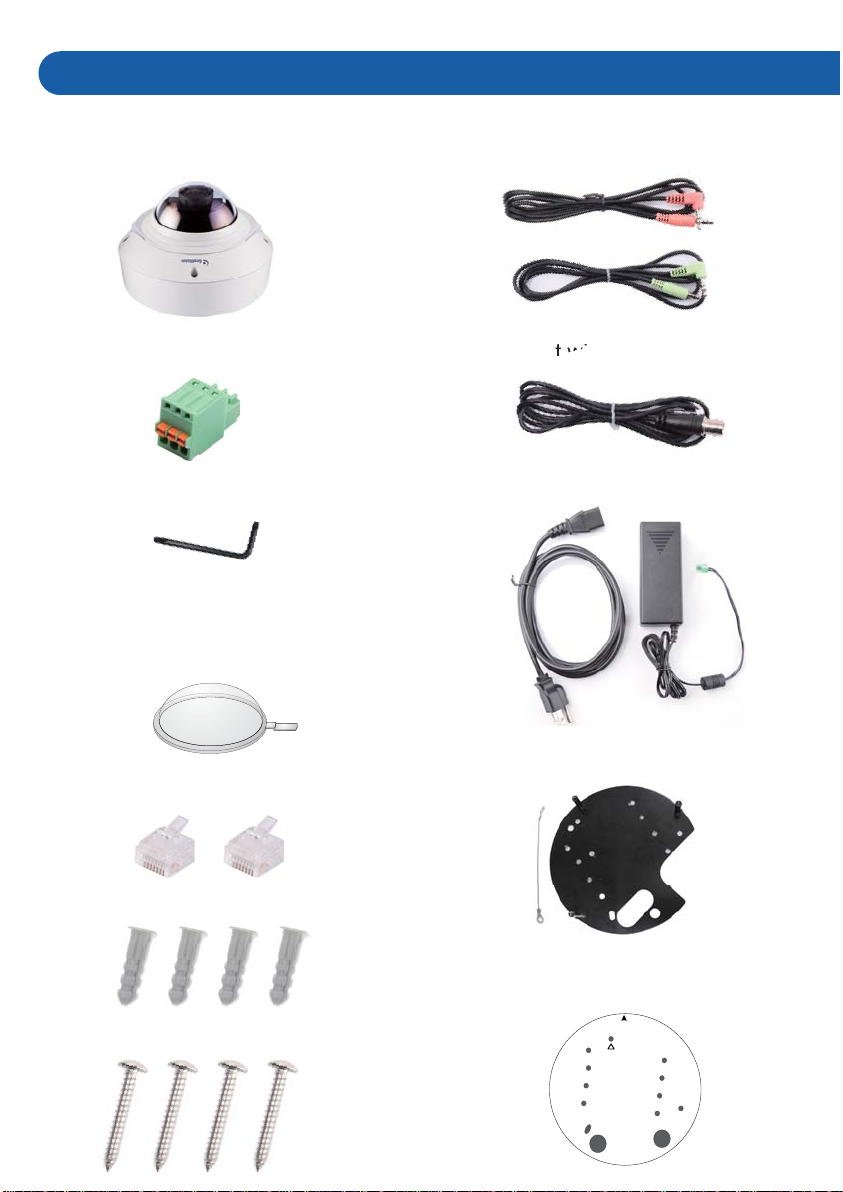
Packing List
s
ou
● Vandal Proof IP Dome
● 3-Pin Terminal Block
● Torx Wrench
● Focus Adjustment Cap
(for GV-VD1530 / 2430 / 2530 /
3430 only)
● Audio wires
● TV out wire
● Power Adapter
● RJ-45 Connector x 2
● Screw Anchor x 4
● Long Screw x 4
● Back Plate
● Installation sticker
Ceiling mount template
1
1
1
Page 5
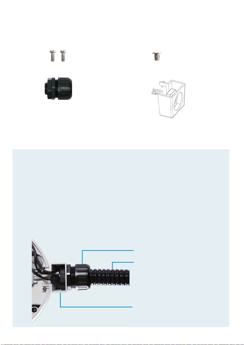
● Short Screw x 2 ● Flat Screw
● PG21 Conduit Connector ● Conduit Converter
● Silica Gel Bag
● Sticker (for Silica Gel Bag)
● Ruler
Note:
1. Power adapter can be purchased upon request.
2. You can choose to run the wires through a conduit pipe. After you
have threaded all the wires, install the supplied conduit converter and
plastic PG21 conduit connector with a self-prepared 1/2’’ conduit
pipe to the camera. Power will have to be supplied through a PoE
adapter because the power adapter wire does not fit in a 1/2” pipe.
You will have to purchase your own PG21 conduit connector if you
want to use a 3/4” or 1” pipe.
Plastic PG21 conduit connector
Conduit pipe
Conduit converter
Page 6

Overview
Default Button
LED Indicator
Audio In
LAN / PoE
Video Out
Memory Card Slot
Audio Out
DC12V / AC24V
IO Terminal Block
Rotational Screw
Cable Seal
Tilt Screw
Conduit Connector
Silica Gel Bag
Page 7

Installation
3
The Vandal Proof IP Dome is designed for outdoors. With the standard
package, you can install the camera on the ceiling.
Wiring the Camera
Rotate to remove the
1
2
indicated cap and the
plug inside.
Thread an Ethernet cable (the end with no RJ-45 connector) from
the back panel through the cable seal and re-install the cap.
3
Use the supplied ruler and
leave about 11 cm of the
Ethernet cable between
the connector and the
cable seal.
11 cm
Page 8

4
Thread wires into the camera.
A. Unscrew the conduit
connector from the back.
Conduit Connector
B. Unplug the conduit connector inside the housing and
disassemble the connector composed of 4 parts.
1 2 3 4
C. Remove the terminal block from the power adapter.
-
+
D. Thread the audio wires (optional), TV out wire (optional),
adapter wires and I/O wires (optional) through the conduit entry
and then through part 1, 2, 3 and 4 of the conduit connector.
Continued on the reverse
Page 9

For part 2, there are 8 holes each labeled with its diameter.
Remove the plugs and push the wires to the corresponding
holes listed below:
plug
2.6mm
2.6mm
1.8mm
5
2.6 mm: Audio, BNC
2 mm: DC12V / AC24V
1.8 mm: DIDO
2.6mm
2mm
2mm
1.8mm
1.8mm
Use the supplied ruler and leave about 10 cm of power and I/O
wires between their connectors and the cable seal; leave at
least 11 cm of audio/TV-out wires between their connectors and
the cable seal.
11 cm
10 cm
Page 10

IMPORTANT:
1. Keep the unused holes plugged to waterproof the camera and
save the removed plugs.
2. Only thread the wires through their designated holes on the
conduit connector to make sure the wires are properly sealed.
Tip:
1. To make the threading easier, it is advised to thread the wires
in the order described here.
2. Use a pair of pliers to help you pull the wires through the
camera.
6
Connect the wires to the camera.
A. Install the terminal blocks to the power adapter and I/O devices.
For details, see 4. Connecting the Camera later in the
Installation Guide
B. Install the supplied RJ-45 connector to the Ethernet cable.
C. Plug all the connectors to the camera panel.
D. Arrange the wires in the conduit connector and re-install it to the
camera.
Tip: Unscrew the indicated screws and lift the camera to help you
connect the wires.
Page 11

7
Sort out the wires at the back. You
can have the wires come out from
position A, B or both. The
instructions here describe sorting
wires for position A.
From the back of the camera housing, unscrew and rotate the
plate to one side, sort out the wires and secure the plate back.
Plate
A
B
Mounting to the Ceiling
8
Secure the back plate to the ceiling.
A. Paste the sticker to the ceiling. The arrow on the sticker
indicates the direction that the camera faces.
Ceiling mount template
1
1
1
Page 12

B. Drill 3 holes for screws. The recommended ones are indicated as
‘1’.
C. Insert the screw anchors to the 3 holes.
D. Depending on how you want to run the wires (see step 7). Drill the
right hole (on the installation sticker) for position A and the left for
position B or both if required.
E. Secure the back plate to the ceiling with long screws.
9
Secure the camera to the ceiling
A. Secure the safety lock to the camera using a short screw.
Use flat screw for number 1 and short screw for number 2.
1
2
B. Thread all the wires into the ceiling and connect them.
C. Secure the camera using the torx wrench.
Page 13

Adjusting Camera's Angle
10
11
Access the live view. For details, see Accessing the Camera,
Chapter 16, GV-IPCAM H.264 Quick Start Guide online.
Adjust the camera’s angle, focus and zoom of the camera.
Pan Adjustment Tilt Adjustment
Rotational Adjustment
12
Replace the silica gel bag and secure the camera cover using
the torx wrench.
Page 14

IMPORTANT:
1. The gel bag loses its effectiveness when the dry camera is
opened. To prevent the lens from fogging up, replace the silica
gel bag every time you open the camera and conceal the silica
gel bag within 2 minutes of exposing to open air.
2. For each newly replaced silica gel bag, allow it to absorb
moisture for at least 5 hours before operating the camera.
3. Make sure the housing cover is properly secured to prevent
water from entering and damaging the inner housing.
4. If the center of the camera view is less than 25° to the ceiling,
or lower than the grey line (as illustrated below), disassemble
the indicated ring so the view is not obstructed. However, with
the ring disassembled, slight reflections may occur.
Center of the view
Page 15

Connecting the Camera
4
3
Connect the camera to power, network and other wires needed.
Connecting the Power Cable
There are two ways to supply power to the camera:
● Use a Power over Ethernet (PoE) adapter to connect the camera to
the network, and the power will be provided at the same time.
● Plug the power adapter to the terminal block by inserting the wire with
white lines to the right pin and the other wire to the left pin.
-
+
Connecting the I/O Device
The Vandal Proof IP Dome support one digital input and one digital output of
dry contact.
Function
Pin
Digital Output
1
GND
2
Digital Input
123
For details on how to enable an installed I/O device, see I/O Settings,
Administrator Mode Chapter, GV-IPCam H.264 User’s Manual online.
3
Page 16

9F, No. 246, Sec. 1, Neihu Rd., Neihu District, Taipei, Taiwan
Tel: +886-2-8797-8376 Fax: +886-2-8797-8335
support@geovision.com.tw
http://www.geovision.com.tw
 Loading...