

Page 1
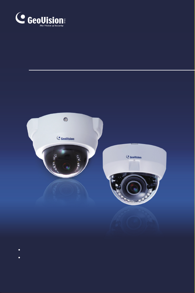
GV-IPCam H.264
Hardware Manual
Fixed IP Dome
Target Fixed Dome
Before attempting to connect or operate this product,
please read these instructions carefully and save this manual for future use.
ICH264TG2V10
Page 2

© 2015 GeoVision, Inc. All rights reserved.
Under the copyright laws, this manual may not be copied, in whole or in
part, without the written consent of GeoVision.
Every effort has been made to ensure that the information in this manual is
accurate. GeoVision, Inc. makes no expressed or implied warranty of any
kind and assumes no responsibility for errors or omissions. No liability is
assumed for incidental or consequential damages arising from the use of
the information or products contained herein. Features and specifications
are subject to change without notice. Note: no memory card slot or local
storage function for Argentina.
GeoVision, Inc.
9F, No. 246, Sec. 1, Neihu Rd.,
Neihu District, Taipei, Taiwan
Tel: +886-2-8797-8377
Fax: +886-2-8797-8335
http://www.geovision.com.tw
Trademarks used in this manual: GeoVision, the GeoVision logo and GV
series products are trademarks of GeoVision, Inc. Windows and Windows
XP are registered trademarks of Microsoft Corporation.
September 2015
Page 3

Contents
Contents ..............................................................................i
Options .............................................................................. iii
Note for Adjusting Focus and Zoom..............................
iv
Chapter 1 Fixed IP Dome .................................................1
1.1 Packing List..............................................................................3
1.1.1 Packing List for Hard-Ceiling Mount.............................3
1.1.2 Packing List for In-Ceiling Mount..................................4
1.2 Features...................................................................................5
1.3 Overview ..................................................................................7
1.4 Installation................................................................................9
1.4.1 Hard-Ceiling Mount......................................................9
1.4.2 In-Ceiling Mount.........................................................
1.4.3 Wall-Surface Mount ...................................................17
1.5 Connecting the Camera..........................................................19
1.6 I/O Terminal Block..................................................................
1.6.1 Pin Assignment..........................................................
1.6.2 Voltage Load Expansion (Optional)............................
1.7 Loading Factory Default..........................................................
Chapter 2 Target Fixed Dome........................................
13
20
20
21
22
23
2.1 Packing List............................................................................
24
i
Page 4

2.2 Features................................................................................. 25
2.3 Overview ................................................................................27
2.4 Installation..............................................................................29
2.5 Connecting the Camera..........................................................
2.6 Loading Factory Default..........................................................
32
33
ii
Page 5
Options
Optional devices can expand your camera’s capabilities and versatility.
Contact your dealer for more information.
Device Description
The power adapter is available for all Fixed IP Dome
Power Adapter
GV-PA191 PoE
Adapter
GV-POE Switch
GV-Mount
Accessories
GV-Relay V2
Smoked Cover
Camera. Contact your sales representative for the
countries and areas supported.
The GV-PA191 PoE adapter is designed to provide
power and network connection to the cameras over
a single Ethernet cable.
The GV-POE Switch is designed to provide power
along with network connection for IP devices. The
GV-POE Switch is available in various models with
different numbers and types of ports.
The GV-Mount Accessories provide a
comprehensive lineup of accessories for installation
on ceiling, wall corner and pole. For details, see GV-
Mount Accessories Installation Guide on the
Software DVD.
The GV-Relay V2 is designed to expand the voltage
load of GV IP devices. It provides 4 relay outputs,
and each can be set as normally open (NO) or
normally closed (NC) independently as per your
requirement.
The smoked cover is an IK7, tinted camera cover
designed for GV-Fixed IP Dome to conceal the
direction of the camera lens.
iii
Page 6
Note for Adjusting Focus and Zoom
When adjusting the Focus and Zoom Screws, do not over tighten the
Focus and Zoom screws. The screws only need to be as tight as your
finger can do it. It is not necessary to use any tools to get them tighter.
Doing so can damage the structure of lens.
For example,
Focus Screw
Zoom Screw
Fixed IP Camera
The maximum torque value for all the zoom and focus screws is 0.049 N.m
iv
Page 7
Fixed IP Camera
1
Chapter 1 Fixed IP Dome
The Fixed IP Dome is a series of indoor camera designed with 3-axis
mechanism for easy and flexible installation. The Fixed IP Dome features
IR LED for infrared illumination for night surveillance. The WDR Pro
models can produce clear image for scenes containing contrasting intensity
of lights. T he motorized varifocal lens models allow the user to remotely
adjust the zoom and focus through the Web interface. The super low lux
models are able to display color live view in near darkness. For related
models, see 1.2 Features. The models are detailed below:
Model No. Specification Description
GV-FD220D
GV-FD320D
GV-FD1200
GV-FD1500
GV-FD2400
GV-FD2500
GV-FD3400
Varifocal
Lens
Auto Iris, f:3 ~ 9
mm, F/1.3, 1/3”
ø 14 mm lens mount
Auto Iris, f: 3 ~ 9
mm, F/1.2, 1/2.7’’
ø 14 mm Mount
1.3 MP Low Lux / 2
MP / 3 MP, H.264,
D/N, Fixed IP Dome
1.3 MP Low Lux,
H.264, D/N, Fixed IP
Dome
1.3 MP Super Low
Lux / 2 MP WDR Pro
/ 2 MP Super Low
Lux / 3 MP WDR
Pro, H.264, D/N,
1
Page 8
Model No. Specification Description
1.3 MP Low Lux,
GV-FD1210
H.264, D/N, 3x
Optical Zoom, Fixed
IP Dome
Motorized
GV-FD1510
GV-FD2510
GV-FD2410
GV-FD3410
Models with P-Iris (Coming)
Model No. Specification Description
GV-FD1500
GV-FD2500
GV-VD3400
GV-FD1510
GV-FD2510
GV-FD3410
varifocal
Lens
Varifocal
Lens
Motorized
varifocal
Lens
Auto Iris, f: 3 ~ 9
mm, F/1.2, 1/2.7’’
ø 14 mm Mount
P-Iris, f: 3 ~ 9 mm,
F/1.2, 1/2.7’’
ø 14 mm Mount
1.3 MP / 2 MP Super
Low Lux, H.264,
D/N, 3x Optical
Zoom, Fixed IP
Dome
2 MP / 3 MP, H.264,
D/N, WDR Pro, 3x
Optical Zoom, Fixed
IP Dome
1.3 MP Super Low
Lux / 2 MP Super
Low Lux / 3 MP
WDR Pro, H.264,
D/N, Fixed IP Dome
2
Page 9
1
1.1 Packing List
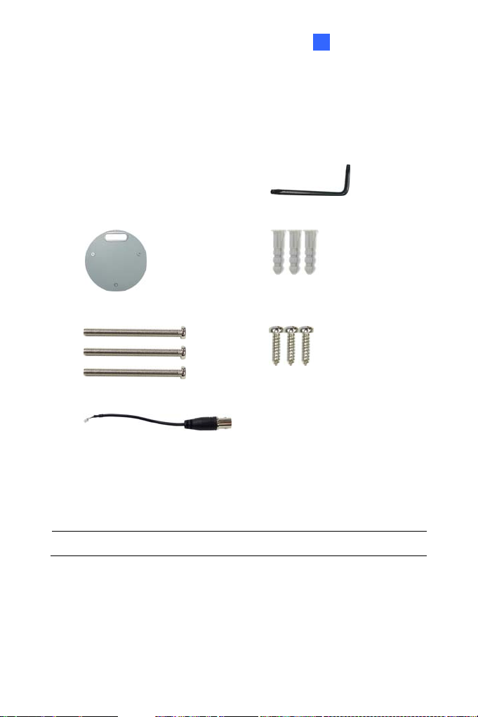
1.1.1 Packing List for Hard-Ceiling Mount
Fixed IP Camera
Fixed IP Dome
Mounting Plate
Ceiling Screw x 3
TV-out Wire
Power Adapter GV-IPCAM H.264 Software
GV-NVR Software DVD Warranty Card
Torx Wrench
Short Screw Anchor x 3
Plate Screw x 3
Sticker
DVD
Note: The power adapter can be excluded upon request.
3
Page 10
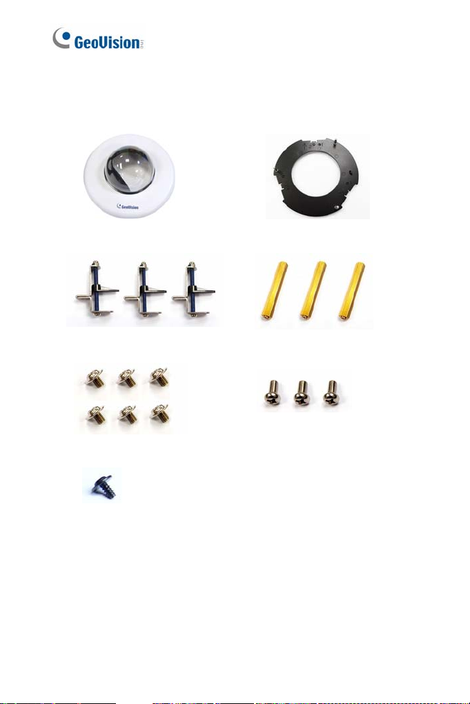
1.1.2 Packing List for In-Ceiling Mount
In-Ceiling Housing Cover
Mounting Bracket x 3
Copper Pillar Screw x 6
Thread Lock Screw
Mounting Plate
Copper Pillar x 3
Bracket Screw x 3
Housing Cover Thread
Sticker (In-Ceiling Mount)
4
Page 11
Fixed IP Camera
1
1.2 Features
Image sensor
Camera Model Image Sensor
GV-FD1200 / 1210 1/3’’ progressive scan low lux CMOS
GV-FD1500 / 1510 1/3’’ progressive scan super low lux CMOS
GV-FD2500 / 2510
GV-FD2400 / 2410
GV-FD3400 / 3410
GV-FD220D
GV-FD320D
Dual streams from H.264 or MJPEG
Frame rate
Camera Model Frame Rate
GV-FD1200 / 1210
GV-FD1500 / 1510
GV-FD220D
GV-FD2400 / 2410
GV-FD2500 / 2510
GV-FD320D
GV-FD3400 / 3410
Day and night function (with removable IR-cut filter)
P-Iris for auto iris adjustment (Coming, for GV-FD1500 / 1510 / 2500 /
2510 / 3400 / 3410 only)
Wide Dynamic Range Pro (for GV-FD2400 / 2410 / 3400 / 3410 only)
Defog
3-axis mechanism (pan / tilt / roll)
Built-in IR LED
1/2.8’’ progressive scan super low lux
CMOS
1/3.2’’ progressive scan CMOS
1/2.5’’ progressive scan CMOS
30 fps at 1280 x 1024
30 fps at 1920 x 1080
20 fps at 2048 x 1536
5
Page 12

Micro SD card slot (SD/SDHC) for local storage
NAS recording
Recording assigned by GV-Edge Recording Manager (Windows &
Mac)
One sensor input and alarm output
TV-out support
Two-way audio
3D noise reduction (for GV-FD1500 / 1510 / 2500 / 2510)
2D noise reduction (except for GV-FD1500 / 1510 / 2500 / 2510)
Motion detection
Tampering alarm
Visual automation
Text overlay
Privacy mask
IP address filtering
DC 12V / AC 24V / PoE (IEEE 802.3af)
Megapixel lens
Support for iPhone, iPad, Android and 3GPP
31 languages on Web interface
ONVIF (Profile S) conformant
6
Page 13

1.3 Overview
1
2
3
4
5
Fixed IP Camera
1
6 7 8 9
10
11 12 13
Figure 1-1
14 15
No. Name Description
1 Focus Screw Adjusts the focus of the camera.
2 Zoom Screw Adjus ts the zoom of the camera.
3 Rotational Screw Loosens to adjust the camera angle.
4 Tilt Screw Loosens the screw to tilt the camera.
5 Pan Disc Loosens to pan the camera.
Connects to a portable monitor for setting
6 Video Out
7 Memory Card Slot
8 Default Button
the focus and angle of Fixed IP Dome
during initial installation.
Inserts a micro SD ca r d (SD/SDHC,
version 2.0, Class 10) to store recording
data.
Restores the camera to factory default.
For details, see 1.7 Loading Factory
Default.
7
Page 14

No. Name Description
9 Audio In Connects a microphone for audio input.
10 Audio Out Connects a speaker for audio output.
11 LAN / PoE Connects to a 10/100 Ethernet or PoE.
12 I/O Terminal Block
13 DC 12V Port Connects to power.
14 Status LED
15 Power LED
Connects to I/O devices. For details, see
1.6 I/O Terminal Block.
Turns on (green) when the system
operates normally and turns off when
system error occurs.
Turns on (green) when the power is on
and turns off when there is no power
supply.
8
Page 15

Fixed IP Camera
1
1.4 Installation
The Fixed IP Dome is designed for indoors. With the standard packing,
there are three ways to install the Fixed IP Dome: hard-ceiling mount, in-
ceiling mount and wall-surface mount.
Note: You may also install the camera to ceilings, wall corners
(concave or convex), and poles with optional mounting kits. For details,
see GV-Mount Accessories Installation Guide on the Software CD.
1.4.1 Hard-Ceiling Mount
Figure 1-2
1. Paste the supplied sticker onto a desired location on the ceiling. Drill
the three red dots and the ellipse mark only if you wish to run the
wires into the ceiling.
9
Page 16

2. Unpack the camera package and take out the camera body.
A. Use the torx wrench to loosen the housing cover at the front and
the back.
Figure 1-3
B. Take out the camera body
Figure 1-4
3. Secure the camera body to the mounting plate with three ceiling
screws.
Figure 1-5
10
Page 17

Fixed IP Camera
1
Connect the network, power and other cables to the camera. See 1.5
4.
Connecting the Camera.
5. Access the live view. See 2.1 Accessing the Live View, GV-IPCam
H.264 Firmware Manual.
6. Based on the live view, adjust the camera to a desired angle as
illustrated below.
Tip: The 3-axis mechanism offers flexible and easy ceiling / wall
installation.
Pan Adjustment
Figure 1-6
Tilt Adjustmen t
Figure 1-7
11
Page 18

Rotational Adjustment
7. Adjust image clarity using the GV-IP Device Uti lit y program. For
details, see 2.2 Adjusting Image Clarity, GV-IPCam H.264 Firmware
Manual.
8. Secure the housing cover as shown in step 2. Remove the indicated
part when necessary.
Figure 1-8
Figure 1-9
Note: Adjust the black mask inside the housing cover to make sure the
camera view is not obscured.
12
Page 19

Fixed IP Camera
1
1.4.2 In-Ceiling Mount
Figure 1-10
1. Follow step 2 in the 1.4.1 Hard-Ceiling Mount to remove the housing
cover and take out the camera body.
2. Paste the supplied sticker onto a desired location on the ceiling and
cut a circle on the ceiling along the edge of the sticker.
3. On the mounting plate, locate the 3 holes labeled as 1 and insert the
3 copper pillars from the back side.
Figure 1-11
13
Page 20

4. From the side with the numbering, secure the copper pillars with 3
copper pillar screws.
Figure 1-12
5. Place the 3 mounting brackets at the indent next to the copper pillars
(labeled as 2 on the mounting plate) and secure them using the 3
bracket scre ws.
Figure 1-13
14
Page 21

Fixed IP Camera
1
6.
Place the mounting plate on the camera body with the copper pillars
inserted in the locations indicated below. The arrow on the mounting
plate should be pointing toward the front of the camera.
Figure 1-14
7. From the bottom of the camera, secure the copper pillars using the 3
copper pillars screws.
8. Place the camera into the ceiling opening.
9. On the back side, make sure the black plastic clips are slightly above
the ceiling board and pointing outward.
Back Side Front Side
Figure 1-15
10. Tighten the bracket screws from the front side of the camera.
15
Page 22

11. Connect the network, power and other cables to the camera. See 1.5
Connecting the Camera.
12. Access the live view. See 2.1 Accessing the Live View, GV-IPCam
H.264 Firmware Manual.
13. Follow steps 6 and 7 in 1.4.1 Hard-Ceiling Mount section to adjust the
angle, focus and zoom of the camera.
14. Use the housing cover thread and the thread lock screw to attach the
housing cover to the camera body.
Figure 1-16
15. Place the housing cover on the camera body with the GeoVision logo
pointing toward the front of the camera.
16
Figure 1-17
Page 23

1.4.3 Wall-Surface Mount
Fixed IP Camera
1
1. Follow step 2 in 1.4.1 Hard-Ceiling Mount section to remove the
2. Paste the supplied sticker onto a desired location on the wall. Drill the
3. Insert the short screw anchors and secure the camera and the
Figure 1-18
housing cover and take out the camera body.
three red dots, and the ellipse mark only if you wish to run the wires
into the wall.
mounting plate with three plate screws.
Figure 1-19
4. Connect the network, power and other cables to the camera. See 1.5
Connecting the Camera.
17
Page 24

5. Access the live view. See 2.1 Accessing the Live View, GV-IPCam
H.264 Firmware Manual.
6. Follow steps 6 and 7 in 1.4.1 Hard-Ceiling Mount section to adjust the
angle, focus and zoom of the camera.
7. Follow step 8 in 1.4.1 Hard-Ceiling Mount section to secure the
housing cover.
18
Page 25

Fixed IP Camera
1
1.5 Connecting the Camera
Figure 1-20
1. Use a standard network cable to connect the camera to your network.
2. Optionally connect a speaker and an external microphone.
3. Optionally connect a monitor using a Video Out wire. Enable this
function by selecting your signal format at the TV Out field on the
Web interface. See 4.1.1 Video Settings, GV-IPCam H.264 Firmware
Manual.
4. Optionally connect to input / output devices. For details, see 1.6 I/O
Terminal Block.
5. Connect power using one of the following methods:
pl uggi ng the power adapter to power port.
using the Power over Ethernet (PoE) function and the power will
be provided over the network cable.
6. The status LED of the camera will be on.
19
Page 26

1.6 I/O Terminal Block
The terminal block, located on the back panel of the Fixed IP Dome,
provides the interface to one input and one output devices. The I/O
terminal block can be used for applications such as motion detection, event
alerts via E-Mail and FTP, and center monitoring through Center V2 and
VSM.
1.6.1 Pin Assignment
The Fixed IP Dome supports one digital input and one digital output of dry
contact.
I/O
123
Figure 1-21
Pin Function
1 Digital Output
2 GND
3 Digital Input
20
Page 27

Fixed IP Camera
1
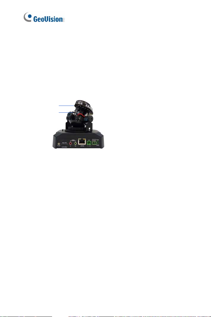
1.6.2 Voltage Load Expansion (Optional)
The camera on its own can only drive a maximum load of 200mA 5V DC.
To expand the maximum voltage load to 10A 250V AC / 10A 125V AC /
5A 100V DC), connect the camera to a GV-Relay V2 module (optional
product). Refer to the figure and table below:
Output Device
I/O
2
1
3
Connect to Power
Figure 1-22
GV-Relay V2 Bullet Camera
COM Pin 2 (GND)
DO1 Pin 1 (Digital Output)
21
Page 28

1.7 Loading Factory Default
1. Keep the power and network cables (or PoE) connected to the camera.
2. Use a pin to press and hold the default button on the panel.
Default button
3. Release the default button when the status LED blinks. This shall
take about 8 seconds.
4. When the status LED fades, the process of loading default settings is
completed and the camera reboots automatically.
22
Figure 1-23
Status LED
Page 29

Target Fixed Dome
2
Chapter 2 Target Fixed Dome
The Target Fixed Dome (GV-EFD) is an indoor, fixed network camera
equipped with an automatic IR-cut filter and IR LEDs for day and night
surveillance. Adjustable in 3 axis (pan, tilt and rotate), it offers an entrylevel surveillance solution with all the essential features and excellent
image quality.
Model No. Specifications Description
GV-EFD2101
GV-EFD3101
Varifocal
Lens
Varifocal
Lens
Fixed Iris, f: 3 ~ 9
mm, F/1.7, 1/2.8”
Ø14 mm Mount
Fixed Iris, f: 3 ~ 9
mm, F/1.7, 1/2.8”
Ø14 mm Mount
2 MP, H.264,
Super Low
Lux, WDR
3 MP, H.264,
Super Low
Lux, WDR Pro
23
Page 30

2.1 Packing List
Target Fixed IP Dome
Torx Wrench
Screw x 3
TV-Out Wire
GV-IPCam H.264 Software DVD Warranty Card
GV-NVR Software DVD
Screw Anchor x 3
Installation sticker
Note: Power adapter can be purchased upon request.
24
Page 31

Target Fixed Dome
2
2.2 Features
1/2.8” progressive scan super low lux CMOS
Frame rate:
Camera Model Frame Rate
GV-EFD2101 Up to 30 fps at 1920 x 1080
GV-EFD3101 Up to 30 fps at 2048 x 1536
Dual streams from H.264 or MJPEG
Intelligent IR
Day and night function (with removable IR-cut filter)
Megapixel lens
P-Iris lens for auto Iris control
Intelligent IR
3-axis mechanism (pan / tilt / rotate)
DV 12V / PoE (IEEE 802.3af)
Two-way audio
Wide Dynamic Range (WDR) for EFD2101;
Wide Dynamic Range (WDR) Pro for GV-EFD3101
Defog
Motion detection
Tampering alarm
Text overlay
Privacy mask
IP address filtering
NAS Recording
Recording assigned by GV-Edge Recording Manager (Windows &
Mac)
Support for iPhone, iPad, Android and 3GPP
31 languages on Web interface
25
Page 32

ONVIF (Profile S) conformant
Note: For optimal performance and compatibility, it is highly
recommended to use a GV-NAS System.
26
Page 33

Target Fixed Dome
2
2.3 Overview
Figure 2-2
No. Name Description
1 Lens Receives image inputs.
2 Focus Screw Adjusts the focus of the camera.
3 Zoom Screw Adjusts the zoom of the c amera.
Default
4
Button
5 TV-Out Provides video inputs (D1 resolution).
Rotational
6
Screw
7 Pan Disc Loosens to pan the camera.
8 Power Turns on (green) when power is on.
9 Status Turns on (green) when the system is ready.
10 Audio Out Connects a speaker for audio output.
11 Audio In Connects a microphone for audio input.
Resets the camera to factory default. For details,
see 2.6 Loading Factory Default.
Loosens to adjust the camera angle.
27
Page 34

No. Name Description
12 Link Turns on (green) when the network is connected.
13 ACT Turns on (orange) when data are being transmitted.
14 DC 12V Port Connects to power.
15 LAN / PoE Connects to a 10/100 Ethernet or PoE.
16 Tilt Screw Loosens the screw to adjust til t angle.
Note: The TV-out function can only be used during installation to adjust
the focus of the camera. To use the TV out function, connect the
supplied black BNC connector to a monitor and select your signal format
(NTSC or PAL) at the TV Out field on the Web interface. The default
signal format is NTSC. For details, see 4.1.1 Video Settings, GV-IPCam
H.264 Firmware Manual. The TV-out wire must be removed before you
secure the housing cover.
28
Page 35

Target Fixed Dome
2
2.4 Installation
The Target Fixed Dome can be installed on the wall or the ceiling. Before
installing the camera, make sure the installing site is shielded from rain and
moisture.
1. Use the supplied torx wrench to loosen three screws on the housing
cover, and take out the camera body.
Figure 2-3
29
Page 36

2. Place the installation sticker where you want to install it, and make 3
marks on the ceiling or the wall for screw anchors.
Figure 2-4
3. Drill the marks and insert the screw anchors.
4. Connect the camera to network and power. For details, see 2.5
Connecting the Camera.
5. Secure the camera to the ceiling or the wall with the supplied screws.
6. Access the live view. For details, see 2.1 Accessing the Live View,
GV-IPCam H.264 Firmware Manual.
Note: The TV-out function can only be used during installation to adjust
the focus of the camera. To use the TV out function, connect the
supplied black BNC connector to a monitor and select your signal format
(NTSC or PAL) at the TV Out field on the Web interface. The default
signal format is NTSC. For details, see 4.1.1 Video Settings, GV-IPCam
H.264 Firmware Manual. The TV-out wire must be removed before you
secure the housing cover.
7. Adjust image clarity using the GV-IP Device Uti lit y program. For
details, see 2.2 Adjusting Image Clarity, GV-IPCam H.264 Fi rmware
Manual.
30
Page 37

Target Fixed Dome
2
Loosen the tile screw, pan screw or rotational screw. Adjust the
8.
angles based on the live view as needed, and tighten the screws
again.
Figure 2-6
9. Place the housing cover back and tighten the three screws to secure
it. Remove the indicated part when necessary.
Figure 2-7
31
Page 38

2.5 Connecting the Camera
2
Figure 2-8
1. Connect power using one of the following methods:
1
P l ug the power adapter to the 12V terminal block. The power
adapter is an optional device. For detail, see Options in the
manual.
Use the Power over Ethernet (PoE) function and the power will be
provided over the network cable.
The power and status LEDs shall turn on (green).
2. Use a standard network cable to connect the camera to your network.
3. You are ready to access the live view, adjust the image clarity and
configure the basics. See Getting Started, Chapter 2, GV-IPCam
H.264 Firmware Manual.
32
Page 39

Target Fixed Dome
2
2.6 Loading Factory Default
1. Keep the power and network cables (or PoE) connected to the
camera.
2. Press and hold the default button for about 8 seconds.
Figure 2-9
3. Release the default button when the status LED blinks.
Figure 2-10
When the status LED fades, the process of loading default settings is
completed and the camera reboots automatically
33
 Loading...