

Page 1
GV-EL124S Electric Strike
Featured with a built-in door status sensor, the GV-EL124S is a fail-secure electric strike, but
it is field convertible from fail secure to fail safe. It can be mounted either right or left
reversibly on the doorjamb, providing remote release of a locked door.
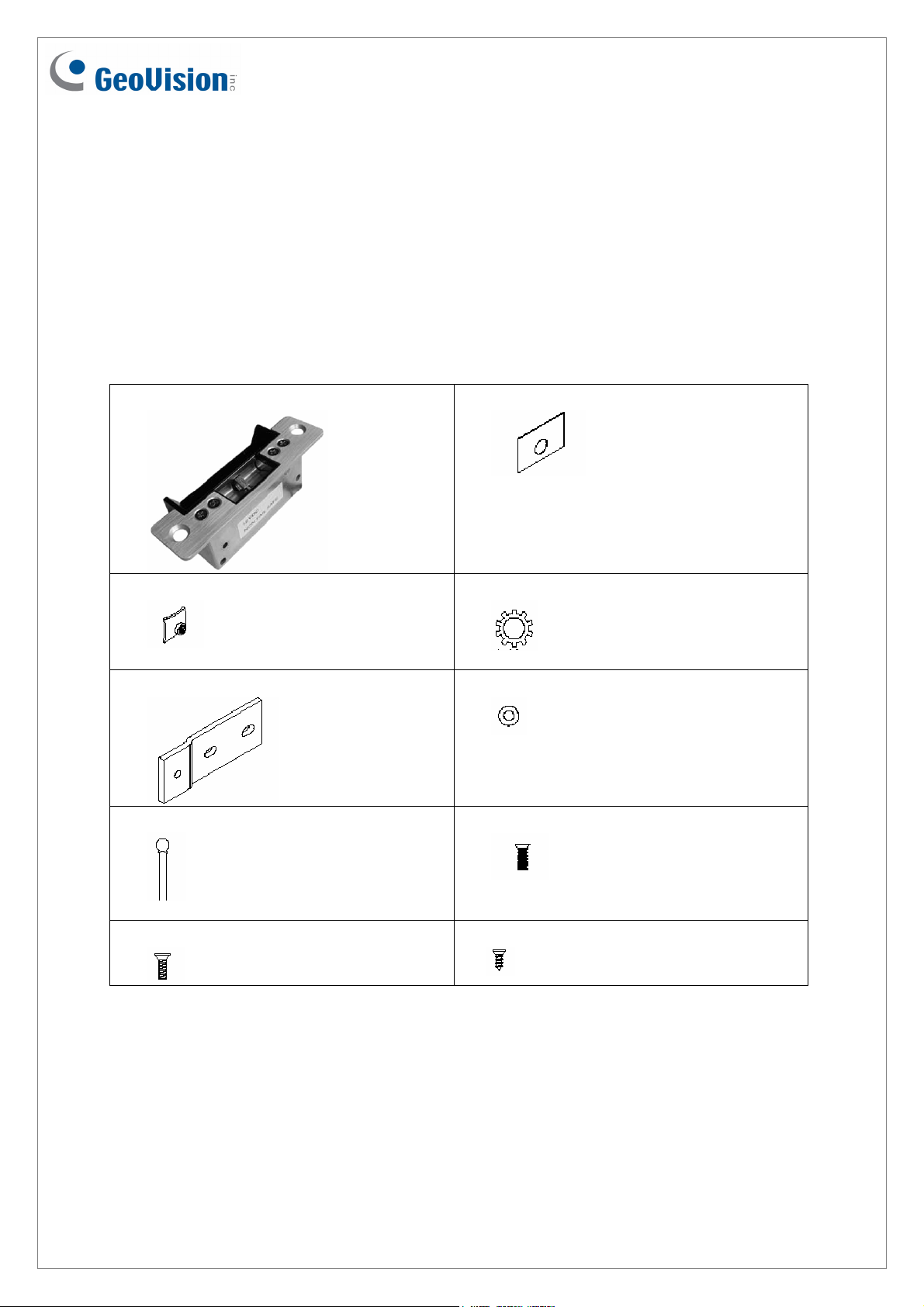
Packing List
1. GV-EL124S electric strike x 1
3. Clip nut x 2
5. Extension plate x 2
7. Varistor x 1
2. Aluminum spacer x 6
4. Lock washer x 2
6. Clip x 2
8. M4 screw x 2
9. #10-32 screw x 2
October 2, 2013
10. #8-32 flat-head screw x 2
1
Page 2
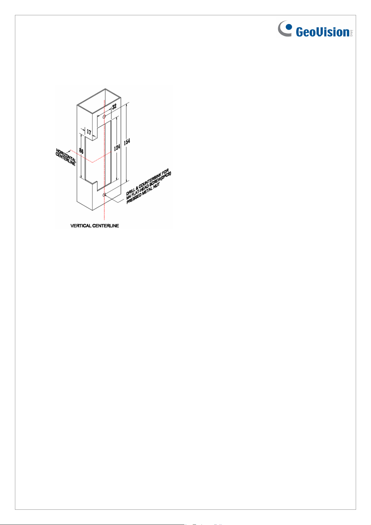
Installation
1. Prepare the doorjamb per drawing.
Figure 1
2. Install the mounting brackets to the doorjamb by using the #8-32 x 1/2” flat-head screws
and the pressed metal nuts (Figure 2). Do not tighten yet.
2
October 2, 2013
Page 3

3. Spacers are provided to ensure the final assembly of faceplate into the doorjamb. Add
one of spacers between the doorjamb and the mounting bracket when faceplate extends
beyond the doorjamb. When the faceplate sets inside the jamb, spacers must be added
between the mounting bracket and the tip bracket. Make sure the clearance hole in the
spacer aligns with the hole in the mounting bracket.
Figure 2
4. Connect the wires from the low voltage side of the transformer to the black wires of the
electric strike.
Figure 3
October 2, 2013
3
Page 4

5. Install the electric strike to the doorjamb by using the #10-32 screws and the lock
washers (Figure 2).
6. Tighten the #8-32 flat-head screws to hold the mounting brackets to the doorjamb (Figure
2).
7. To prevent strike from spike, connect the Varistor between the input power wires (Figure
3).
8. To modify fail-safe to non fail-safe or vice versa.
A. Unscrew the electric strike as illustrated below.
B. Reverse the solenoid to the opposite side and then close.
Figure 4
Wire Definition
Wire Definition
Black Positive (+) or Ground (-)
Electric Bolt
Black Positive (+) or Ground (-)
Green NO
Lock Status Sensor
Door Status Sensor
Grey COM
Orange NC
Blue NO
White COM
Yellow NC
4
October 2, 2013
Page 5

Connecting to the GV-AS Controller
To connect the electric strike to the GV-AS Controller, follow the steps below. Here we use
the GV-AS400 Controller for example.
1. To connect the power between the electric strike and the GV-AS400, refer to the diagram
as below.
External
Power
GV-AS400 Output
Supply
+
NO
NC
COM
_
Electric Strike
Two Black Wires
Figure 5
Connect one black wire of the electric strike to COM on GV-AS400, connect the other
black wire of the electric strike to the (-) point on the external power supply, and connect
the (+) point on the external power supply to NO on GV-AS400.
2. To connect the sensor to the GV-AS400, connect the Yellow wire of the sensor to the
Input of the GV-AS400, and connect the White wire of the sensor to the Ground of the
GV-AS400.
Yellow
White
GV-AS400 Input
Electric Strike
Figure 6
October 2, 2013
5
Page 6

3. On the Web interface of the GV-AS400, select Input Setting, and select an input type
and input function for the connected sensor from the electric strike.
Figure 7
4. On the Web interface of the GV-AS400, select Output Setting, and select an output type
and output function for the connected electric strike.
Output Type Output Function
Figure 8
For details on configuring the input and out devices, see 3.4.3.D Input Function and 3.4.3.E
Output Function on the GV-AS Controller User’s Manual.
Specifications
Voltage
Current
Keeper Depth
Temperature Resistance
DC 12V (default) or DC 24V
260mA at DC 12V or 150mA at DC 24V
12.7 mm (0.50”)
-30°C ~ 80°C (20 °F ~ 160 °F)
Dimensions (L x W x H)
Weight
Certification
123.5 x 31.4 x 40.7 mm (4.86” x 1.24” x 1.60”)
400 g (0.88 lb)
CE
6
October 2, 2013
 Loading...