

Page 1
GV-APOE1611 16-Port Gigabit 802.3at Web Management
PoE Switch
Packing List
1. GV-APOE1611 x 1
2. Power Cord x 1
3. Screw x 8
4. Rack Mount Kit
5. Rubber Feet x 4
Note: If any of these items is found missing or damaged, please contact your local supplier
for replacement.
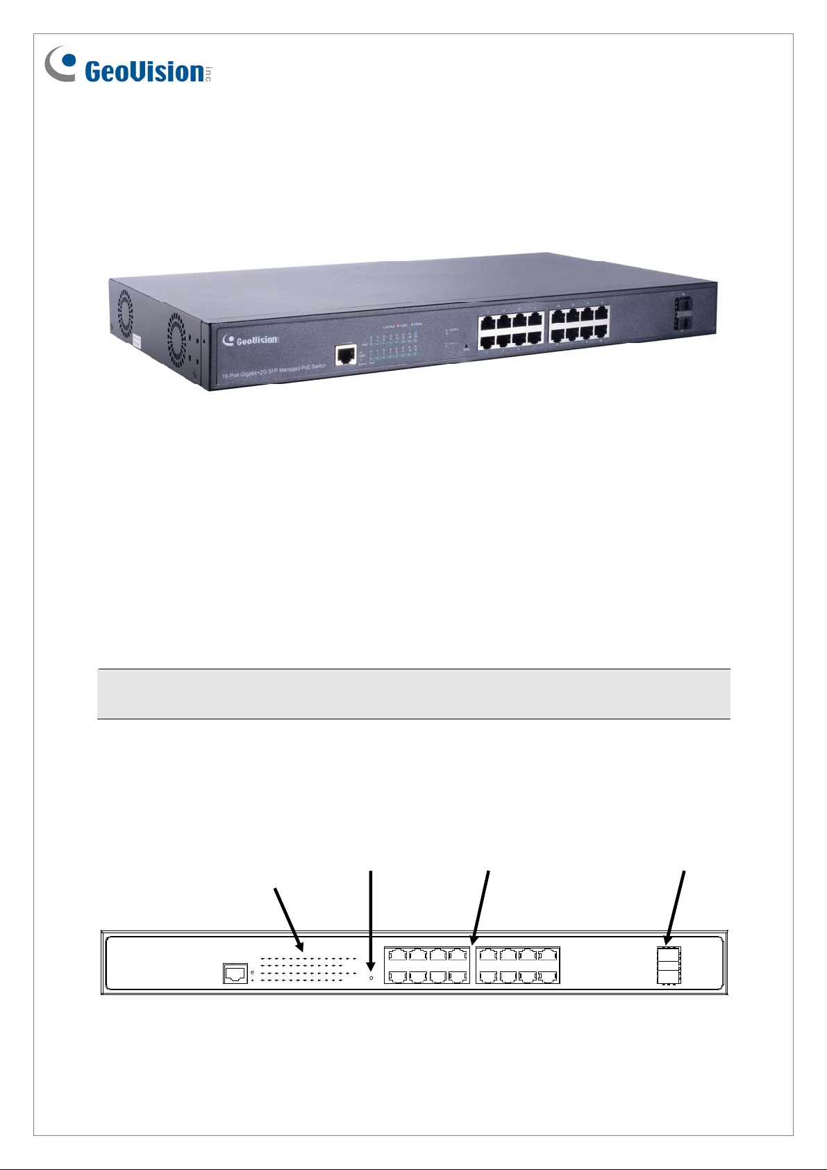
Front Panel
LED
Display
Reset
Button
Gigabit
RJ-45
Gigabit
SFP
April 14, 2020
1
Page 2
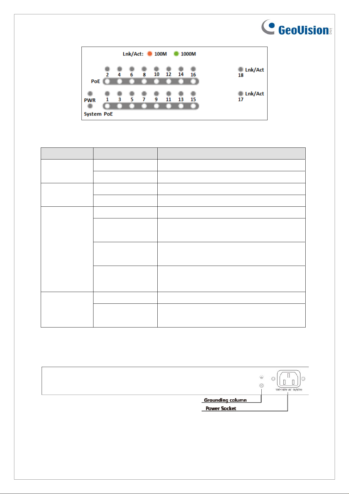
LED Indicators on the switch
LED Color/Status Description
System
LINK/ACT
PWR
PoE
Off No power supply
Green System powered on
Off System is starting or has no power
Blinking Green System is working
Off No devices connected to the corresponding port
Red
Green
Blinking Red / Green
Off No PoE powered devices (PD) connected
Orange
Network through the corresponding port has been
successfully established at 10/100 Mbps.
Network through the corresponding port has been
successfully established at 1000 Mbps.
Data currently being sent through the
corresponding port at 10/100 (orange) or 1000
(green) Mbps
At least one device successfully powered through
PoE
Rear Panel
2
April 14, 2020
Page 3

Mount Installation
Desktop
Rack
April 14, 2020
3
Page 4

Connecting up to 16 GV-IP Cameras and 1 GV-NVR / DVR / VMS
System
Through twisted pair cables, this switch can be connected to up to 16 GV-IP Cameras and 1
GV-NVR / DVR / VMS System. You can also extend the connections by connecting to other
switches.
GV-IP Camera x 16
Switch
GV-NVR/ DVR / VMS System
Note:
1. GV-NVR / DVR / VMS or a switch can connect to either RJ-45 ports or SFP ports.
2. The maximum cable length for:
Gigabit RJ-45 (Cat.5) is 100 meters.
Gigabit RJ-45 (Cat.5e, 6) can achieve 250 meters by setting the network bandwidth
of the 16 PoE ports to 10 Mbps per port on the device’s Web interface. See details in
Figure 16, 2.3.1 Port Setting, GV-PoE Switch User’s Manual.
3. For connection that exceeds 250 meters, you can use the Gigabit SFP ports.
4
April 14, 2020
Page 5

Accessing Web Interface
Users can log in the Web interface to manage and set up the switch. Follow the below steps
to log in the Web interface.
1. To access the Web user interface, type the default IP 192.168.0.250 into your Web
browser. The login page appears.
2. Type the default username admin and password admin. Click Login In.
3. When prompted to create your login credentials, type the necessary information and click
Apply. The System Information window appears.
4. To configure the GV-PoE Switch, select desired functions from the left menu.
Loading Default Setting
You can load the default value with the Reset button or with the Web interface.
Hardware
1. Turn on the switch.
2. Press and hold the Reset button on the front panel of the switch for 5 seconds until all
the LED start blinking.
3. Release the button. The switch is restored to its default settings.
April 14, 2020
5
Page 6
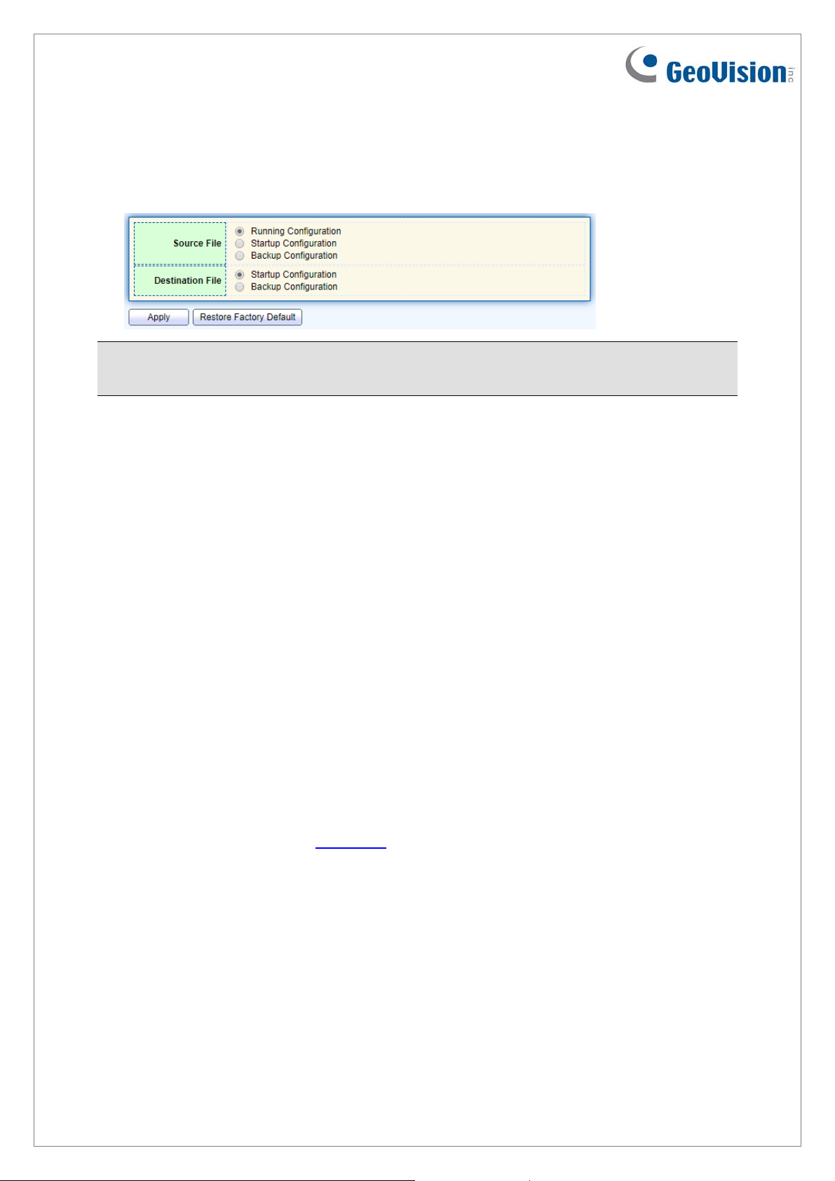
Web Interface
1. Management > Configuration > Save Configuration.
2. Click Restore Factory Default to restore the switch to the original configuration.
Note: After loading default by pressing the Reset button or from the Web interface, you will
need to configure IP address and Password again.
Updating Firmware
1. Management > Firmware > Upgrade/Backup.
2. Select Upgrade in the Action section.
3. Select TFTP or HTTP in the Method section.
If TFTP is selected, select Hostname / IPv4 / IPv6 in the Address Type section >
specify the TFTP server address.
If HTTP is selected, click Browse to select the firmw a re fil e .
4. Click Apply. The upgrade process is started.
5. After the firmware is successfully upgraded, click Logout from the left menu and re-login
the switch.
Specifications
For detailed specifications, see Datasheet
6
April 14, 2020
 Loading...