

Page 1
GV-IP Camera
User's Manual
GV-EBD Series
GV-ABLSeries
GV-ADR Series
GV-AVD Series
Before attempting to connect or operate this product,
please read these instructions carefully and save this manual for future use.
UBN-UM-D
Page 2

© 2018 GeoVision, Inc. All rights reserved.
Under the copyright laws, this manual may not be copied, in whole or in part,
without the written consent of GeoVision.
Every effort has been made to ensure that the information in this manual is
accurate. GeoVision, Inc. makes no expressed or implied warranty of any kind
and assumes no responsibility for errors or omissions. No liability is assumed
for incidental or consequential damages arising from the use of the information
or products contained herein. Features and specifications are subject to
change without notice.
Note: No memory card slot or local storage function for Argentina.
GeoVision,
9F, No. 246, Sec. 1, Neihu Rd.,
Neihu District, Taipei, Taiwan
Tel: +886-2-8797-8377
Fax: +886-2-8797-8335
http://www.geovision.com.tw
Trademarks used in this manual: GeoVision, the GeoVision logo and GV
series products
trademark of Microsoft Corporation.
August 2018
Inc.
are trademarks of GeoVision, Inc. Windows is the registered
Page 3
Preface
elcome to the GV-EBD Series IR Eyeball IP Dome, GV-ABL Series Bullet IP Camera and
W
GV-ADR Series Mini Fixed Rugged IP Dome, GV-AVD Series Vandal Proof IP Camera User’s
Manual.
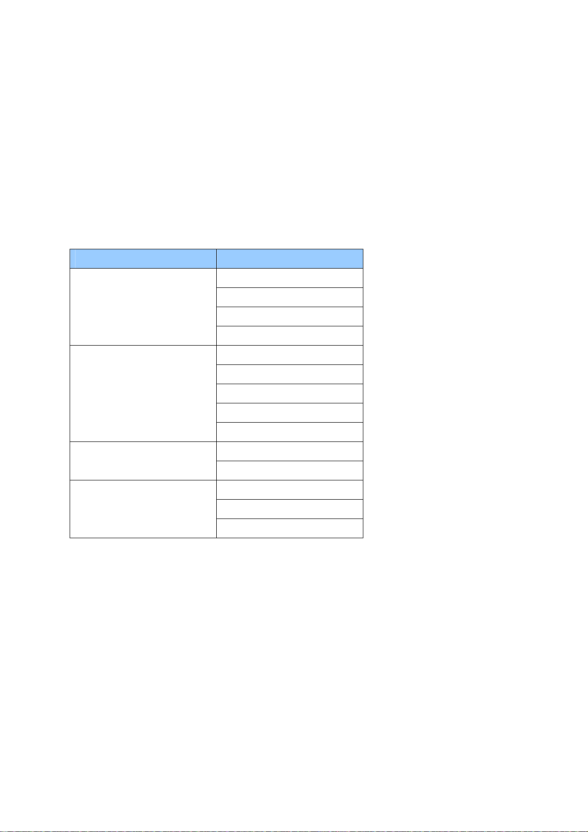
This Manual is designed for the following models:
Model Model Number
GV-EBD2702
IR Eyeball Dome
Bullet IP Camera
Mini Fixed Rugged IP Dome
Vandal Proof IP Dome
GV-EBD4700
GV-EBD4711
GV-EBD8711
GV-ABL2701 Series
GV-ABL2702
GV-ABL4701
GV-ABL4712
GV-ABL8712
GV-ADR2701
GV-ADR4701 Series
GV-AVD2700
GV-AVD4710
GV-AVD8710
i
Page 4

Contents
Naming Definition....................................................................vi
Note for Connecting to GV-VMS / DVR / NVR ......................vii
Note for Installing Camera Outdoor .....................................vii
Note for Powering the Camera ..............................................vii
Chapter 1 Introduction ..........................................................1
1.1 GV-EBD Series...................................................................................................... 1
1.1.1 Packing List................................................................................................ 2
1.1.2 Optional Accessories ................................................................................. 3
1.1.3 Overview.................................................................................................... 4
1.1.3.1 GV-EBD2702 / 4700 .................................................................. 4
1.1.3.2 GV-EBD4711 / 8711 .................................................................. 5
1.1.4 Installation.................................................................................................. 6
1.1.4.1 GV-EBD2702 / 4700 Standard Installation ................................. 6
1.1.4.2 GV-EBD4711 / 8711 Standard Installation ................................. 9
1.1.5 Optional Installation...................................................................................12
1.1.5.1 GV-Mount211P .........................................................................12
1.1.5.2 GV-Mount212P .........................................................................18
1.2 GV-ABL Series .....................................................................................................23
1.2.1 Packing List...............................................................................................24
1.2.2 Optional Accessories ................................................................................25
1.2.3 Overview...................................................................................................26
1.2.3.1 GV-ABL2701 Series / 4701 Series ............................................26
1.2.3.2 GV-ABL2702 / 4712 / 8712 .......................................................27
1.2.4 Installation.................................................................................................28
1.2.5 Optional Installation...................................................................................31
1.2.5.1 GV-Mount502............................................................................32
1.2.5.2 GV-Mount503............................................................................36
1.3 GV-ADR Series.....................................................................................................39
1.3.1 Packing List...............................................................................................40
1.3.2 Optional Accessories ................................................................................41
1.3.3 Overview...................................................................................................42
1.3.4 Installation.................................................................................................43
1.3.5 Optional Installation...................................................................................46
ii
Page 5

.1 GV-Mount211P .........................................................................46
1.3.5
1.3.5.2 GV-Mount213............................................................................46
1.4 GV-AVD Series.....................................................................................................50
1.4.1 Packing List...............................................................................................51
1.4.2 Optional Accessories ................................................................................52
1.4.3 Overview...................................................................................................53
1.4.4 Installation.................................................................................................54
1.4.5 Optional Installation...................................................................................56
1.4.5.1 GV-Mount211-2.........................................................................56
1.4.5.2 GV-Mount212-2.........................................................................59
1.5 System Requirements...........................................................................................62
1.6 Waterproofing the Cable .......................................................................................63
Chap
ter 2 Accessing the Camera.......................................65
2.1 Installing on a Network..........................................................................................65
2.1.1 Checking the Dynamic IP Address ............................................................66
2.1.2 Assigning an IP Address ...........................................................................68
2.2 Accessing Live View .............................................................................................69
2.2.1 The Live View Window..............................................................................70
2.3 Playing Back Recorded Videos.............................................................................73
2.3.1 The Playback Window...............................................................................74
Chapter 3 Administrator Mode ...........................................76
3.1 Common...............................................................................................................78
3.1.1 Basic Info ..................................................................................................78
3.1.2 Local Settings ...........................................................................................79
3.2 Network ................................................................................................................81
3.2.1 Ethernet ....................................................................................................81
3.2.2 DNS..........................................................................................................82
3.2.3 Port...........................................................................................................83
3.2.4 DDNS........................................................................................................84
3.2.5 E-mail........................................................................................................86
3.2.6 802.1x.......................................................................................................87
3.3 Video & Audio .......................................................................................................88
3.3.1 Video.........................................................................................................88
3.3.2 Snapshot...................................................................................................90
iii
Page 6

3.3.3 Audio.........................................................................................................91
3.3.4 ROI ...........................................................................................................92
3.3.5 Media Stream............................................................................................93
3.4 Image ...................................................................................................................95
3.4.1 Image........................................................................................................95
3.4.2 OSD........................................................................................................101
3.4.3 Privacy Mask...........................................................................................103
3.5 Events ................................................................................................................104
3.5.1 Motion Detection .....................................................................................104
3.5.2 Tampering Alarm ....................................................................................107
3.5.3 Audio Detection.......................................................................................108
3.5.4 Alarm Input..............................................................................................109
3.5.5 Alarm Output...........................................................................................110
3.6 Storage...............................................................................................................111
3.6.1 Storage ...................................................................................................111
3.6.2 FTP .......................................................................................................113
3.7 Security...............................................................................................................115
3.7.1 User ........................................................................................................115
3.7.2 Network Security.....................................................................................116
3.8 System................................................................................................................119
3.8.1 Time........................................................................................................119
3.8.2 Maintenance ...........................................................................................121
Chapter 4 Advanced Applications ...................................122
4.1 Upgrading System Firmware...............................................................................122
4.1.1 Using the Web Interface..........................................................................123
4.1.2 Using GV-IP Device Utility.......................................................................124
4.2 Restoring to Factory Default Settings..................................................................125
Chapter 5 DVR / NVR / VMS ..............................................126
5.1 Setting Up IP Cameras on GV-DVR / NVR .........................................................127
5.1.1 Customizing the Basic Settings on GV-DVR / NVR .................................129
5.2 Setting Up IP Cameras on GV-VMS ...................................................................130
iv
Page 7

Appendix ...............................................................................132
A. RTSP Multicast Protocol Support .......................................................................132
B. RTSP Protocol Support ........................................................................................133
C. HTTP Protocol Support ........................................................................................134
v
Page 8

Naming Definition
GV-DVR / NVR
GV-VMS
GeoVision Analog and Digital Video Recording Software. The GVDVR also refers to GV-Multicam System or GV-Hybrid DVR.
GeoVision Video Management System for IP cameras.
vi
Page 9
Note for Connecting to GV-VMS / DVR / NVR
The GV-IPCAM in this Manual is designed to work with and record on GV-VMS / DVR / NVR,
a video management system. Once the camera is connected to the GV-VMS / DVR / NVR,
the resolution set on the GV-VMS / DVR / NVR will override the resolution set on the
camera’s Web interface. You can only change the resolution settings through the Web
interface when the connection to the GV-VMS / DVR / NVR is interrupted.
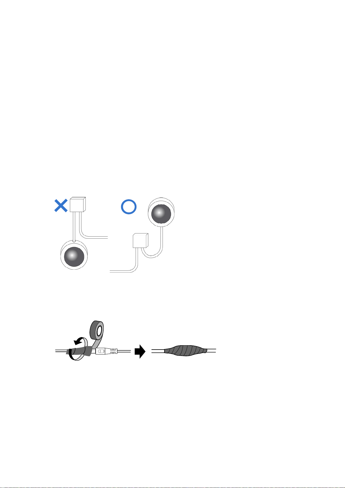
Note for Installing Camera Outdoor
When installing the camera outdoor, be sure that:
1. The camera is set up above the junction box to prevent water from entering the camera
along the cables.
2.
Any PoE, power, audio and I/O cables are waterproofed using waterproof silicon rubber
or the like
3. The screws are tightened and the cover is in place after opening the camera cover.
.
Note for Powering the Camera
The camera is powered by PoE or a power adapter. If you want to power the camera using
the power connector, an optional power adapter is required.
i
vi
Page 10

Chapter 1 Introduction
1.1 GV-EBD Series
The H.265 Target Eyeball Dome is an outdoor, network camera equipped with an automatic
IR-cut filter and IR LEDs for day and night surveillance. The camera adheres to IP67
standards for dust / water protection and supports H.265 video codec to achieve better
compression ratio while maintaining high quality image at reduced network bandwidths.
With its WDR Pro (WDR for GV-EBD2702), It can process scenes with contrasting intensity
of lights and produce clear image.
For GV-EBD4711 / 8711, with their motorized lenses, the user can zoom and focus the
camera from the Web interface. The camera also provides built-in micro SD card slot for
local storage.
Model No. Specifications Description
GV-EBD2702
GV-EBD4700
GV-EBD4711
GV-EBD8711
Fixed lens
Motorized
varifocal lens
Fixed Iris, f: 2.8 mm,
F/1.8, M12 Lens Mount
Fixed Iris, f: 2.7 ~ 12 mm,
F/1.4, Ø12 mm Lens
Mount
Fixed Iris, f: 2.8 ~ 12 mm
F/1.5, Ø12 mm Lens
Mount
2 MP, H.265,
Low Lux, WDR
4 MP, H.265,
Low Lux, WDR Pro
4 MP, H.265,
Low Lux, WDR Pro
8 MP, H.265,
Super Low Lux,
WDR Pro
1
Page 11
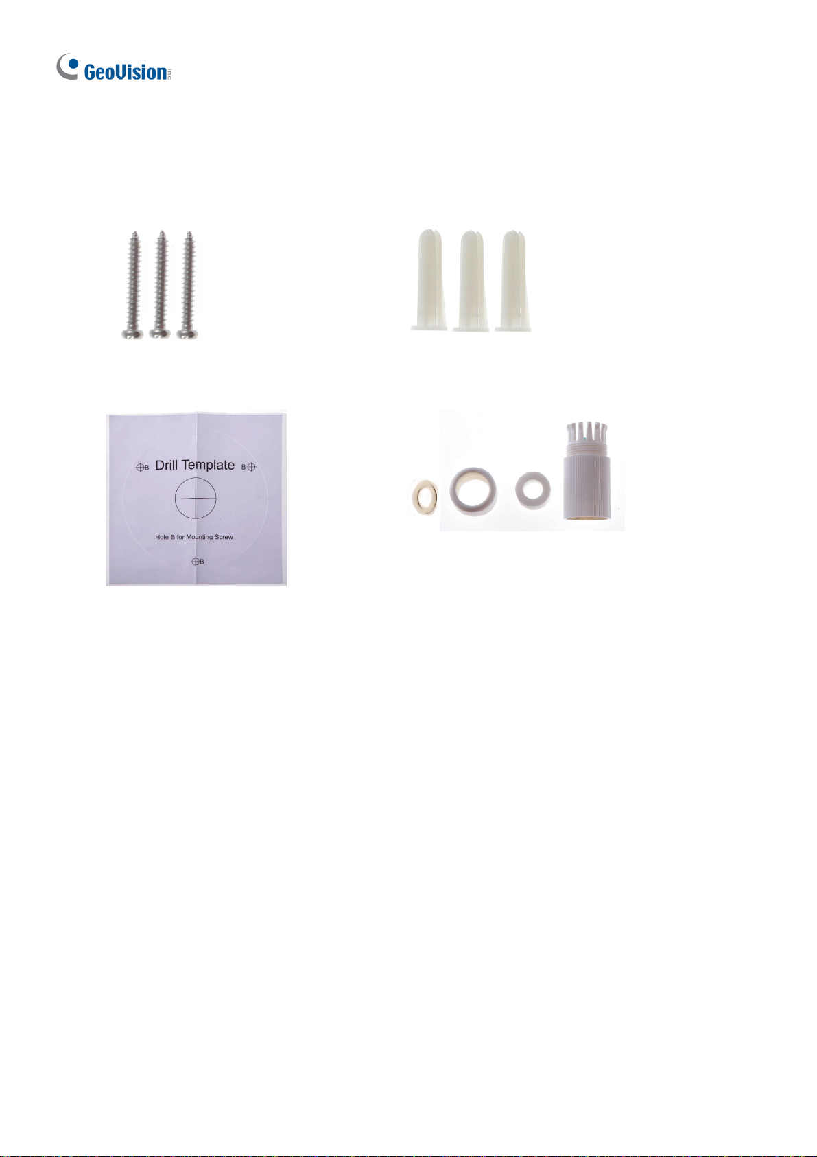
1.1.1 Packing List
H.265 Target Eyeball Dome
Screw x 3
Drill Template Paster
Screw Anchor x
Waterproof Rubber Set
3
Download Guide Warranty Card
2
Page 12
Introduction
1
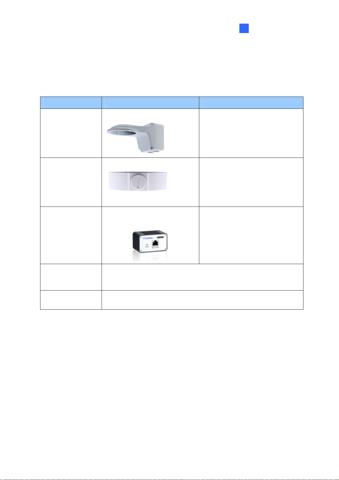
1.1.2 Optional Accessories
Optional accessories can expand the capabilities and versatility of your camera. Contact your
dealer for more information.
Model Number Name Details
GV-Mount211P Wall Mount Bracket
GV-Mount212P Wall Box Mount
GV-PA191
Power over Ethernet (PoE)
Adapter
GV-POE Switch
GV-POE Switch is designed to provide power along with network
connection for IP devices. GV-POE Switch is available in various
models with different numbers and types of ports.
Dimensions: 233 x 126 x 126 mm
(9.2” x 5” x 5”)
Weight: 1 kg (2.2 lb)
Dimensions: Ø 126 x 36 mm (5.0”
x 1.4”)
Weight: 0.22 kg (0.48 lb)
GV-PA191 is a Power over
Ethernet (PoE) adapter designed
to provide power to the IP device
through a single Ethernet cable.
Power Adapter
Contact our sales representatives for the countries and areas
supported.
3
Page 13
1.1.3 Overview
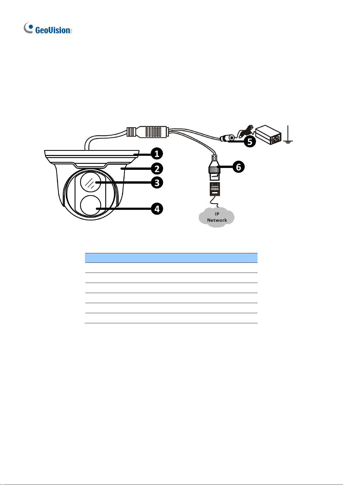
1.1.3.1 GV-EBD2702 / 4700
Figure 1-1
No. Description
1 Bottom ring
2 Housing
3 Lens
4 Infrared indicator
5 Power connector (DC 12 V)
6 Ethernet connector / PoE
4
Page 14
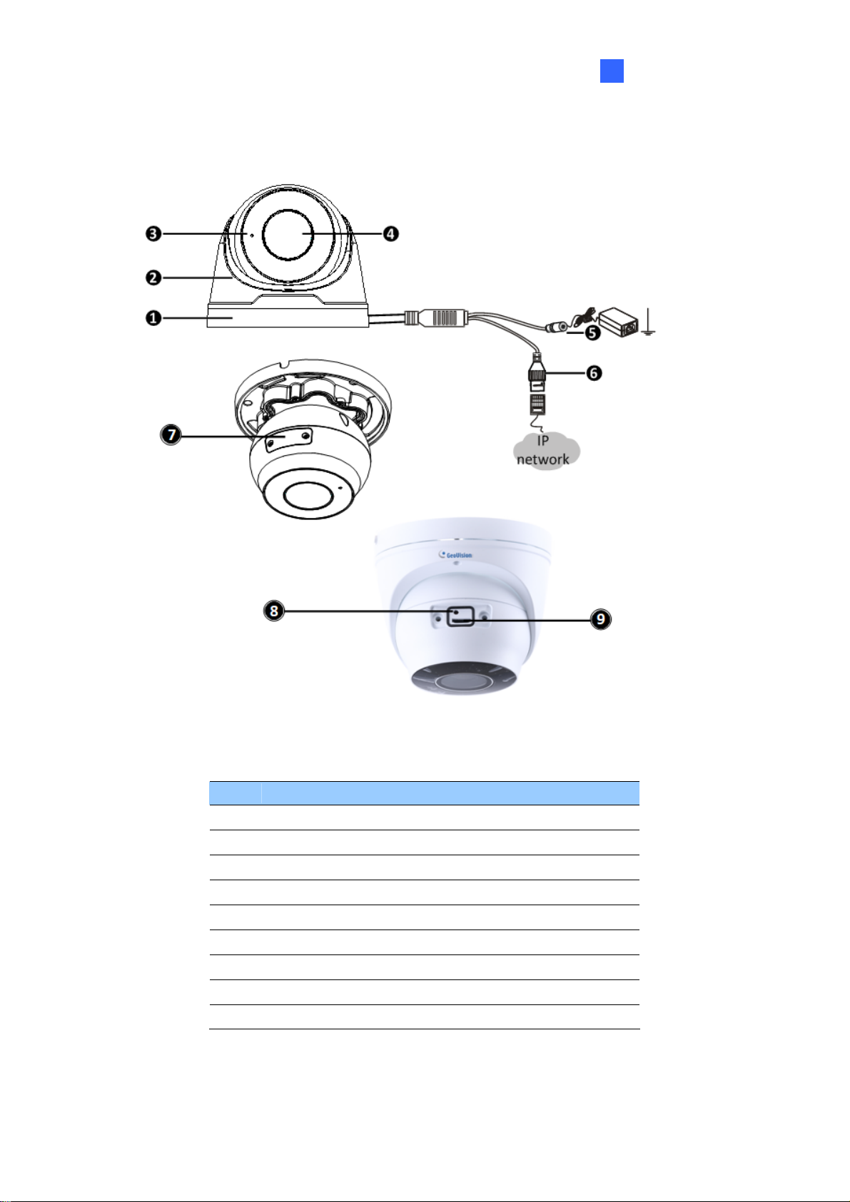
1.1.3.2 GV-EBD4711 / 8711
Introduction
1
Figure 1-2
No. Description
1 Bottom ring
2 Housing
3 Microphone
4 Lens
5 Power connector (DC 12 V)
6 Ethernet connector / PoE
7 Micro SD card slot and default button compartment
8 Default button
9 Micro SD card slot
5
Page 15
1.1.4 Installation
The Target Eyeball Dome is designed for outdoors. With the standard package, you can
install the camera on the ceiling. Alternatively, you can purchase optional mounting
accessories to mount the dome on a wall.
Below are the instructions for Ceiling Mount. There are two kinds of Ceiling Mount:
Concealed Installation and Open Installation. In concealed installation, the cables are
hidden in the ceiling. In Open Installation, the cables are led out from the open slot on the
bottom ring.
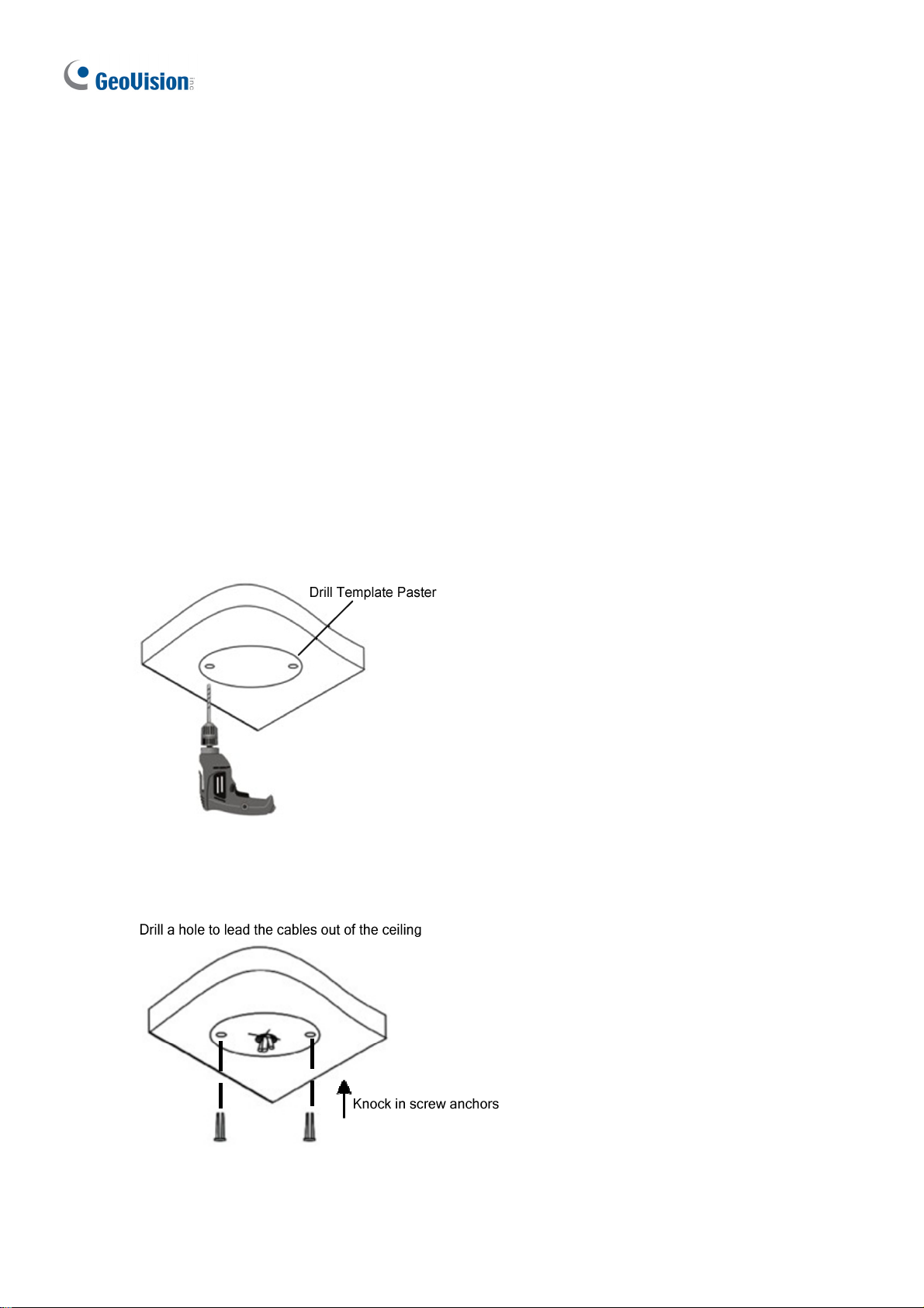
1.1.4.1 GV-EBD2702 / 4700 Standard Installation
For Concealed Installation
1. Stick the drill template paster to the ceiling and drill three holes according to the drill
template.
Figur
e 1-3
2.
Insert the screw anchors.
e 1-4
Figur
6
Page 16
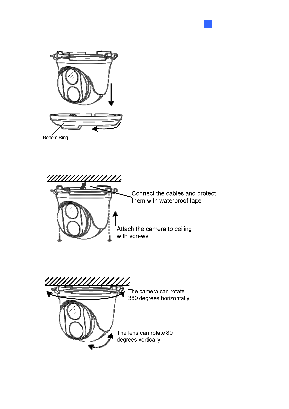
3. Remove the bottom ring by turning it anticlockwise.
Figure 1-5
Introduction
1
4. Connect the cables and secure the camera.
Figure 1-6
5. Adjust the monitoring direction.
Figure 1-7
7
Page 17
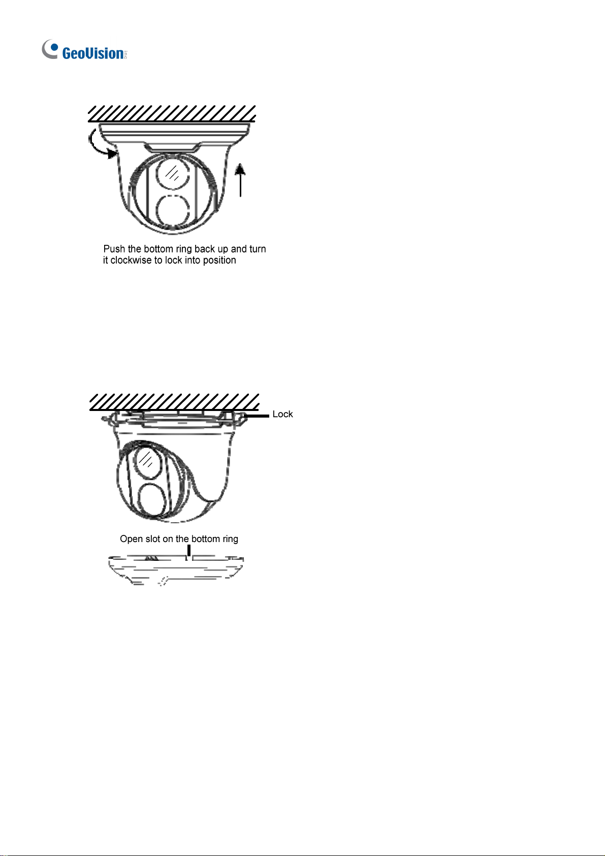
6. Mount the bottom ring.
Figure 1-8
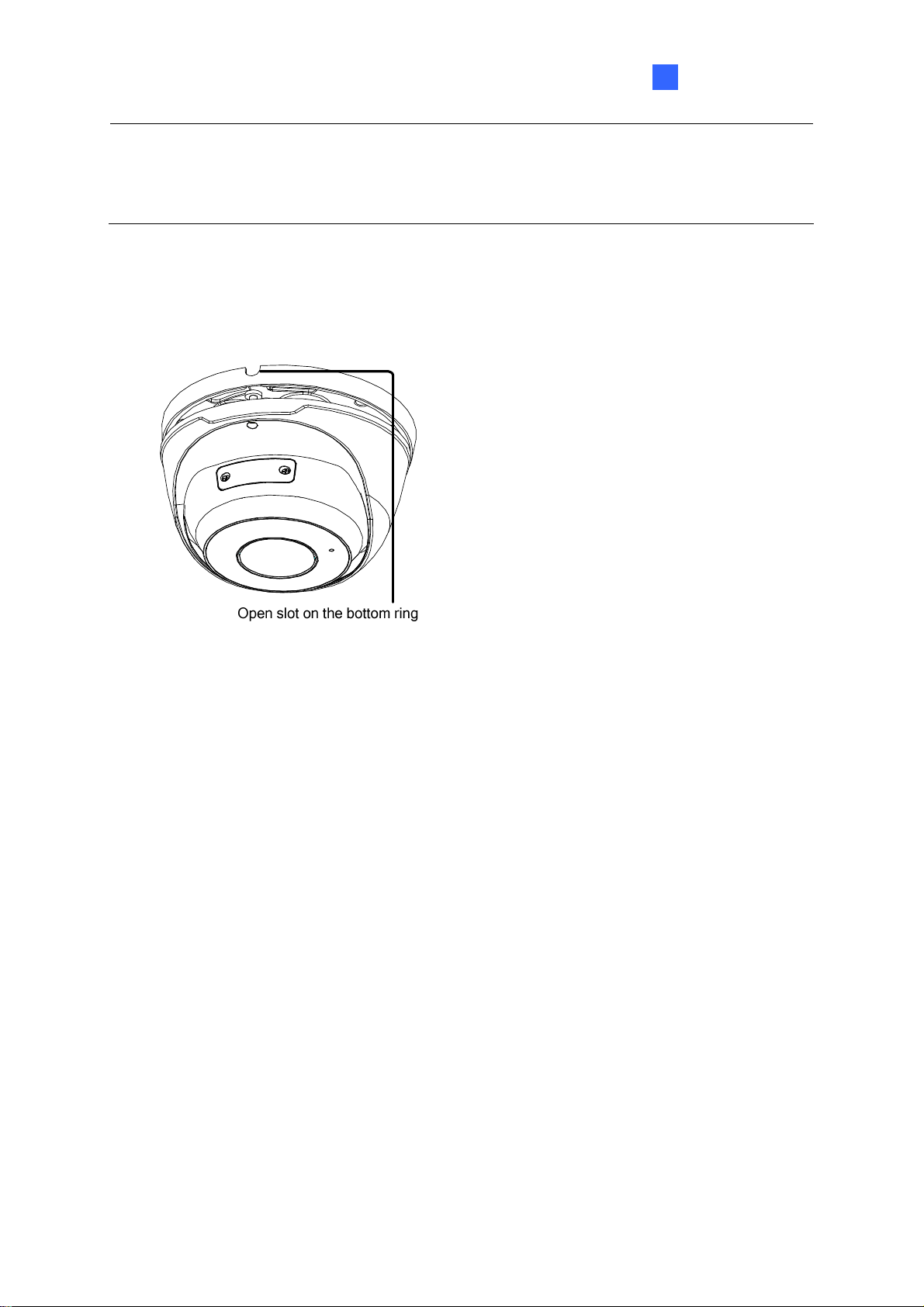
For Open Installation
Lead the cables out from the open slot on the bottom ring before screwing the camera to the
ceiling as shown in Figure 1-6.
Figure 1-9
8
Page 18
Introduction
1
1.1.4.2 GV-EBD4711 / 8711 Standard Installation
For Concealed Installation
1. Stick the drill template paster to the ceiling and drill three holes according to the drill
template.
Figure 1-10
2. Insert the screw anchors.
Figure 1-11
3. Loosen the fixing screw and remove the housing by turning it to the position as shown.
Figure 1-12
9
Page 19
4. Secure the bottom ring to the ceiling with 3 supplied screws and connect the cable.
Figure 1-13
5. Mount the housing by adjusting to the position as shown and press and turn to anywhere
but .
Figure 1-14
6. Adjust the monitoring direction. Then tighten the screw.
Figure 1-15
10
Page 20
Introduction
1
WARNING: Make sure the housing is not dismounted from the bottom ring when adjusting
the monitoring direction. Unintentional removal of the housing may result in circumstantial
damages.
For Open Installation
Lead the cables out from the open slot on the bottom ring before mounting the housing as
shown in Figure 1-14.
Figure 1-16
11
Page 21
1.1.5 Optional Installation
You can optionally purchase GV-Mount211P or GV-Mount212P for Wall Box Mount. Follow
the instructions below.
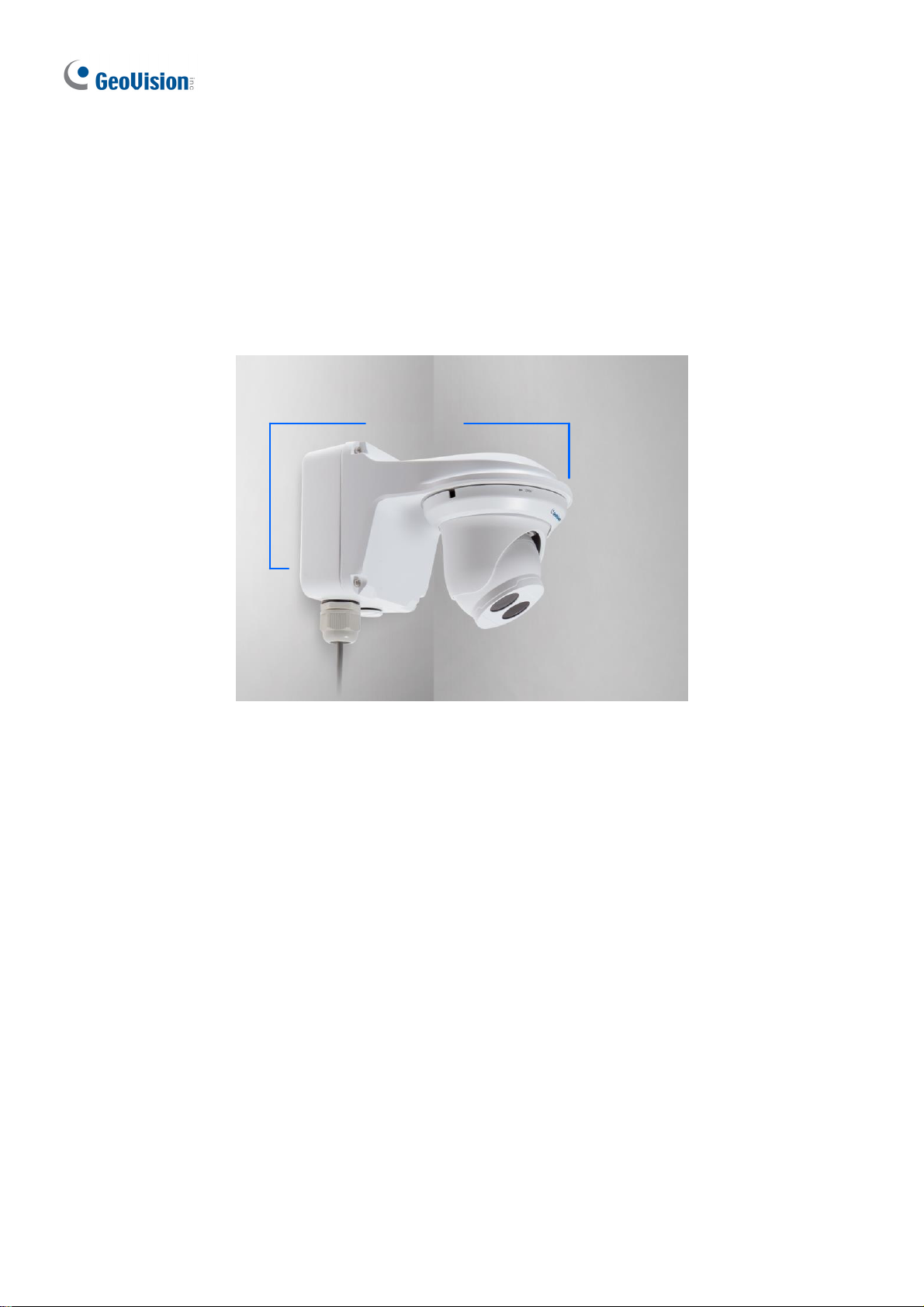
1.1.5.1 GV-Mount211P
GV-Mount211P
GV-Mount211
Figure 1-17
12
Page 22
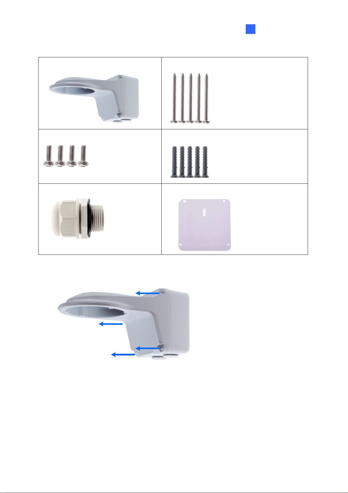
GV-Mount211P Packing List
Introduction
1
GV-Mount211P Wall Mount Bracket
Short Screw x 4
Plastic PG21 Conduit Connector
Long Screw x 5
Screw Anchor x 5
Drill Template Paster
1. Unscrew the bracket.
Figure 1-18
13
Page 23
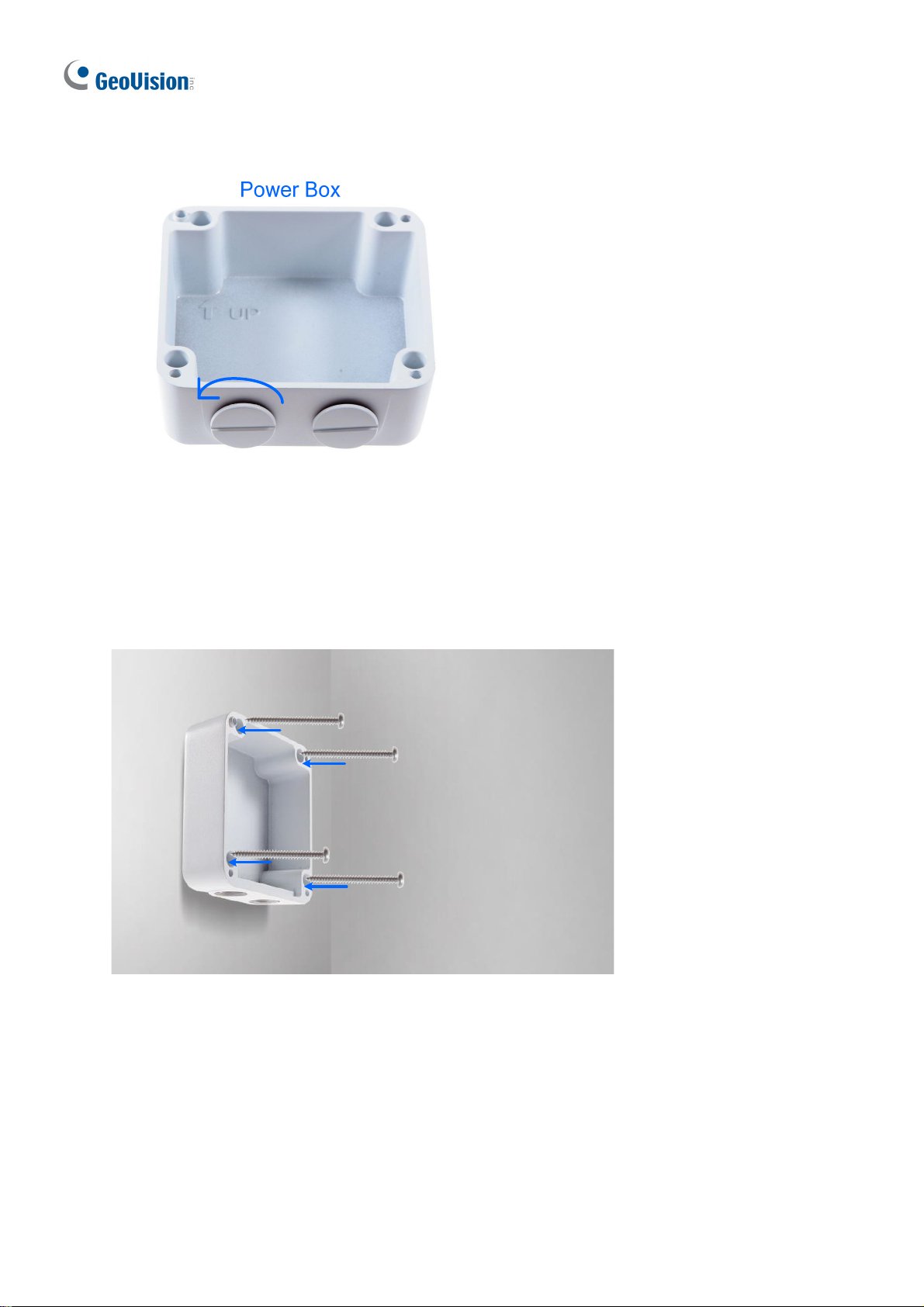
2. Loosen the indicated area by turning it anticlockwise.
Figure 1-19
3. Stick the drill template paster to the wall with the arrow pointing up.
4. Drill 4 holes according to the sticker and insert the 4 screw anchors to the 4 holes.
5. Secure the power box to the wall with 4 long screws.
14
Figure 1-20
Page 24

6. Remove the bottom ring by turning it anticlockwise.
Introduction
1
Figure 1-21
7. Thread the network and power wires through the camera housing.
15
Page 25

8. Secure the camera to the wall mount bracket with the provided short screws according to
the screw position for each model:
GV-EBD4700 / 4711 / 8711
Figure 1-22
GV-EBD2702
GV-ADR2701 / 4701
Figure 1-23
16
Figure 1-24
Page 26

Introduction
1
9. Thread the Ethernet cable through the PG21 conduit connector and the power box as
shown in No. 9, Figure 1-25.
10. Rotate the plastic ring to secure the conduit connector to the power box. Screw in the cap
as shown in No. 10, Figure 1-25.
11. Plug the Ethernet cable to the RJ-45 connector of the camera as shown in No. 11, Figure
1-25.
12. Screw the wall mount bracket to the power box as shown in No. 12, Figure 1-25.
13. Mount the bottom ring.
Figure 1-26
Figure 1-25
17
Page 27

1.1.5.2 GV-Mount212P
GV-Mount212P
Figur
GV-Mount212P Packing List
e 1-27
GV-Mount212P Wall Box Mount
Short Screw x 3
Long Screw x
Screw Anchor x
3
3
18
Page 28

Introduction
1
Standard Installation
1 Attach the wall box to the wall and use a marker to mark the location for the center
socket and the screws. Make sure the knob points down.
Screw Location
This knob points down
Figure 1-28
2 Drill 3 holes according to the screw location. Then, drill a bigger hole at the center
socket location for the Ethernet cable.
3 Insert 3 screw anchors to the screw location and secure the wall box to the wall with 3
long screws.
Figure 1-29
19
Page 29

4. Remove the bottom ring by turning it anticlockwise.
Figure 1-30
5. Thread the Ethernet cable through the center socket and waterproof the Ethernet cable.
For details, see 1.6 Waterproofing the Cable.
`
Figure 1-31
6 Fit the cable into the wall box.
20
Page 30

Introduction
1
7 Secure the camera by locking the provided short screws to the screw position for each
model:
GV-EBD2702
Figure 1-32
GV-EBD4700 / 4711 / 8711
8 Mount the bottom ring.
Figure 1-33
21
Page 31

Note: In addition to the Standard Installation, you can also choose to run the Ethernet
cable through a corrugated tube. To do this, you will have to purchase your own conduit
connector and corrugated tube. 3/4” NPS is the recommended type of connector. After you
secure the wall box to the desired location, remove the knob at the bottom and connect the
conduit connector with a self-prepared corrugated tube to the wall box. Then, thread the
Ethernet cable through the corrugated tube and waterproof the Ethernet cable.
Figure 1-34
22
Page 32

Introduction
1
1.2 GV-ABL Series
The Bullet IP Camera is an outdoor, fixed, network camera equipped with an automatic IR-
cut filter and an IR LED for day and night surveillance. The camera supports H.265 video
codec to achieve better compression ratio while maintaining high quality image at reduced
network bandwidths. The camera adheres to IP66 standards (IP67 for GV-ABL4712 / 8712)
and can be powered through PoE.
Model No. Specifications Description
GV-ABL2701-4 mm
Fixed lens
GV-ABL2701-6 mm
GV-ABL2702 Varifocal Lens
GV-ABL4701-4 mm
Fixed lens
GV-ABL4701-6 mm
Fixed Iris, f: 4.0 mm, F/1.8,
M12 Lens Mount
Fixed Iris: f: 6.0 mm,
F/1.8, M12 Lens Mount
Fixed Iris, f: 2.8~12 mm, F/1.4,
Ø14 mm Lens Mount
Fixed Iris, f: 4.0 mm, F/1.8,
M12 Lens Mount
Fixed Iris, f: 6.0 mm, F/1.8,
M12 Lens Mount
2 MP, H.265,
Low Lux, WDR
2 MP, H.265,
Low Lux, WDR Pro
4 MP, H.265
Low Lux, WDR
GV-ABL4712
GV-ABL8712
Motorized
varifocal lens
4 MP, H.265
Low Lux, WDR Pro
Fixed Iris, f: 2.8~12 mm, F/1.4,
Ø14 mm Lens Mount
8 MP, H.265
Super Low Lux,
WDR Pro
23
Page 33

1.2.1 Packing List
Bullet IP Camera Waterproof Rubber Set
Scr
ew Kit
Download Gu
Drill Template Paster
ide W
arranty Card
24
Page 34

Introduction
1
1.2.2 Optional Accessories
Optional accessories can expand the capabilities and versatility of your camera. Contact your
dealer for more information.
Model Number Name Details
GV-Mount502 (for GVABL2701 Series / 4701
Series)
GV-Mount503 (for GVABL2702 / 4712 / 8712)
GV-PA191
GV-POE Switch
Wall Mount Bracket
Dimensions: 93 x 93 x 39 mm
(3.66” x 3.66” x 1.53”)
Weight: 0.235 kg (0.52 lb)
Wall Mount Bracket
Dimension: 125 x 125 x 55
mm (4.9” x4.9” x2.2”)
Weight: 0.74 kg (1.63lb)
Power over Ethernet (PoE)
Adapter
GV-PA191 is a Power over
Ethernet (PoE) adapter
designed to provide power to
the IP device through a single
Ethernet cable.
GV-POE Switch is designed to provide power along with
network connection for IP devices. GV-POE Switch is available
in various models with different numbers and types of ports.
Power Adapter
Contact our sales representatives for the countries and areas
supported.
25
Page 35

1.2.3 Overview
1.2.3.1 GV-ABL2701 Series / 4701 Series
Figure 1-35
No. Description
1 Power connector (DC 12 V)
2 Ethernet connector / PoE
26
Page 36

1.2.3.2 GV-ABL2702 / 4712 / 8712
Introduction
1
1
2
3
4
5
Figure 1-36
No. Description
1 Power connector (DC 12 V)
2 Audio input / Audio output / GND
3 Alarm input (IN, GND) / Alarm output (N,P)
4 Ethernet connector / PoE
5 Video Output (GV-ABL8712 Only)
27
Page 37

1.2.4 Installation
The Bullet IP Camera is designed for outdoors. With the standard package, you can install
the camera on the wall or ceiling. Or, you can purchase optional mounting accessories to
mount your camera on a wall.
Below are the instructions for Wall Mount. There are two kinds of Wall Mount: Concealed
Installation and Open Installation. In Concealed Installation, the cables are hidden in the
wall. In Open Installation, the cables are led out from the open slot on the base.
For Concealed Installation
1. For
2. Stick the drill template paster to the wall and align the cross center to the hole in the wall.
3. Lead the cables across the hole on the wall.
GV-ABL2702 / 4712 / 8712, optionally loosen the two screws at the bottom of t
mera to insert a SD card
ca
.
Figure 1-37
he
28
Figure 1-38
Page 38

4. Drill four 30-mm deep holes according to the drill template.
Figure 1-39
5. Insert the screw anchors.
Introduction
1
Figure 1-40
6. Screw the locknut and loosen the universal joint before attaching the camera to the wall.
Figure 1-41
29
Page 39

7. Secure the camera to the wall and connect all cables.
Leadtappingscrewsthrough
theguideholesinthebase
andfixthemonthewallby
usingascrewdriver.
Figure 1-42
8. Adjust the monitoring direction.
Figure 1-43
For Open Installation
Lead the cables out from the open slot on the base before screwing the camera to the wall
as shown in Figure 1-42.
30
Page 40

Introduction
1
1.2.5 Optional Installation
For other installation methods, you can optionally purchase GV-Mount502 for GV-ABL2701
Series / 4701 Series or GV-Mount503 for GV-ABL2702 / 4712 / 8712.
Figure 1-44 Figure 1-45
31
Page 41

1.2.5.1 GV-Mount502
GV-Mount502 Packing List
GV-Mount502 Wall Mount Box
M3 12 mm Screw x 4
Plastic PG21 Conduit Connector
M3 25 mm Screw x
Screw Anchor x
4
4
1.
Unscrew the box cover.
Figure 1-46
32
Page 42

2. Loosen the indicated area by turning it anticlockwise.
Figure 1-47
Introduction
1
3. Attach the box to the wall with the arrow pointing up and use a marker to mark 4 dots.
Figure 1-48
4. Drill 4 holes according to the marks and insert the 4 screw anchors to the 4 holes.
33
Page 43

5. Secure the power box to the wall with four M3 25 mm screws.
Figure 1-49
6. Thread the network and power wires through the wall mount box cover.
7.
Secure the camera to the wall mount box cover with 4 M3 12 mm screws.
34
Figure 1-50
Page 44

Introduction
1
8. Thread the Ethernet cable through the PG21 conduit connector and the wall mount box
as shown in No. 8, Figure 1-51.
9. Rotate the plastic ring to secure the conduit connector to the wall mount box. Screw in
the cap as shown in No. 9, Figure 1-51.
10. Plug the Ethernet cable to the RJ-45 connector of the camera as shown in No. 10, Figure
1-49. To waterproof the Ethernet cable, see 1.6 Waterproofing the Cable.
11. Arrange the cables.
12. Screw the wall mount box cover to the wall mount box as shown in No. 12, Figure 1-51.
Figure 1-51
35
Page 45

1.2.5.2 GV-Mount503
GV-Mount503 Packing List
GV-Mount503 Wall Mount Box
Short Screw x 4
Plastic PG21 Conduit Connector
Long Screw x
Screw Anchor x
Waterproof Rubber Plug
4
4
. Optionally insert a SD card
1
e 1-52
Figur
36
.
Page 46

2. Unscrew the box cover.
Introduction
1
Figure 1-53
3. Loosen the indicated area by turning it anticlockwise.
Figure 1-54
4. Attach the power box to the wall with the arrow pointing up and use a marker to mark 4
dots.
Figure 1-55
37
Page 47

5. Drill 4 holes according to the marks and insert 4 screw anchors to the 4 holes.
6. Secure the power box to the wall with 4 long screws.
7. Thread the camera cable through the box cover.
8. Secure the camera to the box cover with 4 short screws.
Figure 1-56
9. Thread the Ethernet cable through the PG21 conduit connector and the power box as
shown in No 9, Figure 1-57.
10. Rotate the plastic ring to secure the conduit connector to the power box. Secure in the
cap as shown in No 10, Figure 1-57
11. Plug the Ethernet cable to the RJ-45 connector of the camera.
12. Connect other wires to the camera.
13. Secure the box cover to the power box as shown in No 13, Figure 1-57
38
Figure 1-57
Page 48

Introduction
1
1.3 GV-ADR Series
The IR Mini Fixed Rugged IP Dome is an outdoor, fixed, network camera equipped with an
automatic IR-cut filter and an IR LED for day and night surveillance. The camera supports
H.265 video codec to achieve better compression ratio while maintaining high quality image
at reduced network bandwidths. The camera adheres to IP66 standard and can be powered
through PoE.
Model No. Specifications Description
GV-ADR2701 Fixed lens
GV-ADR4701 Fixed lens
Fixed Iris, f: 2.8 mm,
F/2.2, M12 Lens Mount
Fixed Iris, f: 2.8 mm,
F/1.8, M12 Lens Mount
2 MP, H.265,
Low Lux, WDR
4 MP, H.265,
Low Lux, WDR
39
Page 49

1.3.1 Packing List
IR Mini Fixed Rugged IP Dome
Scr
ew Kit
Waterproof Rubber Set
Drill Template Paster
Download Gu
ide W
arranty Card
40
Page 50

Introduction
1
1.3.2 Optional Accessories
Optional accessories can expand the capabilities and versatility of your camera. Contact your
dealer for more information.
Model Number Name Details
GV-Mount211P Wall Mount Bracket
GV-Mount213 Wall Box Mount
GV-PA191
Power over Ethernet (PoE)
Adapter
GV-POE Switch
GV-POE Switch is designed to provide power along with
network connection for IP devices. GV-POE Switch is available
in various models with different numbers and types of ports.
Dimensions: 233 x 126 x 126
mm (9.2” x 5” x 5”)
Weight: 1 kg (2.2 lb)
Dimensions: Ø 109 x 39 mm
(4.3” x 1.5”)
Weight: 0.2 kg (0.44 lb)
GV-PA191 is a Power over
Ethernet (PoE) adapter
designed to provide power to
the IP device through a single
Ethernet cable.
Power Adapter
Contact our sales representatives for the countries and areas
supported.
41
Page 51

1.3.3 Overview
Figure 1-58
No. Description
1 Ethernet connector / PoE
2 Power connector (DC 12 V)
3 Transparent Dome Cover
42
Page 52

Introduction
1
1.3.4 Installation
The IR Mini Fixed Rugged IP Dome is designed for outdoors. With the standard package,
you can install the camera on the ceiling.
Below are the instructions for Ceiling Mount. There are two kinds of Ceiling Mount:
Concealed Installation and Open Installation. In Concealed Installation, the cables are
hidden in the ceiling. In Open Installation, the cables are led out from the open slot on the
camera base.
For Concealed Installation
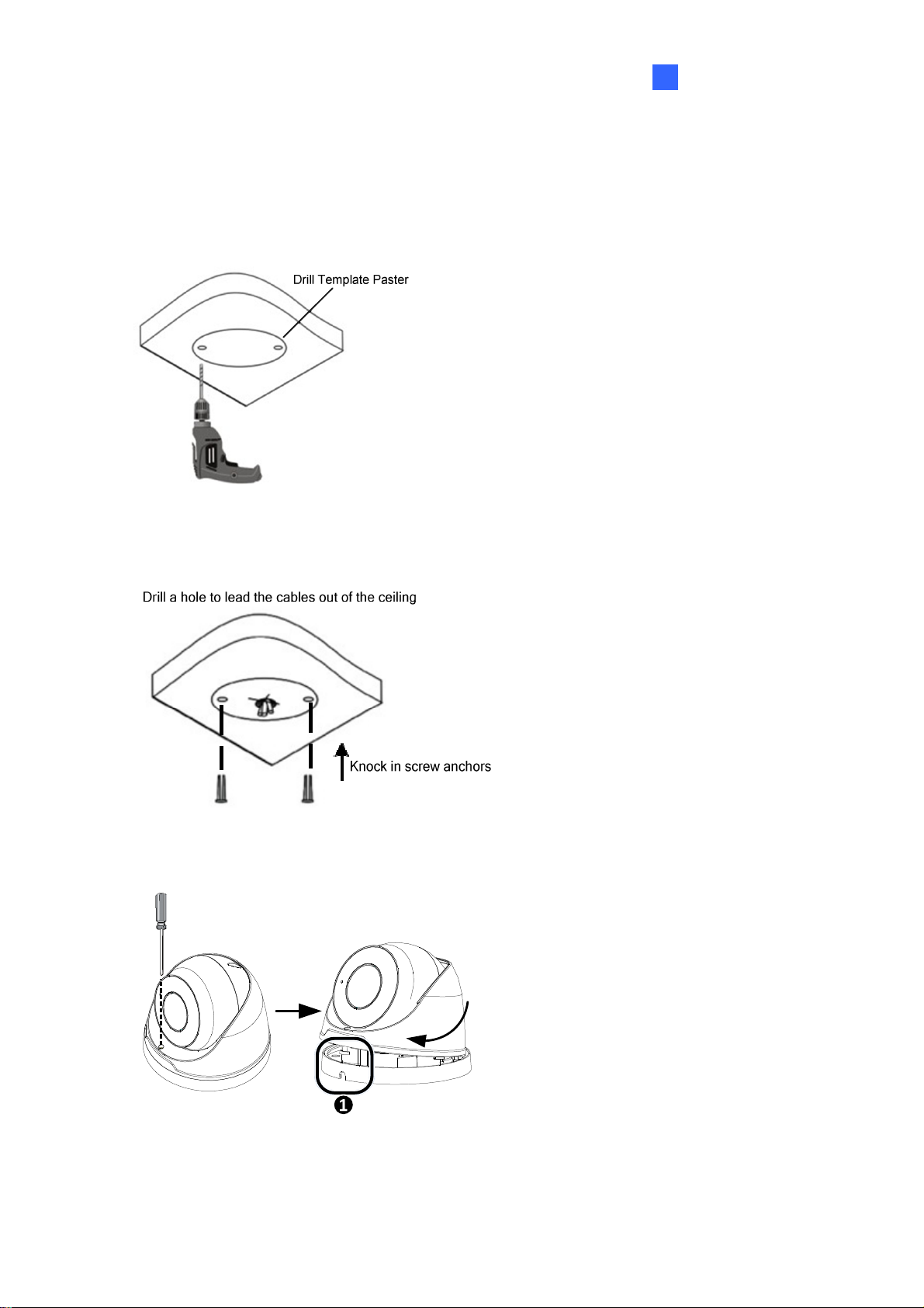
1. Stick the drill template paster to the ceiling and drill 30-mm deep holes according to the
drill template.
Figure 1-59
2. Insert the screw anchors.
Figure 1-60
43
Page 53

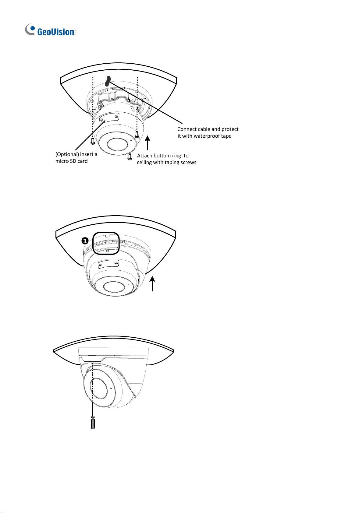
3. Unscrew the transparent dome cover with the supplied torx wrench.
4.
Connect the cables and secure the camera.
Figure 1-61
5. Adjust the monitoring direction and tighten the screws after vertically adjusting the lens.
Figure 1-62
44
Page 54

6. Secure the transparent dome cover with the supplied torx wrench.
Introduction
1
Figure 1-63
Note: Before securing the transparent dome cover, make sure the waterproof rubber strip is
tightly held by the six retainers on the bottom ring.
Figure 1-64
For Open Installation
Lead the cables out from the open slot on the camera base before screwing the camera to
the ceiling as shown in Figure 1-61.
45
Page 55

1.3.5 Optional Installation
You can optionally purchase GV-Mount211P or GV-Mount213 to install the camera on the
wall or ceiling. Follow the instructions below.
1.3.5.1 GV-Mount211P
To install GV-Mount211P Wall Box Mount, see 1.1.5.3.1 GV-Mount211P for installation
instructions.
1.3.5.2 GV-Mount213
46
Figure 1-65
Page 56

GV-Mount213 Packing List
Introduction
1
GV-Mount213 Wall Box Mount
Short Screw x 3
Long Screw x 3
Screw Anchor x 3
Standard Installation
1. Attach the wall box to the wall and use a marker to mark the location for the center socket
and the screws.
Figure 1-66
47
Page 57

Note: To prevent rain from getting into the camera,
For wall mount installation, make sure the indicated hole points down and towards the
ground.
For ceiling mount installation, turn the indicated hole inwards.
Figure 1-67
2. Drill 3 holes according to the screw locations. Then, drill a bigger hole at the center
socket location for the Ethernet cable.
3. Insert 3 screw anchors to the screw locations and secure the wall box to the wall with 3
long screws.
4. Thread the Ethernet cable through the center socket and waterproof the Ethernet cable.
For details, see 1.6 Waterproofing the Cable.
48
Figure 1-68
Page 58

Introduction
1
5. Fit the cable into the wall box.
6. Remove the camera cover and fasten the camera to the wall box as indicated below
using the supplied 3 short screws.
Figure 1-69
7. Secure the camera cover.
Note: In addition to the Standard Installation, you can also choose to run the Ethernet
cable through a corrugated tube. To do this, see Figure 1-33 and its related Note.
49
Page 59

1.4 GV-AVD Series
The Vandal Proof IP Dome is an outdoor camera designed with IK10 vandal resistance and
IP67 ingress protection. The camera is equipped with an automatic IR-cut filter and IR LEDs
for day and night surveillance. Adjustable in 3 axes (pan, tilt and rotate), it offers an entry-
level surveillance solution with all the essential features and excellent image quality.
Model No. Specifications Description
GV-AVD2700 Varifocal lens
GV-AVD4710
Motorized
varifocal lens
GV-AVD8710
Fixed Iris, f: 2.8~12 mm,
F/1.4, Ø14 mm Lens
Mount
Fixed Iris, f: 2.8~12 mm,
F/1.5, Ø14 mm Lens
Mount
2MP, H.265,
Low Lux, WDR
4 MP, H.265,
Low Lux, WDR Pro
8 MP, H.265,
Super Low Lux,
WDR Pro
50
Page 60

1.4.1 Packing List
Introduction
1
IR Vandal Proof IP Dome
Screw Kit
Torx Wrench
Waterproof Rubber Set
Drill Template Paster
Download Guide
Warranty Card
51
Page 61

1.4.2 Optional Accessories
Optional accessories can expand the capabilities and versatility of your camera. Contact your
dealer for more information.
Model Number Name Details
ensions: 253 x125 x 125 mm
GV-Mount211-2 Wall Mount Bracket
GV-Mount212-2 Wall Box Mount
Dim
(10” x 4.9” x 4.9”)
Weight: 0.92 kg (2.02lb)
Dim
ensions: Φ145 x 40 mm (5.7” x
1.6”)
Weight: 0.24 kg (0.5lb)
GV-PA191
GV-POE Switch
Power Adapter
Power over Ethernet (PoE)
Adapter
GV-POE Switch is designed to provide power along with network
connection for IP devices. GV-POE Switch is available in various
models with different numbers and types of ports.
Contact our sales representatives for the countries and areas
supported.
V-PA191 is a Power over
G
Ethernet (PoE) adapter designed
to provide power to the IP device
through a single Ethernet cable.
52
Page 62

1.4.3 Overview
Introduction
1
Figure 1-70
6
7
Figure 1-71
No. Description
1 Power connector (DC 12 V)
2 Ethernet connector / PoE
3 Video output
4 Audio input / Audio output / GND
5 Alarm input (IN,GND) / Alarm output (N,P)
6 Default button
7 Micro SD card slot
53
Page 63

1.4.4 Installation
The Target Vandal Proof Dome is designed for outdoors. With the standard package, you
can install the camera on the ceiling. Alternatively you can purchase optional mounting
accessories to mount the camera on a wall.
Below are the instructions for Ceiling Mount. There are two kinds of Ceiling Mount:
Concealed Installation and Open Installation. In Concealed Installation, the cables are
hidden in the ceiling. In Open Installation, the cables are led out from the open slot on the
camera base.
For Concealed Installation
1. Stick the drill template paster to the ceiling, and then drill three holes according to the drill
template.
Figure 1-72
2. Insert the screw anchors.
Figure 1-73
3. Unscrew the transparent dome cover with the supplied torx wrench.
54
Page 64

4. Connect the camera cables and secure the camera.
Introduction
1
Figure 1-74
5. Insert a SD card into the slot.
6. Adjust the monitoring direction and tighten the screws after vertically adjusting the lens.
Figure 1-75
7. Secure the transparent dome cover with the supplied torx wrench.
For Open Installation
Lead the cables out from the open slot on the camera base before screwing the camera to
the ceiling as shown in Figure 1-74.
55
Page 65

1.4.5 Optional Installation
1.4.5.1 GV-Mount211-2
Figur
e 1-76
GV-Mount211-2 Packing List
GV-Mount211-2 Wall Mount Bracket
Short Screw x 4
Plastic PG21 Conduit Connector
Long Screw x
Screw Anchor x 5
Drill Template Paster
5
56
Page 66

Introduction
1
1. To install the power box from the wall mount bracket on the wall, follow steps 1 to 5 in
1.1.5.1 GV-Mount211P.
2. Unscrew the transparent dome cover with the supplied torx wrench.
Figure 1-77
3. Optionally insert a SD card into the slot.
4. Thread the camera cables through the bracket.
5. Secure the camera to the wall mount bracket with the provided short screws.
Figure 1-78
57
Page 67

6. Thread the Ethernet cable through the PG21 conduit connector and the power box as
shown in No 6, Figure 1-78.
7. Rotate the plastic ring to secure the conduit connector to the power box. Screw in the cap
shown in No 7, Figure 1-78.
8. Plug the Ethernet cable to the RJ-45 connector of the camera
9. Screw the wall mount bracket to the power box as shown in Figure 1-78.
Figure 1-79
58
Page 68

1.4.5.2 GV-Mount212-2
GV-Mount212-2
Introduction
1
Figure 1-80
GV-Mount212-2 Packing List
GV-Mount212-2 Wall Box Mount
Short Screw x 3
Long Screw x 3
Screw Anchor x 3
59
Page 69

1. Attach the wall box to the wall and use a marker to mark the location for the center socket
and the screws. Make sure the knob points down.
Screw Location
This knob points down
Figure 1-81
2. Drill 3 holes according to the screw location. Then, drill a bigger hole at the center socket
location for the Ethernet cable.
3. Insert 3 screw anchors to the screw location and secure the wall box to the wall with 3
long screws.
4. Thread the Ethernet cable through the center socket, connect other wires and fit the
camera cable into the wall box. See 1.6 Waterproofing the Cable.
Figure 1-82
5. Unscrew the transparent dome cover with the supplied torx wrench.
60
Page 70

6. Secure the camera to the wall box.
Figure 1-83
Introduction
1
Note: In addition to the Standard Installation, you can also choose to run the Ethernet
cable through a corrugated tube. To do this, see Figure 1-33 and its related Note.
61
Page 71

1.5 System Requirements
CPU Intel Core i5-4670, 3.40 GHz
Memory DDR3 8 GB RAM
On Board Graphics Intel HD Graphics 4600 (Versions of driver from year 2014 or later
required)
Web Browsers Internet Explorer 11.0 or above
M
Safari
Note: Some functions are not available on non-IE browsers.
ozilla Firefox
62
Page 72

1
1.6 Waterproofing the Cable
Waterproof the Ethernet cable by using the supplied waterproof rubber set.
1. Attach the seal ring to the RJ-45 plug.
Sealring
Figure 1-84
Introduction
2. Insert the waterproof components through the Ethernet cable as shown below.
3
2
Insertinorder
Figure 1-85
3. Insert the cylindrical waterproof ring into waterproof bolt.
Cylindricalwaterproofring
Waterproofbolt
Figure 1-86
63
Page 73

4. Insert the cable into the RJ-45 plug and screw the waterproof bolt in.
Figure 1-87
5. Screw in the waterproof bolt lid.
Bolt lid
Figure 1-88
6. Finish the waterproof installation.
Figure 1-89
64
Page 74

Chapter 2 Accessing the Camera
Once installed, the IP camera is accessible on a network. Follow these steps to configure the
network settings and access your surveillance images.
2.1 Installing on a Network
These instructions describe the basic connections to install the camera on the network.
1.
Using a standard network cable, connect the camera to your network.
2.
Connect to power using one of the following methods:
Use the optional power adapter to connect to power.
Use the Power over Ethernet (PoE) function in which power is supplied over t
work cable.
net
You can now access the Web interface of the camer
3.
If the camera is installed in a LAN with DHCP server, use GV-IP Device Utility to look
up the camera’s dynamic IP address. See 2.1.1 Checking the Dynamic IP Address
If the camera is installed in a LAN without DHCP server, the default IP addr
168.0.10 is applied. To assign a different static IP address, see 2.1.2
192.
P Address
an I
e: You must set your browser to allow ActiveX Control and perform a one-time
Not
installation of the ActiveX component onto your computer upon your first login.
.
a.
he
.
ess
Assigning
65
Page 75

2.1.1 Checking the Dynamic IP Address
Follow the steps below to look up the IP address and access the Web interface.
1. Download and install the GV-IP Device Utility program from the company website.
Note: The PC installed with GV-IP Device Utility must be under the same LAN as the
camera you wish to configure.
2. On the GV-IP Utility window, click the button to search for the IP devices connected
in the same LAN. Click the Name or Mac Address column to sort.
Figure 2-1
3. Find the camera with its Mac Address, click on its IP address and select Web Page.
Figure 2-2
66
 Loading...