

Service Manual
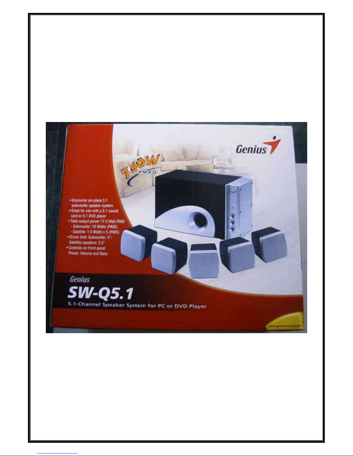
SW-Q5.1

Service Manual
Table of Contents
SW-Q5.1.......................................................................................................................................0
Chapter 1. INTRODUCTION...........................................................................................................2
Function Block.............................................................................................................................2
Chapter 2. Troubleshooting Guide....................................................................................................3
Chapter 3. Removal and Replacement..............................................................................................4
Disassemble & Assemble the Functional cover...........................................................................4
Disassemble & Assemble the PCBA(SUB).................................................................................5
Disassemble & Assemble Transformer........................................................................................6
Chapter 4. Parts list...........................................................................................................................7
Chapter 5. Tools................................................................................................................................8
Version 1.0
P
age 1

Service Manual
Chapter 1. INTRODUCTION
Function Block
TRANSFORMER
SUB
FL SPK
FR SPK
RR SPK
CEN SPK
RL SPK
INPUT SIGNAL
Version 1.0
P
age 2

Service Manual
Chapter 2. Troubleshooting Guide
Problems Condition Probable Reasons Solutions
1.no power 1.9 Pin cable 1.cable broken 1.replace cable
2.Transformer 1.Transformer open 1.replace Transformer
3.PCBA 1.Bridge Diode NG 1.replace Bridge Diode
2.Transistor NG 1.replace Transistor
3.IC NG 1.replace IC
2.display L.E.D. unlight 1.cover broken 1.L.E.D. broken or NG 1.replace L.E.D.
2.PCBA 1.L.E.D. pin problem 1.Resoldering L.E.D.
3.button NG 1.button 1.button NG 1.replace button
4.no sound 1.signal cable 1.signal cable NG 1.replace signal cable
2.PCBA 1. PCBA NG 1.replace PCBA
2.RCA socket NG 1.replace RCA socket
5.noise 1.speaker 1.speaker NG 1.replace speaker
2.PCBA 1.PCBA NG 1.replace PCBA
Version 1.0
P
age 3

Service Manual
Chapter 3. Removal and Replacement
Disassemble & Assemble the Functional cover
Step 1
Remove the two caps.
*Mark the position of the caps
Step 2
To remove 6 screws. After taking all
screws off, you can take up the
functional cover
*To install the functional cover,
reverse the steps shown above.
A
E C
F B D
Version 1.0
P
age 4

Service Manual
Disassemble & Assemble the PCBA(SUB)
Step 1
*Disassemble the functional
cover first.
To remove 4 screws.
Step 3
To remove screw.
*Mark the position of the
cables first.
To solder 4 cables. You can
take out the PCBA
*To install the PCBA,
reverse the steps shown
above.
B
C
D
A
Version 1.0
P
age 5

Service Manual
Disassemble & Assemble Transformer
Step 1
*Disassemble the functional cover first.
Remove all screws.
Step 3
After taking all screws off, you can take
out the Transformer
*To install the Transformer, reverse the
steps shown above.
H E
A D
J
I
C B
F G
Version 1.0
P
age
6

Service Manual
Chapter 4. Parts list
Item Part number Description Remark
1 20700011101 PCBA
2 10300025100 TDA 2822
3 10300026100 BA 5417
4 J29-57253-11G Transformer
5
6
7
Version 1.0
P
age
7

Service Manual
Chapter 5. Tools
1. VCD or DVD Player
2. MUSIC CD or DVD
1. Soldering-Iron (40W)
1. Tweezers
2. Screwdriver
3. Pliers
4. Multimeter
5. Glue-heater
Version 1.0
P
age 8
 Loading...