

Page 1
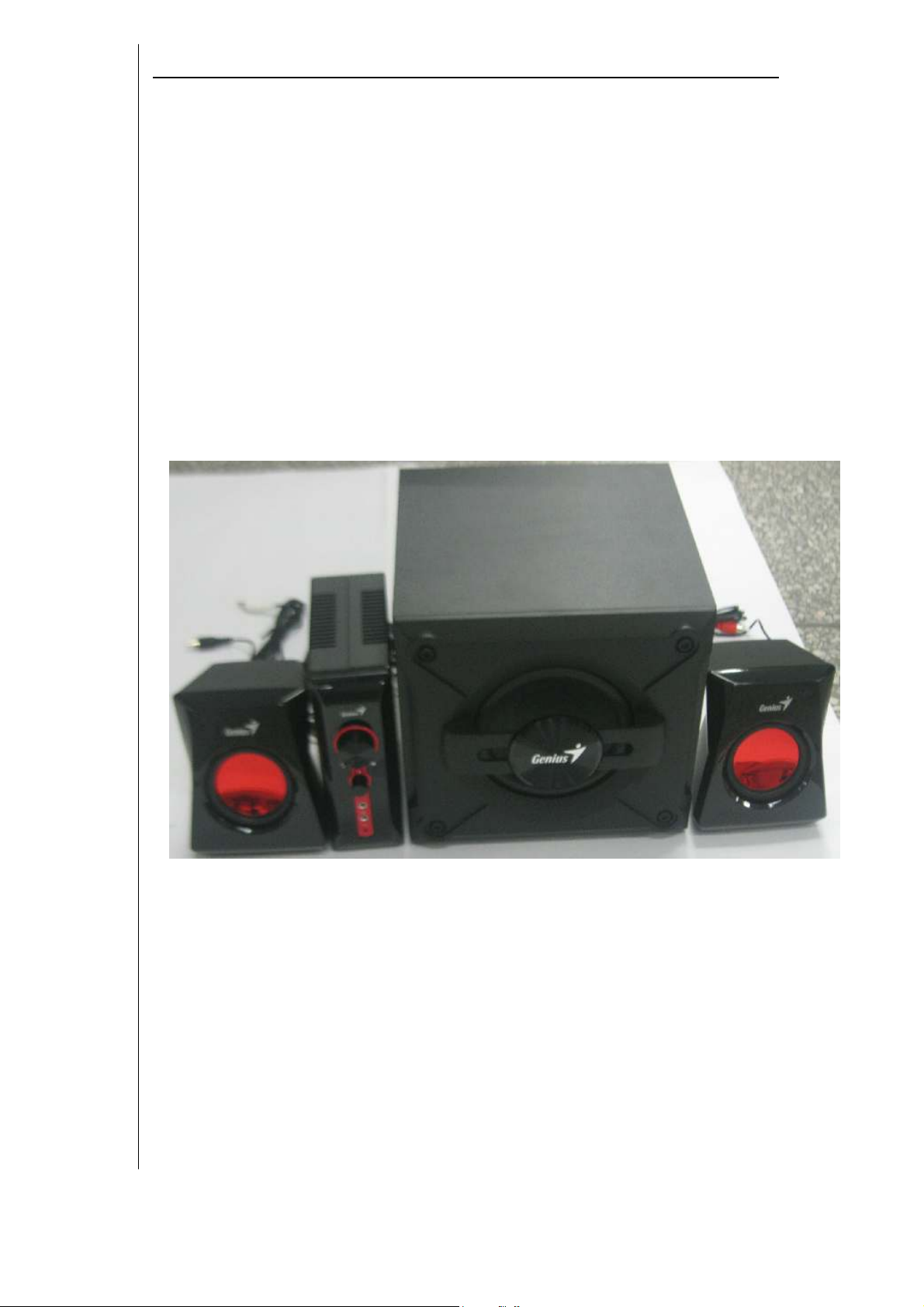
Service Guide Model No : SW-G2.1 1250
SERVICE GUIDE
KYESYSTEMS CORP.
Page 1/17
Page 2

Service Guide Model No : SW-G2.1 1250
Revision History
Version
1.0
Date
03/09/2010
Change
First Release
Page 2/17
Page 3

Service Guide Model No : SW-G2.1 1250
Table of Contents
Revision History …………………………………………………………………….2
Table of Contents ……………….……………………………………………………3
Getting Started ……………………………………………………………………….4
Conventions Used in this Guide ……………………….…..………………....4
Safety Precautions …….……………………………………………………..4
Chapter 1. How to Handle Defective Returns……………………………………..5
1.1 Speaker no sound
1.2 Power LED no light
1.3 Headphone no sound
1.4 Bass/Volume no function
Chapter 2. Specifications ………………………………………………………….10
Chapter 3. Block Diagram ……………………………………………………….11
Chapter 4. Exploded View …………………………………………………12 & 13
Chapter 5. Part List ………………………………………………………………14
Chapter 6. Schematic Diagram …………………………………………………..15
Chapter 7. Important Notes ………………………………………………………16
7.1 Packing Requirement for Sending the PCB Assembly by Post …..16
7.2 Short of Spare Parts while Repairing a Speaker System …………16
Page 3/17
Page 4

Service Guide Model No : SW-G2.1 1250
Getting Started
Conventions Used in this Guide
Pay Special Attention : Instructions that are important to remember and
may prevent mistakes .
Caution : Information that, if not followed, may result in damage to the
product .
Safety Precautions
The following precautions should be observed in handling the speaker
Described in this guide :
Place the speakers on a flat, level and stable surface.
Do not place the speakers in environments subject to mist, smoke,
vibration, excessive dust, salty or greasy air, or other corrosive gases
and fumes.
Do not drop or jolt the speakers.
Do not allow anything to drop into the subwoofer case through its
ventilator, as it could result in fatal electric shock or fire .
Place the unit far enough from other equipments for good heat
dissipation .
Disconnect the AC power cord from the AC outlet before performing
any maintenance on the speakers .
Do not perform any maintenance with wet hand .
Prevent foreign substances, such as water, other liquids or chemicals ,
From entering the speakers while performing maintenance procedures
on the speakers .
Page 4/17
Page 5
Service Guide Model No : SW-G2.1 1250
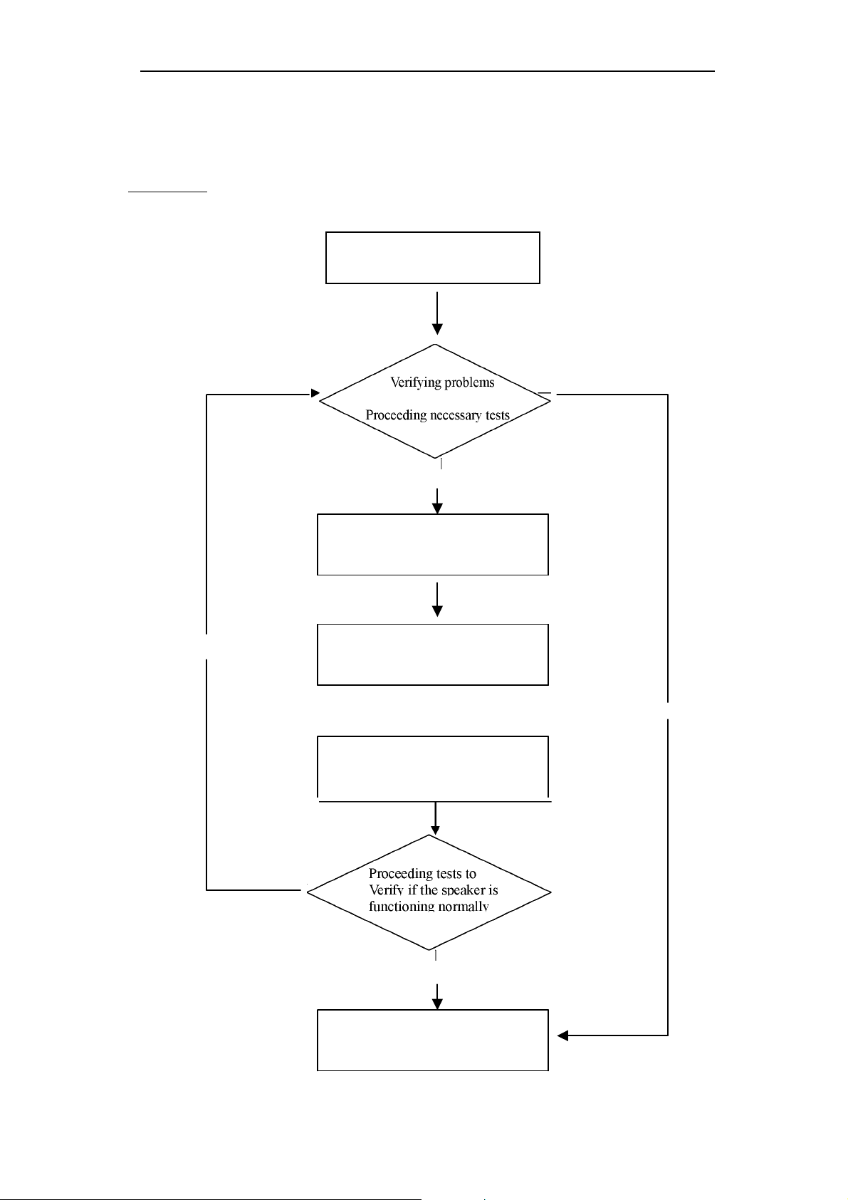
Chapter 1. How to Handle Defective Returns
Overview
Receiving Defective speakers from
Customers
Function NG
__ __
Analyzing possible malfunction
causes
Function NG
Deciding & proceeding the
rectification methods
Replace necessary defective parts
Function OK
Return the speakers with proper
repackaging to customers
Function OK
Page 5/17
Page 6

Service Guide Model No : SW-G2.1 1250
Problems
Item Problem Description
1.1 Speaker no sound
1.2 Power LED no light
1.3 Headphone no sound
1.4 Bass/Treble/Volume no function
Page 6/17
Page 7

Service Guide Model No : SW-G2.1 1250
Circuit
Speaker cable disconnect,
speaker damaged
Replace defective
IC
Reconnect speaker cable or
driver and component
Attention
Please follow the numbered sequence marked within parenthesis given in individual Flow
chat, in that this is the best-recommended sequence to rectify the problems.
1.1 One or more channels no sound (Line in/Audio in jack no function)
Problem
Analyze
and
Identify
Cause
Solution
Component cold
solder or Short
Check solder
point on PCBA
Speaker no sound
& U3
Defective U1,U2
Check and
J1, J2 & JK1defective or
replace defective speaker
Page 7/17
Page 8

Service Guide Model No : SW-G2.1 1250
Circuit
Replace defective
IC
or Fuse
Circuit
Phone
1.2 Power LED no light
Problem
Analyzer and
Identify the Causes
Solutions
Component cold
solder or Short
Check solder
point on PCBA
Power LED no light
Defective
IC001,D200,BD1,
T100, PC100,
IC200 or F001
Check and
Power Switch(VR1) or
Replace defective Power
LED defective
Switch or LED
1.3 Headphone no sound
Problem
Analyzer and
Identify the Causes
Solution
Component cold
solder or Short
Check solder
point on PCBA
Headphone no sound
J4 Phone jack defective
Replace defective J4
jack
Page 8/17
Page 9

Service Guide Model No : SW-G2.1 1250
Circuit
1.4 Bass/Treble/Volume no function
Problem
Analyzer and
Identify the Causes
Component cold
solder or Short
Check solder
point on PCBA
Bass/Volume no function
Solution
VR1 or VR2 defective
Replace defective VR1 or
VR2
Page 9/17
Page 10

Service Guide Model No : SW-G2.1 1250
Chapter 2. Specifications
NO. Description
1 Out Power at THD 10%(Sub)
2
Out Power at THD 10%(Sat)
3 Sensitivity(Sub) mV
4
Sensitivity(Sat)
5 Freq. Response (1KHz -3dB) Hz
6
Freq. Response (1KHz -3dB) Hz
7
Separation
8 S/N ratio
9 Hum & Noise (Vol.: max)
Unit
W
W
mV
dB
dB
mV
Specifications
≧18
≧9
130± 30
600± 60
18~130
100~20K
≧≧≧≧ 40
≧≧≧≧ 70
≦≦≦≦ 2
Page 10/17
Page 11

Service Guide Model No : SW-G2.1 1250
STA540SA
LCH RCH
SUB
Chapter 3 Block Diagram
Audio in
LCH & RCH
Line in
LCH & RCH
Mic in
LCH & RCH
Power Sw, Tone &
Volume control
Mic out
LCH & RCH
Headphone output
LCH & RCH
PRE-Amplifier
Audio
Amplifier IC
PC
Page 11/17
Page 12

Service Guide Model No : SW-G2.1 1250
Chapter 4. Exploded View
Page 12/17
Page 13

Service Guide Model No : SW-G2.1 1250
Page 13/17
Page 14

Service Guide Model No : SW-G2.1 1250
Page 14/17
Page 15

Service Guide Model No : SW-G2.1 1250
10
0
0
0
0
0
Chapter 5. Part List
No
1
STA540A IC
2
JRC4558 SMD SOP8 IC 1 U1,U2
3
Photocoupler EL817A 1 PC100
4
F09-1028009-00 Transformer 1 T100
5
Bridge Rectifier 1 BD1
6 STEREO CABLE 1
7 RCA CABLE 1
8
RCA CABLE 1
9
POWER CORD 2P 1
10 SPK UNIT 1
11 SPK UNIT 1
DESCRIPTION
Qty UNIT
1 U3
Part No.
VMC700002-00
VRC220001-002
VRC155007-002
VPE003242-001
FSA510730-340
0
FSI522254-580
12 RCA CABLE
13
RCA CABLE
1
1
VRC155007-001
VRC155007-003
Page 15/17
Page 16

Service Guide Model No : SW-G2.1 1250
Chapter 6. Schematic Diagram
Pls refer to The Attachment
Page 16/17
Page 17

Page 18

4321
R200
F001
R110
R106
R107
R111
+
D103
R101/102/103
C101
+
R104
R108
C103
Q001
D
1
L001
2
R001
L002
CX001
R002
C
IC001
5
Vcc
B
C104
RI
1 2 3
GND
Gate
VFB
23
BD1
4
6
4
CS
1
ZD100
R109
R105
bead
D101
D102
C108
C105
C102
1
T100
1
3
7
7
1
bead
D200
2
2
8
8
5
5
6
6
PC100A
C200
2
L200
DC17.5V
+
C201
+
C202
R206
C203
D
GND
C
R201
12
C204
R202
R205
R203
B
1
IC200
3 2
R204
R112
C107
3 4
PC100B
C106
R113
CY1
A
A
1 2 34
Page 19

Service Guide Model No : SW-G2.1 1250
Chapter 7. Important Notes
7.1 Packing Requirement for Sending the PCB Assembly by Post
PCB assembly is a kind of sophisticated electronic circuit board. Well
packing will be required when sending them by post.
* Some sophisticated IC components are mounted on the PCB assembly,
hence it is necessary to pack each PCB assembly with a separate static
protecting bag, in order to avoid static electricity.
* Reliable external packing is also very important when sending PCB
assembly by post, in that it would avoid unnecessarily lost or damage.
7.2 Short of Spare Parts while Repairing a Speaker System
If you are short of spare parts when you have some speaker systems waiting
to be repaired, it would be recommended to take the necessary parts form
one speaker system, so that you may have the as many speaker systems.
Page 17/17
 Loading...