

Page 1
SPRINT 05SPRINT 05
SPRINT 05
SPRINT 05SPRINT 05
SPRINT 05SPRINT 05
SPRINT 05
SPRINT 05SPRINT 05
ISTRUZIONI PER L’USO - NORME DI INSTALLAZIONE
INSTRUCTIONS FOR USE - DIRECTIONS FOR INSTALLATION
INSTRUCTIONS - REGLES D’INSTALLATION
INSTRUCCIONES PARA EL USO - NORMAS PARA LA INSTALACION
GEBRAUCHSANLEITUNG - ANWEISUNGEN ZUR INSTALLATION
Page 2

AVVERTENZE PER L’INSTALLATORE
1) ATTENZIONE! È importante per la sicurezza delle persone seguire
2) Leggere attentamente le istruzioni prima di iniziare l’installazione del
3) I materiali dell’imballaggio (plastica, polistirolo, ecc.) non devono essere
4) Conservare le istruzioni per riferimenti futuri.
5) Questo prodotto è stato progettato e costruito esclusivamente per
6) GENIUS declina qualsiasi responsabilità derivata dall’uso improprio o
7) Non installare l’apparecchio in atmosfera esplosiva: la presenza di gas
8) Gli elementi costruttivi meccanici devono essere in accordo con
Per i Paesi extra-CEE, oltre ai riferimenti normativi nazionali, per ottenere
9) GENIUS non è responsabile dell’inosservanza della Buona Tecnica nella
10) L’installazione deve essere effettuata nell’osservanza delle Norme EN
11) Prima di effettuare qualsiasi intervento sull’impianto, togliere l’alimen-
12) Prevedere sulla rete di alimentazione dell’automazione un interruttore
13) Verificare che a monte dell’impianto vi sia un interruttore differenziale
14) Verificare che l’impianto di terra sia realizzato a regola d’arte e
15) L’automazione dispone di una sicurezza intrinseca antischiacciamen-
16) I dispositivi di sicurezza (norma EN 12978) permettono di proteggere
17) Per ogni impianto è consigliato l’utilizzo di almeno una segnalazione
18) GENIUS declina ogni responsabilità ai fini della sicurezza e del buon
19) Per la manutenzione utilizzare esclusivamente parti originali GENIUS.
20) Non eseguire alcuna modifica sui componenti facenti parte del
21) L’installatore deve fornire tutte le informazioni relative al funzionamen-
22) Non permettere ai bambini o persone di sostare nelle vicinanze del
23) Tenere fuori dalla portata dei bambini radiocomandi o qualsiasi altro
24) Il transito tra le ante deve avvenire solo a cancello completamente
25) L’Utente utilizzatore deve astenersi da qualsiasi tentativo di riparazione
26) Tutto quello che non è previsto espressamente in queste istruzioni non
OBBLIGHI GENERALI PER LA SICUREZZA
attentamente tutta l’istruzione. Una errata installazione o un errato
uso del prodotto può portare a gravi danni alle persone.
prodotto.
lasciati alla portata dei bambini in quanto potenziali fonti di pericolo.
l’utilizzo indicato in questa documentazione. Qualsiasi altro utilizzo non
espressamente indicato potrebbe pregiudicare l’integrità del prodotto
e/o rappresentare fonte di pericolo.
diverso da quello per cui l’automatismo è destinato.
o fumi infiammabili costituisce un grave pericolo per la sicurezza.
quanto stabilito dalle Norme EN 12604 e EN 12605.
un livello di sicurezza adeguato, devono essere seguite le Norme sopra
riportate.
costruzione delle chiusure da motorizzare, nonché delle deformazioni
che dovessero intervenire nell’utilizzo.
12453 e EN 12445. Il livello di sicurezza dell’automazione deve essere C+D.
tazione elettrica e scollegare le batterie.
onnipolare con distanza d’apertura dei contatti uguale o superiore a
3 mm. È consigliabile l’uso di un magnetotermico da 6A con interruzione onnipolare.
con soglia da 0,03 A.
collegarvi le parti metalliche della chiusura.
to costituita da un controllo di coppia. E' comunque necessario
verificarne la sogli di intervento secondo quanto previsto dalle Norme
indicate al punto 10.
eventuali aree di pericolo da Rischi meccanici di movimento, come ad
Es. schiacciamento, convogliamento, cesoiamento.
luminosa nonché di un cartello di segnalazione fissato adeguatamente sulla struttura dell’infisso, oltre ai dispositivi citati al punto “16”.
funzionamento dell’automazione, in caso vengano utilizzati componenti dell’impianto non di produzione GENIUS.
sistema d’automazione.
to manuale del sistema in caso di emergenza e consegnare all’Utente
utilizzatore dell’impianto il libretto d’avvertenze allegato al prodotto.
prodotto durante il funzionamento.
datore di impulso, per evitare che l’automazione possa essere azionata
involontariamente.
aperto.
o d’intervento diretto e rivolgersi solo a personale qualificato.
è permesso
IMPORTANT NOTICE FOR THE INSTALLER
1) ATTENTION! To ensure the safety of people, it is important that you read
all the following instructions. Incorrect installation or incorrect use of
the product could cause serious harm to people.
2) Carefully read the instructions before beginning to install the product.
3) Do not leave packing materials (plastic, polystyrene, etc.) within reach
of children as such materials are potential sources of danger.
4) Store these instructions for future reference.
5) This product was designed and built strictly for the use indicated in this
documentation. Any other use, not expressly indicated here, could
compromise the good condition/operation of the product and/or be
a source of danger.
6) GENIUS declines all liability caused by improper use or use other than that
for which the automated system was intended.
7) Do not install the equipment in an explosive atmosphere: the presence
of inflammable gas or fumes is a serious danger to safety.
8) The mechanical parts must conform to the provisions of Standards EN
12604 and EN 12605.
GENERAL SAFETY REGULATIONS
For non-EU countries, to obtain an adequate level of safety, the Standards
mentioned above must be observed, in addition to national legal
regulations.
9) GENIUS is not responsible for failure to observe Good Technique in the
construction of the closing elements to be motorised, or for any
deformation that may occur during use.
10) The installation must conform to Standards EN 12453 and EN 12445. The
safety level of the automated system must be C+D.
11) Before attempting any job on the system, cut out electrical power and
disconnect the batteries.
12) The mains power supply of the automated system must be fitted with
an all-pole switch with contact opening distance of 3mm or greater.
Use of a 6A thermal breaker with all-pole circuit break is recommended.
13) Make sure that a differential switch with threshold of 0.03 A is fitted
upstream of the system.
14) Make sure that the earthing system is perfectly constructed, and
connect metal parts of the means of the closure to it.
15) The automated system is supplied with an intrinsic anti-crushing safety
device consisting of a torque control. Nevertheless, its tripping threshold
must be checked as specified in the Standards indicated at point 10.
16) The safety devices (EN 12978 standard) protect any danger areas
against mechanical movement Risks, such as crushing, dragging, and
shearing.
17) Use of at least one indicator-light is recommended for every system, as
well as a warning sign adequately secured to the frame structure, in
addition to the devices mentioned at point “16”.
18) GENIUS declines all liability as concerns safety and efficient operation
of the automated system, if system components not produced by
GENIUS are used.
19) For maintenance, strictly use original parts by GENIUS.
20) Do not in any way modify the components of the automated system.
21) The installer shall supply all information concerning manual operation
of the system in case of an emergency, and shall hand over to the user
the warnings handbook supplied with the product.
22) Do not allow children or adults to stay near the product while it is
operating.
23) Keep remote controls or other pulse generators away from children,
to prevent the automated system from being activated involuntarily.
24) Transit through the leaves is allowed only when the gate is fully open.
25) The user must not attempt any kind of repair or direct action whatever
and contact qualified personnel only.
26) Anything not expressly specified in these instructions is not permitted.
CONSIGNES POUR L'INSTALLATEUR
1) ATTENTION! Il est important, pour la sécurité des personnes, de suivre
à la lettre toutes les instructions. Une installation erronée ou un usage
erroné du produit peut entraîner de graves conséquences pour les
personnes.
2) Lire attentivement les instructions avant d'installer le produit.
3) Les matériaux d'emballage (matière plastique, polystyrène, etc.) ne
doivent pas être laissés à la portée des enfants car ils constituent des
sources potentielles de danger.
4) Conserver les instructions pour les références futures.
5) Ce produit a été conçu et construit exclusivement pour l'usage indiqué
dans cette documentation. Toute autre utilisation non expressément
indiquée pourrait compromettre l'intégrité du produit et/ou représenter
une source de danger.
6) GENIUS décline toute responsabilité qui dériverait d'usage impropre ou
différent de celui auquel l'automatisme est destiné.
7) Ne pas installer l'appareil dans une atmosphère explosive: la présence
de gaz ou de fumées inflammables constitue un grave danger pour la
sécurité.
8) Les composants mécaniques doivent répondre aux prescriptions des
Normes EN 12604 et EN 12605.
Pour les Pays extra-CEE, l'obtention d'un niveau de sécurité approprié
exige non seulement le respect des normes nationales, mais également
le respect des Normes susmentionnées.
9) GENIUS n'est pas responsable du non-respect de la Bonne Technique
dans la construction des fermetures à motoriser, ni des déformations
qui pourraient intervenir lors de l'utilisation.
10) L'installation doit être effectuée conformément aux Normes EN 12453
et EN 12445. Le niveau de sécurité de l'automatisme doit être C+D.
11) Couper l'alimentation électrique et déconnecter la batterie avant
toute intervention sur l'installation.
12) Prévoir, sur le secteur d'alimentation de l'automatisme, un interrupteur
omnipolaire avec une distance d'ouverture des contacts égale ou
supérieure à 3 mm. On recommande d'utiliser un magnétothermique
de 6A avec interruption omnipolaire.
13) Vérifier qu'il y ait, en amont de l'installation, un interrupteur différentiel
avec un seuil de 0,03 A.
14) Vérifier que la mise à terre est réalisée selon les règles de l'art et y
connecter les pièces métalliques de la fermeture.
15) L'automatisme dispose d'une sécurité intrinsèque anti-écrasement,
formée d'un contrôle du couple. Il est toutefois nécessaire d'en vérifier
le seuil d'intervention suivant les prescriptions des Normes indiquées au
point 10.
16) Les dispositifs de sécurité (norme EN 12978) permettent de protéger des
zones éventuellement dangereuses contre les Risques mécaniques du
mouvement, comme l'écrasement, l'acheminement, le cisaillement.
RÈGLES DE SÉCURITÉ
Page 3

CONTENTS
CE DECLARATION OF CONFORMITY pag.8
GENERAL CHARACTERISTICS pag.9
TECHNICAL SPECIFICATIONS pag.9
BOARD LAY-OUT pag.9
PREPARATIONS pag.10
CONNECTIONS AND OPERATION pag.10
INSTALLING THE RADIO CONTROL RECEIVER BOARD pag.11
ADJUSTING THE OPERATING PARAMETERS pag.12
ENCODER OPERATION pag.12
ENGLISH
ADJUSTING MOTOR POWER pag.12
CONNECTION LAY-OUT pag.13
CONTROL LEDS pag.13
FUNCTION LOGICS pag.14
CE DECLARATION OF CONFORMITY
Manufacturer: GENIUS S.p.A.
Address: Via Padre Elzi, 32 - 24050 - Grassobbio- Bergamo - ITALY
Declares that: Equipment mod. SPRINT 05
• conforms to the essential safety requirements of the following EEC directives:
73/23/EEC and subsequent modification 93/68/EEC.
89/336/EEC and subsequent modification 92/31/EEC and 93/68/EEC
Additional note:
This product was tested in a typical, uniform configuration (all products made by
GENIUS S.r.l.)
Grassobbio, 01 June 2005
Managing Director
8
D. Gianantoni
Page 4

SPRINT 05 CONTROL UNIT FOR 230V SLIDING GATES
1. GENERAL CHARACTERISTICS
The SPRINT 05 control unit was designed to control sliding operators with maximum power of 600W.
Thanks to its active and passive security controls, if correctly installed, it guarantees installation complying with
the current safety regulations. The possibility of also controlling an encoder further increases the level of
safety.
Very simple programming of the main functions cuts down installation time.
With its five built-in LEDs, it provides information at all times about the state of safety devices and limit-switches.
2. TECHNICAL SPECIFICATIONS
ylppusrewoP zH05)%01-%6+(~V032
rewopdebrosbA W51
daol.xamrotoM W006
daol.xamseirosseccA Am005
bmagnitarepO C°55+C°02-
sesufnoitcetorP 2
scigolnoitcnuF launaM/citamotuA
emitgnisolc/gninepO .ces021
aP slevelteserpruoF
emitesu
rewoprotoM elbatsujda-remmirT
stupnidraoblanimreT
rotcennocdipaR redocnE/reviecernip-5rofrotcennoC
snoisnemiD 501x541
erutarepmettnei
stuptuodraoblanimreT rotoM/pmalgnihsalF/ylppusrewopseirosse
snoitcnufelbammargorP
ccacdV42
pO/AnepO
ylppusrewoP/sllecotohP/hctiws-timil
lC/emitesuaP/cigolnoitcnuF
noitcnufodnoC/cigolsecivedytefaS/redocnehtiw
ENGLISH
gnisolC/hctiws-timilgninepO/potS/Bne
noitarepO/ytivitisneshctu
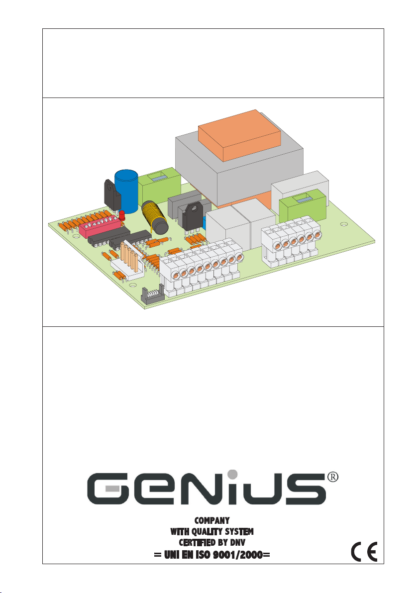
INC rotcennocredocnE
2NC draoblanimretegatlovwoL
3NC draoblanimretegatlovhgiH
4NC rotcennocrevieceR
1RT remmir
1PD hctiws-piDtnemtsujdaretemaraP
1F )02x5(TA51.3rotom/esufrewoP
2F )02x5(TA5.0seiros
DEL DELsutatssecivedytefaS
seccarofesuF
3. BOARD LAY-OUT
ttnemtsujdarewoprotoM
Fig. 1
9
Page 5

4. PREPARATIONS
ATTENTION: To ensure people’s safety, all warnings and instructions in this booklet must be carefully
observed. Incorrect installation or incorrect use of the product could cause serious harm to people.
• Make sure there is an adequate differential switch upstream of the system as specified by current laws, and
install a single-pole thermal breaker on the electric power mains.
• Make sure that an adequate earthing system is available.
• To lay cables, use adequate rigid and/or flexible tubes.
• Always separate 230V~ power cables from low voltage control cables. To avoid any interference, use
separate sheaths.
5. CONNECTIONS AND OPERATION
5.1. CN1 CONNECTOR
The encoder, if supplied, should be connected to this connector. For encoder operation, consult paragraph
7.
ENGLISH
5.2. TERMINAL BOARD CN2
5.2.1. 24 Vdc accessories power supply
Terminals “+ & -”. The accessories 24 Vdc power cables should be connected to these terminals.
Attention:
• The maximum load of the accessories must not exceed 500 mA.
• The output of these terminals is DC - observe the power supply polarity of the accessories.
5.2.2. Open A
Terminals “OPA & -”. Normally open contact. Connect, to these terminals, any pulse generator (e.g. push-
button, key selector, etc..) which, by closing the contact, commands the gate to totally open or close. The
operation of this contact is defined by dip-switch 4 (see paragraph 8).
Attention:
• A total opening pulse always has priority over partial opening.
• To connect several pulse generators, connect the devices in parallel.
5.2.3. Open B
Terminals “OPB & -”. Normally open contact. Connect, to these terminals, any pulse generator (e.g. pushbutton, key selector, etc..) which, by closing the contact, commands the gate to partially open (opens for 8
seconds).
Attention:
• A total opening pulse always has priority over partial opening.
• To connect several pulse generators, connect the devices in parallel.
5.2.4. Photocells
Terminals “FSW & - ”. Normally closed contact. The photocells should be connected to these terminals. The
photocells can operate both as closing safety devices and as opening and closing safety devices. Operation
is defined by dip-switch 5 (see paragraph 8). The status of this input is signalled by LED “FSW”.
Attention: Do not connect other safety devices (i.e. apart from photocells) to these terminals.
5.2.5. Stop
Terminals “STOP & -”. Normally closed contact. Connect, to these terminals, any safety device (push-button,
key selector, etc.) that must stop gate movement, disabling any automatic functions. The gate resumes its
memory-stored cycle only by means of another total opening pulse. The status of this input is signalled by the
“STOP”LED.
Attention:
• To connect several pulse generators, connect the devices in series.
5.2.6. Opening limit switch
Terminals “FCA & COMF”. Normally closed contact. It stops the gate opening movement. The status of this
input is signalled by LED “FCA”.
10
Page 6

5.2.7. Closing limit switch.
Terminals “FCC & COMF”. Normally closed contact. It stops the gate closing movement. The status of this input
is signalled by LED “FCC”.
Attention:
• Both limit-switches must be connected to ensure correct operation of the automated system.
• The COMF terminal must be used ONLY FOR connecting the common contact of the limit-switches.
The magnetic sensor supplied with the operator is designed for rapid connection to the control unit (Fig.2). To
use the sensor with this equipment, cut the connecting terminal from the sensor cable and connect the wires
on the terminal-board as indicated in paragraph 11. To connect the wires, follow the instructions in Fig.3.
Fig. 2
Fig. 3
5.3. TERMINAL BOARD CN3
5.3.1. Gearmotor
Terminals “APM - CHM - COM” (opens - closes - common). Connect the gearmotor power cables to these
terminals, connecting the capacitor between terminals APM and CHM.
5.3.2. Flashing lamp
Terminals “LAMP & N”. Connect the flashing lamp to these terminals. Output of these terminals is 230V~.
Attention: The flashing is not commanded by the control unit but by the flashing lamp.
5.3.3. Power line
Terminals “N & F”. Connect power supply line 230V~ 50Hz to these terminals.
6. INSTALLING THE RADIO CONTROL RECEIVER BOARD
The control unit is designed to house a 5-pin radio-receiver
module. Installation procedure: turn off power and fit the
module on connector CN4 (see Fig.1) on the control unit.
Attention: To avoid damaging the receiver and thus
irreparably compromising its operation, the receiver must
be installed, observing the fitting direction specified in
Fig.4.
Then, follows the radio-receiver instructions for memory-storing
the radio control.
ENGLISH
Fig. 4
11
Page 7

7. ADJUSTING THE OPERATING PARAMETERS
NOITCNUFODNOC
)1(
delbasiDFFO
delbanENO
NOITAREPOANEPO
…/snepO/sesolC/snepOFFO
.../spotS/sesolC/spotS/snepONO
HCTULCCINORTCELE
)2(
ytivitisneS78
hgiHFFOFFO
hgiH-muideMNOFFO
woL-muideMFFONO
woLNONO
All the board’s programmable functions are defined by using dip-switch DP1 (see Fig.1). The various options
are listed in the following tables.
CIGOL 1 2
launaMFFOFFO
esuap
esuap
esuap
ENGLISH
gnisolc
delbasiDFFO
delbanENO
(1)
When the condo function is enabled, the control unit ignores the Open pulses during opening motion.
(2)
Adjustment of the electronic clutch with the Dip-switches is enabled only if the encoder is used (See
sdnoces51,citamotuA
sdnoces02,citamotuA
sdnoces04,citamotuA
ylnognisolcrofelbanEFFO
dnagnineporofelbanE
REDOCNE
NOFFO
FFONO
NONO
NOITAREPOLLECOTOHP
NO
parag. 9).
Attention: Use the dip-switches, only after cutting power. Otherwise, operation of the control unit would
be at risk.
8. ENCODER OPERATION
The control unit is designed for connection to an Encoder (optional item), which guarantees a higher level of
safety. During operation, motor power is directly controlled by the encoder, which detects any obstacles as
the gate moves. If obstacles are encountered, the encoder reverses gate movement for two seconds without
disabling any automatic closing, if enabled. The encoder puts the control unit in STOP state only if it is tripped
twice consecutively. It disables any automatic closure request, because if the encoder intervenes several
times, this means that the obstacle is still there and any automatic devices could be a source of danger. When
the control unit is in STOP state, an OPEN A or B pulse must be supplied to resume normal operation. Encoder
tripping sensitivity is adjusted by dip-switches 7-8 (see parag.7).
Attention: Use of the encoder does not replace the limit-switches, which are compulsory.
Motor power is adjusted in two different ways, according to whether an encoder is connected or not.
!!
! Without encoder: to adjust motor power, use trimmer TR1 (see Fig.1), turning it anti-clockwise to reduce
!!
power and clockwise to increase it. Motor power must be adjusted according to gate dimensions, weight,
and to gate friction during movement.
!!
! With encoder: Motor power is controlled directly by the encoder. To adjust encoder sensitivity, use dip-
!!
switches 7 and 8 as specified in parag.7.
9. ADJUSTING MOTOR POWER
12
Page 8

11. CONNECTION LAY-OUT
12. CONTROL LEDS
sDEL DETHGIL FFO
REWOPderewoptinulortnoC derewoptontinulortnoC
WSFdeppirttonsecivedytefaS deppirtsecivedytefaS
POTSdelbane
ACFeerfhctiwstimilgninepO degagnehctiwstimilgninepO
CCF eerfhctiwstimilgnisolC deg
!!
! Status of LEDs, with powered control unit and gate at rest shown in bold.
!!
tondnammoC delbanednammoC
ENGLISH
Fig. 5
agnehctiwstimilgnisolC
13
Page 9

sesreverdnanoitarepospotS
ytefasgnisolc/gninepO
ehtselbasidti,evitcafI
sdnammocnepO
secived
stratserdnanoitarepospotS
esaelernonoitom
esaelerno
ytefasgnisolc/gninepO
ehtselbasidti,evitcafI
sdnammocnepO
secived
sesreverdnanoitarepospotS
ehtsel
sdnammocnepO
basidti,evitcafI
stratserdnanoitarepospotS
esaelernonoitom
esaelerno
ENGLISH
sesluP
cigolcitamotuA
13. FUNCTION LOGICS
ehtselbasidti,evitcafI
sdnammocnepO
ehtselbasidti,evitcafI
sdnammocnepO
sesluP
cigollaunaM
dnasdnoces8rofsnepO
emitesuapretfasesolc
effeoNnoitarepospotS )2( tnemevometagsesreveR
mmisesolCnoitarepospotS )2( emitesuapsegrahceR )3( emitesuapsegrahceR )3(
retfas
ehtselbasidti,evitcafI
ehtselbasidti,evitcafI
sdnammocnepO
sdnammocnepO
veR
ehtselbasidti,evitcafI
ehtselbasidti,evitcafI
sdnammocnepO
sdnammocnepO
pospotS )2( tceffeoN
es8rofsnepO
esolcdnaetagsnepO
emitesuap
AnepOBnepOpotSsecivedytefasgnisolC
mevomspotS )1( tnemevometagsesreveRnoitarepospotS )2( tceffeoN
sutatsetaG
esuapnonepO yletaidemmisesolCyletaide
gninepO sesrever/tne
desolC
gnisolC sesrever/tnemevomspotS )1( tc
AnepOBnepOpotSsecivedytefasgnisolC
sutatsetaG
desolC snepOsdnoc
nepO sesolCsesolC
14
gninepO sesrever/tnemevomspotS )1( tnemevometagsesreveRnoitare
gnisolC sesrever/tnemevomspotS )1( tceffeoNnoitarepospotS )2( tnemevometagsesre
(1) The behaviour of Open A push-button is defined by Dip-switch 4 - see parag.7.
(2) The Stop pulse stops gate operation and disables all selected automatic functions. An Open A pulse is necessary to resume the memory-stored cycle.
(3) If the safety device is engaged when the programmed pause time elapses, when it is released, the control unit resumes counting the programmed pause time.
Page 10

Le descrizioni e le illustrazioni del presente manuale non sono impegnative. GENIUS si riserva il diritto, lasciando inalterate le caratteristiche essenziali
dell’apparecchiatura, di apportare in qualunque momento e senza impegnarsi ad aggiornare la presente pubblicazione, le modifiche che essa ritiene
convenienti per miglioramenti tecnici o per qualsiasi altra esigenza di carattere costruttivo o commerciale.
The descriptions and illustrations contained in the present manual are not binding. GENIUS reserves the right, whils leaving the main features of the equipments
unaltered, to undertake any modifications to holds necessary for either technical or commercial reasons, at any time and without revising the present
publication.
Les descriptions et les illustrations du présent manuel sont fournies à titre indicatif. GENIUS se réserve le droit d’apporter à tout moment les modifications qu’elle
jugera utiles sur ce produit tout en conservant les caractéristiques essentielles, sans devoir pour autant mettre à jour cette publication .
Las descripciones y las ilustraciones de este manual no comportan compromiso alguno. GENIUS se reserva el derecho, dejando inmutadas las características
esenciales de los aparatos, de aportar, en cualquier momento y sin comprometerse a poner al día la presente publicación, todas las modificaciones que
considere oportunas para el perfeccionamiento técnico o para cualquier otro tipo de exigencia de carácter constructivo o comercial.
Die Beschreibungen und Abbildungen in vorliegendem Handbuch sind unverbindlich. GENIUS behält sich das Recht vor, ohne die wesentlichen Eigenschaften
dieses Gerätes zu verändern und ohne Verbindlichkeiten in Bezung auf die Neufassung der vorliegenden Anleitungen, technisch bzw, konstruktiv /
kommerziell bedingte Verbesserungen vorzunehmen.
Timbro rivenditore: / Distributor’s stamp: / Timbre de l’agent: /
Sello del revendedor: / Fachhändlerstempel:
GENIUS S.p.A.
Via Padre Elzi, 32
24050 - Grassobbio
BERGAMO-ITALY
tel. 0039.035.4242511
fax. 0039.035.4242600
info@geniusg.com
www.geniusg.com
I0438 Rev.1
 Loading...