

Page 1
S
S
E
E
R
R
VII
V
C
C
E
E
G
G
KYE SYSTEMS CORP.
UII
U
D
D
E
E
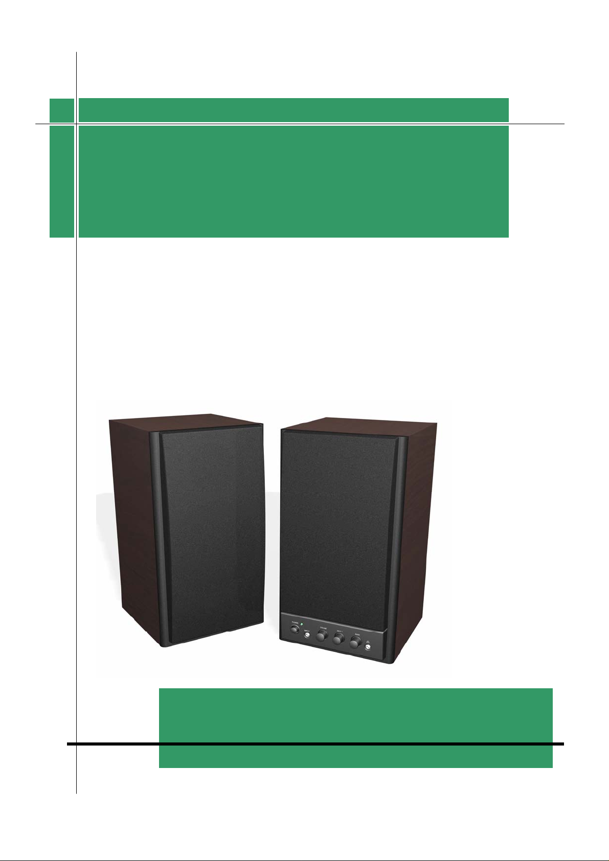
SSPP--HHFF11225500XX
Version:1.0
Total 14 Pages (Cover Page included)
Page 2
s
ervice
Guide
Revision History
Version Date Changes
SP-HF1250X
1.0
Official Release
Version: 1.0 Page 1/13
Page 3

s
ervice
SP-HF1250X
Guide
Table of Contents
Revision History………………………………………………………………………..1
Table of Contents………………………………………………… ………….2
Getting Started………………………………………………… ……….……………....3
Conventions Used in this Guide………………… ………...……………….3
Safety Precautions……………………………… ………………...………..3
Chapter1. How to Handle Defective Returns………………… ……………………….4
1.1 Overview……………………………………………………………….4
1.2 Problems………………………………………………………………..5
1.2.1 Power LED (indicator) Unlight…………………...……………......6
1.2.2 Does not work or one channel no sound……………………….…..7
1.2.3 Noise……………………………………………………………….7
Chapter2. Specifications………………………………………………………………..8
Chapter3. Block Diagram……………………………………………………………....9
Chapter4. Exploded View……………………………………………………………...10
Chapter5. Part List…………………………………………………………………….11
Chapter6. Important Notes…………………………………………………………....12
6.1 Packing Requirement for sending the PCB Assembly by post……….…12
6.2 Short of Spare Parts while Repairing a Speaker System…………….….12
Chapter7. Circuit Schematic……………………………………………………………13
Version: 1.0 Page 2/13
Page 4
s
ervice
Guide
Getting Started
Conventions Used in this Guide
Pay Special Attention: Instructions that are important to
Attention
remember and may prevent mistakes.
Caution: Information that, if not followed, may result in
damage to the product.
SP-HF1250X
Safety Precautions
The following precautions should be observed in handling the speaker described in this guide:
Place the speakers on a flat , level and stable surface.
Do not place the speakers in environments subject to mist, smoke, vibration, excessive dust,
salty or greasy air, or other corrosive gases and fumes.
Do not drop or jolt the speakers.
Do not allow anything to drop into the subwoofer case through its ventilator, as it could
result in fatal electric shock or fire.
Place the unit far enough from other equipments for good heat dissipation.
Disconnect the AC power cord from the AC outlet before performing any maintenance on the
speakers.
Do not perform any maintenance with wet hand.
Prevent foreign substance, such as water, other liquids or chemicals, from entering the
speakers while performing maintenance procedures on the speakers.
Version: 1.0 Page 3/13
Page 5
s
ervice
p
Guide
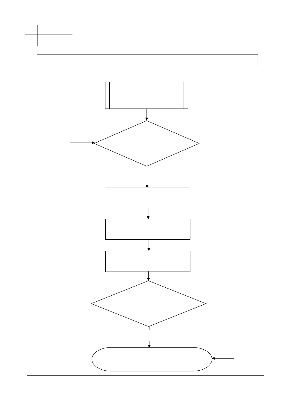
Chapter 1. How to Handle Defective Returns
1.1 Overview
Receiving Defective
Speakers
from Customers
SP-HF1250X
Functioning NG
Verifying problems&
Proceeding necessary tests
Functioning NG
Analyzing possible
Malfunction causes
Deciding & proceeding
the rectification methods
Replacing necessary
Defective parts
Functioning OK
Proceeding tests
To verify if the speaker is
functioning normally
Functioning OK
Return the speakers with
er repackaging to customers
Pro
Version: 1.0 Page 4/13
Page 6

s
ervice
Guide
1.2 Problems
Item Problem descriptions
1.2.1 Power LED (indicator) unlight
1.2.2 Does not work or one channel no sound
1.2.3 Noise
SP-HF1250X
Version: 1.0 Page 5/13
Page 7

s
ervice
Guide
SP-HF1250X
Please follow the numbered sequence marked withing parenthesis given in individual
Flow chart, in that this is the best-recommended sequence to rectify the problems.
Attention
1.2.1 Power LED (indicator) unlight
Problem
Analyze and
Identify the
Causes
Solutions
Secondary wire
Of transformer is
Disconnected or
defective
Power LED (indicator) unlight
Diode D1.2.5.6
burnt
Resolder or replace defective component(s)
Defective power
Switch or LED
Version: 1.0 Page 6/13
Page 8

s
ervice
r
r
d
Guide
1.2.2 Does not work jor jone channel no sound
SP-HF1250X
Problem
Analyze and
Identify the
Causes
Solutions
Defective
Audio cable
Replace
Audio cable
Does not work or
One channel no sound
Broken o
Short circuit
Check solde
Points on PCB
And resolder
defective one(s)
Defective IC
Check and replace
Defective IC
1.2.3 Noise
Problem
Analyze and
Identify the
Causes
Solutions
Component(s) aroun
IC is/are defective
Check and replace
defective component(s)
Noise
Defective VR Defective IC
Replace
Defective VR
Replace defective IC
Version: 1.0 Page 7/13
Page 9

s
ervice
SP-HF1250X
Guide
Chapter 2. Specifications
No. DESCRIPTION UNIT NOMINAL LIMIT
1 INPUT SENSITIVITY AT 10% mV 340 340+/-50
2 DISTORTION AT 1 KHz % 0.15 <0.5
3 OUTPUT POWER AT 10% DISTORTION W 18 18+/-1
4 S/N RATIO dB 74 >60
5 CHANNEL SEPARATION dB 49 >40
6 FREQUENCY RESPONSE
(DOWN 3dB) (LOW)
(HIGH)
7 HUM LEVEL (AT VOL. MIN.)
HUM LEVEL (AT VOL. MAX.)
8 OPERATING VOLTAGE MAX.253VAC
MIN. 207VAC
TEST CONDITION:
1) LOAD 4Ω
Hz
KHz
mV
mV
20
20
1
2.5
+/-10%
+/-10%
<3
<5
2)RATED POWER 1 W
VOLUME AT MAX.
Version: 1.0 Page 8/13
Page 10

s
ervice
Guide
Chapter 3. Block Diagram
SP-HF1250X
AC IN
R.CH
SPEAKER
R.OUT
L.OUT
POWER
AMPLIFIER
POWER SWITCH
L.CH
SPEAKER
TRANSFORMER
FILTER
VOLUME
CONTROL
R.IN
L.IN
AUDIO INPUT
Version: 1.0 Page 9/13
Page 11

s
ervice
Guide
Chapter 4. Exploded View
SP-HF1250X
Version: 1.0 Page 10/13
Page 12

s
ervice
Guide
Chapter 5. Part List
SP-HF1250X
Ref. No.
1
2
3
4
5
6
7
8
9
10
11
12
13
14
15
Description
AC Cord, 5.9’,Black Color 250V/2.5A 2PIN,CE
Output Panel, SP-HF1250X, Black Color
RCA, Yellow Color
Input Panel, SP-HF1250X, Black Color
Rear board, SP-HF1250X, Black Color 9T MDF
Transformer, 230V, 8V/250mA
Function PCB Assembly, SP-HF1250X, 94V0
Wrap board(L) SP-HF1250X, 12T MDF
Speaker, 1” 4Ω,15W
Speaker, 5.25” 4Ω, 20W, Magnetically Shielded
Screw, HSA3.5x16mm, Black
Cloth frame(L), SP-HF1250X, Black Color
Badge, SP-HF1250X, Silver Color ABS
Knob, SP-HP1250X, Silver Color HIPS
Button, SP-HF1250X, Silver Color HIPS
Control PCB Assembly, SP-HF1250X, 94V0
Screw, PWPA2.6x10mm, Black
Rubber Foot One side tape glue
Screw, PPB 3x8mm, Black
Nut M4, Black Color
Screw, BPA 3.5x20mm, Black
Screw, PWPB M4x16mm, Black
Screw, BPA 3x12mm, Black
Screw, BPA 3x10mm, Black
Cloth frame(R), SP-HF1250X, HIPS Black Color
Wrap board(R),SP-HF1250X, 12T MDF
Terminal board, SP-HF1250X, Black Color HIPS
RS Part No. Mfr’s Part No.
17U2115125100-0
1
0114HIPS00007-0
1
2021184084101-0
2
0114HIPS00021-0
1
1003040910200-0
1
2225400020001-0
1
180103594V001-0
1
9401040012500-0
16
17
3
0820150401312-0
Version: 1.0 Page 11/13
Page 13

18
1
19
20
21
22
23
24
25
26
27
084020045A112-0
3
4102H35016A06-0
2
9101086078093-0
1
01070ABS03001-
01
0107HIPS00001-0
1
0107HIPS81001-0
2
180303594V001-0
1
4102N26010A02-0
1
4311020050010-0
1
4101P30008B02-0
1
Version: 1.0 Page 12/13
4107300402020-0
Page 14

1
4102B35020A02-0
1
4101N40060B02-0
1
4102B30012A02G
01
4102B30010A02-0
1
9101086078105-0
1
9401030011760-0
1
0114HIPS00017-0
1
Version: 1.0 Page 13/13
Page 15

s
ervice
SP-HF1250X
Guide
Chapter 6. Important Notes
6.1 Packing requirement for sending the PCB assembly by post
PCB assembly is a kind of sophisticated electronic circuit board. Well packing
Will be required when sending them by post.
*Some sophisticated IC components are mounted on the PCB assembly, hence
it is necessary to pack each PCB assembly with a separate static protecting bag,
in order to avoid static electricity.
*Reliable external packing is also very important when sending the PCB assembly
by post, in that it would avoid unnecessarily lost or damage.
6.2 Short of spare parts while repairing a speaker system
If you are short of spare parts when you have some spesker systems waiting to
be repaired,it would be recommended to take the necessary parts from one
Speaker system,so that you may haye the as many speaker systems
Version: 1.0 Page 14/13
Page 16

s
ervice
Guide
Chapter 7. Circuit schematic
SP-HF1250X
Version: 1.0 Page 15/13
 Loading...