

Page 1
S
S
E
E
R
R
VII
V
C
C
E
E
G
G
KYE SYSTEMS CORP.
UII
U
D
D
E
E
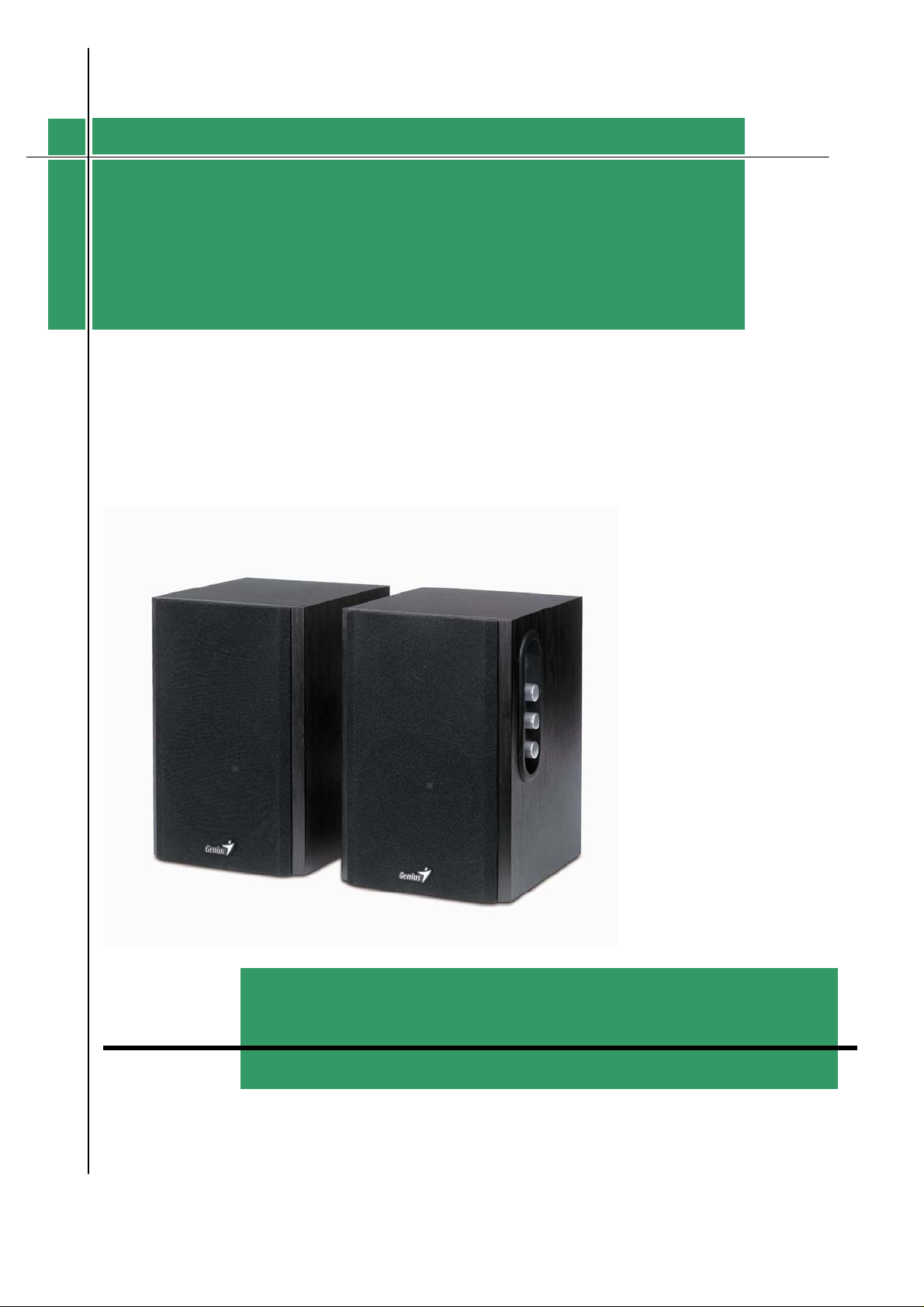
SSPP--HHFF11225500AA
Version:1.0
Total 16 Pages (Cover Page included)
Page 2
y
ervice
s
Guide
Revision Histor
SP-HF1250A
Version Date Changes
1.0
Official Release
Version: 1.0 Page 1/15
Page 3

ervice
s
Guide
SP-HF1250A
Table of Contents
Revision History……………………………………………………………………..1
Table of Contents………………………………………………… ………….2
Getting Started………………………………………………… ……….……………....3
Conventions Used in this Guide………………… ………...……………….3
Safety Precautions……………………………… ………………...………..3
Chapter1. How to Handle Defective Returns………………… ……………………….4
1.1 Overview……………………………………………………………….4
1.2 Problems………………………………………………………………..5
1.2.1 Power LED (indicator) Unlighted………………...……………......6
1.2.2 Does not work or one channel no sound……………………….…..7
1.2.3 Noise……………………………………………………………….7
Chapter2. Specifications………………………………………………………………..8
Chapter3. Block Diagram……………………………………………………………....9
Chapter4. Exploded View…………………………………………………………….…10-11
Chapter5. Part List……………………………………………………………………..12-13
Chapter6. Important Notes…………………………………………………………....14
6.1 Packing Requirement for sending the PCB Assembly by post……….…14
6.2 Short of Spare Parts while Repairing a Speaker System…………….….14
Chapter7. Circuit Schematic……………………………………………………………15
Version: 1.0 Page 2/15
Page 4
ervice
s
Guide
Getting Started
Conventions Used in this Guide
Pay Special Attention: Instructions that are important to
Attention
remember and may prevent mistakes.
Caution: Information that, if not followed, may result in
damage to the product.
SP-HF1250A
Safety Precautions
The following precautions should be observed in handling the speaker described in this guide:
Place the speakers on a flat level and stable surface.
Do not place the speakers in environments subject to mist, smoke, vibration, excessive dust, salty
or greasy air, or other corrosive gases and fumes.
Do not drop or jolt the speakers.
Do not allow anything to drop into the subwoofer case through its ventilator, as it could result
in fatal electric shock or fire.
Place the unit far enough from other equipments for good heat dissipation.
Disconnect the AC power cord from the AC outlet before performing any maintenance on the
speakers.
Do not perform any maintenance with wet hand.
Prevent foreign substance, such as water, other liquids or chemicals, from entering the speakers
while performing maintenance procedures on the speakers.
Version: 1.0 Page 3/15
Page 5
p
ervice
s
Guide
Chapter 1. How to Handle Defective Returns
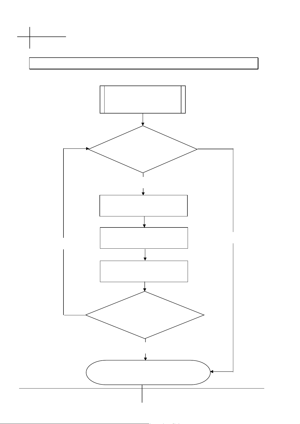
1.1 Overview
Receiving Defective
Speakers
from Customers
SP-HF1250A
Functioning NG
Verifying problems&
Proceeding necessary tests
Functioning NG
Analyzing possible
Malfunction causes
Deciding & proceeding
the rectification methods
Replacing necessary
Defective parts
Functioning OK
Proceeding tests
To verify if the speaker is
functioning normally
Pro
Functioning OK
Return the speakers with
er repackaging to customers
Version: 1.0 Page 4/15
Page 6

ervice
s
Guide
1.2 Problems
Item Problem descriptions
1.2.1 Power LED (indicator) unlighted
1.2.2 Does not work or one channel no sound
1.2.3 Noise
SP-HF1250A
Version: 1.0 Page 5/15
Page 7

ervice
s
Guide
SP-HF1250A
Please follow the numbered sequence marked within parenthesis given in individual
Flow chart, in that this is the best-recommended sequence to rectify the problems.
Attention
1.2.1 Power LED (indicator) unlighted
Problem
Analyze
and
Identify
the Causes
Solutions
Secondary wire Of
transformer is
Disconnedcted of
defective
Power LED (indicator)unlighted
CheckD1.2
.3.4
Check
LED
Resolder or replace defective component(s)
Defective power
Switch
Version: 1.0 Page 6/15
Page 8

r
t
r
(s)
d
ervice
s
SP-HF1250A
Guide
1.2.2 Does not work or one channel no sound
Problem
Analyze
and
Identify the
Causes
Solutions
1.2.3 Noise
Defective
Audio cable
Replace
Audio cable
Does not work or
Broken o
Short circui
Check solde
Points on PCB
And resolder
Defective IC
(TDA2030A)
Check and replace
Defective IC
(TDA2030A)
defective one
Problem
Analyze and
Identify the
Causes
Solutions
Noise
Component(s) aroun
IC is/are defective
Check and replace
defective component(s)
Defective
Replace
Defective VR
VR
Defective IC
(TDA2030A)
Replace defective IC
(TDA2030A)
Version: 1.0 Page 7/15
Page 9

ervice
s
Guide
Chapter 2. Specifications
Satellite
SP-HF1250A
No. DESCRIPTION
1. FRONT OUTPUT POWER @THD 10% W 19.8 19.8
2
SENSITIVITY(1KHz)@RATED O/P
POWER
3 SENSITIVITY(1KHz)@1W O/P POWER mV 130 130
4 MAX INPUT LEVEL@1%
5 FREQUENCY RESPONSE(1KHz=0dB)
50Hz dB -3 -3
1K dB 0 0
20K dB -3 -3
6 S/N @RATED O/P POWER dB 80 80
7 CHANNEL UNBALANCE @REF O/P
POWER
8 CHANNEL SEPARATION(ONE
CHANNEL IN; OTHER CHANNEL INPUT
SHORTING)
9 HUM NOISE (VR MAX)
(VOLUME MAX; INPUT SHORTING)
10 HUM NOISE (VR MIN)
(VOLUME MIN. INPUT SHORTING)
THD mV 500 500
UNIT NOMINAL LIMIT
FR FL
mV 640 640
dB 0.3 0.3
dB 59 59
mV 0.9 0.9
mV 0.2 0.2
≥19
±50
±20
±40
±0.5
±0.5
±0.5
≥60
≤0.5
≥45
≤5
≤3
Version: 1.0 Page 8/15
Page 10

ervice
s
Guide
Chapter 3. Block Diagram
SP-HF1250A
Version: 1.0 Page 9/15
Page 11

Subwoofer
s
Guide
ervice
Chapter 4. Exploded View
SP-HF1250A
Version: 1.0 Page 10/15
Page 12

ervice
s
Guide
Chapter 4. Exploded View
SATELLITE
3
SP-HF1250A
9
8
7
6
5
4
2
1
10
11
12
Version: 1.0 Page 11/15
Page 13

ervice
s
Guide
Chapter 5. Part List
Subwoofer
SP-HF1250A
Ref. No.
1
2
3
4
5
6
7
8
9
10
11
12
13
14
15
16
17
18
19
20
21
22
23
24
25
26
27
28
29
Description
Badge, L34xW16.9xT1.8 AL
Cloth , 2104 BLACK
Frame 6.0MDF
Speaker 4''4Ω 20W
Speaker 1″8Ω15W
Wood-box, 9T MDF PVC F-517-3c
Female Button
Function PCBA , Volume
Heat sink, AL Silver
Screw BAΦ3.0x12 ,
Bracket L15*W10*T1.0
Screw M3x8 , zincification Black Color
Back Board 9.0MDF
Paper Tube IDΦ35*ODΦ39*70L
Screw BAΦ3.5x20,
Power Switch
Screw PAΦ3.0x10,
AL Board, Black Color
PCBA
Cable Fastner 4K-4
PCBA
IC ST TDA2030A
Nut whit flange M4,
Tra ns f o r m er,
Screw ,M4*16 zincification Black Color
Knob,HIPS Silver Color
Deco ring HIPS, black coler
Screw BAΦ3.0x12 ,
Rubber foot ,black color
Screw BAΦ3.5x16 ,
zincification Black Color
zincification Black Color
zincification Black Color
zincification Black Color
230V 50HZ
zincification Black Color
zincification Black Color
RS Part No. Part No.
016800958
014700618
034610688
010402978
010403028
035201968
027400148
033003428
017300478
017903258
021000378
017903228
034903138
015501168
017903248
011000118
017903278
034201308
033003478
027405578
033003488
019300238
008901148
017903238
026900958
026300698
017903258
015103558
017903268
Version: 1.0 Page 12/15
Page 14

ervice
s
Guide
Chapter 5. Part List
Satellite
SP-HF1250A
Ref. No.
1
2
3
4
5
6
7
8
9
10
11
12
Description
Badge, L34xW16.9xT1.8 AL
Cloth , 2104 BLACK
Frame 6.0MDF
Speaker 4''4Ω 20W
Screw BAΦ3.0x12 ,
Speaker 1″8Ω15W
Female Button
Wood-box, 9T MDF PVC F-517-3c
Paper Tube IDΦ35*ODΦ39*70L
Back board, 9.0MDF
Rubber foot ,black color
Screw BAΦ3.5x16 ,
zincification Black Color
zincification Black Color
RS Part No. Part No.
016800958
014700618
034610688
010402978
017903258
010403028
027400148
033901658
015501168
034903148
015103558
017903268
Version: 1.0 Page 13/15
Page 15

ervice
s
Guide
Chapter 6. Important Notes
6.1 Packing requirement for sending the PCB assembly by post
PCB assembly is a kind of sophisticated electronic circuit board. Well packing
Will be required when sending them by post.
*Some sophisticated IC components are mounted on the PCB assembly, hence
it is necessary to pack each PCB assembly with a separate static protecting bag,
in order to avoid static electricity.
*Reliable external packing is also very important when sending the PCB assembly
by post, in that it would avoid unnecessarily lost or damage.
SP-HF1250A
6.2 Short of spare parts while repairing a speaker system
If you are short of spare parts when you have some spesker systems waiting to
be repaired,it would be recommended to take the necessary parts from one
Speaker system,so that you may haye the as many speaker systems
Version: 1.0 Page 14/15
Page 16

ervice
s
Guide
Chapter 7. Schematic Diagram
SP-HF1250A
SPEAKER
R-OUT
R
1
2
R4
1 OHM
C3
M/224
4
22K
C/101
U1-A
-
+
R2
C1
IC-TDA2030
2
1
C7
M/104
1K
22K
R33
R35
R3
1K
C2
22uF/25V
+
R1
22K
1K
22K
R36
R34
10 OHM
R29
100uF/16V
+
C21
1
U6-A
IC-4558
+
-
2
3
4.7uF/25V
+
C15
IC-4558
6
100uF/16V
C22
7
-
4.7uF/25V
C16
R13
4
U3-A
+
-
IC-TDA2030
2
1
C14
M/104
10 OHM
R30
+
U6-B
+
5
470
+
R47
SPEAKER
L-OUT
L
1
2
1 OHM
C10
M/224
22K
C/101
C8
R11
1K
C9
R12
22uF/25V
+
22K
R10
4 8
U6-C
IC-4558
4 8
U5-C
IC-4558
+
C37
100uF/16V
R43
D6
2K
+
C35
100uF/25V
IC-TDA2030
IC-TDA2030
IC-TDA2030
+VCC
IC-TDA2030
C33
+
C31
R48
1K
+VCC
D5
5.1V
+
C39
22uF/16V
4700uF/25V
D2
IN5401
D1
IN5401
C/104
IN5401
IN5401
C38
+
100uF/16V
R44
D7
9.1V
9.1V
2K
+
C36
100uF/25V
3 5
U4-B
3 5
U3-B
3 5
U2-B
-VCC
3 5
U1-B
C/104
C34
+
C32
D4
D3
4700uF/25V
1
2
456
R40
4.7K
VR3-B
VR1-B
456
C27
M/473
C30
3
P3
VR2-B
R41
C28
2.7K
M/124
R42
M/103
5.6K
1234567
8
8
C25
M/222
123
P1
P2
123
123
C23
M/473
LED
123
VR1-A
VR2-A
R38
C24
M/124
C26
M/103
C29
2.7K
M/222
R39
5.6K
456
4
567
R37
4.7K
VR3-A
4.7uF/25V
+
C17
1
U5-A
IC-4558
+
2
3
C40
4.7uF/25V
L
L
R
R
8
12345
6
7
P7
P6
8
P8
12345
2
1
PHONE
1
JK/5P/PHONE
2
RCA2
1234567
L
R
1
RCA1-A
4.7uF/25V
+
C19
7
U5-B
30K
30K
IC-4558
C20
C18
-
R23
10K
+
L
3
+
-
6
5
R24
R28
C/101
C/101
R26
10K
+
C41
4.7uF/25V
R
4
2
RCA1-B
Version: 1.0 Page 15/15
 Loading...