


Operator's Manual
Serial Number Range
GS™-1432m
from GS32mD-101
ANSI/CSA
North America
South America
Asia
GS™-1932m
with
Maintenance
Information
Original Instructions
First Edition
First Printing
Part No. 1307419GT

Operator's Manual First Edition • First Printing
GS™-1432m • GS™-1932m Part No. 1307419GT
Front Matter
Contents
Introduction ........................................................... 1
Symbol and Hazard Pictorials Definitions ............. 5
General Safety ...................................................... 8
Personal Safety ................................................... 14
Work Area Safety ................................................ 15
Legend ................................................................ 23
Controls ............................................................... 24
Inspections .......................................................... 27
Operating Instructions ......................................... 42
Transport and Lifting Instructions ....................... 56
Maintenance ....................................................... 61
Specifications ...................................................... 63
Copyright © 2020 Terex Corporation
First Edition: First Printing, February 2021
Genie is a registered trademark of Terex South Dakota, Inc. in
the U.S.A. and many other countries. “GS” is a trademark of
Terex South Dakota, Inc.
These machines comply with
ANSI/SAIA A92.20
CAN/CSA B354.6
First Edition • First Printing Operator's Manual
Introduction
Part No. 1307419GT GS™-1432m • GS™-1932m 1
Introduction
About this manual
Genie appreciates your choice of our machine for
your application. Our number one priority is user
safety, which is best achieved by our joint efforts.
This book is an operation and daily maintenance
manual for the user or operator of a Genie
machine.
This manual should be considered a permanent
part of your machine and should remain with the
machine at all times. If you have any questions,
contact Genie.
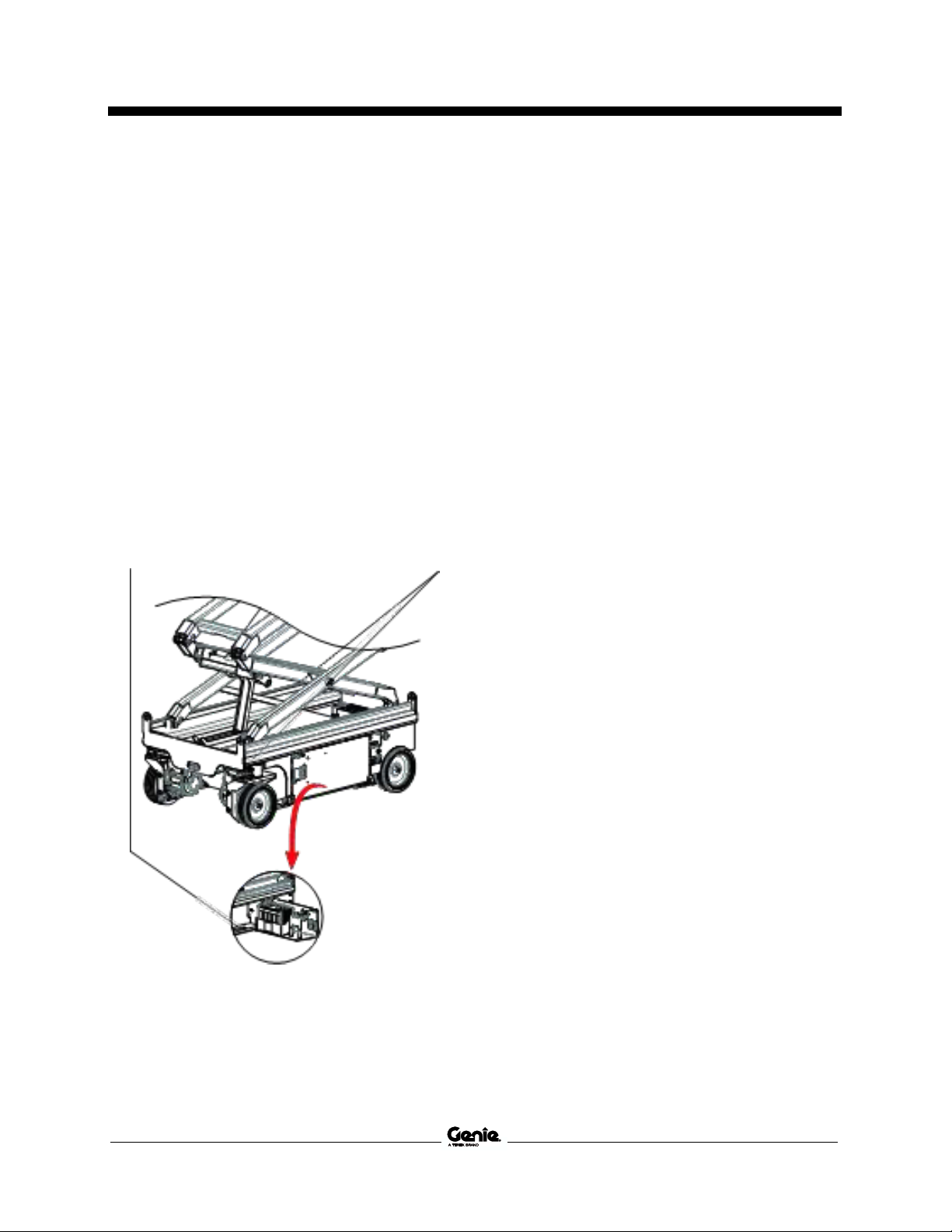
Product Identification
The machine serial number is located on the serial
label.
Serial label located in
charger tray
Serial number stamped on
chassis
Intended Use and Familiarization
Guide
The intended use of this machine is to lift
personnel, including tools, and materials to an
aerial work site. Before operating the machine, it’s
the operator’s responsibility to read and
understand this familiarization guide.
Each person must be trained to operate a
Mobile Elevating Work Platform (MEWP).
Familiarization with the MEWP must be given
to each person who is authorized, competent
and trained.
Only trained and authorized personnel should
be permitted to operate the machine.
The operator is responsible to read,
understand, and obey the manufacturer’s
instructions and safety rules provided in the
Operator’s Manual.
The Operator’s Manual is located in the
manual storage container, at the platform.
For specific product applications, see
Contacting The Manufacturer.

Operator's Manual First Edition • First Printing
Introduction
2 GS™-1432m • GS™-1932m Part No. 1307419GT
Platform controls symbology and related
machine movement:
Lift function enable button
Drive function enable button
Platform up/down (when lift function
selected)
Drive forward/reverse (when drive
function selected)
Steer right/left (when drive function
selected)
Area of operation, indoor use button
Area of operation, outdoor use button
Ground controls symbology and related
machine movement:
Lift function enable button
Platform up/down button
Sequential functions and movement:
Drive and steer.
Interlocked functions:
Elevated drive speed.
Elevated drive in an off-level condition.
All platform and ground controls.
Limitations of use:
The intended use of this machine is to lift
personnel, including tools, and materials to an
aerial work site.
Do not elevate the platform unless the machine
is on firm level ground.

First Edition • First Printing Operator's Manual
Introduction
Part No. 1307419GT GS™-1432m • GS™-1932m 3
Bulletin Distribution and Compliance
Safety of product users is of paramount
importance to Genie. Various bulletins are used by
Genie to communicate important safety and
product information to dealers and machine
owners.
The information contained in the bulletins is tied to
specific machines using the machine model and
serial number.
Distribution of bulletins is based on the most
current owner on record along with their
associated dealer, so it is important to register
your machine and keep your contact information
up to date.
To ensure safety of personnel and the reliable
continued operation of your machine, be sure to
comply with the action indicated in a respective
bulletin.
To view any open bulletins for your machine, visit
us on the web at www.genielift.com.
Contacting the Manufacturer
At times it may be necessary to contact Genie.
When you do, be ready to supply the model
number and serial number of your machine, along
with your name and contact information. At
minimum, Genie should be contacted for:
Accident reporting
Questions regarding product applications and
safety
Standards and regulatory compliance information
Current owner updates, such as changes in
machine ownership or changes in your contact
information. See Transfer of Ownership, below.
Transfer of Machine Ownership
Taking a few minutes to update owner information
will ensure that you receive important safety,
maintenance and operating information that
applies to your machine.
Please register your machine by visiting us on the
web at www.genielift.com or by calling us toll free
at 1-800-536-1800.
Operator's Manual First Edition • First Printing
Introduction
4 GS™-1432m • GS™-1932m Part No. 1307419GT
Danger
Failure to obey the instructions and
safety rules in this manual will result
in death or serious injury.
Do Not Operate Unless:
You learn and practice the principles of safe
machine operation contained in this operator’s
manual.
1 Avoid hazardous situations.
Know and understand the safety rules
before going on to the next section.
2 Always perform a pre-operation inspection.
3 Always perform function tests prior to use.
4 Inspect the workplace.
5 Only use the machine as it was intended.
You read, understand and obey the
manufacturer’s instructions and safety rules—
safety and operator’s manuals and machine
decals.
You read, understand and obey employer’s
safety rules and worksite regulations.
You read, understand and obey all applicable
governmental regulations.
You are properly trained to safely operate the
machine.
Safety Sign Maintenance
Replace any missing or damaged safety signs.
Keep operator safety in mind at all times. Use mild
soap and water to clean safety signs. Do not use
solvent-based cleaners because they may
damage the safety sign material.
Hazard Classification
Decals on this machine use symbols, color coding,
and signal words to identify the following:
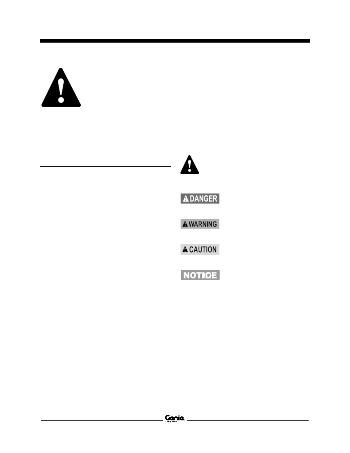
Safety alert symbol—used to alert
you to potential personal injury
hazards. Obey all safety
messages that follow this symbol
to avoid possible injury or death.
Indicates a hazardous situation
which, if not avoided, will result in
death or serious injury.
Indicates a hazardous situation
which, if not avoided, could result
in death or serious injury.
Indicates a hazardous situation
which, if not avoided, could result
in minor or moderate injury.
Indicates a property damage
message.

First Edition • First Printing Operator's Manual
Symbol and Hazard Pictorials Definitions
Part No. 1307419GT GS™-1432m • GS™-1932m 5
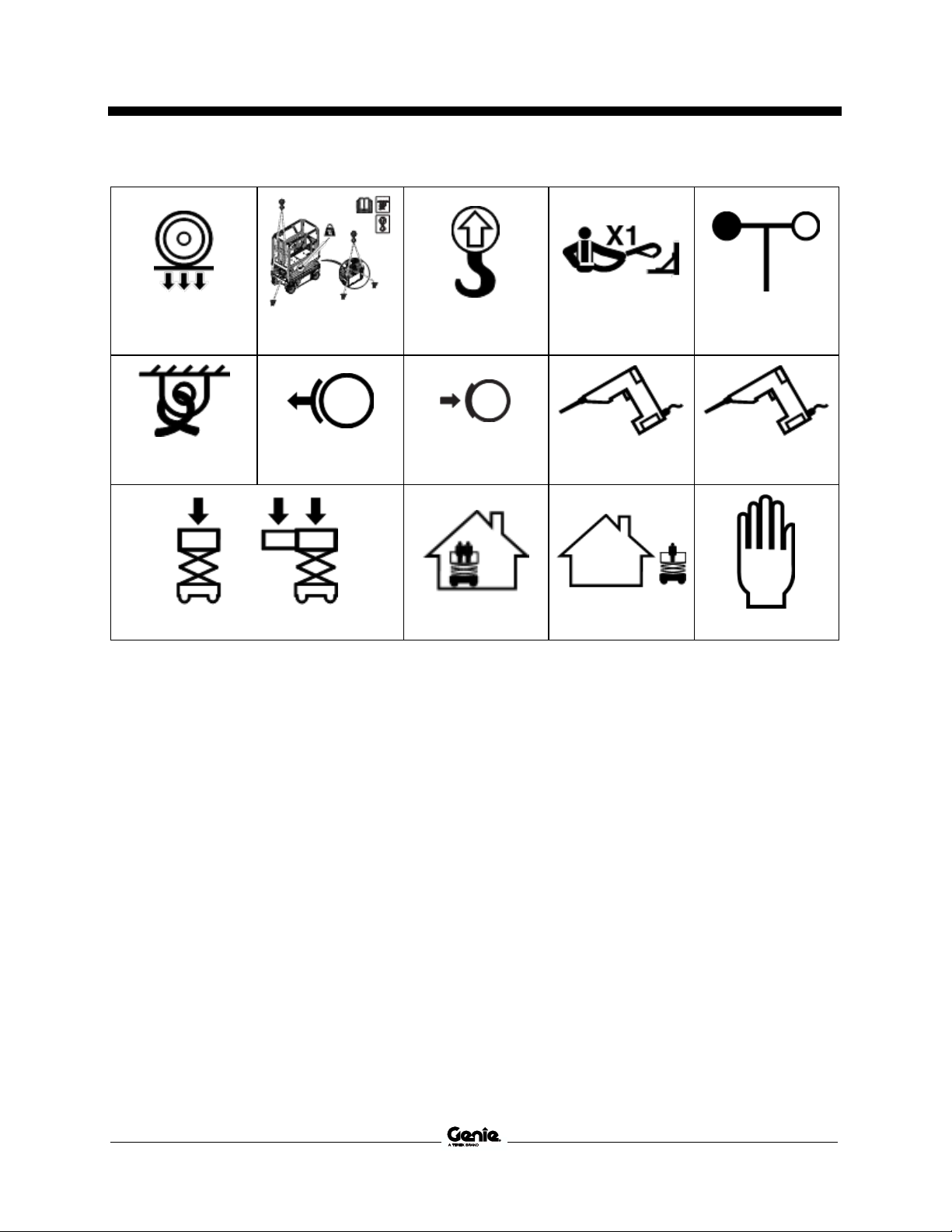
Symbol and Hazard Pictorials Definitions
Read the operator’s
manual
Read the service
manual
Crush hazard
Crush hazard
Collision hazard
Tip-over hazard
Tip-over hazard
Tip-over hazard
Tip-over hazard
Electrocution hazard
Electrocution hazard
Explosion hazard
Fire hazard
Burn hazard
Skin injection hazard

Operator's Manual First Edition • First Printing
Symbol and Hazard Pictorials Definitions
6 GS™-1432m • GS™-1932m Part No. 1307419GT
Engage safety arm
Keep away from
moving parts
Keep clear of tires
Move machine to
level ground
Close chassis tray
Lower the platform.
Platform overloaded
Maintain required
clearance
Access by trained
and authorized
personnel only
Use a piece of
cardboard or paper
to search for leaks
Batteries used as
counterweights
Chock the wheels
No smoking
Grounded AC
3-wire only
Replace damaged
wires and cords
First Edition • First Printing Operator's Manual
Symbol and Hazard Pictorials Definitions
Part No. 1307419GT GS™-1432m • GS™-1932m 7
Wheel load
Lifting & tie down
instructions
Lifting point
Lanyard anchorage
points
Wind speed
Tiedown
Release brakes
Engage brake
Pressure rating for
air line to platform
Voltage rating for
power to platform
Maximum capacity
Indoor
Outdoor
Manual force
Operator's Manual First Edition • First Printing
General Safety
8 GS™-1432m • GS™-1932m Part No. 1307419GT
General Safety
First Edition • First Printing Operator's Manual
General Safety
Part No. 1307419GT GS™-1432m • GS™-1932m 9
Operator's Manual First Edition • First Printing
General Safety
10 GS™-1432m • GS™-1932m Part No. 1307419GT
First Edition • First Printing Operator's Manual
General Safety
Part No. 1307419GT GS™-1432m • GS™-1932m 11
Operator's Manual First Edition • First Printing
General Safety
12 GS™-1432m • GS™-1932m Part No. 1307419GT

First Edition • First Printing Operator's Manual
General Safety
Part No. 1307419GT GS™-1432m • GS™-1932m 13

Operator's Manual First Edition • First Printing
Personal Safety
14 GS™-1432m • GS™-1932m Part No. 1307419GT
Personal Safety
Personal Fall Protection
Personal fall protection equipment (PFPE) is not
required when operating this machine. If PFPE is
required by job site or employer rules, the
following shall apply:
All PFPE must comply with applicable
governmental regulations and must be inspected
and used in accordance with the manufacturer’s
instructions.
First Edition • First Printing Operator's Manual
Work Area Safety
Part No. 1307419GT GS™-1432m • GS™-1932m 15
Work Area Safety
Electrocution Hazards
This machine is not electrically insulated and will
not provide protection from contact with or
proximity to electrical current.
Obey all local and
governmental
regulations regarding
required clearance from
electrical power lines. At
a minimum, the required
clearance contained in
the chart below must be
followed.
Line Voltage
Required Clearance
0 to 50KV
10 ft
3.05 m
50 to 200KV
15 ft
4.60 m
200 to 350KV
20 ft
6.10 m
350 to 500KV
25 ft
7.62 m
500 to 750KV
35 ft
10.67 m
750 to 1000KV
45 ft
13.72 m
Allow for platform movement, electrical line sway
or sag, and beware of strong or gusty winds.
Keep away from the
machine if it contacts
energized power lines.
Personnel on the ground
or in the platform must
not touch or operate the
machine until energized
power lines are shut off.
Do not operate the machine during lightning or
storms.
Do not use the machine as a ground for welding.
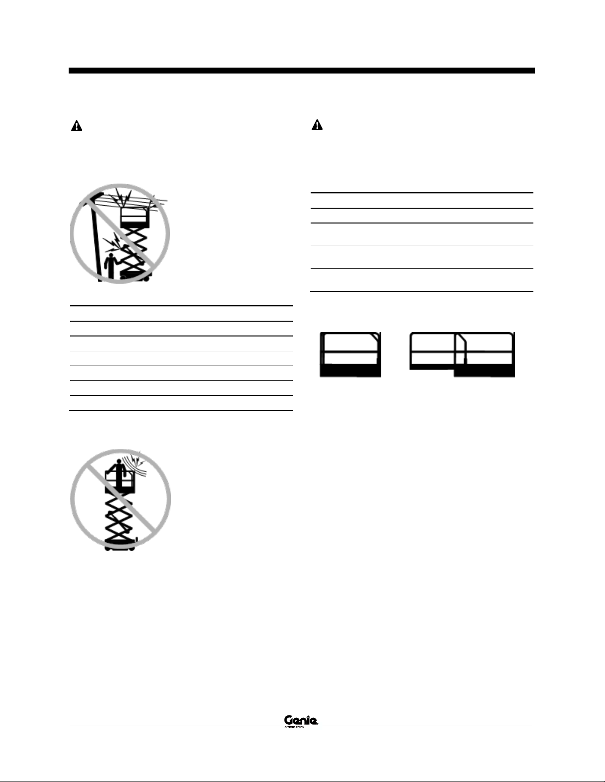
Tip-over Hazards
Occupants, equipment and materials shall not
exceed the maximum platform capacity or the
maximum platform capacity of the platform
extension.
Maximum capacity
Platform extended
Model
Platform
retracted
Platform
only
Extension
only
Maximum
occupants
GS-1432m
500 lbs
227 kg
250 lbs
113 kg
250 lbs
113 kg
Indoor – 2
Outdoor – 1
GS-1932m
500 lbs
227 kg
250 lbs
113 kg
250 lbs
113 kg
Indoor – 2
Outdoor – 1
Platform retracted
Platform extended
Extension only
Platform only
The weight of options and accessories, such as
panel carriers, will reduce the rated platform
capacity and must be subtracted from the platform
capacity. See the decals with the options and
accessories.
If using accessories, read, understand and obey
the decals, instructions and manuals with the
accessory.

Operator's Manual First Edition • First Printing
Work Area Safety
16 GS™-1432m • GS™-1932m Part No. 1307419GT
Do not raise the platform
unless the machine is on a
firm, level surface.
Do not depend on the tilt alarm as a level indicator.
The tilt alarm sounds on the chassis only when the
machine is on a severe slope.
If the tilt alarm sounds:
Lower the platform. Move the machine to a firm,
level surface. If the tilt alarm sounds when the
platform is raised, use extreme caution to lower
the platform.
Do not drive over 0.5 mph / 0.8 km/h with the
platform raised.
Follow ratings for allowable side force and number
of occupants shown below.
Do not raise the platform when wind speeds may
exceed 28 mph / 12.5 m/s. If wind speeds exceed
28 mph / 12.5 m/s when the platform is raised,
lower the platform and do not continue to operate
the machine.
Outdoor use: Do not operate the machine
outdoors with the indoor use button selected.
Do not operate the
machine in strong or gusty
winds. Do not increase the
surface area of the
platform or the load.
Increasing the area
exposed to the wind will
decrease machine
stability.
Use extreme care and
slow speeds while driving
the machine in the stowed
position across uneven
terrain, debris, unstable or
slippery surfaces and near
holes and drop-offs.
Do not drive the machine on or near uneven
terrain, unstable surfaces or other hazardous
conditions with the platform raised.
Do not use the machine as a crane.
Do not push the machine or other objects with the
platform.
Do not contact adjacent structures with the
platform.
Do not tie the platform to adjacent structures.
Do not place loads outside the platform perimeter.

First Edition • First Printing Operator's Manual
Work Area Safety
Part No. 1307419GT GS™-1432m • GS™-1932m 17
Do not operate the machine with the chassis trays
open.
Do not push off or pull
toward any object outside
of the platform.
Model
Maximum allowable
side force
Maximum
occupants
GS-1432m
Indoor – 90 lbs/400N
Outdoor – 45 lbs/200 N
Indoor – 2
Outdoor – 1
GS-1932m
Indoor – 90 lbs/400N
Outdoor – 45 lbs/200 N
Indoor – 2
Outdoor – 1
Do not alter or disable the limit switches.
Do not alter or disable machine components that
in any way affect safety and stability.
Do not replace items critical to machine stability
with items of different weight or specification.
Do not use batteries that weigh less than the
original equipment. Batteries are used as
counterweight and are critical to machine stability.
Each battery must weight a minimum of
61 lbs/28 kg. Charger tray including batteries must
weigh a minimum of 108lbs/49kg, G-CON tray
including batteries must weigh a minimum of
105lbs/48kg
Do not modify or alter a mobile elevated work
platform without prior written permission from the
manufacturer. Mounting attachments for holding
tools or other materials onto the platform,
toeboards, or guard rail system can increase the
weight in the platform and the surface area of the
platform or the load.
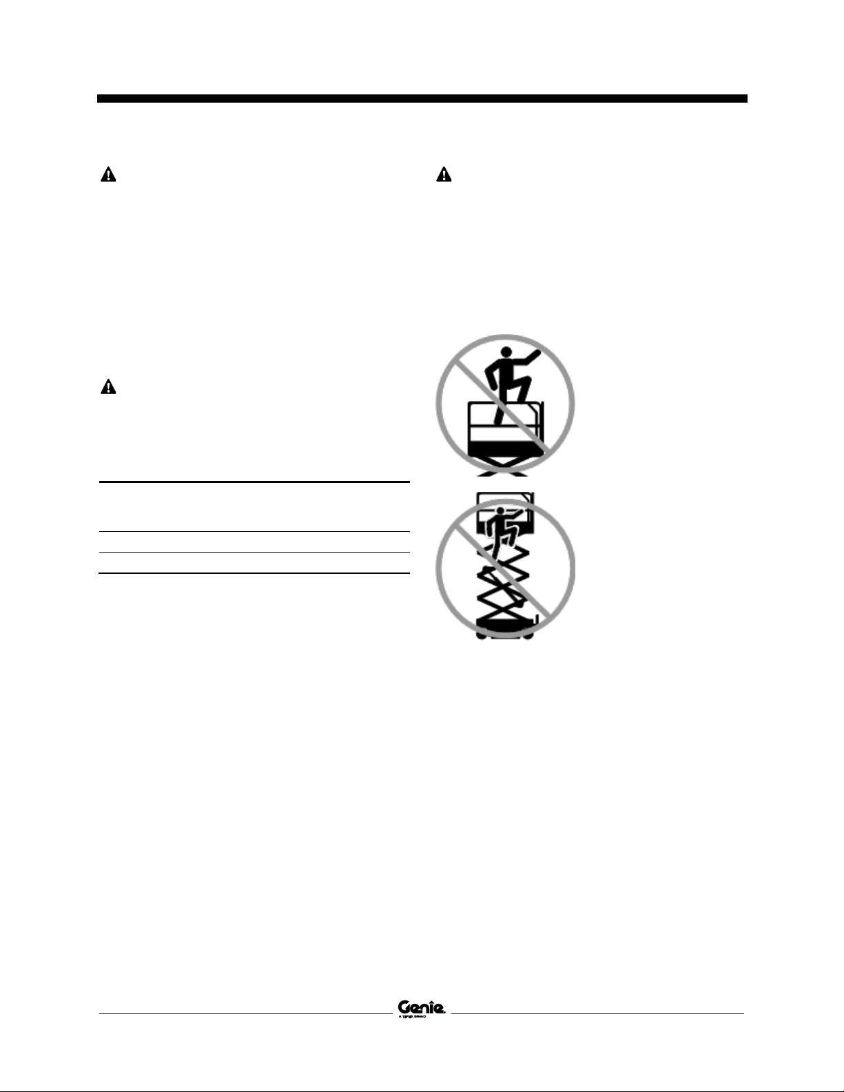
Do not place or attach
fixed or overhanging loads
to any part of this
machine.
Do not place ladders or
scaffolds in the platform or
against any part of this
machine.
Do not transport tools and materials unless they
are evenly distributed and can be safely handled
by person(s) in the platform.
Do not use the machine on a moving or mobile
surface or vehicle.
Be sure all tires are in good condition, castle nuts
are properly tightened and cotter pins are properly
installed.
Operator's Manual First Edition • First Printing
Work Area Safety
18 GS™-1432m • GS™-1932m Part No. 1307419GT
Crushing Hazard
Keep hands and limbs out of scissors.
Keep hands clear when folding rails.
Do not work under the platform or in the scissor
links without the safety arm in place.
Use common sense and planning when operating
the machine with the controller from the ground.
Maintain safe distances between the operator, the
machine and fixed objects.
Operation on Slopes Hazards
Do not drive the machine on a slope that exceeds
the slope and side slope rating of the machine.
Slope rating applies to machines in the stowed
position.
Model
Maximum slope
rating, stowed
position
Maximum side slope
rating, stowed
position
GS-1432m
25% (14°)
25% (14°)
GS-1932m
25% (14°)
25% (14°)
Note: Slope rating is subject to ground conditions
with one person in the platform and adequate
traction. Additional platform weight may reduce
slope rating. See Driving on a Slope in the
Operating Instructions section.
Fall Hazards
The guard rail system provides fall protection. If
occupant(s) of the platform are required to wear
personal fall protection equipment (PFPE) due to
job site or employer rules, PFPE and its use shall
be in accordance with the PFPE manufacturer’s
instructions and applicable governmental
requirements. Use approved lanyard attachment
point provided.
Do not sit, stand, or climb
on the platform guard
rails. Maintain a firm
footing on the platform
floor at all times.
Do not climb down from
the platform when raised.
Keep the platform floor clear of debris.
Close the entry gate before operating.
Do not operate the machine unless the guard rails
are properly installed and the entry is secured for
operation.
Do not enter or exit the platform unless the
machine is in the stowed position.
First Edition • First Printing Operator's Manual
Work Area Safety
Part No. 1307419GT GS™-1432m • GS™-1932m 19
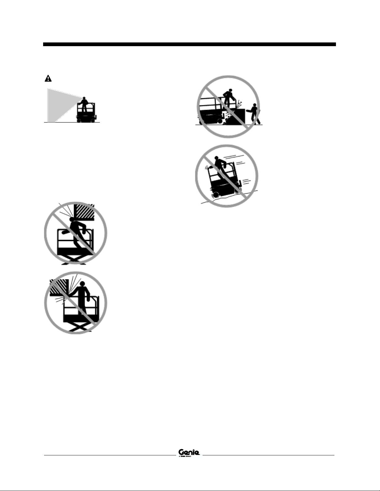
Collision Hazards
Be aware of limited sight
distance and blind spots
when driving or operating.
Be aware of extended platform position when
moving the machine.
The machine must be on a level surface and
wheels chocked or secured before releasing the
brakes.
Operators must comply with employer, job site,
and governmental rules regarding use of personal
protective equipment.
Check the work area for
overhead obstructions or
other possible hazards.
Be aware of crushing
hazards when grasping
the platform guard rail.
Observe and use color-coded direction arrows on
the platform controls and the platform decal plate
for drive and steer functions.
Do not lower the platform
unless the area below is
clear of personnel and
obstructions.
Limit travel speed
according to the condition
of the ground surface,
congestion, slope,
location of personnel, and
any other factors which
may cause collision.
Do not operate a machine in the path of any crane
or moving overhead machinery unless the controls
of the crane have been locked out and/or
precautions have been taken to prevent any
potential collision.
No stunt driving or horseplay while operating a
machine.

Operator's Manual First Edition • First Printing
Work Area Safety
20 GS™-1432m • GS™-1932m Part No. 1307419GT
Bodily Injury Hazard
Do not operate the machine with a hydraulic oil or
air leak. An air leak or hydraulic leak can penetrate
and/or burn skin.
Improper contact with components under any
cover will cause serious injury. Only trained
maintenance personnel should access
compartments. Access by the operator is only
advised when performing a pre-operation
inspection. All compartments must remain closed
and secured during operation.
Explosion and Fire Hazards
Do not operate the machine or charge the battery
in hazardous locations or locations where
potentially flammable or explosive gases or
particles may be present.
Damaged Machine Hazards
Do not use a damaged or malfunctioning machine.
Conduct a thorough pre-operation inspection of
the machine and test all functions before each
work shift. Immediately tag and remove from
service a damaged or malfunctioning machine.
Be sure all maintenance has been performed as
specified in this manual and the appropriate Genie
service manual.
Be sure all decals are in place and legible.
Be sure the operator's, safety, and responsibilities
manuals are complete, legible, and in the storage
container located on the machine.
Component Damage Hazards
Do not use any battery charger greater than 24V
to charge the batteries.
Do not use the machine as a ground for welding.
First Edition • First Printing Operator's Manual
Work Area Safety
Part No. 1307419GT GS™-1432m • GS™-1932m 21
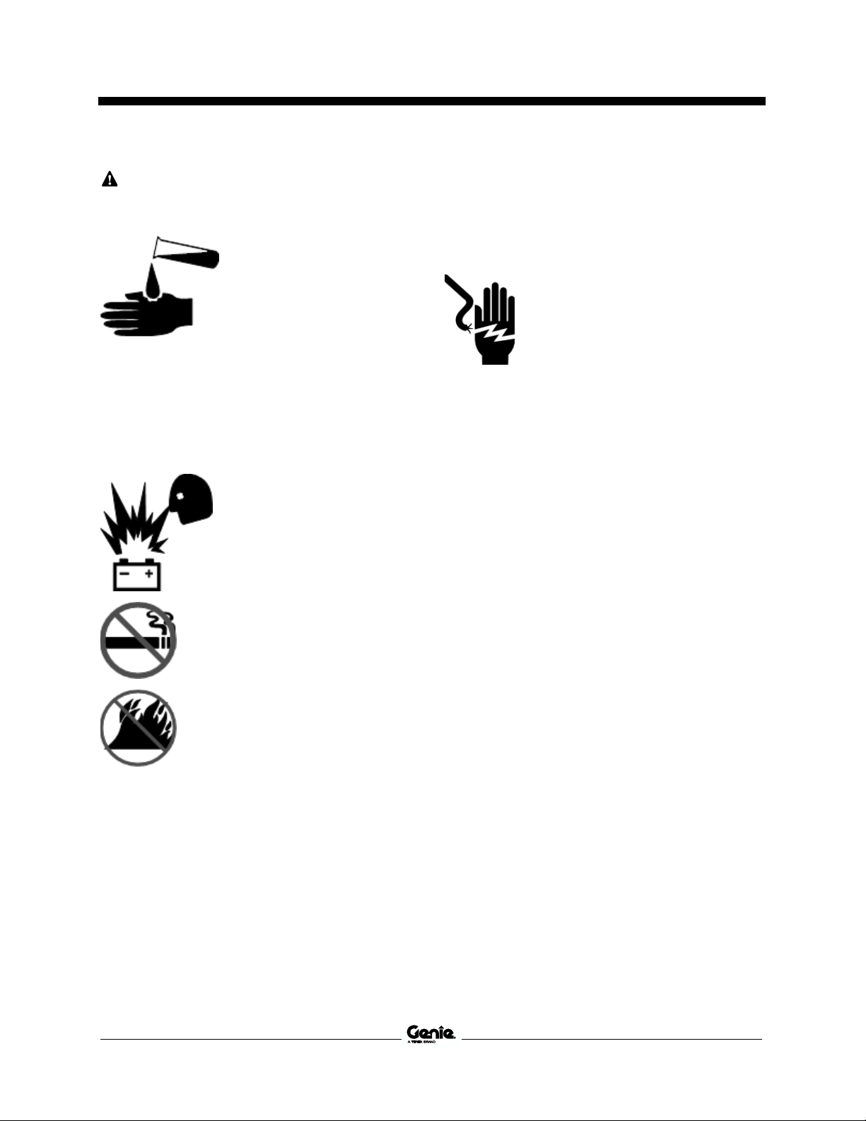
Battery Safety
Burn Hazards
Batteries contain acid.
Always wear protective
clothing and eye wear when
working with batteries.
Avoid spilling or contacting
battery acid. Neutralize
battery acid spills with baking
soda and water.
Do not expose the batteries or the charger to
water or rain during charging.
Explosion Hazards
Keep sparks, flames, and
lighted tobacco away from
batteries. Batteries emit
explosive gas.
The battery tray may remain
open during the entire
charging cycle.
Do not contact the battery
terminals or the cable
clamps with tools that may
cause sparks.
Component Damage Hazard
Do not use any battery charger greater than 24V
to charge the batteries.
Electrocution/Burn Hazards
Connect the battery charger to a
grounded, AC 3-wire electrical
outlet only.
Inspect daily for damaged cords,
cables and wires. Replace
damaged items before operating.
Avoid electrical shock from contact with battery
terminals. Remove all rings, watches and other
jewelry.
Tip-over Hazard
Do not use batteries that weigh less than the
original equipment. Batteries are used as
counterweight and are critical to machine stability.
Each battery must weight a minimum of
61 lbs/28 kg. Charger tray including batteries must
weigh a minimum of 108lbs/49kg, G-CON tray
including batteries must weigh a minimum of
105lbs/48kg
Lifting Hazard
Use the appropriate number of people and proper
lifting techniques when lifting batteries.

Operator's Manual First Edition • First Printing
Work Area Safety
22 GS™-1432m • GS™-1932m Part No. 1307419GT
Lockout After Each Use
1 Select a safe parking location—firm level
surface, clear of obstruction and traffic.
2 Lower the platform.
3 Turn the key switch to the off position and
remove the key to secure from unauthorized
use.
4 Charge the batteries.

First Edition • First Printing Operator's Manual
Legend
Part No. 1307419GT GS™-1432m • GS™-1932m 23
Legend
1 Platform entry gate
2 Platform guard rails
3 Lanyard anchorage points
4 Platform controls
5 Platform extension
6 Manual storage container
7 Foot switch (if equipped)
8 GFCI outlet
9 Platform extension release pedal
10 Air line to platform (optional)
11 Inverter (optional)
12 Safety arm
13 Steer tire
14 Tilt alarm
15 Ground controls
16 LCD readout
17 Pothole guard
18 Flashing beacon
19 Brake release switch (hydraulic side) (e-drive
option)
20 Transport tie-down
21 Forklift pocket
22 Entry ladder / transport tie-down
23 Non-steer tire
24 Auxiliary lowering knob
25 Battery charger (on battery side of machine)

Operator's Manual First Edition • First Printing
Controls
24 GS™-1432m • GS™-1932m Part No. 1307419GT
Controls
The ground control station is to be used as a means to raise the platform for function tests and for storage
purposes. The ground control station can be used in the event of an emergency to rescue an
incapacitated person in the platform.
Ground Control Panel
1 Tech Pro Link Connector
2 Key switch for platform/off/ground selection
Turn the key switch to the platform position and
the platform controls will operate. Turn the key
switch to the off position and the machine will be
off. Turn the key switch to the ground position
and the ground controls will operate.
3 7A breaker for electrical circuits
4 Red Emergency Stop button
Push in the red Emergency Stop button to the off
position to stop all functions. Pull out the red
Emergency Stop button to the on position to
operate the machine.
5 LCD diagnostic readout
6 Menu enter button
7 Menu down button
8 Platform down button
9 Platform up button
10 Lift function enable button
Press and hold this button to activate the lift
function.
11 Menu up button
12 Menu escape button
First Edition • First Printing Operator's Manual
Controls
Part No. 1307419GT GS™-1432m • GS™-1932m 25
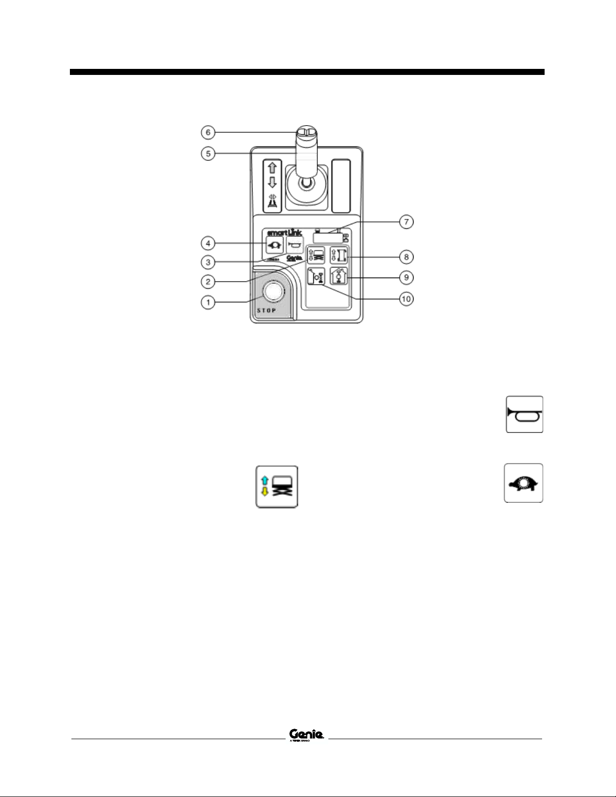
Platform Control Panel
1 Red Emergency Stop button
Push in the red Emergency Stop button to the
off position to stop all functions. Pull out the
red Emergency Stop button to the on position
to operate the machine.
2 Lift function button
Push this button to activate the lift
function.
3 Horn button
Press the horn button and the horn
will sound. Release the horn
button and the horn will not sound.
4 Drive speed select button
Press this button to activate the
slow drive function. The indicator
light will be on when slow drive is
selected.

Operator's Manual First Edition • First Printing
Controls
26 GS™-1432m • GS™-1932m Part No. 1307419GT
5 Proportional control handle and function
enable switch for drive, steer, and lift functions
Lift function: Press and hold the function
enable switch to enable the lift function on the
platform control handle. Move the control
handle in the direction indicated by the blue
arrow and the platform will raise. Move the
control handle in the direction indicated by the
yellow arrow and the platform will lower. The
descent alarm should sound while the platform
is lowering.
Drive function: Press and hold the function
enable switch to enable the drive function on
the platform control handle. Move the control
handle in the direction indicated by the blue
arrow on the control panel and the machine
will move in the direction that the blue arrow
points. Move the control handle in the direction
indicated by the yellow arrow on the control
panel and the machine will move in the
direction that the yellow arrow points.
6 Thumb rocker switch for steer function
Press the left side of the thumb
rocker and the machine will turn in
the direction the blue triangle
points on the platform control
panel.
Press the right side of the thumb
rocker and the machine will turn in
the direction the yellow triangle
points on the platform control
panel.
7 LED diagnostic readout, battery charge
indicator and lift/drive mode indicator
8 Drive function button
Push this button to activate the
drive function.
9 Indoor use button
Press this button for indoor use
Note: Selecting indoor use permits
elevating to maximum indoor
platform height. Refer to
specification pages.
10 Outdoor use button
Press this button for outdoor use
Note: Selecting outdoor use
permits elevating to maximum
outdoor platform height. Refer to
specification pages.

First Edition • First Printing Operator's Manual
Inspections
Part No. 1307419GT GS™-1432m • GS™-1932m 27
Inspections
Do Not Operate Unless:
You learn and practice the principles of safe
machine operation contained in this operator’s
manual.
1 Avoid hazardous situations.
2 Always perform a pre-operation
inspection.
Know and understand the pre-operation
inspection before going on to the next
section.
3 Always perform function tests prior to use.
4 Inspect the workplace.
5 Only use the machine as it was intended.
Pre-operation Inspection
Fundamentals
It is the responsibility of the operator to perform a
pre-operation inspection and routine maintenance.
The pre-operation inspection is a visual inspection
performed by the operator prior to each work shift.
The inspection is designed to discover if anything
is apparently wrong with a machine before the
operator performs the function tests.
The pre-operation inspection also serves to
determine if routine maintenance procedures are
required. Only routine maintenance items specified
in this manual may be performed by the operator.
Refer to the list on the next page and check each
of the items.
If damage or any unauthorized variation from
factory delivered condition is discovered, the
machine must be tagged and removed from
service.
Repairs to the machine may only be made by a
qualified service technician, according to the
manufacturer’s specifications. After repairs are
completed, the operator must perform a preoperation inspection again before going on to the
function tests.
Scheduled maintenance inspections shall be
performed by qualified service technicians,
according to the manufacturer’s specifications and
the requirements listed in the responsibilities
manual.

Operator's Manual First Edition • First Printing
Inspections
28 GS™-1432m • GS™-1932m Part No. 1307419GT
Pre-operation Inspection
Be sure that the operator’s, safety, and
responsibilities manuals are complete, legible
and in the storage container located in the
platform.
Be sure that all decals are legible and in place.
See Inspections section.
Check for hydraulic oil leaks and proper oil
level. Add oil if needed. See Maintenance
section.
Check for battery fluid leaks and proper fluid
level. Add distilled water if needed. See
Maintenance section.
Check the following components or areas for
damage, improperly installed, or missing parts and
unauthorized modifications:
Electrical components, wiring, and
electrical cables
Hydraulic hoses, fittings, cylinders, and
manifolds
Drive motors
Wear pads
Tires and wheels
Limit switches, alarms and horn
Alarms and beacons (if equipped)
Nuts, bolts and other fasteners
Brake release components
Safety arm
Platform extension
Scissor pins and retaining fasteners
Platform control joystick
Battery pack and connections
Ground strap
Platform entry gate
Pothole guards
Lanyard anchorage points
Platform overload components
Check entire machine for:
Cracks in welds or structural components
Dents or damage to machine
Excessive rust, corrosion or oxidation
Verify that all structural and other critical
components are present and all associated
fasteners and pins are in place and properly
tightened.
Be sure side rails are installed and bolts are
fastened.
Be sure that the chassis trays are closed and
latched and the batteries are properly
connected.
Note: If the platform must be raised to inspect the
machine, make sure the safety arm is in place.
See Operating Instructions section.

First Edition • First Printing Operator's Manual
Inspections
Part No. 1307419GT GS™-1432m • GS™-1932m 29
Do Not Operate Unless:
You learn and practice the principles of safe
machine operation contained in this operator’s
manual.
1 Avoid hazardous situations.
2 Always perform a pre-operation inspection.
3 Always perform function tests prior to
use.
Know and understand the function tests
before going on to the next section.
4 Inspect the workplace.
5 Only use the machine as it was intended.
Function Test Fundamentals
The function tests are designed to discover any
malfunctions before the machine is put into
service. The operator must follow the step-by-step
instructions to test all machine functions.
A malfunctioning machine must never be used. If
malfunctions are discovered, the machine must be
tagged and removed from service. Repairs to the
machine may only be made by a qualified service
technician, according to the manufacturer’s
specifications.
After repairs are completed, the operator must
perform a pre-operation inspection and function
tests again before putting the machine into
service.
Operator's Manual First Edition • First Printing
Inspections
30 GS™-1432m • GS™-1932m Part No. 1307419GT
At the Ground Controls
1 Select a test area that is firm, level and free of
hazards.
2 Be sure the batteries are connected.
3 Pull out the platform and ground red
Emergency Stop button to the on position.
4 Turn the key switch to ground control.
5 Observe the diagnostic LED readout on the
platform controls.
Result: The LED should look like the picture
below.
6 Observe the diagnostic LCD readout on the
ground controls.
Result: The LCD should look like the picture
below.
Test Emergency Stop
7 Push in the ground red Emergency Stop
button to the off position.
Result: No functions should operate.
8 Pull out the red Emergency Stop button to the
on position.
Test the Up/Down Functions
The audible warnings on this machine and the
standard horn all come from the same central
alarm. The horn is a constant tone. The descent
alarm sounds at 60 beeps per minute. The alarm
sounds at 180 beeps per minute when the pothole
guards have not deployed and when the machine
is not level. An optional automotive-style horn is
also available.
9 Do not press the lift function enable button.
10 Press the platform up or platform down button.
Result: The lift function should not operate.
11 Do not press the platform up or platform down
buttons.
12 Press the lift function enable button.
Result: The lift function should not operate.
13 Press and hold the lift function enable button,
and press the platform up button.
Result: The outdoor area of operation should
be selected and the platform should raise.
14 Press and hold the lift function enable button,
and press the platform down button.
Result: The platform should lower. The
descent alarm should sound while the platform
is lowering.

First Edition • First Printing Operator's Manual
Inspections
Part No. 1307419GT GS™-1432m • GS™-1932m 31
Test Auxiliary Lowering
15 Activate the up function by pressing the lift
enable button and platform up button, and
raise the platform approximately 2 ft. / 60 cm.
16 Pull the auxiliary lowering knob, located at the
rear of the bottom link.
Result: The platform should lower. The
descent alarm will not sound.
Test the Tilt Sensor Operation
17 Press the ground control down button
(button 3)
Result: The ground control LCD screen will
display the status of the tilt sensor.
18 Turn the key switch to platform control.
At the Platform Controls
Test Emergency Stop
19 Push in the platform red Emergency Stop
button to the off position.
Result: No functions should operate.
Test the Alarm for Tilt Sensor
20 Pull out the red Emergency Stop button to the
on position.
21 Press the horn button.
Result: The platform alarm, chassis alarm, and
automotive horn (if equipped) should sound.
Test the Function Enable Switch and the
Up/Down Functions
22 Do not hold the function enable switch on the
control handle.
23 Slowly move the control handle in the direction
indicated by the blue arrow, then in the
direction indicated by the yellow arrow.
Result: No functions should operate.
24 Press the lift function button.
25 Wait seven seconds for the lift function to time
out.
26 Slowly move the control handle in the direction
indicated by the blue arrow, then in the
direction indicated by the yellow arrow.
Result: The lift function should not operate.

Operator's Manual First Edition • First Printing
Inspections
32 GS™-1432m • GS™-1932m Part No. 1307419GT
27 Press the lift function button.
28 Press and hold the function enable switch on
the control handle. Slowly move the control
handle in the direction indicated by the blue
arrow.
Machines equipped with foot switch: Press and
hold the foot switch and press and hold the
function enable switch on the control handle at the
same time.
Result: The platform should raise. The pothole
guards should deploy. The outdoor use button
should illuminate.
29 Release the control handle.
Result: The platform should stop raising.
30 Press and hold the function enable switch on
the control handle. Slowly move the control
handle in the direction indicated by the yellow
arrow.
Result: The platform should lower. The
descent alarm should sound while the platform
is lowering.
Test the Outdoor Use Button
31 Do not press and hold the function enable
switch on control handle.
32 Press the outdoor use button.
Result: The LED under the outdoor button will
illuminate.
33 Press the lift function enable button.
34 Press and hold the function enable switch on
the control handle. Slowly move the control
handle in the direction indicated by the blue
arrow.
GS-1432m: Result: The platform should raise
to a maximum of 14 ft 1 in/4.3 m and stop. The
alarm should sound. The platform controls
LED readout should display OHL.
GS-1932m: Result: The platform should raise
to a maximum of 17 ft 0 in/5.2 m and stop. The
alarm should sound. The platform controls
LED readout should display OHL.
Test the Drive Function Button
35 Press the drive function button.
36 Wait seven seconds for the drive function to
time out.Slowly move the control handle in the
direction indicated by the blue arrow, then in
the direction indicated by the yellow arrow.
Result: No functions should operate.

First Edition • First Printing Operator's Manual
Inspections
Part No. 1307419GT GS™-1432m • GS™-1932m 33
Test the Steering
Note: When performing the steer and drive
function tests, stand in the platform facing the
steer end of the machine.
37 Press the drive function button.
38 Press and hold the function enable switch on
the control handle.
39 Press the thumb rocker switch on top of the
control handle in the direction indicated by the
blue triangle on the control panel.
Result: The steer wheels should turn in the
direction indicated by the blue triangle.
40 Press the thumb rocker switch on top of the
control handle in the direction indicated by the
yellow triangle, on the control panel.
Result: The steer wheels should turn in the
direction indicated by the yellow triangle.
Test Drive and Braking
41 Press the drive function button.
42 Press and hold the function enable switch on
the control handle.
Machines equipped with foot switch: Press and
hold the foot switch and press and hold the
function enable switch on the control handle at the
same time.
43 Slowly move the control handle in the direction
indicated by the blue arrow on the control
panel until the machine begins to move, then
return the control handle to the center position.
Result: The machine should move in the
direction that the blue arrow points on the
control panel, then come to an abrupt stop
when the control handle is returned to the
center position.
44 Slowly move the control handle in the direction
indicated by the yellow arrow on the control
panel until the machine begins to move, then
return the control handle to the center position.
Result: The machine should move in the
direction that the yellow arrow points on the
control panel, then come to an abrupt stop
when the control handle is returned to the
center position.
Note: The brakes must be able to hold the
machine on any slope it is able to climb.

Operator's Manual First Edition • First Printing
Inspections
34 GS™-1432m • GS™-1932m Part No. 1307419GT
Test Drive Tilt Cutout
Note: Perform this test from the ground with the
platform controller. Do not stand in the platform.
45 Fully lower the platform.
46 Drive the machine onto a slope where the
chassis angle is greater than 1.5° side to side.
47 Raise the platform to approximately
9 ft/2.74 m.
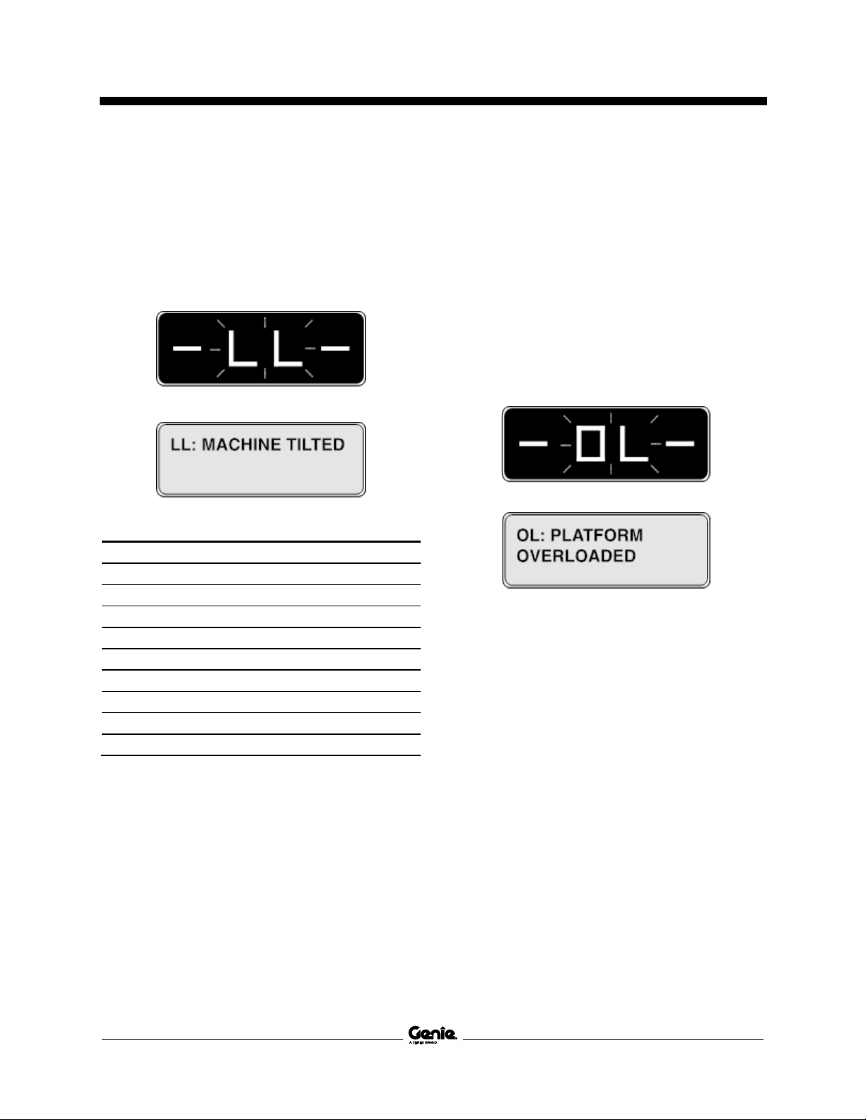
Result: The platform should stop and the tilt
alarm will sound at 180 beeps per minute. The
platform controls LED readout should display
LL and the ground controls LCD should
display LL: Machine Tilted.
48 Press the drive function button.
49 Press and hold the function enable switch on
the control handle.
50 Move the control handle in the direction
indicated by the blue arrow, then move the
control handle in the direction indicated by the
yellow arrow.
Result: The drive function should not work in
either direction.
51 Fully lower the platform.
52 Drive the machine.
Result: The machine should drive.
53 Return to level ground and raise the platform
in excess of approximately 9 ft/2.74 m.
54 Drive the machine onto a slope where the
pitch angle is greater than 1.5° side to side.
Result: The machine should stop once the
machine reaches 1.5° of chassis tilt and the tilt
alarm will sound at 180 beeps per minute. The
platform controls LED readout should display
LL and the ground controls LCD should
display LL: Machine Tilted
55 Return to level ground and fully lower the
platform.
56 Drive the machine onto a slope where the
chassis angle is greater than 3° front to back.
57 Raise the platform to approximately
9 ft/2.74 m.
Result: The platform should stop and the tilt
alarm will sound at 180 beeps per minute. The
platform controls LED readout should display
LL and the ground controls LCD should
display LL: Machine Tilted.
58 Press the drive function button.
59 Press and hold the drive/steer function enable
switch on the control handle.
60 Move the control handle in the direction
indicated by the blue arrow, then move the
control handle in the direction indicated by the
yellow arrow.
Result: The drive function should not work in
either direction.

First Edition • First Printing Operator's Manual
Inspections
Part No. 1307419GT GS™-1432m • GS™-1932m 35
61 Fully lower the platform.
62 Drive the machine.
Result: The machine should drive.
63 Return to level ground and raise the platform
in excess of approximately 9 ft/2.74 m.
64 Drive the machine onto a slope where the
pitch angle is greater than 3° front to back.
Result: The machine should stop once the
machine reaches 3° of chassis tilt and the tilt
alarm will sound at 180 beeps per minute. The
platform controls LED readout should display
LL and the ground controls LCD should
display LL: Machine Tilted
65 Fully lower the platform and return to level
ground.
Test Elevated Drive Speed
66 Raise the platform approximately 9.1 ft/2.78 m
from the ground.
67 Press the drive function button.
68 Press and hold the function enable switch on
the control handle.Slowly move the control
handle to full drive position.
Result: The maximum achievable drive speed
with the platform raised should not exceed
0.72 ft / 22 cm per second.
If the drive speed with the platform raised exceeds
0.72 ft / 22 cm per second, immediately tag and
remove the machine from service.
Test the Pothole Guards
Note: The pothole guards should automatically
deploy when the platform is raised. The pothole
guards activate limit switches that allow the
machine to continue to function. If the pothole
guards do not deploy, an alarm sounds and the
machine will not drive or steer.
69 Raise the platform.
Result: When the platform is raised 4 ft / 1.2 m
from the ground, the pothole guards should
deploy.
70 Press on the pothole guards on one side, and
then the other.
Result: The pothole guards should not move.
71 Lower the platform.
Result: The pothole guards should return to
the stowed position.
72 Place a 2x4 or similar piece of wood under a
pothole guard.
73 Raise the platform.
Result: Before the platform is raised 7 ft /
2.1 m from the ground, an alarm should
sound. The platform controls LED readout
should display PHS and the ground controls
LCD should display PHS: Pothole Guard
Stuck.
74 Press the drive function button.

Operator's Manual First Edition • First Printing
Inspections
36 GS™-1432m • GS™-1932m Part No. 1307419GT
75 Press and hold the function enable switch on
the control handle.
76 Slowly move the control handle in the direction
indicated by the blue arrow, then in the
direction indicated by the yellow arrow.
Result: The machine should not move forward
or backward.
77 Press the drive function button.
78 Press and hold the function enable switch on
the control handle.
79 Press the thumb rocker switch on top of the
control handle in the direction indicated by the
blue and yellow triangles on the control panel.
Result: The steer wheels should not turn left or
right.
80 Fully lower the platform.
81 Remove the 2x4 or similar piece of wood.

First Edition • First Printing Operator's Manual
Inspections
Part No. 1307419GT GS™-1432m • GS™-1932m 37
Do Not Operate Unless:
You learn and practice the principles of safe
machine operation contained in this operator’s
manual.
1 Avoid hazardous situations.
2 Always perform a pre-operation inspection.
3 Always perform function tests prior to use.
4 Inspect the workplace.
Know and understand the workplace
inspection before going on to the next
section.
5 Only use the machine as it was intended.
Workplace Inspection
Fundamentals
The workplace inspection helps the operator
determine if the workplace is suitable for safe
machine operation. It should be performed by the
operator prior to moving the machine to the
workplace.
It is the operator’s responsibility to read and
remember the workplace hazards, then watch for
and avoid them while moving, setting up, and
operating the machine.
Workplace Inspection Checklist
Be aware of and avoid the following hazardous
situations:
drop-offs or holes
bumps, floor obstructions, or debris
sloped surfaces
unstable or slippery surfaces
overhead obstructions and high voltage
conductors
hazardous locations
inadequate surface support to withstand all
load forces imposed by the machine
wind and weather conditions
the presence of unauthorized personnel
other possible unsafe conditions

Operator's Manual First Edition • First Printing
Inspections
38 GS™-1432m • GS™-1932m Part No. 1307419GT
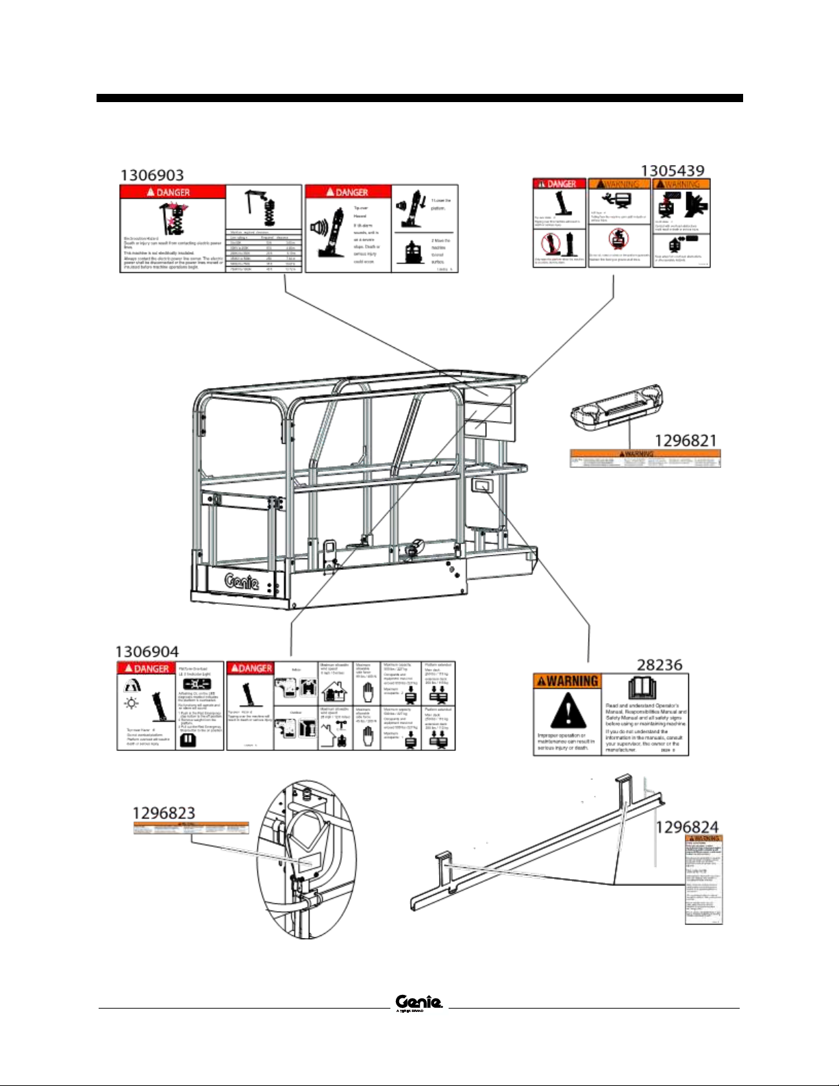
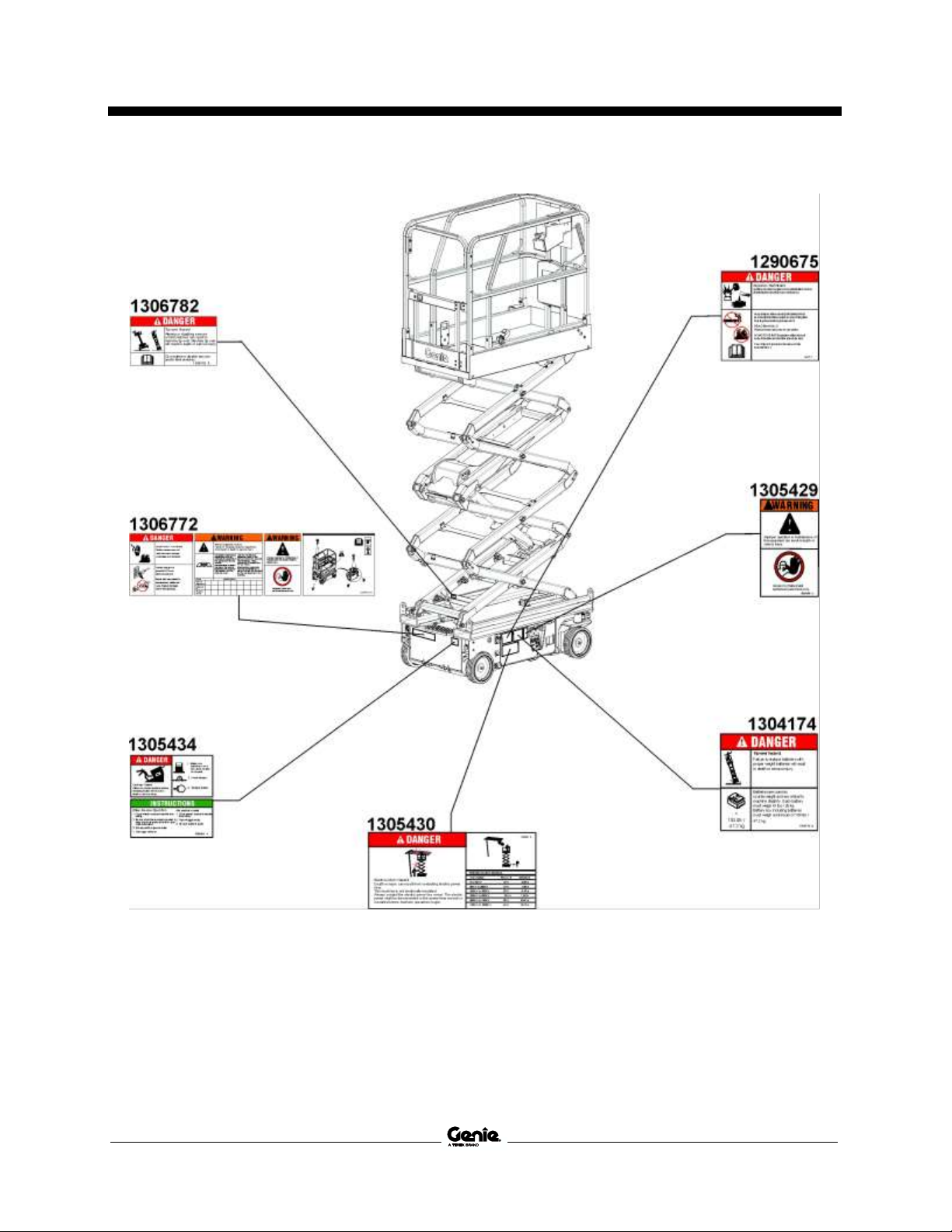
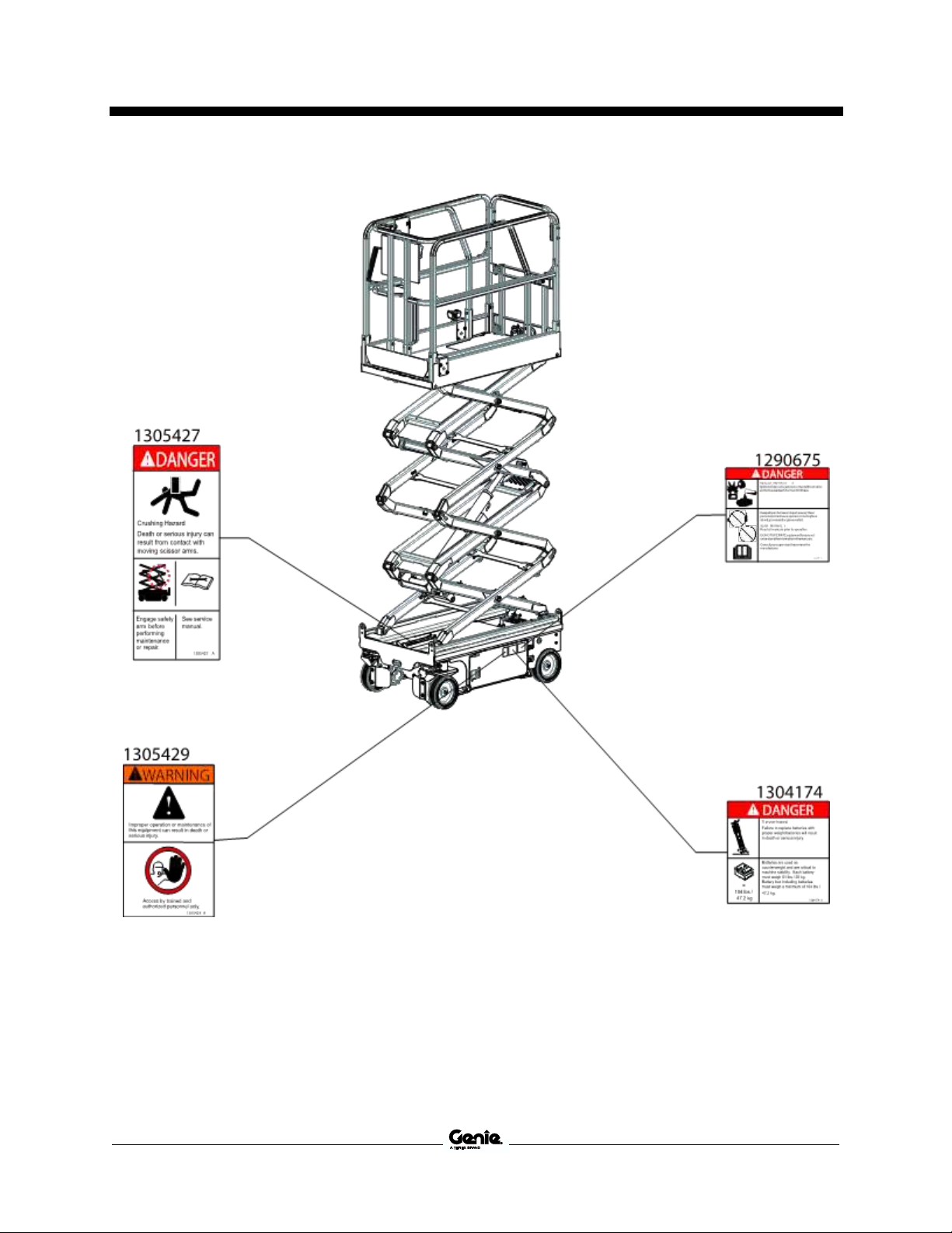
Inspection for Decals with Words
Determine whether the decals on your machine
have words or symbols. Use the appropriate
inspection to verify that all decals are legible and
in place.
Part No. Decal Description
Qty
28236 Warning – Improper Operation
1
38149 Label – Patents
1
43618 Label – Directional Arrows
1
72086 Label – Lifting Point
4
72143 Label – Emergency Stop
1
82557 Label – Platform Controls Location
1
128518 Label – Warning Ribbon
139 in
137605 Label – Emergency Stop, Platform
Control
1
137656 Label – Drive/Steer Direction,
Platform Control
1
1272242 Label – Machine Registration/Owner
Transfer
1
1281174 Label – Lanyard Anchorage Point, Fall
Arrest/Fall Restrained*
5
1283810 Label – Platform Control Panel
1
1283878 Label – Tech Pro Link
1
1280819 Label – Warning, Prop 65
1
1290675 Danger – Explosion/Burn Hazard
2
1292990 Label – Release Brake
1
1293324 Label – ICES-2/CAN-2 Compliance
1
1294398 Label – ANSI/CSA Compliant
1
1294682 Label – Ground Control Panel,
GS-1330m
1
1296034 Label – Smartlink Dual Zone
2
1296821 Decal – Warning, Tool Box
1
1296823 Decal – Warning, Pipe Cradle
2
1296824 Decal – Warning, Panel Carrier
2
1301158 Label – Fault Codes
1
1304174 Decal – Danger-Tip-Over, Battery,
GS-1932m
2
1304175 Decal – Instruct, Battery Connect,
GS-1932m
1
1304176 Decal – Label, Tire Specs, GS-1932m
4
1304177 Label – Wheel Load GS-1932m*
4
1304178 Decal – Electric Drive, E-drive
2
Part No. Decal Description
Qty
1304179 Label – Transport Diagram,
GS-1932m*
1
1304183 Decal – Cosmetic Genie, GS-1932m
2
1305410 Label – Transport Tie Down*
3
1305415 Label – Charge Status Ind.*
1
1305416 Label – Power to Platform, 115V*
2
1305417 Label – Power to Platform, 230V*
2
1305418 Label – Power to Charger, 115UK,*
1
1305419 Label – Power to Charger, 230V EU*
1
1305420 Label – Airline 110 PSI*
2
1305424 Label – Direction Arrows*
1
1305427 Label – Danger, Use Safety Arm*
1
1305428 Label – Instructions, Charger Op.*
1
1305429 Label – Improper Operation,Mini*
2
1305430 Label – Danger, Elec. Hazard,
GS, Mini*
1
1305431 Label – Operation Inst.,GCON*
1
1305434 Label – Danger, Brake Release
Safety*
1
1305435 Label – Emergency Lowering*
1
1305436 Label – Chevron Rando*
1
1305439 Label – Danger/Warning Combo*
1
1305489 Decal – Cosmetic Genie, GS-1432m
2
1306772 Label – Combo, Elec. Haz., Annual
Insp., Comp Access, Transport Inst.
1
1306781 Label – Hydraulic Tray Open Diagram
1
1306782 Label – Danger Do Not Alter Switch,
Mini
1
1306903 Label – Combo, Tip-over Haz., Plat.
Overload, Max Cap, Max Side Force
1
1306904 Label – Combo, Elec. Haz., Tip-over
Haz Tilt Alarm*
1
1307060 Label – Safety Arm, Mini
1
1307117 Label – Wheel Load GS-1432m*
4
1309406 Decal – Black, Cosmetic Genie,
GS-1932m
2
1309408 Decal – Black, Cosmetic Genie,
GS-1432m
2
Shading indicates decal is hidden from view, i.e.
under covers
* These decals are model, option or configuration
specific.

First Edition • First Printing Operator's Manual
Inspections
Part No. 1307419GT GS™-1432m • GS™-1932m 39

Operator's Manual First Edition • First Printing
Inspections
40 GS™-1432m • GS™-1932m Part No. 1307419GT
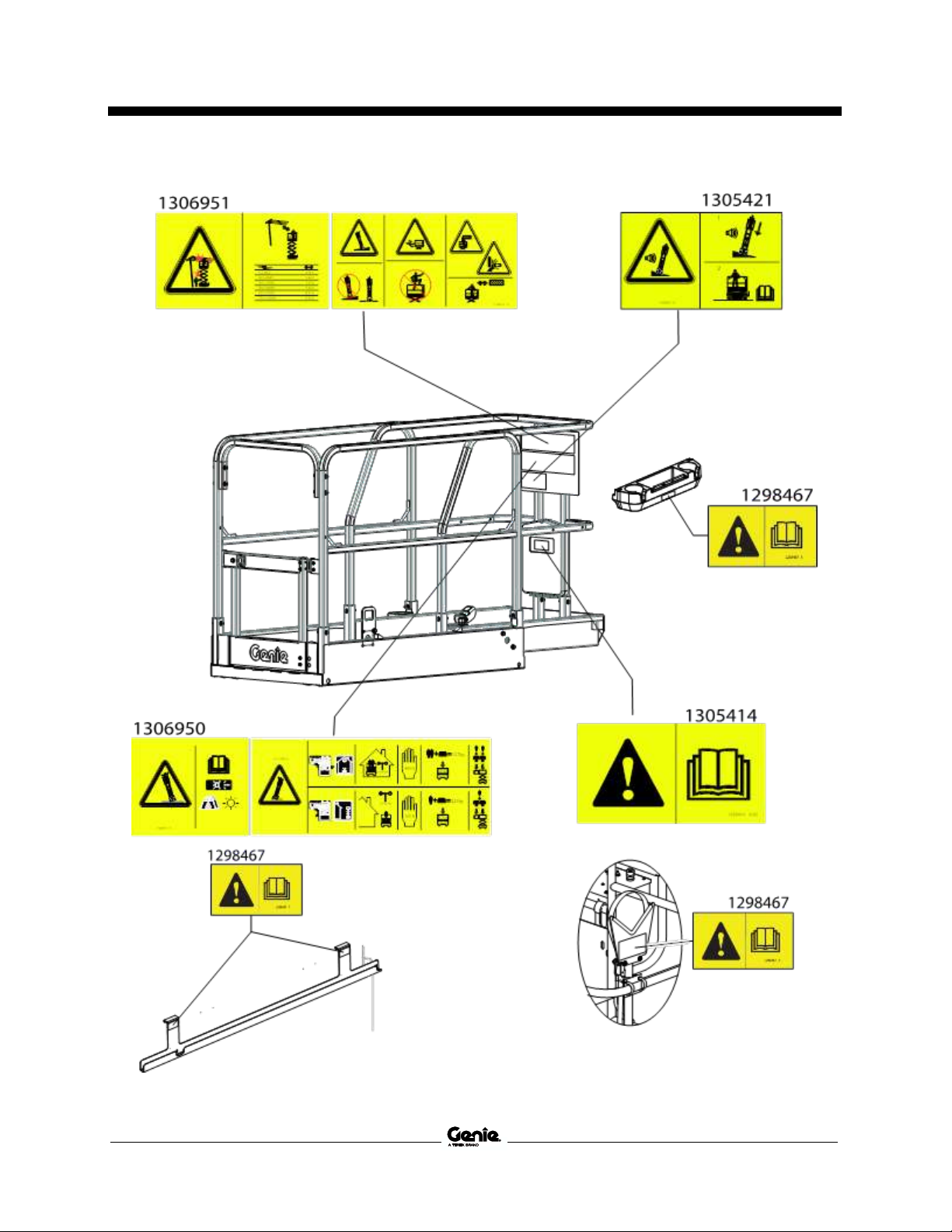
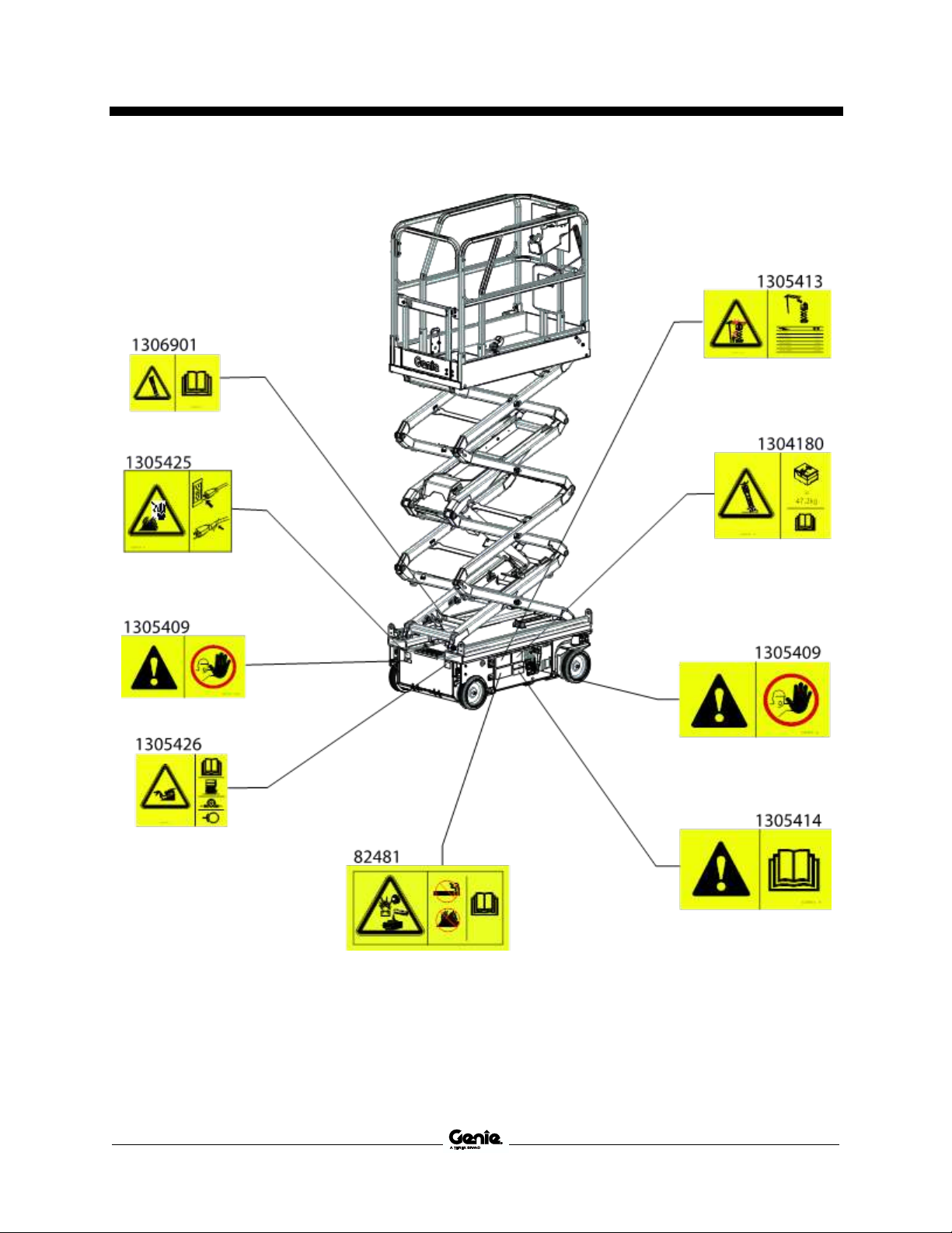
Inspection for Decals with
Symbols
Determine whether the decals on your machine
have words or symbols. Use the appropriate
inspection to verify that all decals are legible and
in place.
Part No. Decal Description
Qty
38149 Label – Patents
1
43618 Label – Directional Arrows
1
72086 Label – Lifting Point
4
72143 Label – Emergency Stop
1
82481 Label – Battery/Charger Safety
2
128518 Label – Warning Ribbon
139 in
137605 Label – Emergency Stop, Platform
Control
1
137656 Label – Drive/Steer Direction,
Platform Control
1
1272242 Label – Machine Registration
1
1281174 Label – Lanyard Anchorage Point,
Fall Arrest/Fall Restrained
5
1283810 Label – Platform Control Panel
1
1283878 Label – Tech Pro Link
1
1292052 Label – Emergency Lowering
GS-1330m
1
1292990 Label – Release Brake
1
1294682 Label – Ground Control Panel,
GS-1330m
1
1296034 Label – Smartlink Dual Zone
2
1298467 Label – Read the Manual
5
1304177 Label – Wheel Load GS-1932m*
4
1304178 Decal – Electric Drive, E-drive
2
1304179 Label – Transport Diagram,
GS-1932m*
2
1304180 Label – Tip-over Hazard, Batteries,
GS-1932m*
2
1304183 Decal – Cosmetic Genie, GS-1932m
2
Part No. Decal Description
Qty
1305409 Label – Compartment Access,
Symbol
3
1305410 Label – Transport Tie Down
3
1305411 Label – Hazard, Safety Arm, Symbol
1
1305412 Label – Safety Arm, Symbol
1
1305413 Label – Danger, Electrocution Hazard
1
1305414 Label – Read the Manual
2
1305415 Label – Charge Status Ind.
1
1305416 Label – Power to Platform, 115V*
2
1305417 Label – Power to Platform, 230V*
2
1305418 Label – Power to Charger, 115UK,*
1
1305419 Label – Power to Charger, 230V EU*
1
1305420 Label – Airline 110 PSI*
2
1305421 Label – Tip-over Hazard, Tilt Alarm
1
1305424 Label – Direction Arrows*
2
1305425 Label – Electrocution Hazard, Plug
1
1305426 Label – Brake Release Safety and
Operating Instructions
1
1305437 Label – Power to Platform, Aktio*
2
1305496 Label – Power to Charger, Aktio*
1
1305489 Decal – Cosmetic Genie, GS-1432m
2
1306781 Label – Hydraulic Tray Open
Diagram
1
1306901 Label – Tip-over Hazard, Limit Switch
1
1306950 Label – Plat. Overload, Max Cap.,
Side Force
1
1306951 Label – Electrocution Haz., Danger,
Warning
1
1307117 Label – Wheel Load GS-1432m*
4
1309406 Decal – Black, Cosmetic Genie,
GS-1932m
2
1309408 Decal – Black, Cosmetic Genie,
GS-1432m
2
Shading indicates decal is hidden from view, i.e.
under covers
* These decals are model, option or configuration
specific.

First Edition • First Printing Operator's Manual
Inspections
Part No. 1307419GT GS™-1432m • GS™-1932m 41

Operator's Manual First Edition • First Printing
Operating Instructions
42 GS™-1432m • GS™-1932m Part No. 1307419GT
Operating Instructions
Do Not Operate Unless:
You learn and practice the principles of safe
machine operation contained in this operator’s
manual.
1 Avoid hazardous situations.
2 Always perform a pre-operation inspection.
3 Always perform function tests prior to use.
4 Inspect the workplace.
5 Only use the machine as it was
intended.
Fundamentals
The Operating Instructions section provides
instructions for each aspect of machine operation.
It is the operator’s responsibility to follow all the
safety rules and instructions in the operator’s,
safety, and responsibilities manuals.
Using the machine for anything other than lifting
personnel, along with their tools and materials, to
an aerial work site is unsafe and dangerous.
Only trained and authorized personnel should be
permitted to operate a machine. If more than one
operator is expected to use a machine at different
times in the same work shift, they must all be
qualified operators and are all expected to follow
all safety rules and instructions in the operator’s,
safety, and responsibilities manuals. That means
every new operator should perform a preoperation inspection, function tests, and a
workplace inspection before using the machine.

First Edition • First Printing Operator's Manual
Operating Instructions
Part No. 1307419GT GS™-1432m • GS™-1932m 43
Emergency Stop
Push in the red Emergency Stop button to the off
position at the ground controls or the platform
controls to stop all functions.
Repair any function that operates when either red
Emergency Stop button is pushed in.
Auxiliary Lowering
1 Pull the auxiliary lowering knob to lower the
platform.
Operation from Ground
1 Be sure the battery pack is connected before
operating the machine.
2 Turn the key switch to ground control.
3 Pull out both ground and platform red
Emergency Stop buttons to the on position.
To Position Platform
1 At the control panel, press Enter button to
cycle between indoor and outdoor area of
operations.
2 Press and hold the lift function enable.
3 Press the platform up or down button.
Operation from Platform
1 Be sure the battery pack is connected before
operating the machine.
2 Turn the key switch to platform control.
3 Pull out both ground and platform red
Emergency Stop buttons to the on position.
To Position Platform
1 Press the Indoor or Outdoor
use button.
Note: If no area of operation is
selected the Outdoor area of
operation will automatically be
selected.
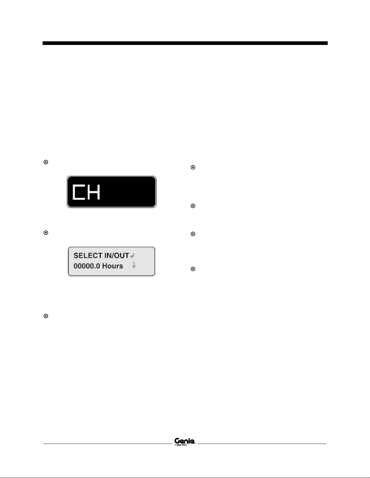
2 Press the lift function button.
On the LED screen, a circle
below the lift function symbol
will be displayed.
If the control handle is not moved within seven
seconds of pushing the lift function button, the
circle below the lift function symbol will turn off and
lift function will not operate. Press the lift function
button again.
3 Press and hold the function enable switch on
the control handle.
4 Machines equipped with foot switch: Press
and hold the foot switch and press and hold
the function enable switch on the control
handle at the same time.
5 Move the control handle in the direction
indicated by the markings on the control panel.

Operator's Manual First Edition • First Printing
Operating Instructions
44 GS™-1432m • GS™-1932m Part No. 1307419GT
To Steer
1 Press the drive function button. On the LED
screen, a circle below the drive function
symbol will turn on.
If the control handle is not moved within seven
seconds of pushing the drive function button, the
circle below the drive function symbol will turn off
and drive function will not operate. Press the drive
function button again.
2 Press and hold the foot switch (if equipped).
3 Turn the steer wheels with the
thumb rocker switch located on
the top of the control handle.
To Drive
1 Press the drive function button. On the LED
screen, a circle below the drive function
symbol will turn on.
If the control handle is not moved within seven
seconds of pushing the drive function button, the
circle below the drive function symbol will turn off
and drive function will not operate. Press the drive
function button again.
2 Machines equipped with foot switch: Press
and hold the foot switch and press and hold
the function enable switch on the control
handle at the same time.
3 Increase speed: Slowly move the control
handle off center.
Decrease speed: Slowly move the control
handle toward center.
Stop: Return the control handle to center or
release the function enable switch.
Use the color-coded direction arrows on the
platform controls and on the platform to identify the
direction the machine will travel.
Machine travel speed is restricted when the
platform is raised.
Battery condition will affect machine performance.
Machine drive speed and function speed will drop
when the battery level indicator is flashing.

First Edition • First Printing Operator's Manual
Operating Instructions
Part No. 1307419GT GS™-1432m • GS™-1932m 45
To select drive speed
The drive controls can operate in two different
drive speed modes. When the drive speed button
light is on, slow drive speed mode is active. When
the button light is off, fast drive speed mode is
active.
Press the drive speed button to select
the desired drive speed.
Note: When the platform is elevated,
the drive speed button light is always
on, indicating elevated drive speed.
Driving on a slope
Determine the slope and side slope ratings for the
machine and determine the slope grade.
Maximum slope rating, stowed position:
GS-1432m, GS-1932m
25%
14°
Maximum side slope rating, stowed position:
GS-1432m, GS-1932m
25%
14°
Note: Slope rating is subject to ground conditions
with one person in the platform and adequate
traction. Additional platform weight may reduce
slope rating.
To determine the slope grade:
Measure the slope with a digital inclinometer OR
use the following procedure.
You will need:
carpenter’s level
straight piece of wood, at least 3 feet/1 m long
tape measure
Lay the piece of wood on the slope.
At the downhill end, lay the level on the top edge
of the piece of wood and lift the end until the piece
of wood is level.
While holding the piece of wood level, measure
the vertical distance from the bottom of the piece
of wood to the ground.
Divide the tape measure distance (rise) by the
length of the piece of wood (run) and multiply by
100.
Example:
Piece of wood = 144 inches (3.6 m)
Run = 144 inches (3.6 m)
Rise = 12 inches (0.3 m)
12 in ÷ 144 in = 0.083 x 100 = 8.3% grade
0.3 m ÷ 3.6 m = 0.083 x 100 = 8.3% grade
If the slope exceeds the maximum slope or side
slope rating, then the machine must be winched or
transported up or down the slope. See Transport
and Lifting section.
Operator's Manual First Edition • First Printing
Operating Instructions
46 GS™-1432m • GS™-1932m Part No. 1307419GT
Operational indicator codes
If the platform controls LED or ground controls
LCD diagnostic readout displays an operational
indicator code such as LL, the fault condition must
repaired or removed before resuming machine
operation. Push in and pull out the red Emergency
Stop button to reset the system.
LED Readout
LCD Readout
Operational Indicator Codes
Code
Condition
LL
Off-Level
OL
Platform Overloaded
CH
Chassis Mode Operation
PHS
Pothole Guard Stuck
ND
No Drive (option)
BR
Brakes Released
Ld
Lifting Disabled
OHL
Outdoor Height Limit
For further information, please consult the
appropriate Genie Service Manual. A code and a
description of a code can also be viewed at the
ground controls LCD display.
Platform Overload
If the platform controls LED diagnostic readout
displays a flashing OL and the ground controls
LCD diagnostic readout displays OL: Platform
Overloaded, the platform is overloaded and no
functions will operate. An alarm will sound.
1 Push in the red Emergency Stop button to the
off position.
2 Remove weight from the platform.
3 Pull out the red Emergency Stop button to the
on position.
LED Readout
LCD Readout
When the platform is being raised or lowered, a
self-check function will be performed near
maximum height. The machine may stop and an
alarm may sound. If the machine is not
overloaded, normal operation will resume.
Overload Recovery
If the ground controls LCD diagnostic readout
displays Overload Recovery, the auxiliary lowering
system has been used while the platform was
overloaded. For information on how to reset the
message, please consult the appropriate Genie
Service Manual.

First Edition • First Printing Operator's Manual
Operating Instructions
Part No. 1307419GT GS™-1432m • GS™-1932m 47
Tilt Sensor Activation Settings
Tilt Sensor Activation Settings
Chassis Angle (side to side)
1.5°
Chassis Angle (front to back)
3°
If the tilt alarm sounds while
raising the platform, lower the
platform and move the machine to
a firm, level surface. If the tilt
alarm sounds when the platform is
raised, use extreme caution to
lower the platform.
When the platform controls LED
readout displays LL, the ground
controls LCD displays LL:
Machine Tilted, and the tilt alarm
sounds at 180 beeps per minute,
the following functions are
affected: drive, steer, and elevate
functions are disabled.
Return the machine to level ground to restore lift
functions.
Operation from Ground with
Controller
Maintain safe distances between the operator,
machine and fixed objects.
Be aware of the direction the machine will travel
when using the controller.
Battery Level Indicator
Use the LED diagnostic readout to determine the
battery level.
Note: When a blinking LO code appears on the
platform controls LED display, the machine must
be taken out of service and charged, otherwise all
machine functions will be disabled.
Full Charge
Half Charge
Low Charge
LO Flashing

Operator's Manual First Edition • First Printing
Operating Instructions
48 GS™-1432m • GS™-1932m Part No. 1307419GT
How to Use the Safety Arm
1 Raise the platform approximately 8ft/2.4 m to
13 ft/4.0 m from the ground.
2 Rotate the safety arm up from chassis and rest
it on the support.
3 Lower the platform until the safety arm rests
securely on the link. Keep clear of the safety
arm when lowering the platform.
How to Fold Down the Guardrails
The platform railing system consists of three fold
down rail sections for the extension deck and three
sections for the main deck. All six sections are
held in place by four wire lock pins.
1 Fully lower the platform and retract the
platform extension.
2 Remove the platform controls.
3 From inside the platform, remove the two front
wire lock pins.
4 Fold down the front rail assembly. Keep hands
clear of pinch points.
5 Replace the two removed pins back into each
side rail bracket.
6 Fold down each side rail assembly. Keep
hands clear of pinch points.
7 At the rear of the main deck, remove the two
wire lock pins.
8 Carefully open the gate and move to the
ground.
9 Fold down the rear gate and entry side rails as
one unit. Keep hands clear of pinch points.
10 Fold down the left and right side rails. Keep
hands clear of pinch points.
11 Replace the two removed pins back into each
side rail bracket.
How to Raise the Guardrails
Follow the fold down instructions but in reverse
order, ensuring all lock pins are in place and
installed properly.
First Edition • First Printing Operator's Manual
Operating Instructions
Part No. 1307419GT GS™-1432m • GS™-1932m 49
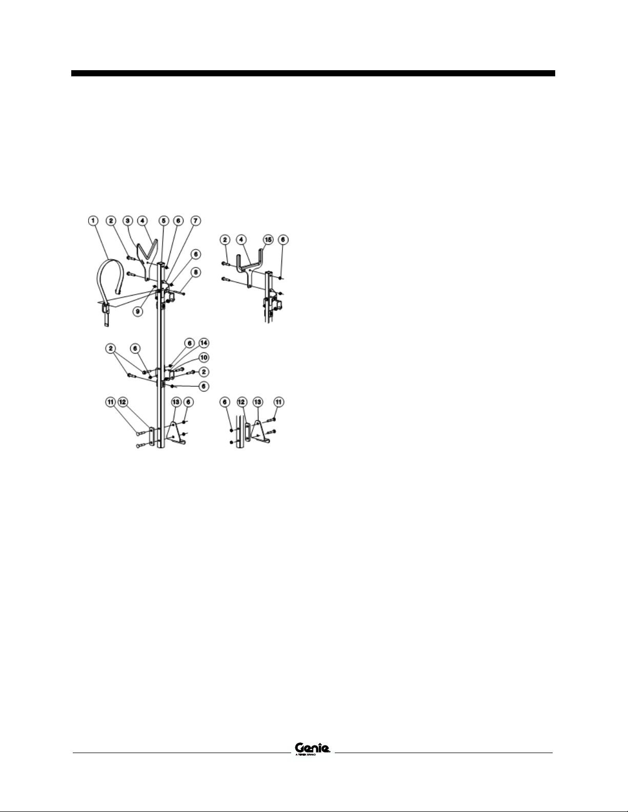
Lift Tools Pipe Cradle
Instructions
The Lift Tools Pipe Cradle assembly consists of
2 pipe cradles positioned at either side of the
platform and mounted to the guardrails with Ubolts.
1 strap
2 bolt, 3/8-16 x 2"
3 cradle
4 edge trim
5 cap
6 nut, 3/8-16
7 strap brace
8 bolt, 1/4-20 x 3.25"
9 nut, 1/4-20
10 pin bracket
11 carriage bolt, 3/8-16 x 2.25"
12 spacer
13 foot mount
14 rubber bumper
15 large pipe cradle
Observe and Obey:
Lift Tools Pipe Cradle must be mounted on the
inside of the platform.
Lift Tools Pipe Cradles cannot be used with
any other option, except Lift Tools Work Tray
and Lift Guard Contact Alarm.
Lift Tools Pipe Cradles must not obstruct the
platform controls or the platform entrance.
Lift Tools Pipe Cradle assembly is restricted to
indoor use only.
Platform is restricted to one person when Lift
Tools Pipe Cradles option is in use.
The bottom foot mount of the Lift Tools Pipe
Cradles tube must rest on the platform toeboard.
Be sure the Lift Tools Pipe Cradles is secured
to the platform.
Lift Tools Pipe Cradle Installation
1 Slide the railing mounting brackets until the
rubber bumper lands on the railings.
2 Tighten the bolts on foot mount bracket.
3 Tighten the bolts on railing mounting brackets.

Operator's Manual First Edition • First Printing
Operating Instructions
50 GS™-1432m • GS™-1932m Part No. 1307419GT
Lift Tools Pipe Cradle Operation
1 Place the load so that it rests in both Lift Tools
Pipe Cradles. The length of the load should be
parallel with the length of the platform and
centered between the Lift Tools Pipe Cradles.
2 Secure the load to each Lift Tools Pipe Cradle.
Pass the nylon strap over the load. Depress
the buckle and slide the strap through. Tighten
the strap.
3 Gently push and pull on the load to make sure
the Lift Tools Pipe Cradles and load are
secure.
4 Keep the load secured when the machine is
moving.
The The Lift Tools Pipe Cradles assembly weighs
assembly weighs 25 lbs/11.4 kg.
Maximum Lift Tools Pipe Cradles Capacity
GS-1432m, GS-1932m
215 lbs
97.5 kg
Tip-over hazard. The weight of the Lift Tools
Pipe Cradle assembly and the load in the Lift
Tools Pipe Cradle assembly will reduce the
rated platform capacity of the machine and
must be factored into the total platform load.
Tip-over hazard. The weight of the Lift Tools
Pipe Cradle assembly and the load in the Lift
Tools Pipe Cradle may limit the maximum
number of occupants in the platform.
Large pipe cradle capacity: 6” Maximum diameter.
See load chart for weight capacity.
Do not operate unless you are adequately
instructed and are aware of all hazards associated
with lifting pipes.
Do not cause a horizontal force or side load to the
machine by raising or lowering a fixed or
overhanging load.
Do not transport the unit with Lift Tools Pipe
Cradles installed. Remove entire assembly before
transporting the unit.
Panel Carrier Instructions
The Lift Tools Panel Carrier assembly consists of
a carrier assembly and a strap assembly.
1 carrier
2 carriage bolt, 1/4-20 x 0.75"
3 nut, 1/4-20
4 bolt, 3/8-16 x 2.25"
5 strap
6 bolt, 1/4-20 x 0.75"
7 nut, 3/8-16
8 anchor, strap
9 decal, warning

First Edition • First Printing Operator's Manual
Operating Instructions
Part No. 1307419GT GS™-1432m • GS™-1932m 51
Observe and Obey:
Lift Tools Panel Carrier must be mounted on
the left side of the platform.
Lift Tools Panel Carrier cannot be used with
any other option, except Lift Tools Work Tray.
Lift Tools Panel Carrier must not obstruct the
platform controls or the platform entrance.
Lift Tools Panel Carrier is restricted to indoor
use only.
The platform is restricted to one person when
Lift Tools Panel Carrier option is in use.
Be sure that the Lift Tools Panel Carrier is
secured to the platform.
Panel Carrier Installation
1 Hang carrier (1) onto the bottom flange of the
platform, on the left side.
2 Secure the carrier with 2, 1/4" carriage bolts
(2) and lock nuts (3).
3 Attach mounting tab (8) to front rail post. A
3/8" bolt (4) and nut (7) are provided.
4 Attach strap (5) to mounting tab.
Installation of Panel Carrier Strap
1 Open the clamp and install it on the mounting
tab with the 1/4" x 0.75" bolt (6).
2 Install the strap assembly end plate onto the
bolt.
3 Insert the bolt through the other side of the
clamp.
Panel Cradle Operation
1 Place the load so that it rests in the center of
the Lift Tools Panel Carrier.
2 Secure the load to the platform using the strap
by passing it in front of the load and securing
the S-hook around the upper rail near the rear
of the platform.
3 Gently push and pull on the load to make sure
the panel carrier and load are secure.
4 Keep the load secured when the machine is
moving.
The Lift Tools Panel Carrier assembly weighs
22 lbs/10 kg.
Maximum Lift Tools Panel Carrier Capacity
Load Chart
GS-1432m, GS-1932m
100 lbs
45.4 kg
Tip-over hazard. The weight of the Lift Tools
Panel Carrier assembly and the load in the Lift
Tools Panel Carrier assembly will reduce the
rated platform capacity of the machine and
must be factored into the total platform load.
Tip-over hazard. The weight of the Lift Tools
Panel Carrier assembly and the load in the Lift
Tools Panel Carrier may limit the maximum
number of occupants in the platform.
Maximum panel size allowed: 4 feet high x
8 feet long. See load chart for weight capacity.
Do not operate unless you are adequately
instructed and are aware of all hazards associated
with lifting panels.
Do not cause a horizontal force or side load to
machine by raising or lowering a fixed or
overhanging load.
Do not transport the unit with Lift Tools Panel
Carrier installed. Remove entire assembly before
transporting the unit.

Operator's Manual First Edition • First Printing
Operating Instructions
52 GS™-1432m • GS™-1932m Part No. 1307419GT
Lift Tools Work Tray Instructions
The Lift Tools Work Tray assembly consists of one
tray and two mounting brackets with hardware.
1 bolt, 1/4-20 x 0.75"
2 rubber bumper
3 lift tool work tray
4 tool tray bracket
5 decal, warning
Observe and Obey: Lift Tools
Work Tray Installation
Lift Tools Work Tray must be installed on the
inside of the platform.
Only one Lift Tools Work Tray can be used per
machine.
Mount Lift Tools Work Tray on the Extension
Deck rail on the opposite side of the PCON.
Lift Tools Work Tray can be on either upper or
lower rail.
Be sure the Lift Tools Work Tray is secured to
the platform.
Lift Tools Work Tray lanyard is for tools only.
Do not attach personal safety lanyard.
Lift Tools Work Tray Installation
1 Tighten the four 1/4-20 x 0.75 bolts (1).

First Edition • First Printing Operator's Manual
Operating Instructions
Part No. 1307419GT GS™-1432m • GS™-1932m 53
Lift Tools Work Tray Operation
1 Place the load so that it rests inside the Lift
Tools Work Tray.
The Lift Tools Work Tray assembly weighs
4 lbs/1.8 kg.
Maximum capacity of Lift Tools Work Tray is
50 lbs/23 kg.
Tip-over hazard. The weight of Lift Tools Work
Tray assembly and the load in the Lift Tools
Work Tray assembly will reduce the rated
platform capacity of the machine and must be
factored into the total platform load.
Platform Height Restriction
Instructions
Platform Height Restriction allows the platform to
be limited to a specific height.
Observe and Obey: Platform
Height Restriction
Read, understand and obey all warnings and
instructions provided with the Platform Height
Restriction.
Platform Height Restriction
Operation
To limit height:
Note: The User Max Height option must be turned
on. See Service and Repair manual.
1 Raise the platform to the desired maximum
height with the platform control.
2 Press and hold the lift function selection button
on the platform control for 5 seconds.
3 The maximum platform height limit is activated
when:
a The platform control LED displays
“LoHt”, and
b The alarm beeps 7 times.
4 Perform function tests prior to use.

Operator's Manual First Edition • First Printing
Operating Instructions
54 GS™-1432m • GS™-1932m Part No. 1307419GT
To remove the height limit:
1 Turn the key switch to platform control.
2 Pull out the red Emergency Stop button to the
on position at the ground controls.
3 Pull out the red Emergency Stop button to the
on position at the platform controls.
4 Press and hold the lift function selection button
for 5 seconds, at any height.
5 The maximum platform height limit has been
removed when:
a The platform control LED displays
“FLHt”, and
b The alarm beeps 7 times.
To test the platform height restriction:
1 Press and hold the lift function enable button,
and press the platform up button.
Result: The platform should raise to the
previously set height. After reaching the
maximum height restriction, platform
movement will stop. If the operator continues
holding the joystick in the elevate direction for
more than 2 seconds after reaching the
maximum platform height limit, the platform
alarm will beep for one second and LoHt is
displayed on the platform controls LED.
Note: The User Max Height option must be turned
on and a height must have previously been set.

First Edition • First Printing Operator's Manual
Operating Instructions
Part No. 1307419GT GS™-1432m • GS™-1932m 55
Battery and Charger Instructions
Observe and Obey:
Do not use an external charger or booster
battery.
Charge the battery in a well-ventilated area.
Use proper AC input voltage for charging as
indicated on the charger.
Use only a Genie authorized battery and
charger.
To Charge Battery
1 Be sure the batteries are connected before
charging the batteries.
2 Open the battery compartment. The
compartment should remain open for the
entire charging cycle.
Maintenance-free batteries
1 Connect the battery charger to a grounded AC
circuit.
2 The charger will indicate when the battery is
fully charged.
Standard Batteries
1 Remove the battery vent caps and check the
battery acid level. If necessary, add only
enough distilled water to cover the plates. Do
not overfill prior to the charge cycle.
2 Replace the battery vent caps.
3 Connect the battery charger to a grounded AC
circuit.
4 The charger will indicate when the battery is
fully charged.
5 Check the battery acid level when the charging
cycle is complete. Replenish with distilled
water to the bottom of the fill tube. Do not
overfill.
After Each Use
1 Select a safe parking location—firm level
surface, clear of obstruction and traffic.
2 Lower the platform.
3 Turn the key switch to the off position and
remove the key to secure from unauthorized
use.
4 Charge the batteries.

Operator's Manual First Edition • First Printing
Transport and Lifting Instructions
56 GS™-1432m • GS™-1932m Part No. 1307419GT
Transport and Lifting Instructions
Observe and Obey:
Genie provides this securement information as
a recommendation. Drivers are solely
responsible for making sure machines are
properly secured and the correct trailer is
selected pursuant to US Department of
Transportation regulations, other localized
regulations, and their company policy.
Genie customers needing to containerize any
lift or Genie product should source a qualified
freight forwarder with expertise in preparing,
loading and securing construction and lifting
equipment for international shipment.
Only qualified mobile elevating work platform
operators should move the machine on or off
the truck.
The transport vehicle must be parked on a
level surface.
The transport vehicle must be secured to
prevent rolling while the machine is being
loaded.
Be sure the vehicle capacity, loading surfaces
and chains or straps are sufficient to withstand
the machine weight. Genie lifts are very heavy
relative to their size. See the serial label for
the machine weight.
The machine must be on a level surface or
secured before releasing the brakes.
Do not allow the rails to fall when the snap
pins are removed. Maintain a firm grasp on the
rails when the rails are lowered.
Do not drive the machine on a slope that
exceeds the uphill, downhill or side slope
rating. See Driving on a Slope in the Operating
Instructions section.
If the slope of the transport vehicle bed
exceeds the uphill or downhill maximum slope
rating, the machine must be loaded and
unloaded using a winch or forklift as described
in the brake release operation. See the
Specifications section for the slope ratings.
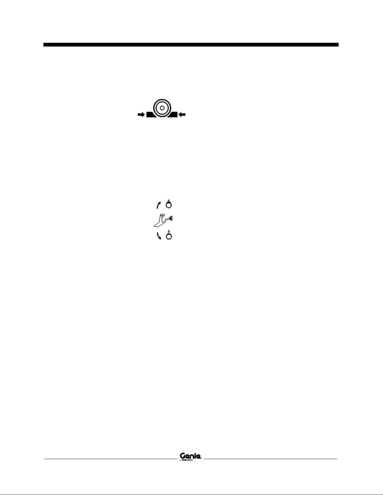
First Edition • First Printing Operator's Manual
Transport and Lifting Instructions
Part No. 1307419GT GS™-1432m • GS™-1932m 57
Brake Release Operation, Electric
Drive Option
1 Chock the wheels or
tracks to prevent the
machine from rolling.
2 Be sure the winch line is properly secured to
the drive chassis tie points and the path is
clear of all obstructions.
3 Pull out the red Emergency Stop button at
both the ground and platform controls and
position the key switch to ground mode.
4 Locate the brake release switch, located under
the rear end of the right forklift pocket.
5 Remove the protective cover
from the toggle switch.
6 Move the toggle switch as
indicated in the image to
engage the brakes. The alarm
will turn on when the brakes
are released.
After the machine is loaded:
1 Chock the wheels to prevent the machine from
rolling.
2 Pull out the red Emergency Stop button at
both the ground and platform controls to the
on position.
3 Press and hold the drive/steer function enable
switch on the control handle. Move the control
handle off center and immediately release it to
reset the brakes.
4 Push the red Emergency stop button at both
the ground and platform controls to the off
position.
Towing the Genie GS1432m and GS1932m is not
recommended. If the machine must be towed, do
not exceed 2 mph/3.2 km/h.

Operator's Manual First Edition • First Printing
Transport and Lifting Instructions
58 GS™-1432m • GS™-1932m Part No. 1307419GT
Securing to Truck or Trailer for
Transit
Always use the extension deck lock when the
machine is transported.
Turn the key switch to the off position and remove
the key before transporting.
Inspect the entire machine for loose or unsecured
items.
Use chains or straps of ample load capacity.
Use a minimum of 2 chains or straps.
Adjust the rigging to prevent damage to the
chains.

First Edition • First Printing Operator's Manual
Transport and Lifting Instructions
Part No. 1307419GT GS™-1432m • GS™-1932m 59
Observe and Obey:
Only qualified riggers should rig and lift the
machine.
Only qualified forklift operators should lift the
machine with a forklift.
Be sure the crane capacity, loading surfaces
and straps or lines are sufficient to withstand
the machine weight. See the serial label for
the machine weight.
Lifting the Machine with a Forklift
Be sure the extension deck, controls and
component trays are secure. Remove all loose
items on the machine.
Fully lower the platform. The platform must remain
lowered during all loading and transport
procedures.
Use the forklift pockets from the rear of the
machine.
Position the forklift forks in position with the forklift
pockets.
Drive forward to the full extent of the forks.
Raise the machine 16 in / 0.4 m and then tilt the
forks back slightly to keep the machine secure.
Be sure the machine is level when lowering the
forks.
Lifting the machine from the
bottom can result in component
damage.

Operator's Manual First Edition • First Printing
Transport and Lifting Instructions
60 GS™-1432m • GS™-1932m Part No. 1307419GT
Lifting Instructions
Fully lower the platform. Be sure the extension
deck, controls and component trays are secure.
Remove all loose items on the machine.
Determine the center of gravity of your machine
using the table and the picture on this page.
Attach the rigging only to the designated lifting
points on the machine. There is a 2.5 cm hole at
each corner of the drive chassis for lifting.
Adjust the rigging to prevent damage to the
machine and to keep the machine level.
Center of Gravity Table (Actual dimensions may
vary due to machine configuration, options, and
manufacturing tolerances)
Model
X Axis
Y Axis
GS-1432m
21.85 in
55.5 cm
19 in
48.3 cm
GS-1932m
21.85 in
55.5 cm
18 in
45.7 cm
1
X Axis
2
Y Axis
First Edition • First Printing Operator's Manual
Maintenance
Part No. 1307419GT GS™-1432m • GS™-1932m 61
Maintenance
Observe and Obey:
Only routine maintenance items specified in
this manual shall be performed by the
operator.
Scheduled maintenance inspections shall be
completed by qualified service technicians,
according to the manufacturer’s specifications
and the requirements specified in the
responsibilities manual.
Use only Genie approved replacement parts.
Maintenance Symbols Legend
The following symbols have been used in this
manual to help communicate the intent of the
instructions. When one or more of the symbols
appear at the beginning of a maintenance
procedure, it conveys the meaning below.
Indicates that tools will be required to
perform this procedure.
Indicates that new parts will be required to
perform this procedure.
Check the Hydraulic Oil Level
Maintaining the hydraulic oil at the proper level is
essential to machine operation. Improper hydraulic
oil levels can damage hydraulic components. Daily
checks allow the inspector to identify changes in
oil level that might indicate the presence of
hydraulic system problems.
1 Be sure that the machine is on a firm, level
surface, free of obstructions, with the platform
in the stowed position.
2 Visually inspect the oil level in the hydraulic oil
tank.
Result: The hydraulic oil level should be
between the ADD and FULL marks on the tank.
3 Add oil as needed. Do not overfill.
Hydraulic oil specifications
Hydraulic oil type
Chevron Rando HD equivalent
Note: For cold weather operation and information
on alternative hydraulic fluids, please refer to the
Genie Scissor Maintenance Manual.

Operator's Manual First Edition • First Printing
Maintenance
62 GS™-1432m • GS™-1932m Part No. 1307419GT
Check the Batteries
Proper battery condition is essential to good
machine performance and operational safety.
Improper fluid levels or damaged cables and
connections can result in component damage and
hazardous conditions.
Electrocution hazard. Contact with hot or live
circuits may result in death or serious injury.
Remove all rings, watches and other jewelry.
Bodily injury hazard. Batteries contain acid.
Avoid spilling or contacting battery acid.
Neutralize battery acid spills with baking soda
and water.
Note: Perform this test after fully charging the
batteries.
1 Put on protective clothing and eye wear.
2 Be sure that the battery cable connections are
tight and free of corrosion.
3 Be sure that the battery hold-down brackets
are in place and secure.
Note: Adding terminal protectors and a corrosion
preventative sealant will help eliminate the
corrosion on the battery terminals and cables.
Scheduled Maintenance
Maintenance performed quarterly, annually and
every two years must be completed by a person
trained and qualified to perform maintenance on
this machine according to the procedures found in
the service manual for this machine.
Machines that have been out of service for more
than three months must receive the quarterly
inspection before they are put back into service.

First Edition • First Printing Operator's Manual
Specifications
Part No. 1307419GT GS™-1432m • GS™-1932m 63
Specifications
Model
GS-1432m
Height, working outdoor
20 ft 1 in
6.30 m
Height, platform outdoor
14 ft 1 in
4.30 m
Height, working indoor
20 ft 1 in
6.30 m
Height, platform indoor
14 ft 1 in
4.30 m
Height, stowed maximum, rails up
6 ft 2 in
1.88 m
Height, stowed maximum,
rails folded
4 ft 11 in
1.49 m
Platform height, stowed maximum
2 ft 6 in
0.78 m
Height, guard rails
3 ft 7 in
1.10 m
Width
32 in
0.81 m
Length, stowed
4 ft 7 in
1.40 m
Length, platform extended
6 ft 7 in
2 m
Platform extension length
24 in
0.60 m
Platform dimensions (length x
width)
4 ft 7 in x
30 in
1.40 m x
0.77 m
Maximum load capacity
500 lbs
227 kg
Maximum wind speed, outdoors
28 mph
12.5 m/s
Maximum wind speed, indoors
0 mph
0 m/s
Wheelbase
3 ft 8 in
1.12 m
Turning radius (outside)
4 ft 6 in
1.37 m
Turning radius (inside)
0 in
0 cm
Ground clearance
2.8 in
7 cm
Ground clearance
Pothole guards deployed
0.75 in
2 cm
Weight
1984 lbs
900 kg
(Machine weights vary with option configurations. See
serial label for specific machine weight.)
Power source
2 Batteries, 12V 115AH
System voltage
24V
Maximum hydraulic pressure
(functions)
1800 psi
124 bar
Tire size
10 x 3 in
25 x 8 cm
Total vibration value to which the hand/arm system is
subjected does not exceed 2.5 m/s2.
Highest root mean square value of weighted
acceleration to which the whole body is subjected does
not exceed 1.6 ft/s2 or 0.5 m/s2.
Ambient operating temperature
Minimum
-20°F
-29°C
Maximum
120°F
49°C
Airborne noise emissions
Sound pressure level at ground
workstation
<70 dBA
Sound pressure level at platform
workstation
<70 dBA
Maximum slope rating, stowed position
25% (14°)
Maximum side slope rating, stowed
position
25% (14°)
Note: Slope rating is subject to ground conditions with
one person in the platform and adequate traction.
Additional platform weight may reduce slope rating.
Drive speeds
Stowed, maximum
2.5 mph
4.0 km/h
Platform raised,
maximum
0.5 mph
40 ft/55 sec
0.8 km/h
12.2 m/55 sec
Floor loading information, GS-1432m
Tire load maximum
937 lbs
425 kg
Tire contact pressure
143 psi
10 kg/cm2
988 kPa
Occupied floor pressure
203 psf
1000 kg/m2
9.73 kPa
Note: Floor loading information is approximate and
does not incorporate different option configurations.
It should be used only with adequate safety factors.
Continuous improvement of our products is a Genie
policy. Product specifications are subject to change
without notice or obligation.

Operator's Manual First Edition • First Printing
Specifications
64 GS™-1432m • GS™-1932m Part No. 1307419GT
Model
GS-1932m
Height, working outdoor
23 ft 0 in
7.18 m
Height, platform outdoor
17 ft 0 in
5.18 m
Height, working indoor
24 ft 2 in
7.55 m
Height, platform indoor
18 ft 2 in
5.55 m
Height, stowed maximum, rails up
6 ft 5 in
1.97 m
Height, stowed maximum,
rails folded
5 ft 2 in
1.58 m
Platform height, stowed maximum
2 ft 10 in
0.87 m
Height, guard rails
3 ft 7 in
1.10 m
Width
32 in
0.81 m
Length, stowed
4 ft 7 in
1.40 m
Length, platform extended
6 ft 7 in
2 m
Platform extension length
24 in
0.6 m
Platform dimensions (length x
width)
4 ft 7 in x
30 in
1.40 m x
0.77 m
Maximum load capacity
500 lbs
227 kg
Maximum wind speed, outdoors
28 mph
12.5 m/s
Maximum wind speed, indoors
0 mph
0 m/s
Wheelbase
3 ft 8 in
1.12 m
Turning radius (outside)
4 ft 6 in
1.37 m
Turning radius (inside)
0 in
0 cm
Ground clearance
2.8 in
7 cm
Ground clearance
Pothole guards deployed
0.75 in
2. cm
Weight
2600 lbs
1179 kg
(Machine weights vary with option configurations. See
serial label for specific machine weight.)
Power source
2 Batteries, 12V 115AH
System voltage
24V
Maximum hydraulic pressure
(functions)
2400 psi
165.5 bar
Tire size
10 x 3 in
25 x 8 cm
Total vibration value to which the hand/arm system is
subjected does not exceed 2.5 m/s2.
Highest root mean square value of weighted
acceleration to which the whole body is subjected does
not exceed 1.6 ft/s2 or 0.5 m/s2.
Ambient operating temperature
Minimum
-20°F
-29°C
Maximum
120°F
49°C
Airborne noise emissions
Sound pressure level at ground
workstation
<70 dBA
Sound pressure level at platform
workstation
<70 dBA
Maximum slope rating, stowed position
25% (14°)
Maximum side slope rating, stowed
position
25% (14°)
Note: Slope rating is subject to ground conditions with
one person in the platform and adequate traction.
Additional platform weight may reduce slope rating.
Drive speeds
Stowed, maximum
2.5 mph
4.0 km/h
Platform raised,
maximum
0.5 mph
40 ft/55 sec
0.8 km/h
12.2 m/55 sec
Floor loading information, GS-1932m
Tire load maximum
1257 lbs
570 kg
Tire contact pressure
164 psi
10.13 kg/cm2
1131 kPa
Occupied floor pressure
254 psf
1238 kg/m2
12.16 kPa
Note: Floor loading information is approximate and
does not incorporate different option configurations.
It should be used only with adequate safety factors.
Continuous improvement of our products is a Genie
policy. Product specifications are subject to change
without notice or obligation.
GS™-1432m • GS™-1932m
Part No. 1307419GT
Operator's Manual
First Edition • First Printing

 Loading...