

Page 1
GCL-T
Standard Duty Operator
TROLLEY
PROPER APPLICATION
Operator Type Door Type Max Door Weight/HP
Trolley Sectional 1/2HP = 1120 lbs.
(Standard, Sidemount (Standard or Low
or Dual)
Headroom Track only)
3/4HP = 1370 lbs.
1HP = 1620 lbs.
™
EZ Limit
Multivolt
TensiBelt
™
111848.501539
™
™
06-12
NOT FOR R E S I D E N T I A L USE
This Installation Manual provides the information required to install, troubleshoot and
maintain a GCL-T
™
Commercial / Industrial Door Operator.
Page 2

THIS PAGE LEFT BLANK
GCL-T
Standard Duty Operator
www.geniecompany.com 06-12
Page 3

Table of Contents
Section 1 How to use this manual .................................................1.1
Section 2 Safety Information & Instructions ................................2.1
Section 3 Critical Installation Information ............................ 3.1-3.2
Section 4 Installation ................................................................4.1-4.9
Section 5 Wiring ........................................................................5.1-5.9
Line Voltage Wiring ....................................................................5.1
Low Voltage Control Wiring ....................................................5.2
External Wire Diagram ...............................................................5.3
Wall Control ...................................................................................5.4
Interlock Switches .......................................................................5.5
Photocell Wiring ..........................................................................5.6
Sensing Edge Wiring ..................................................................5.7
External Radio Installation .......................................................5.8
Section 6 Operator Setup Procedures .....................................6.1-6.9
Setting Close Direction ...............................................................6.2
Setting Braking Rate ................................................................... 6.3
Setting Travel Limits ...................................................................6.4
Setting Limit Overrun ..................................................................6.5
Monitored Reversing Devices ..................................................6.6
Drawbar Assembly ...............................................................4.1-4.6
Attach Operator ...........................................................................4.7
Connection to the Door ............................................................4.8
Clutch Adjustment .......................................................................4.9
Connecting Motor/Safety Information ...............................5.9
Setting Open & Close Modes ...................................................6.7
(Optional) Transmitter Programming....................................6.8
Setting Mid-Stop Limit ................................................................6.9
Resetting the MRT 6.10
......................................................................
Section 7 Special Operational Features ..................................7.1-7.2
Operator Cycle Count ................................................................7.1
GDO & Display Firmware ..........................................................7.1
Operator Type............................................................................... 7.2
Section 8 Troubleshooting ......................................................8.1-8.5
Display Operation .......................................................................8.1
Error Codes .............................................................................8.1-8.2
Run Codes ...............................................................................8.2-8.3
Troubleshooting Example using Codes ..............................
LED Indicators ...............................................................................8.4
Safe-T-Beam® Troubleshooting Chart .................................8.5
Section 9 Service & Maintenance ................................................... 9.1
Preventive Maintenance Schedule .........................................9.1
Section 10
Basic Operator Parts ...............................................................10.1
Section 11 Warranty .......................................................................11.1
Appendixes ........................................................ 10.1-10.11
Appendix A ........................................................................10.1-10.9
Basic Shafts Parts ......................................................................10.3
Basic Rail Parts ......................................................................10.4
Basic Carriage/Door Arms Parts.......................................10.5
Basic Electric Box Parts ......................................................10.6
Electric Box Layout ..............................................................10.7
Appendix B ..................................................................................10.8
Screw Terminal Assignments ..........................................10.8
Appendix C ...................................................................... 10.9-10.11
Run Codes ...............................................................................10.9
Error Codes ...............................................................10.10-10.11
8.3
GCL-T
Standard Duty Operator
www.geniecompany.com 06-12
TOC
Page 4
Section 1: How to use this manual
The 11 sections of this Installation Manual provide the information required to install, troubleshoot and maintain an GCL-T™ commercial/industrial
door operator.
Section 2
Provides important defining information related to safety terminology used throughout this manual, as well as safety related instructions which
must be followed at all times while doing any steps/tasks/instructions detailed in this manual.
Section 3
Details pre-installation concerns/issues/decisions that are recommended to be considered and/or resolved prior to beginning any commercial door
operator installation.
WARNING
Sections 4-6
Provide step by step installation and set-up instructions for the GCL-T™ commercial door operator. Each section is written such that it must be
followed in a step by step order to complete a successful installation.
Sections 7-8
Detail important features and troubleshooting information for typical installation and normal operations that may occur.
Sections 9-11
Provide related information on service and maintenance items, operator drawings for use in troubleshooting and service activities, along with
important warranty and returned goods policy information.
Failure to correctly perform all steps in sections 4-6 can result in serious injury or death.
GCL-T
Standard Duty Operator
www.geniecompany.com 06-12
1.1
Page 5
Section 2: Safety Information & Instructions
WARNING
Commercial/Industrial Sectional and Rolling Steel Doors are large, heavy objects that move with the help of springs
under high tension and electric motors. Since moving objects, springs under tension, and electric motors can cause
injuries, your safety and the safety of others depend on you reading the information in this manual. If you have any
questions or do not under stand the information presented, call your nearest service representative. For the number
of your local Genie® Dealer, call 800-OK-GENIE, and for Genie® Factory Technical Advice, call 800-843-4084.
In this Manual, the words Danger, Warning, and Caution are used to stress important safety information. The word:
ER
DANG
WARNING
CAUTION
The word NOTE is used to indicate important steps to be followed or important considerations.
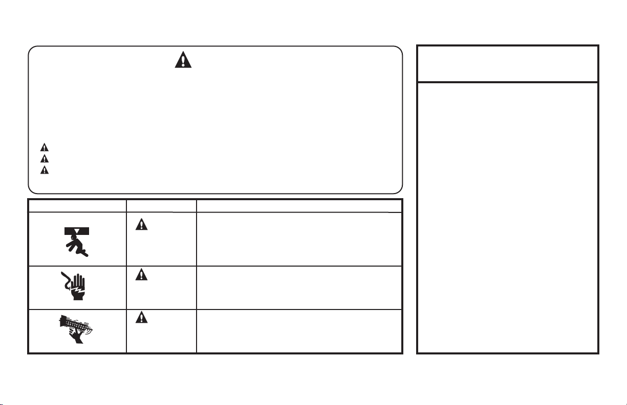
POTENTIAL HAZARD EFFECT PREVENTION
MOVING DOOR
ELECTRICAL SHOCK
HIGH SPRING TENSION
indicates an imminently hazardous situation which, if not avoided, will result in death or serious injury.
indicates a potentially hazardous situation which, if not avoided, could result in death or serious injury.
indicates a potentially hazardous situation which, if not avoided, may result in injury or property damage.
Do Not operate unless the doorway is in sight and free of
WARNING
Could result in
Serious Injury
or Death
WARNING
Could result in
Serious Injury
or Death
WARNING
Could result in
Serious Injury
or Death
obstructions. Keep people clear of opening while door is moving.
Do Not allow children to play with the door operator.
Do Not change operator control to momentary contact unless an
external reversing means is installed.
Do Not operate a door that jams or one that has a broken spring.
Turn off electrical power before removing operator cover.
When replacing the cover, make sure wires are not pinched or near
moving parts.
Operator must be electrically grounded.
Do Not try to remove, repair or adjust springs or anything to which
door spring parts are fastened, such as, wood block, steel bracket,
cable or any other structure or like item.
Repairs and adjustments must be made by a trained service
representative using proper tools and instructions.
IMPORTANT
READ PRIOR TO ANY DOOR OPERATION
1. Read manual and warnings carefully.
2. Keep the door in good working condition.
Periodically lubricate all moving parts of door.
3. If door has a sensing edge, check
operations monthly. Make any necessary
repairs to keep it functional.
4. AT LEAST twice a year, manually operate
door. The Door should open and close freely.
If it does not, the door must be taken out of
service and a trained service representative
must correct the condition causing
the malfunction.
5. The Operator Motor is protected against
overheating by an internal t
If
the operator ceases to function because
motor protector has tripped, a trained service
technician may need to correct the condition
which caused the overheating. When motor
has cooled, thermal protector will
automatically reset and normal operation can
be resumed.
6. In case of power failure, the door can be
operated manually by pulling the release
cable to disconnect the operator drive system.
7. Keep instructions in a prominent location
near the pushbutton.
hermal protector.
GCL-T
Standard Duty Operator
www.geniecompany.com 06-12
2.1
Page 6
Section 3: Critical Installation Information
Job Site Issues to Consider/Concerns
The following list of items should be considered prior to selecting an operator for a given job site.
1-Available power supply.
2-Type of door.
3-Potential operator mounting obstructions. Items to consider include, but are not limited to: side room, room above door shaft,
surface integrity, power supply location, and convenient chain hoist and release cable positioning.
4-Size of door for appropriate
6-Door activation needs/requirements. Examples include 3
key switches, etc. See “Entrapment Protection” section below.
7-Interlock switches are required under certain conditions for
ENTRAPMENT PROTECTION
The installation of a fail safe external reversing device (such as a monitored reversing edge or photocell system) is required on all momentary contact electronically
operated commercial doors. If such a reversing device is not installed, the operator will revert to a constant contact control switch for operation (Closing only).
The Reversing Devices currently UL Approved with are:
1)
MillerEdge ME, MT and CPT series monitored edge sensors used in combination with Timer-Close Module P/N OPABTCX.S or OPAKMEIGX.S INTERFACE MODULE.
2) Residential Safe-T-Beam® Monitored Photocells from The Genie® Company, model OSTB-BX (P/N 38176R).
3) Series II Commercial Safe-T-Beam®, Monitored Photocells P/N OPAKPE.S.
4) Series II Commercial Safe-T-Beam®, Monitored Photocells for NEMA4, P/N OPAKPEN4GX.S.
operator torque and door travel speed selection.
button control stations, 1 button control stations, radio controls, pull
and corrosiveness of the location.
ssenitsud ,ssenpmad dna noitacol rotarepo edulcni redisnoc ot smetI .tnemnorivne gnitnuom rotarepO-5
rof deriuqer( smaeb llecotohp ro/dna segde gnisrever era selpmaxE .tnempiuqe yrosseccA-8
.5.5 egap eeS .skcol rood dna srood ssap htiw srood
room below door shaft, available mounting
cords,
loop detectors, photoelectric controls,
.cte ,sthgil gninraw ,syaler lortnoc yrailixua,),tcatnoc yratnemom sa etarepo ot tes srood
WARNING:
CAUTION:
Check working condition of door before installing the operator. Door must be free from sticking and binding. If equipped, deactivate
any door locking device(s). Door repairs and adjustments, including cables and spring assemblies MUST be made by a trained service
representative using proper tools and instructions.
GCL-T
Standard Duty Operator
DO NOT apply line voltage until instructed to do so.
www.geniecompany.com 06-12
3.1
Page 7
Section 3: Critical Installation Information
ENTRAPMENT PROTECTION
UNTIL ONE OF THESE MONITORED EXTERNAL ENTRAPMENT DEVICES IS INSTALLED, TH .NOITCERID ESOLC EHT NI NOITAREPO TCATNOC YRATNEMOM WOLLA TON LLIW
APPROVED DEVICES
Miller Edge ME, MT & CPT series monitored edge sensors used in combination with either the Genie®
Timer-Close Module or Direct connect through STB inputs.
Safe-T-Beam® from Genie®—P/N 38176R.
Commercial Monitored PhotoeyeKit—P/N OPAKPE.S.
Commercial NEMA4 Monitored Photocells—P/N OPAKPEN4GX.S.
GCL-J&H 1/2
GCL-J&H 3/4
GCL-J&H 1
T=Trolley
Note: Total door weight, and not the square footage, is the critical factor in selecting the proper operator.
Square footage measurements are based on "square doors." (Example=16' x 16')
NOTE: Doors that require special windloading and wide doors, normally require increased strutting (reinforcement). Strutting doors can significantly increase door
weight beyond weight shown. Consult Customer Service for the impact of wind load andstrutting on square foot limits.
NOTE: "PU-FIP" stands for "polyurethane, foamed-in-place." If no notation is present, insulation is "polystyrene, layed-iin-place."
Sectional Door Chart (sq. ft.)
Door S e ries ->
UL L is tedHPMod el
Ye s TSC 1120 256 220 370 256 440 340 320 320 256 360 400 300 400 380 360 240
Ye s
Ye s
Mounting
Type
TSC 1370 330 256 440 310 530 400 320 320 256 450 450 370 460 440 400 330
TSC 1620 380 280 500 370 570 410 320 320 256 480 480 420 500 480 400 400
216 216 ins. 220 220 ins. 2415 2415 ins. 2411 2411 ins. 125 150 200 200-20 5150 5200 451 452
Max.
16GA.
Door
Flush
Weight
Steel
(Lbs)
CommercialSteelInsulated&Non-Insulated Thermospan Thermomark
20GA.
Ribbed
Steel
20GA.
Ribbed
Steel
Insulated
16GA.
Flush
Steel
Insulated
E OPERATOR
24GA.
24GA.
Ribbed
Ribbed
Steel
Insulated
Steel
Nominal
24GA.
Ribbed
Steel
Nominal
24GA.
Ribbed Steel
Insulated
ALLOWABLE DOOR WIDTH
ANY WIDTH
30 FEET
30 FEET
30 FEET
PU/FIP
Insulated
1.38"
PU/FIP
Insulated
2"
PU/FIP
Insulated
PU/FIP
Insulated
2"
20GA.
Exterior
PU/FIP
Insulated
Raised
Panel
1.38"
PU/FIP
Insulated
Raised
Panel
2"
1/8" Glass
1.38"
Aluminum
1/4" or 1/2"
.0102 ,92 tsuguA gnitrats evitca stnemeriuqer 523LU htiw ecnailpmoc ni secived tnempartne detsiL LU gniwollof eht htiw desu eb nac ™T-LCG ehT
Glass
1.38"
GCL-T
Standard Duty Operator
www.geniecompany.com 06-12
3.2
Page 8
Section 4: Installation
IMPORTANT
INSTALLATION INSTRUCTIONS
WARNING -
To reduce the risk of severe injury or death:
1) READ AND FOLLOW ALL INSTALLATION INSTRUCTIONS.
2) Install only on a properly operating and balanced door. A door that is operating
improperly could cause severe injury. Have qualified service personnel make
repairs to cables, spring assemblies and other hardware before installing the operator.
3) Remove all pull ropes and remove, or make inoperative, all locks (unless mechanically
and/or electronically interlocked to the power unit) that are connected to the door
before installing the operator.
4) Install the door operator at least 8 feet above the floor if the operator has exposed
moving parts.
5) Do not connect the door operator to the power source until instructed to do so.
6) Locate the control station: (a) within sight of the door, (b) a minimum of 5 feet above
the floor so that small children cannot reach it, and (c) away from all moving parts
of the door.
7) Install the Entrapment Warning Placard next to the control station and in a
prominent location.
8) For products having a manual release, instruct the end user on the operation of the
manual release.
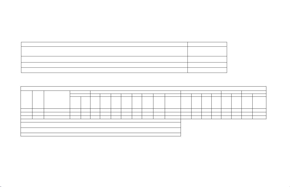
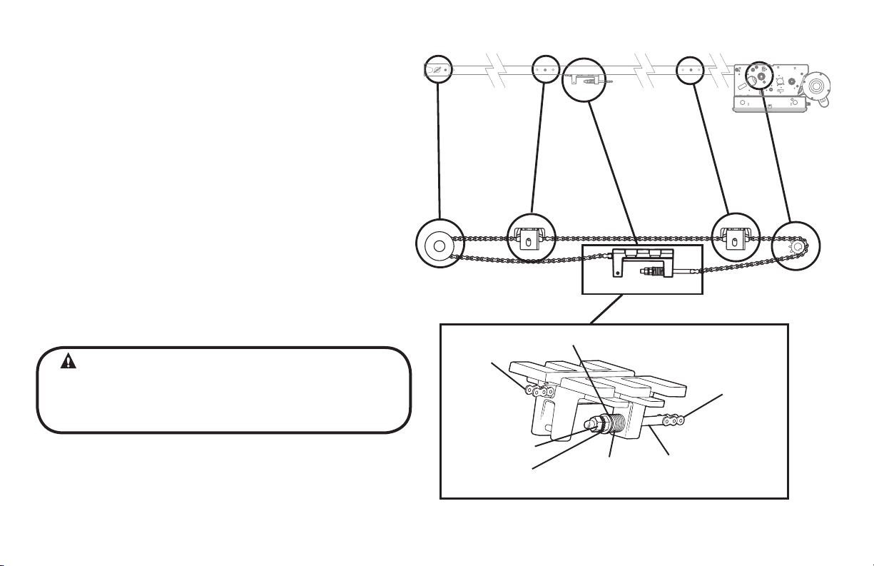
Drawbar Assembly
The Drawbar Operator consists of the Power Unit (A), Drawbar Rail
(B), Chain Guides (C), Front Spreader (D), Front Idler Pulley (E), Drive Chain (F), Drive
Sprocket (G) and Drawbar Arm (H). The Drawbar rail length, chain length and
quantity of chain guides will vary by door heights. Fig. 1.
NOTE: Drawbar rail must be (29) inches longer than the door’s height. Rails
have been sized properly and pre-punched for the chain guide assemblies from
the factory.
Figure 1
D
E
C
B
F
G
A
GCL-T
Standard Duty Operator
www.geniecompany.com 06-12
4.1
Page 9
Drawbar Assembly (continued)
1) Attach Rails to Power Unit using four (4) 7/16”-14 x 1” bolts,
7/16”-14 keps nuts and 7/16” lock washers (provided). Fig. 2.
2) Attach the chain guide assemblies to the drawbar rails using
Track Bolts and locknuts (provided). Fig. 3.
CAUTION
Verify that screws are properly seated in track. Failure to seat screws can
cause carriage to bind in door track.
Figure 2
7/16"
BOLTS
NOTE: Space chain guides evenly between operator and header. Add a chain
guide for every 4 feet of door height per chart.
UNDER 12’
2 3 4 5
NOTE: Chain Guide mounting holes have been pre-drilled at standard locations along the track. If different locations are needed, hole size should be
1/4" dia. Be sure to de-burr the holes.
Figure 3
12’ to 16’ 16’ to 20’ 20’ to 24’
PLASTIC CHAIN GUIDE
CHAIN GUIDE BRACKET
GCL-T
Standard Duty Operator
TRACK BOLTS/
LOCKNUTS
www.geniecompany.com 06-12
4.2
Page 10
Drawbar Assembly (continued)
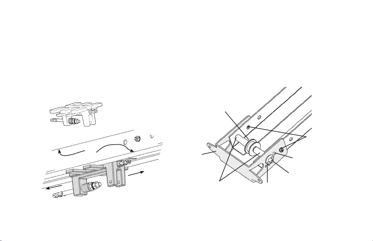
3) Insert the carriage into the rails as shown in Fig. 4.
NOTE: The end of the carriage with the chain tension adjustment bolt should be
toward the operator.
4) Place the spreader bracket in position around the drawbar rail. Do not
will be held in place (temporarily) by the clevis pin which holds
the pulley.
5) Install the idler pulley inside the rails by inserting the 3/8” x 4-1/2” clevis
pin through one of the rails and as you feed it through an idler
sleeve and the idler pulley followed by the second sleeve . Place fender
washer (7/16” x 1-1/4”) over end of clevis pin. Secure clevis pin using
cotter pin. Fig. 5.
redaerps ehT .emit siht ta stun kcol dna stlob kcart eht tresni
bracket
NOTE: For building of the spreader bracket assembly on a Dual Trolley unit see
the separate Drawbar instruction sheet for Sidemount and Dual Trolley models.
OPERATOR
GCL-T
Standard Duty Operator
RAIL
CARRIAGE
Figure 4
IDLER PULLEY
FRONT
SPREADER
BRACKET
DOOR
SLEEVE
WASHER
CLEVIS PIN
Figure 5
www.geniecompany.com 06-12
LOCKNUTS
DO NOT INSTALL YET!
COTTER PIN
/STLOB KCART
4.3
Page 11
Drawbar Assembly (continued)
6) Uncoil the drawbar chain and install by routing the chain over the chain
guides (A) and around the drive sprocket (B) on the output shaft as shown
in Fig. 6.
7) Attach to Chain Tension Adjusting Bolt (C) using a master link (provided).
8) Pass the other end of the chain between the front spreader bracket and
the idler pulley (D). Make certain the chain is not twisted.
9) Attach the chain to the carriage (E) using a master link.
10) Insert the Adjusting Bolt through the hole in the Carriage and place the
tensioning spring, flat washer and adjusting nut onto the bolt. Detail A,
Fig 6.
11) Tighten Chain so that it will not jump a sprockets or pulley. Add locknut.
Check to ensure the following:
• The chain is properly engaging the output sprocket.
• The chain is not twisted.
D
Figure 6
A
A
B
E
C
WARNING
• DO NOT apply line voltage until instructed to do so.
• Repairs and adjustments, including particularly to cables and spring
assemblies under high tension, must be made by a trained service
representative using proper tools and instructions.
GCL-T
Standard Duty Operator
www.geniecompany.com 06-12
Detail A
MASTER
LINK
FLAT WASHER
LOCKNUT
ADJUSTING NUT
TENSIONING
SPRING
MASTER
LINK
CHAIN
TENSION
ADJUSTMENT
SCREW
4.4
Page 12
Drawbar Installation
CAUTION
Check the working condition of the door before installing the operator. The
Door must be free from sticking and binding. If the door is equipped with a
latching device, secure the locking bar in the open (unlocked) position. This
style operator will act as a latching device when the door is down and
therefor the door’s lock is no longer needed.
If the door lock is to remain functional, an interlock switch MUST be installed
which will prevent operation of the door whenever the door lock is engaged.
Refer to the Wiring Instructions, section 5.5, of this manual for proper
connection of the interlock switch.
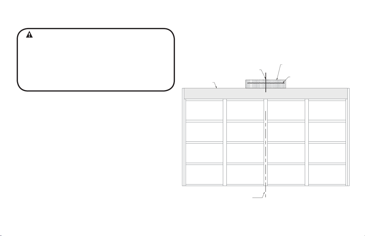
1) Measure the width of the door to determine the center. Make a vertical
line above the door, as shown in Fig. 7. (If the vertical line is not in line
with a door stile, a means of attaching the door bracket to the door must
be provided. This can be accomplished by spanning the center of the
door’s top section (between the top and bottom rail) with a suitable
material such as wood or steel).
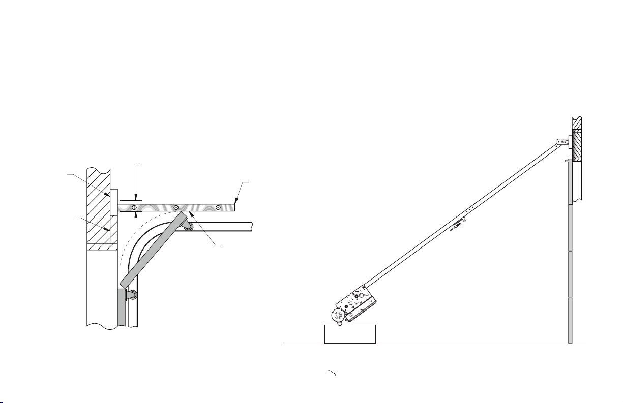
2) Prepare for attaching drawbar to header. If woodwork, or other suitable
material is not already in place, securely affix a 2” x 6” block of wood or
metal plate as shown in Fig. 7.
3) Center the block/plate on the header.
4) Mark the door’s vertical center line on this block/plate.
5) Use a level, as shown in Fig. 8 (pg 4.6) to find the highest point of travel for
the door.
6) Mark a horizontal line across the vertical line you made on the header
at 5” above the highest point of door travel.
NOTE: On torsion spring doors with an uneven number of panels, the operator
may be attached to the stile nearest to the center.
VERT CAL L NE
(SEE STEP 1)
HEADER
CENTERLINE
OF DOOR
ATTACHMENT MATER AL
(SEE STEP 2)
HOR ZONTAL L NE
(SEE STEP 6)
Figure 7
GCL-T
Standard Duty Operator
www.geniecompany.com 06-12
4.5
Page 13
Drawbar Installation (continued)
7) Raise the door end (idler pulley) of the drawbar while resting the operator
on the floor or other desired material.
8) Position the spreader bracket on your centerline with its bottom edge on
your horizontal mark. Fig. 9.
• Fasten spreader bracket to header using fasteners appropriate for the
header material.
MARK A HORIZONTAL LINE
ABOVE HIGHEST POINT OF TRAVEL
2" X 6"
HEADER
5"
LEVEL
HIGHEST POINT
OF TRAVEL
GCL-T
Standard Duty Operator
Figure 8
Figure 9
www.geniecompany.com 06-12
4.6
Page 14
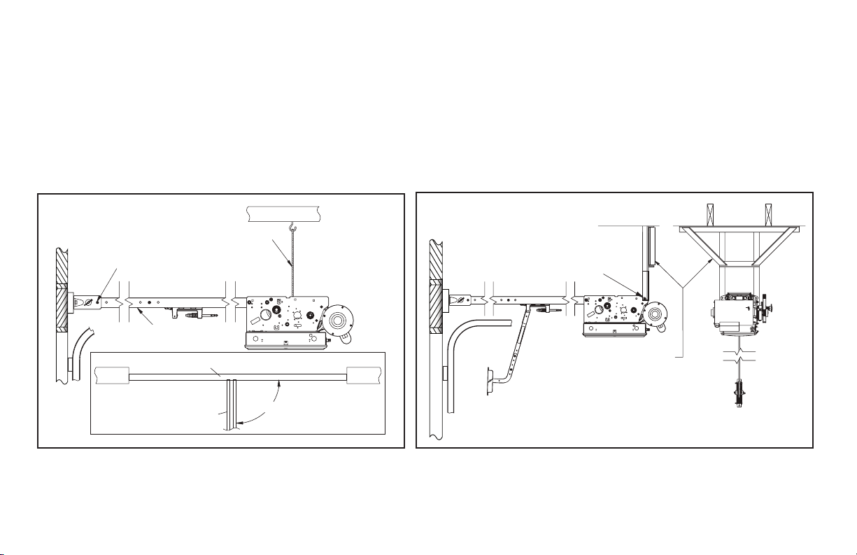
Attach Operator
1) Raise the operator and position it so that the drawbar rails are
level and perpendicular to the face of the door (or the stile where
the door bracket will be attached). Fig. 10.
2) Lock the drawbar rails into the spreader bracket using the
track bolts (1/4”-20 X 9/16”) and two(2) locknuts.
3) Secure the operator in position by installing steel angles (not
provided) between the ceiling superstructure and the operator
power unit. Fig. 11.
two (2)
Figure 10
TRACK BOLTS
& LOCK NUTS
LEVEL
WALL WALL
ROPE, CABLE,
CHAIN, ETC.
DOOR FROM ABOVE
RAILS
90°
NOTE: Track bolts MUST be installed from inside the rails.
Figure 11
DRILL HOLE IN ANGLE
AND MOUNT USING
REAR SUPPORT
CARRIAGE BOLT
STEEL
ANGLES
(NOT INCLUDED)
GCL-T
Standard Duty Operator
www.geniecompany.com 06-12
4.7
Page 15
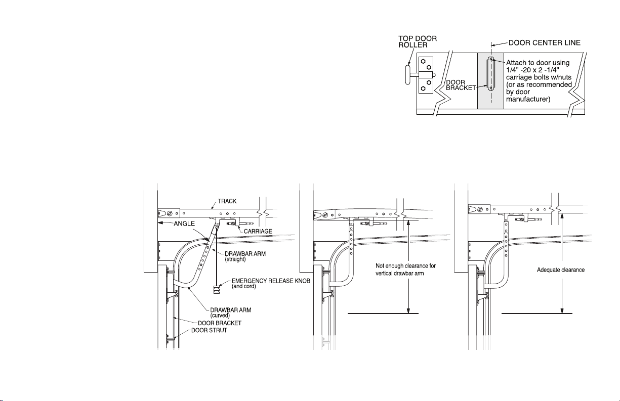
Connection to the Door
1) Pull down on the drawbar arm locking sleeve and attach to carriage. (See NOTE 2.)
2) Position the door bracket on the door as shown in Fig. 11, with mounting
. ) holes on the door centerline. (Even with or above top door roller
3) For wood doors fasten the door bracket to the door using two 1/4” -20 X 2-1/4”
carriage bolts and nuts. For metal doors use two 1/4”- 20 self tapping sheet
metal screws, or as recommended by the door manufacturer.
4) Use two (2) 3/8” -16 X 7/8” bolts and nuts to attach the door arms together.
NOTE: Use the set of holes that align the drawbar in a near vertical position for operators
without a brake. Set arms at a 20-30 degree rearward angle for operators with a brake.
Fig. 12.
For units without a brake, set arms as close to 0 degrees (vertical) as possible.
NOTE: If the door strut interferes with the mounting of the door bracket, position
the door bracket below the strut. DO NOT, in any way, cut or modify the strut.
Figure 11
NOTE 2: In case of emergency, pulling the Emergency
Release Knob (Fig. 12) disengages the door from operator
allowing for the door to be shut manually.
Figure 12
When installing non-brake units
with drawbar near vertical, it is
important to make sure there
is adequate room between the
door bracket and drawbar rail
for the door arms to go vertical.
Without sufficient clearance
and by running the dood arms
vertical, a significant amount of
force could be applied possibly
leading to damage.
There is an optional drawbar
kit with a cusion springbox
available: P/N OPAKDBT.S
GCL-T
Standard Duty Operator
WITH BRAKE WITHOUT BRAKE
AVOID THIS SETUP
20°-30°
with Brake
www.geniecompany.com 06-12
WITHOUT BRAKE
CORRECT
4.8
Page 16
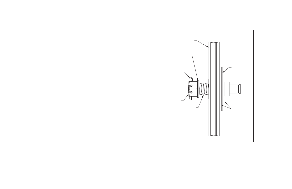
Clutch Adjustment Fig. 13
The Operators have a friction style clutch that can be adjusted.
NOTE: The clutch is intended to provide protection for the door, the operator and
yellorT .noitcetorp tnempartne rof dednetni ton si tI tnempiuqe detaicossa
operators have a motor reversing feature that is integrated with the clutch
assembly. If an obstruction is placed in the pathway of the door during operation
the motor will stop and reverse when the clutch begins to slip.
The adjustment of the clutch should be such that the door and operator function in
this manner. The steps for clutch adjustment follow:
CLUTCH PULLEY
WASHER
To Adjust the Clutch
1) Decrease the compression on the clutch until the operator will not lift
the door.
• Turn the adjusting castle nut counter-clockwise to decrease clutch
compression and clockwise to increase clutch compression.
2) After completing step 1, begin to increase compression on the
clutch until the operator is capable of lifting the door through the
complete cycle
3) Test the reversing feature of the operator by placing an obstruction
under the door during a close cycle. The door should reverse on the
obstruction and return to the open position. If the door does not
close but comes down part way and reverses without any
obstructions in its path, then increase the clutch compression until
the door will close fully.
4) Finally, insert the cotter pin through the castle nut and shaft and bend
the outer leg of the cotter pin.
NOTE:
Periodically check the system for proper clutch action. If clutch starts to slip after
working properly for some time, check manual operation of door BEFORE adjusting
clutch. The door may not be operating freely or the counterbalance spring may
need adjusting. Repairs and adjustments must be performed by a trained service
representative using proper tools and instructions.
GCL-T
Standard Duty Operator
without clutch slippage.
www.geniecompany.com 06-12
COTTER PIN
ADJUSTING NUT
Figure 13
SPRING
CLUTCH
PAD
CLUTCH
PLATE
4.9
Page 17
Section 5: Wiring
Line Voltage Wiring Fig. 1
WARNING
• DO NOT apply power to operator until instructed to do so.
• The Genie® Company recommends that line voltage wiring
be performed by a qualified electrician.
• Be sure that electrical power has been disconnected from the
input power wires being connected to the operator prior to
handling these wires. An appropriate lock-out /tag-out procedure
is recommended.
• Line voltage wiring must meet all local building codes.
• Make sure operator voltage, phase and frequency nameplate
ratings are identical to the job site line voltage ratings.
• Input power wiring must be properly sized for the operators
amperage rating located on the nameplate.
• To reduce the risk of electric shock, make sure the chassis of this
unit is properly grounded.
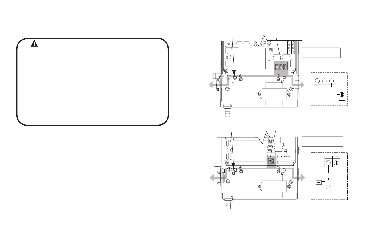
1) Remove LINE VOLTAGE INPUT PLUG and install proper
fittings and 1/2”conduit.
2) Route proper LINE VOLTAGE wires into operator.
3) Locate LINE INPUT terminals on circuit board. Using
correct connectors, attach wires to LINE INPUTS, and GROUND
terminal.
• Keep low
• Route all line voltage wires as shown.
• Plug all unused conduit holes.
voltage and line voltage wires separate.
Figure 1
HIGH
VOLTAGE
INPUT PLUGS
(Right & Left)
HIGH
VOLTAGE
INPUT PLUGS
(Right & Left)
LINE INPUT
TERMINALS
LINE INPUT
TERMINALS
P
LINE
GROUND
ROUTE HIGH VOLTAGE WIRING
IN THE SHADED AREA AS SHOWN
LINE
GROUND
Three Phase
LINE IN
POWER CONNECTIONS
1
2
LINE 1
LINE 2 L NE 3
GND
LINE IN
Single Phase
POWER CONNECTIONS
N/ 2
LINE
NEU RAL
5V
(HO
LINE
LINE 2
208V
230V
GND
GCL-T
Standard Duty Operator
ROUTE HIGH VOLTAGE WIRING
IN THE SHADED AREA AS SHOWN
www.geniecompany.com 06-12
5.1
Page 18

Low Voltage Control Wiring (general) Fig. 2
1) Connect all LOW VOLTAGE control circuit wires to this end
of the unit using 1/2” conduit or flexible convoluted tubing.
• Keep low voltage and line voltage wires separate.
• Route all low voltage control wiring as shown. This includes
all control circuit wires such as wall controls, timers and single
button input devices as well as radio control and safety
circuit wiring. See Figs 2 through 10 in this section.
• Plug all unused conduit holes.
NOTE: For a detailed description of control wire terminals see Appendix B.
LOW
VOLTAGE
INPUT
PLUGS
(Left &
Right)
ROUTE LOW VOLTAGE WIRING
IN THE SHADED AREA AS SHOWN
Optional
Accessory
Modules
GCL-T
Standard Duty Operator
Figure 2
www.geniecompany.com 06-12
LOW VOLTAGE
CONTROL WIRE
TERMINALS
5.2
Page 19

3-BUTTON
STATION
OPEN
CLOSE
STOP
REMOVE
JUMPER
IF STOP
BUTTON
IS USED
*
See Appendix B for detailed description of terminals.
External Wire Diagram
EXT
EXT
N-O
N-O
ODC
ODC
1-BTNGNDSTOPCLOSEOPEN
STB
1-BTN
STATION
N/O
KEY
SWITCH
STATION
N/O
CARD
READER
N/O
O/C
PULL
SWITCH
N/O
REVERSE
REVERSE
STB
INTLK
INTLK
REMOVE
JUMPER
WHEN
INSTALLING
EXTERNAL
INTERLOCK
SENSING EDGE SWITCH
(DO NOT CONNECT
2-WIRE MONITORED
SENSING EDGE SWITCH
TO THESE INPUTS)
PWR
20-40 VDC @ 250mA
MAX CURRENT
EXT RADIO CONNECTOR
ORANGE
BLUE
NOM
+ 24VDC
YELLOW
RELAY
GND
RADIO
Located inside
Electrical Box
*
GCL-T
MULTIPLE
3-BUTTON
STATION
INSTALLATIONS
REQUIRE THE
STOP BUTTON
TO BE WIRED
IN SERIES.
See Fig. 5, pg 5.4
Standard Duty Operator
*
SERIES II SAFE-T-BEAM®
(STB)
(*CONNECT STB WIRES
TO EITHER TERMINAL)
SIGNATURE
MODULE
+
-
THRU-BEAM PHOTOCELLS
+
-
2-WIRE MONITORED SENSING EDGE SWITCH
www.geniecompany.com 06-12
5.3
Page 20

Wall Control
WARNING:
the user and is far enough from the door, or positioned such that
the user is prevented from coming in contact with the door while
operating the controls .
• Attach the Warning placard adjacent to the Wall Control. Fig. 3A.
• Wall Control(s) must be located so that the door is within sight of
WARNING:
If momentary contact control is to be used, an external reversing device such
as a photocell system or sensing edge switch must be used. See pages
5.6-5.7 for installation of entrapment protection devices.
Figure 3
Figure 3A
11 735
CONTROL SIGNAL TERMINAL STRIP
OPEN CLOSE STOP GND
NOTE:
JUMPER BETWEEN
STOP AND GND
TERMINALS MUST
BE REMOVED
Entrapment
Warning
Placard
3-BUTTON
STAT ON
OPEN
CLOSE
STOP
1) For a single 3 - button installation, make connections as
shown in Fig. 3.
2) For single button accessory controls, make connections as
shown in Fig. 4.
3) For a multiple 3 - button installations, make connections as
shown in Fig. 5.
NOTE: If an External STOP button is NOT being installed, a jumper wire
must be installed between the “STOP” AND “GND” terminals as shown.
NOTE: Long Distance Relay Kit wiring is not required for long
distance control runs and should not be used
GCL-T
Standard Duty Operator
www.geniecompany.com 06-12
Figure 4
CONTROL SIGNAL TERMINAL STRIP
GNDSTOP 1-BTN
ODC
STB
1-BTN
STAT ON
KEY
SW TCH
STAT ON
CARD
READER
OPEN/CLOSE
PULL SW TCH
CONTROL SIGNAL TERMINAL STRIP
OPEN CLOSE STOP GND
OPEN
CLOSE
STOP
3-BUTTON
STAT ON
Figure 5
NOTE:
JUMPER BETWEEN
STOP AND GND
TERM NALS MUST
BE REMOVED
OPEN
CLOSE
STOP
3-BUTTON
STAT ON
5.4
Page 21

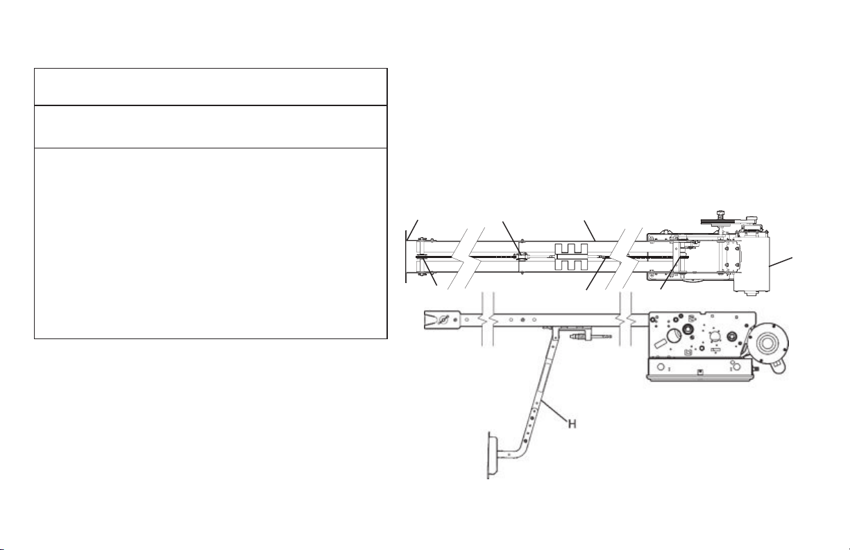
Interlock Switches (Wall Mount)
1) Optional external interlock switches are
required with some Sectional or Rolling Steel
Doors to prevent the door from operating
under certain conditions including
the following:
• If the door is equipped with a
functioning door lock, an interlock
switch (A) must be installed to prevent
electric operation when the lock
is engaged.
• If the door is equipped with a pedestrian
pass-through door, an interlock switch (B)
must be installed at the pass-through
door in order to prevent electrical
operation when the pass-through door
is open.
2) The Switches must be set in the field.
GCL-T
Standard Duty Operator
Figure 6
NOTE: If External Interlock is used, THE JUMPER WIRE BETWEEN THE
EXT INTLK TERMINALS MUST BE REMOVED.
SWITCH
075412-0000.S
(N.O.)
B
Pass door interlock:
Should be open when
door is open.
Closed when door
is closed.
ANGLE
405964-0000.S
TRACK
A
Side lock interlock:
Should be engaged when door is locked.
Disengaged when door is unlocked.
www.geniecompany.com 06-12
CONTROL SIGNAL TERMINAL STRIP
EXT
NTLK
STANDARD
SLIDELOCK
SWITCH (N.C.) P/N 110324.0001.S
For Sectional Door
Left-hand P/N 110325.0001.S
For Rolling Steel Door
EXT
NTLK
5.5
Page 22

Photocell Wiring
Series II Safe-T-Beam® Monitored Photocells
1) Monitored SERIES II (STB) Residential Safe-T-Beam® Photocells
NOTE: Installer must enable ODC STB in calibration mode. See page 6.9.
override external reversing devices, including photocells.
2) To Mount Photocells: (Kit includes detailed Instructions).
Determine location for mounting. They do not need to be directly adjacent to
the door but must be somewhere along the wall where there will be an
unobstructed line between them. Fig 9.
breaks the plane of the photo-beam.
WARNING:
mounted near the doorway in such a way that the lower portion of an individual’s
leg will break the photocell beam during normal walking conditions. If an
alternative location is chosen it must be approved by the facility owner.
Commercial Non-Monitored Photocells
1) Nominal 24 Volt DC Commercial photocells with normally open contacts can be
connected as shown in Fig. 8.
NOTE: Blue wire supplies 20 – 40VDC. Photocells used must be compatible with this
voltage range.
NOTE: If no voltage is present at Blue wire, check fuse F-1 on
from Genie® (P/N 38176R.S) Fig. 7. Wiring to these photocells can
be connected to either terminal (they are not polarity sensitive.
( Troubleshooting in Section 8)
WARNING:
Actuating operator using constant contact on the CLOSE button will
.
They must extend out away from the wall sufficiently that no door hardware
Photocell systems provide entrapment protection when
Control board.
Figure 7
Figure 8
Figure 9
CONNECT WIRES TO EITHER TERMINAL
(NOT POLARITY SENSITIVE)
SERIES II (STB)
RESIDENTIAL SAFE-T-BEAM™
CONTROL SIGNAL
TERMINAL STRIP
N-O
N-O
REVERSE
REVERSE
+
RECEIVER
-
THRU-BEAM
PHOTOCELLS
ODC
STB
EXT RADIO CONNECTOR
+
TRANSMITTER
-
ODC
STB
PWR
20 40 VDC @ 250mA
MAX CURRENT
Blue
Orange
RELAY
NOM
+24VDC
RADIO
CONTROL SIGNAL
TERMINAL STRIP
Yellow
GND
GCL-T
Standard Duty Operator
www.geniecompany.com 06-12
5.6
Page 23

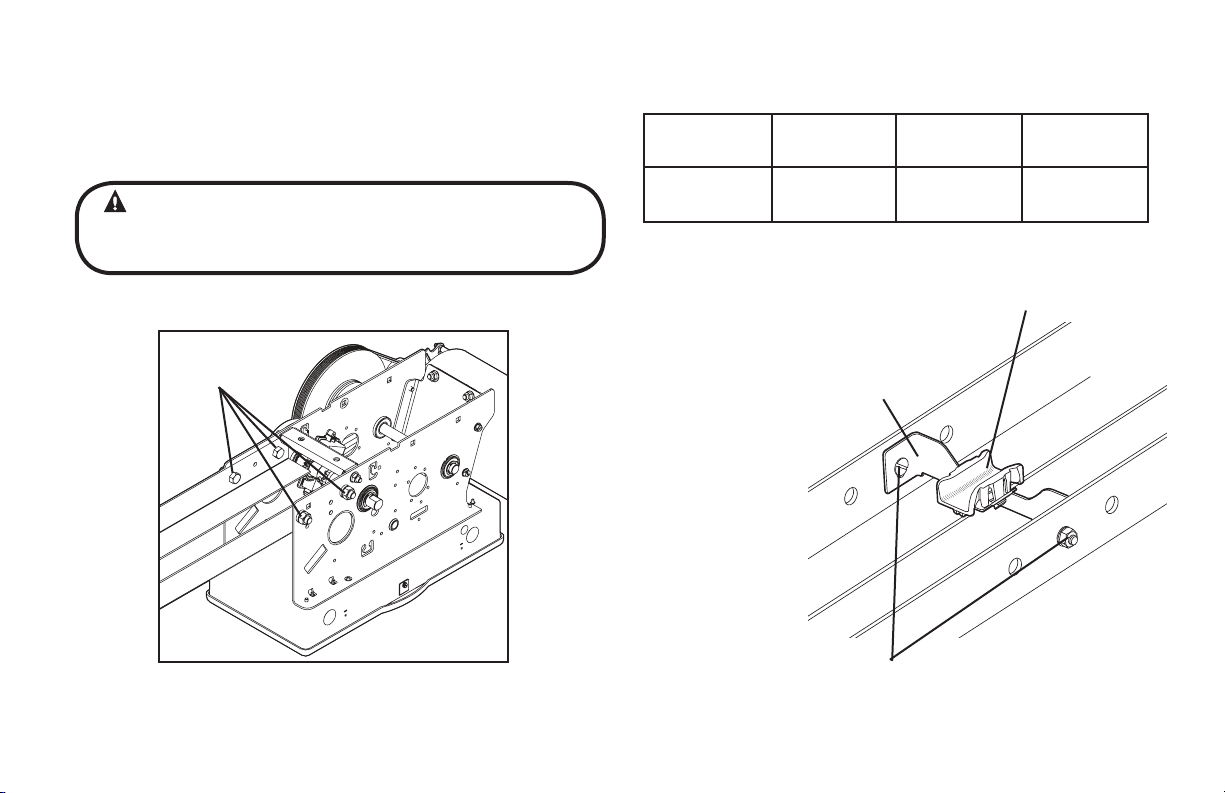
Sensing Edge Switch Installation
Figure 11 shows an example of a typical sensing edge installation. Left hand side is shown but
right hand is a mirror image of this.
1A) If wiring from sensing edge switch to operator is coiled cord or 2 wire jacketed cord:
• Install junction box 12” above the center of the door opening on same side as
sensing switch.
• Secure one end of cord to junction box using a cable clamp.
1B) If connection is to be made through a take up reel cord:
• Install on same side as sensing edge switch and above door opening and
slightly to the side.
• Install junction box adjacent to take up reel and route the stationary cord from
the reel to the box and secure with a cable clamp.
NOTE: Do not use a take-up-reel on a monitored edge. They have slip connections in them
that momentarily break contact which causes false reversals.
2) Secure other end of cord (straight, coiled or reel) to sensing edge switch
enclosure using a cable clamp.
3) Connect wires of cord to sensing edge switch using wire nuts or other suitable
wire connectors.
4) Run a straight 2 wire cord from the junction box (Step 1)
electrical
box.
to the operator
• Secure using cable clamp on each end.
5) Join wires in cord from operator to wires in cord from switch using wire nuts or
other suitable wire connectors.
6A) Non-Monitored sensing or reversing edge connects to terminal strip on main board
using N-O reverse inputs. See Fig. 10A.
6B) Monitored sensing or reversing edge connects to Timer-Close Module terminals
or to terminal strip on main board through MillerEdge Signature Module SM-101
as shown in Fig. 10B.
7) Operate the door to make certain cord is free to travel and does not become
snared during door opening or closing.
• Check sensing edge switch for proper operation.
Figure 10A
NOTE derotinom-noN
sensing edge can be
connected directly to
CONTROL SIGNAL
these terminals. DO NOT
connect a 2-wire Monitored
sensing edge switch to
these terminals.
Figure 10B
NOTE::
2-wire monitored
sensing edge switch
must be connected
through the MillerEdge
Signature Module SM-101.
SIGNATURE MODULE
TIMER-CLOSE MODULE TERMINAL STRIP
NOTE Monitored 2-wire
sensing or reversing
edge can also be used
in combination with a
Timer-Close Module.
Figure 11
N-O
REVERSE
ODC
STB
MON
EDGE
TERMINAL STRIP
N-O
REVERSE
SENSING EDGE SWITCH
TERMINAL STRIPCONTROL SIGNAL
ODC
STB
SENSING EDGE SWITCH
GND
SENSING EDGE SWITCH
WARNING:
Actuating the operator using constant contact on the CLOSE
button will override external reversing devices, including sensing edges or
reversing edges.
GCL-T
Standard Duty Operator
www.geniecompany.com 06-12
5.7
Page 24

External Radio Installation
Although the GCL-T™ Operators are equipped with an internal radio, they also
provide a universal connection for an external radio.
To Add the External Radio
1) Plug the 3-wire pigtail (provided) onto the plug connector marked
“EXT RAD.” Fig. 12.
2) Make wiring connections to the pigtail.
GCL-T
Standard Duty Operator
Optional
Accessory
Modules
F1 (.25A)
Figure 12
www.geniecompany.com 06-12
EXTERNAL
RADIO
CONNECTOR
PWR
20-40 VDC @ 250 mA
MAX. CURRENT
EXT RADIO CONNECTOR
Blue
Orange
RELAY
NOM
+24VDC
RADIO
Yellow
GND
5.8
Page 25

WARNING:
Verify Line Voltage before making any connections to assure that
motor harness is connected to proper motor connector on
circuit board.
1) Plug motor harness into proper motor connector on circuit board
in electric box. Fig. 13.
2) Apply primary power.
Figure 13
SINGLE PHASE
THREE PHASE
208/
240V
208/
240V
120V
480/
575V
Motor
Connectors
To reduce the risk of severe injury or death:
1) READ AND FOLLOW ALL INSTRUCTIONS.
2) Never let children operate or play with door controls. Keep the remote control (where
provided) away from children.
3) Personnel should keep away from a door in motion and keep the moving door in
sight until it is completely closed or opened. NO ONE SHOULD CROSS THE PATH OF
A MOVING DOOR.
4) Test the door’s safety features at least once a month. After adjusting either the force
or the limit of travel, retest the door operator’s safety features.
5) For products having a manual release, if possible, use the manual release only when
the door is closed. Use caution when operating the release while the door is open.
Weak or broken springs may cause the door to fall rapidly, causing severe injury
or death.
6) KEEP DOOR PROPERLY OPERATING AND BALANCED. See Door Manufacturer’s
Owner’s Manual. An improperly operating or improperly balanced door could cause
severe injury or death. Have only trained door systems technicians make repairs to
cables, spring assemblies, other hardware and any wooden blocks or like items to
which they may be attached.
7) SAVE THESE INSTRUCTIONS.
DANGER: After power is supplied to the operator, Do
Not make contact with components inside the control panel
except for the Keypad Keys. Fig. 1.
IMPORTANT
SAFETY INSTRUCTIONS
WARNING -
GCL-T
Standard Duty Operator
www.geniecompany.com 06-12
5.9
Page 26

Section 6: Operator Setup Procedure
Control Panel
The operators include a full function control panel including a liquid crystal
display (LCD), calibration keys and Open, Close and Stop keys for on board
operator control. See Fig. 1. The open, close and stop keys function as a 3-button
wall control. The Display will show current operator conditions and calibration
information. Due to limited character space, some displays will be abbreviated.
See Appendix C (pgs. 10.9-10.10) for full display descriptions.
Operators also include a non-volatile memory. The unit will remember all
calibration settings plus error code and run code logs, if power is removed from
unit.
DANGER: After power is supplied to the operator, Do Not make
contact with components inside the control panel except for the Keypad
Keys. Fig. 1.
Control Operating Modes
Operator control boards operate in two modes: Run Mode and Calibration
Mode.
The control board should normally operate in the Run Mode. The operator
is calibrated in Calibration Mode.
With the operator standing idle:
PRESS CAL/RUN TO TOGGLE BETWEEN OPERATING MODES.
• The first display in calibration mode is “SET CLOSE DIR.”
• The display in run mode will be one of the condition codes listed
in Appendix C.
Calibration & Run
Mode Toggle Key.
Display Backlighting
Toggle Key.
Operation Keys, operate
unit like a 3-button
wall station.
LCD DISPLAY
CAL
RUN
Scroll Keys, used in
Calibration Mode.
SCROLL
SCROLL
SET
CLEAR
Set/Clear Key, used to
reset and adjust
calibration settings.
OPEN
CLOSE
STOP
WARNING: DO NOT calibrate operator or operate door unless
doorway is in sight and free of obstructions. Keep people clear of
opening while door is moving.
GCL-T
Standard Duty Operator
www.geniecompany.com 06-12
Figure 1
6.1
Page 27

Setting Close Direction
The direction of motor rotation depends on mounting position and/or how the
main input power phases are wired. This setting is used to insure the door is
closing and opening according to the input commands.
1) If operator is in RUN mode, press CAL/RUN to enter calibration mode.
2) Press SET/CLEAR to begin the calibration procedure and advance to
SET
CLEAR
CAL
RUN
the next screen. Figure 3.
3 ) Briefly press the CLOSE key. (Pressing the Scroll key at this point will exit
CLOSE
this control function.)
• The display will read “ DID DOOR CLOSE? “ Figure 4.
4) Press SCROLL key (up or down) to toggle between YES and NO.
SCROLL
Figure 5.
• If YES is selected, no change to operator calibration is made. If
NO is selected — the POD will change the operator’s down direction.
5) Press the SET/CLEAR key.
6) Press CAL/RUN to return to run mode.
SET
CLEAR
CAL
RUN
Figure 2
Figure 3
Figure 4
Figure 5
SCROLL KEY
SET CLOSE DIR
CAL SET
RUN
SCROLL
SCROLL
CLEAR
HIT CLOSE KEY
CAL
RUN
SCROLL
SCROLL
SET
CLEAR
DID DOOR CLOSE?
CAL
RUN
SCROLL
SCROLL
SET
CLEAR
YES NO
CAL
RUN
SCROLL
SCROLL
SET
CLEAR
OPEN
CLOSE
STOP
OPEN
CLOSE
STOP
OPEN
CLOSE
STOP
OPEN
CLOSE
STOP
GCL-T
Standard Duty Operator
www.geniecompany.com 06-12
6.2
Page 28

Setting Braking Rate (optional)
CAL
1) If operator is in RUN mode, press CAL/RUN to enter calibration mode.
2) Press Scroll until display reads “BRAKING RATE >#.” where # is the
deceleration rate, ranging from 0 to 9. 0=max. braking. 9=Min.
Figure 6.
3) Press SET/CLEAR key to toggle between 0 and 9—one digit at a time.
SET
CLEAR
4) Pick a value and operate the door. Adjust as necessary.
5) Press a SCROLL key to shift to a new function and lock in the setting.
6) Press CAL/RUN to return to run mode.
SCROLL
CAL
RUN
RUN
BRAKING RATE 0
CAL
RUN
Figure 6
SCROLL
SCROLL
SET
CLEAR
OPEN
CLOSE
STOP
GCL-T
Standard Duty Operator
www.geniecompany.com 06-12
6.3
Page 29

Setting Travel Limits
UP and/or DOWN
1) If operator is in RUN mode, press CAL/RUN to enter calibration mode.
2) Press SCROLL until display reads “UP LIMIT>CLR ” or
“DOWN LIMIT>CLR ” Figure 7
3) Jog the door using the OPEN or CLOSE key until you reach the
desired height.
4) Press SET/CLEAR key to switch display to “UP LIMIT>SET “ or
SCROLL
SET
CLEAR
.
OPEN
“DOWN LIMIT>SET .“ Figure 8.
5) Press a SCROLL key to shift to a new function and lock in the
limit setting.
6) Press CAL/RUN to return to run mode.
SCROLL
CAL
RUN
CAL
RUN
CLOSE
NOTE: The recommended setpoint for the DOWN Travel Limit is normally at
approximately 2 inches off the floor. This final distance will be covered by the Limit
Overrun Function to establish a more accurate seal.
OPEN
UP LIMIT SET
CAL
RUN
SCROLL
SCROLL
SET
CLEAR
CLOSE
STOP
Resetting Travel Limits
UP and/or DOWN
1) If operator is in RUN mode, press CAL/RUN to enter calibration mode.
2) Press SCROLL until display reads “UP LIMIT>SET ” or
“DOWN LIMIT>SET.” Figure 8.
3) Press SET/CLEAR to switch display to ”UP LIMIT>CLR” or
CROL
SET
CLEAR
”DOWN LIMIT>CLR”
4) Jog the door using the OPEN or CLOSE key until you reach the
SET
SCROLL
CAL
RUN
CLEAR
5) Press SET/CLEAR to switch display to ”UP LIMIT>SET” or
”DOWN LIMIT>SET”
6) Press a SCROLL key to shift to a new function and lock in the
limit setting.
7) Press CAL/RUN to return to run
GCL-T
Standard Duty Operator
OPEN
CAL
RUN
CLOSE
www.geniecompany.com 06-12
Figure 7
DOWN LIMIT SET
CAL
RUN
Figure 8
SCROLL
SCROLL
SET
CLEAR
OPEN
CLOSE
STOP
6.4
Page 30

OPEN
Setting Limit Overrun
CLOSE
AL
U
EN
CLO E
ST
CAL
R
S ROLL
C O L
CL E
This Setting is a matter of trial and Error
1) If operator is in RUN mode, press CAL/RUN to enter calibration mode.
2) Press SCROLL until display reads “LIMIT OVERRUN>#” where # is the
increment of travel beyond the CLOSE Limit ranging from 0 to 9. Zero
turns off the Overrun function and the door stops at the DOWN Limit.
Nine is the maximum distance the door will travel pass ed the limit. This
function is used to insure a good seal at the bottom of the door.
Figure 9.
3) Press SET/CLEAR key to toggle between 0 and 9—one digit at a time.
4) Pick a value and operate the door. Adjust as necessary.
5) Press a SCROLL key to shift to a new function and lock in the setting.
6) Press CAL/RUN to return to run mode.
SCROLL
SCROLL
CAL
RUN
SET
CLEAR
NOTE: The actual distance that the Overrun function covers is variable depending
on model of operator and size of the door (nominally about 2 inches of travel).
WARNING: The Limit Overrun function will override external
reversing devices, including photocells and sensing or reversing edges.
Therefore, any externally connected devices will be disabled during that
portion of door travel which is controlled by the Limit Overrun function.
LIMIT OVERRUN #
CAL
RUN
SCROLL
SCROLL
SET
CLEAR
CLOSE
STOP
Figure 9
GCL-T
Standard Duty Operator
www.geniecompany.com 06-12
6.5
Page 31

Monitored Reversing Devices
ODC Safe-T-Beams® (OPTIONAL)
1) If operator is in RUN mode, press CAL/RUN to enter calibration mode.
2) Press SCROLL (up or down) until display reads “ODC STB>ON” or
“ODC STB>OFF” Figure 16.
3) Press SET/CLEAR
4) Press SCROLL (up or down)
5) Press CAL/RUN to return to run mode.
WARNING: Photocell systems provide entrapment protection when
SCROLL
SET
CLEAR
key to toggle between ON and OFF.
SCROLL
CAL
RUN
to shift to a new function and lock setting.
mounted near the doorway in such a way that the lower portion of an
individuals leg will break the photocell beam during normal walking
through the doorway.
CAL
RUN
Current UL Approved Monitored Reversing Devices:
1) MillerEdge ME and MT series monitored edge sensors used in
combination with Timer-Close Module P/N OPABTCX.S.
2) MillerEdge ME and MT series monitored edge sensors used in
combination with MillerEdge Signature Module SM-101. (Direct
connect through STB inputs).
3) Residential Safe-T-Beam® Monitored Photocells from The Genie® Company,
model OSTB-BX (P/N 38176R.S).
4) Series II Safe-T-Beam® Monitored Photocells (P/N OPAKPE.S).
5) NEMA4 Monitored Photocells P/N OPAKPEN4GX.S.
NOTE: Installation of Series II Safe-T-Beam® or Residential Safe-T-Beam® Monitored
Photocells DOES NOT make this unit legal for residential use. The Genie®
Company strictly prohibits any installation of a commercial unit in any
residentially zoned construction.
OPEN
ODC STB ON
CAL
RUN
SCROLL
SCROLL
SET
CLEAR
CLOSE
STOP
Figure 16
GCL-T
Standard Duty Operator
www.geniecompany.com 06-12
6.6
Page 32

Setting Open and Close Modes
EN
OPEN
1) If operator is in RUN mode, press CAL/RUN to enter calibration mode.
2) Press SCROLL until display reads “OPEN MODE>MOM” or
SCROLL
(Constant vs Momentary Contact)
CAL
RUN
“OPEN MODE>C-STP.”Figure 10.
MOM=momentary contact, meaning you press and release the
C-STP=constant contact-stop, meaning if you release the key prior
to the door reaching its travel limit, the door will stop.
3) Press SET/CLEAR key to toggle between “OPEN MODE>C-STP” or
OPEN
dna yek NEPO the door will continue to move
its travel limit. (See NOTE)
SET
CLEAR
until it reaches
“OPEN MODE>MOM” on the display.
4) Press a SCROLL key to shift to a new function and lock in the setting.
5) Press CAL/RUN to return to run mode.
SCROLL
RUN
CAL
NOTE: Momentary contact (MOM) or Constant Reverse (C-REV) may not be used
unless both the OPEN and CLOSE Limits have been set.
In situations where an external reversing device is either not installed or not
operating properly, Constant Contact (C-STP) MUST BE USED.
WARNING: If momentary contact control is to be used, an external
reversing device such as a photocell system or sensing edge switch
must be used. See pages 5.6-5.7 for installation of entrapment
protection devices.
NOTE: During adjustment of a Travel Limit, the Open and Close Modes will
automatically fail-safe to Constant Contact until the Limit has been set or reset.
At that time the Open and Close Modes will revert to their previous setting.
CLOSE
1) If operator is in RUN mode, press CAL/RUN to enter calibration mode.
2) Press SCROLL until display reads “CLOSE MODE>MOM,”
SCROLL
CAL
RUN
“CLOSE MODE>C-STP” or “CLOSE MODE>C-REV.” Figure 10.
MOM=momentary contact, meaning you press and release the
C-STP=constant contact-stop, meaning if you release the key prior
CLOSE
CLOSE key and the door
its travel limit. (See NOTE)
will continue to move
until it reaches
to the door reaching its travel limit, the door will stop.
C-REV=constant contact-reverse, meaning if you release the key
prior to the door reaching its travel limit, the door will
reverse direction. (See NOTE)
3) Press SET/CLEAR key to toggle between “CLOSE MODE>C-STP” or
SET
CLEAR
“CLOSE MODE>C-REV” or ”CLOSE MODE>MOM” on the display.
4) Press a SCROLL key to shift to a new function and lock in the setting.
5) Press CAL/RUN to return to run mode.
GCL-T
Standard Duty Operator
SCROLL
CAL
RUN
www.geniecompany.com 06-12
OPEN MODE MOM
CAL
RUN
SCROLL
SCROLL
Figure 10
SET
CLEAR
OPEN
CLOSE
STOP
6.7
Page 33

(Optional) Transmitter Programming
Adding a Transmitter
1) If operator is in RUN mode, press CAL/RUN to enter calibration mode.
2) Press SCROLL (up or down) until display reads “LEARN NEW XMTR? ”
SCROL
Figure 11.
This question along with the instruction “HIT SET FOR YES” will
continuously pan across the display window. (Pressing SCROLL or
CAL/RUN will cancel the operation.)
3) Press SET/CLEAR
Display will read “PUSH XMTR BUTTON TWO TIMES TO LEARN XMTR.”
SET
CLEAR
.
4) Press Transmitter button two times.
The display will read “XMTR LEARNED.” Where it assigns a random
number between 1 and 50 to the transmitter. That transmitter is
entered and ready to operate the door. (Label/mark the transmitter.)
5) Press SCROLL (up or down) to move on to another menu item,
or CAL/RUN to exit the CAL mode.
SCROLL
CAL
RUN
Removing Individual Transmitter
1) If operator is in RUN mode, press CAL/RUN to enter calibration mode.
2)
Press SCROLL (up or down) until display reads “REMOVE XMTR? ”
Figure 12.
This question along with the instruction “HIT SET FOR YES” will
SCROLL
continuously pan across the display window. (Pressing SCROLL or
CAL/RUN will cancel the operation.)
3) Press SET/CLEAR
A menu displaying the available transmitter numbers will appear.
Press SCROLL (up or down) to cycle through the menu to the
SET
CLEAR
SCROLL
number of the transmitter to be removed. (Pressing CAL/RUN will
cancel the operation.)
4) Press SET/CLEAR
The transmitter is removed.
5) Press SCROLL (up or down) to move on to another menu item,
or CAL/RUN to exit the CAL mode.
SET
CLEAR
SCROLL
CAL
RUN
CAL
RUN
CAL
RUN
LEARN NEW XMTR?
CAL SET
CLOSE
STOP
Figure 11
REMOVE XMTR?
CAL SET
Figure 12
REMOVE ALL XMTRS?
CAL SET
CLOSE
STOP
OPEN
CLOSE
STOP
Figure 13
Removing All Transmitters
1) If operator is in RUN mode, press CAL/RUN to enter calibration mode.
2)
Press SCROLL (up or down) until display reads “REMOVE ALL XMTRS”
Figure 13.
This question along with the instruction “HIT SET FOR YES” will
CROLL
CAL
RUN
continuously pan across the display window. (Pressing SCROLL or
CAL/RUN will cancel the operation.)
3) Press the SET/CLEAR key.
The display will read “ARE YOU SURE.”
4) Press the SET/CLEAR key.
All transmitters are removed.
5) Press SCROLL (up or down) to move on to another menu item,
or CAL/RUN to exit the cal mode.
SET
CLEAR
SET
CLEAR
SCROLL
CAL
RUN
GCL-T
Standard Duty Operator
www.geniecompany.com 06-12
6.8
Page 34

Setting Mid-Stop Limit
LL
This operator includes a programmable Mid-Stop. This feature allows the operator
to stop at a user selectable point when opening. It is used when operating very tall doors
that only open to their full height occasionally. The Mid-Stop does not effect the operator
when closing. To operate door to full open position from mid-stop, press open button again.
NOTE: Setting of the MID-STOP should only be performed AFTER Travel
Limit and Max Run Timer settings have been made.
1) Press CAL/RUN to enter calibration mode.
2) Press the CLOSE to close the door to the down limit.
3) Press SCROLL until display reads “MID-STOP >CLR” Figure 14.
CAL
RUN
CLOSE
CROLL
NOTE: If the display reads MID-STOP > SET at this point, first clear the
MID-STOP as described below then repeat steps 1-3 and continue.
4) Press the OPEN to open the door to desired mid-stop height.
5) Press SET/CLEAR until the display reads ”
6) Press CAL/RUN to return to run mode.
To CLEAR the Limit
1) Press CAL/RUN to enter calibration mode.
3) Press SCROLL until display reads “MID-STOP >SET”
5) Press SET/CLEAR until the display reads ”
8) Press CAL/RUN to return to run mode.
SCROLL
OPEN
SET
CLEAR
CAL
RUN
CAL
RUN
SET
CLEAR
CAL
RUN
MID-STOP > SET”
MID-STOP > CLR”
Resetting the MRT (The Max Run Timer is set automatically once the unit is cycled between Limits.
The Max Run Timer prevents the unit from running continuously in the event of a problem. The MRT’s are
set to the time required to run from one limit to the other, plus 5 seconds (nominal). When the MRT is
exceeded, the operator stops and will not respond to any command until it is reset by pressing one of the
alibration keys or by cycling power to the unit.
TO RESET
1) Press CAL/RUN to enter calibration mode.
2) Press SCROLL (up or down) until display reads
3) Press SET/CLEAR until display reads ”MAX RUN TMR > CLR.”
4) Press CAL/RUN to return to RUN mode.
5) Cycle the door between limits.
NOTE: The Max Run Timer must be reset each and every time the Travel Limits are adjusted.
GCL-T
CAL
RUN
SCROLL
SET
CLEAR
CAL
RUN
Standard Duty Operator
”MAX RUN TMR > SET.” Figure 15.
www.geniecompany.com 06-12
MID-STOP SET
CAL
RUN
SCROLL
SCROLL
Figure 14
MAX RUN TMR SET
CAL
RUN
CAUTION:
order to properly set the Max Run Timer.
The MID-STOP feature must be turned off in
SET
CLEAR
SCROLL
SCROLL
Figure 15
SET
CLEAR
OPEN
CLOSE
STOP
OPEN
CLOSE
STOP
6.
Page 35

Section 7: Special Operator Features
Operator Cycle Count
CAL
SCROLL
SCROLL
RUN
CAL
RUN
CAL
RUN
CAL
RUN
1) Press CAL/RUN to enter calibration mode.
2) Press SCROLL until display reads “CYCLES>1,2,3 etc.
where the number is the number of open/close cycles the operator
has performed. Figure A
3) Press CAL/RUN to return to run mode.
GDO and Display Firmware
1) Press CAL/RUN to enter calibration mode.
2) Press SCROLL until display reads “GDO V# > ######.” Figure B.
This display will cycle between the version number of the current GDO
firmware and the current Display Firmware.
3) Press CAL/RUN to return to run mode.
(No user input)
CYCLES 1
Figure A
GDO V# #########
DISPLAY V# #######
Figure B
OPEN
CLOSE
STOP
OPEN
CLOSE
STOP
OPEN
CLOSE
STOP
GCL-T
Standard Duty Operator
www.geniecompany.com 06-12
7.1
Page 36

Operator Type Fig. 3
These operators are available for use in jackshaft or trolley configurations. The same
control board is used for either configuration, however the control board must be set
for the appropriate GDO configuration. A board set for trolley mode will not work in a
jackshaft operator and vice-versa.
: The GDO type is factory set. The installer should not have to set this
NOTE
feature. However, if the GDO type is inadvertently changed, or if a board needs
to be replaced in the field, follow these instructions to set GDO type.
1) Press CAL/RUN to enter calibration mode.
2) Press SCROLL until display reads “GDO TYPE >.”
This will display the current GDO type.
3) Press SET/CLEAR until display indicates correct GDO type
( J-SHAFT or TROLLEY)
4) Press CAL/RUN to return to run mode.
SCROLL
CAL
RUN
SET
CLEAR
CAL
RUN
GDO TYPE J-SHAFT
CAL
RUN
SCROLL
SCROLL
Figure 3
SET
CLEAR
OPEN
CLOSE
STOP
GCL-T
Standard Duty Operator
www.geniecompany.com 06-12
7.2
Page 37

Section 8: Troubleshooting
Display Operation in Run Mode
These operators display their status on the integrated display. Each time the operator
runs, stops, reverses or refuses to run, the display will indicate why the action did, or did
not, take place.
Once an error code has been generated, the operator will continue to display the
error code while the operator is not running. This error code can be cleared by pressing
the STOP button or STOP key on the keypad. The error code will automatically clear
when the operator stops at the down limit. Error codes will continue to be stored in the
operator’s Error Code Memory after they have been cleared from the display in
the Run Mode.
Error Codes
To aid in troubleshooting problems, the operators include an error code memory
that stores the last 10 error events. These codes are stored with or without power. The
last error code detected is also displayed on the LCD until the stop button or key is
pressed or the operator stops at the down limit.
The error code memory stores the last 10 error codes in sequence. Once 10 codes are
stored, the oldest code is erased to make room for the newest code. These codes are
displayed in calibration
the 2-digit error code followed by a description of the error code. Fig. 1 & 2.
mode. The display will flash the number of the error code and
ERROR CODE 1 41
CAL
RUN
Figure 1
SCROLL
SCROLL
SET
CLEAR
REV ONE BUTTON
CAL
RUN
SCROLL
SCROLL
SET
CLEAR
OPEN
CLOSE
STOP
OPEN
CLOSE
STOP
GCL-T
Standard Duty Operator
Figure 2
www.geniecompany.com 06-12
8.1
Page 38

Error Codes (continued)
To view the error code memory
1) Press CAL/RUN to enter calibration mode.
2) Press SCROLL until display reads “ERROR CODE 1 >”.
• The display will begin flashing the error code number and 2-digit
error code followed by its description.
• Reminder: Error code number 1 is the latest code generated.
3) Press SET/CLEAR . The display will now read “ERROR CODE 2
(This is the error code which was generated before error code 1.)
4) Repeat step 3 until all 10 error codes have been displayed or move on to
step 5 when ready.
5) Press CAL/RUN to return to run mode.
NOTE: For all error codes see Appendix C, Sections 10.09 - 10.10.
SCROLL
CAL
RUN
SET
CLEAR
CAL
RUN
Run Codes
These operators also include a run code memory that stores the last 10 run events.
These codes are stored with or without power. Each time the operator runs or stops, it
generates a code that it stores in this memory (Why the operator ran or stopped). Used
together with the error code memory, it becomes a powerful troubleshooting aid.
The run code memory stores the last 10 codes in sequence. Once 10 codes are stored,
the oldest code is erased to make room for the newest code. These codes are displayed
in calibration mode. The display will flash the number of the run code and the 2-digit
run code followed by a description of the run code. Fig. 3 & 4.
RUN CODE 1 3C
CAL
RUN
SCROLL
SCROLL
Figure 3
SET
CLEAR
HALT DOWN LIMIT
CAL
RUN
SCROLL
CLEAR
SCROLL
Figure 4
SET
OPEN
CLOSE
STOP
OPEN
CLOSE
STOP
GCL-T
Standard Duty Operator
www.geniecompany.com 06-12
8.2
Page 39

Run Codes (continued)
To view the run code memory:
1) Press CAL/RUN to enter calibration mode.
2) Press SCROLL until display reads “RUN CODE 1 > .”
• The display will begin flashing the run code number and code
followed by its description.
• Remember: run code number 1 is the latest code generated.
3) Press SET/CLEAR . The display will now read “RUN CODE 2 > .”
(This is the run code which was generated before run code 1.)
4) Repeat step 3 until all 10 run codes have been displayed or move on to
step 5 when ready.
5) Press CAL/RUN to return to run mode.
NOTE: For all run codes see Appendix C, Section 10.8.
SCROLL
CAL
RUN
SET
CLEAR
CAL
RUN
TROUBLESHOOTING EXAMPLE USING RUN AND ERROR
CODE MEMORIES. Fig. 5
1. In Calibration Mode, display and write down each Run Code and Error Code
stored in memory.
2. List as shown in Fig. 5.
3. Refer to Appendix C to interpret the codes.
In this example, the operator was opened using the OPEN key on the keypad and
stopped at the up limit. The OPEN wall button was then activated, causing the
“6D” code to be generated since the operator could not open when it is already at
the up limit. The CLOSE wall button was then activated, causing the operator to
close. While closing, the Normally-Open (N-O) Safety Input was activated, causing
the operator to stop and then reverse, stopping at the up limit.
ERROR
CODES
NUMBER
1
2
3
4
5
6
7
8
9
10
CODE
REVERSED DUE TO ACTIVE
45
N-O SAFETY INPUT
WOULD NOT OPEN —
6D
ALREADY AT UP LIMIT
00
00
00
00
00
00
00
00
STOPPED AT UP LIMIT
STOPPED DUE TO ACTIVE
N-O SAFETY INPUT
CLOSED FROM
CLOSE WALL BUTTON
STOPPED AT UP LIMIT
OPENED FROM
OPEN KEY ACTIVATION
OPERATOR STORES “00” CODES IN UNUSED RUN AND ERROR
CODE MEMORY LOCATIONS FROM THE FACTORY.
AS ERROR OR RUN CODES ARE RECORDED,
THE “00” CODES ARE REPLACED WITH VALID CODES
Figure 5
RUN
CODES
NUMBER
CODE
3D
35
20
3D
14
00
00
00
00
00
1
2
3
4
5
6
7
8
9
10
GCL-T
Standard Duty Operator
www.geniecompany.com 06-12
8.3
Page 40

LED Indicators Fig. 6
Operators include a self-diagnostic circuit board using troubleshooting LED
indicators to signal the technician of a problem.
Figure 6
GCL-T
+24
VDC
Standard Duty Operator
STB
ENAB
TROUBLESHOOTING LED’s
STB
ENABLE
+ 24 VOLTS
DC
www.geniecompany.com 06-12
NORMALLY ON - STB ENABLED OFF - STB DISABLED
NORMALLY ON - POWER AVAILABLE
OFF - CHECK AC POWER SUPPLY
CHECK FUSES
8.4
Page 41

Safe-T-Beam® Monitored Photocell Self-diagnostic Troubleshooting Chart
SOURCE (RED LED
)
ON
OFF
OFF
2 BLINKS, PAUSE
(REPEAT)
2 BLINKS, PAUSE
(REPEAT)
3 BLINKS, PAUSE
(REPEAT)
4 BLINKS, PAUSE
(REPEAT)
WARNING:
Actuating the operator by using constant contact
on the CLOSE button will override non-monitored external
reversing devices.
SENSOR (GREEN LED
ON
OFF
ON
ON
OFF
ON
ON
)
INDICATED CONDITION
NORMAL OPERATION
1. POWER HEAD NOT POWERED
2. WIRING FROM POWER HEAD BAD
1. WIRING TO SOURCE MISSING OR BAD
2. POWER HAS BEEN INTERRUPTED
1. BEAM NOT ALIGNED
2. BEAM OBSTRUCTED
3. SENSOR DEFECTIVE
1. WIRE TO SENSOR MISSING OR BAD
2. SENSOR DEFECTIVE
1. SENSOR RECEIVING INTERFERENCE
1. SOURCE NOT SENDING PULSES
2. SOURCE DEFECTIVE
WARNING:
line voltage wiring be performed by a qualified electrician.
See Section 5 for additional wiring instructions.
REQUIRED ACTION
NONE REQUIRED
1. CHECK BREAKERS, FUSES, PLUGS
2. CHECK WIRING FOR OBVIOUS SHORTS
1. CHECK WIRING
2. REMOVE POWER AND REAPPLY
1.CHECK ALIGNMENT
2. CHECK FOR OBSTRUCTION
3. CALL CUSTOMER SERVICE
1. CHECK WIRING
2. CALL CUSTOMER SERVICE
1.
ATTEMPT TO DETERMINE SOURCE OF
INTERFERENCE
2. CALL CUSTOMER SERVICE
1. CALL CUSTOMER SERVICE
2. CALL CUSTOMER SERVICE
The Genie® Company recommends that
GCL-T
Standard Duty Operator
www.geniecompany.com 06-12
8.5
Page 42

Section 9: Service and Maintenance
Maintenance Schedule
The following table provides a schedule of recommended Service and
Maintenance items to be completed by a trained service representative.
Maintenance may result in premature failure of the operator.
SERVICE ITEM SERVICE INTERVAL (FREQUENCY)
EVERY 6 MO. EVERY 12 MO. EVERY 36 MO.
MONTHLY OR OR OR
5,000 CYCLES 10,000 CYCLES 30,000 CYCLE
MANUAL OPERATION
OF DOOR
CHECK DRIVE CHAINS
AND LUBRICATE
OPERATION
CLUTCH (OPTIONAL)
ADJUSTMENT
OR MISSING HARDWARE
CHECK LIMIT
POSITION
GEAR TRAIN
WEAR
* If Installed.
GCL-T
CAUTION: Failure to perform the recommended Service &
* PHOTOCELL/ SENSING EDGE
ESOOL ROF KCEHC
Standard Duty Operator
www.geniecompany.com 06-12
9.1
Page 43

Operator Parts Breakdown
21
3
4
3
10 9
5
Section 10: Appendix A
7
6
8
14 13 12
PARTS LIST
ITEM NO.
1 111010.0001
2 111391.0001
3 110877.0060
4 111394.0001
111394.0002
5 111421.0001
6 111404.0001
7 111396.0001
111396.0002
8
110635.0001
110635.0002
110635.0003
110635.0004
110635.0005
110635.0006
110635.0007
110635.0008
110635.0009
111429.0009
9 110636.0001
10 110627.0001
11 110625.0002
12 110625.0001
13 110607.0001
110607.0002
110607.0003
110607.0004
110607.0005
14 110100.0012
110100.0015
DESCRIPTIONPART NUMBER
POLY-V BELT
SHAFT ASSY. CLUTCH
CHAIN, #35 X 60P
SHAFT ASSY, OUTPUT, 3/4 & 1 HP
SHAFT ASSY, OUTPUT, 1/2 HP
LIMIT MODULE
PULLEY, MOTOR
BRAKE ASSY, 1/2 HP, 1 PHASE,
STANDARD MOTOR
BRAKE ASSY, ALL OTHER MOTORS
MOTOR, 1/2 HP, 1 PHASE
MOTOR, 3/4 HP, 1 PHASE
MOTOR, 1 HP, 1 PHASE
MOTOR, 1/2 HP, 3 PHASE
MOTOR, 3/4 HP, 3 PHASE
MOTOR, 1 HP, 3 PHASE
MOTOR, 1/2 HP, 575V
MOTOR, 3/4 HP, 575V
MOTOR, 1 HP, 575V
MOTOR, 1/2 HP, 1 PHASE, W/O BRAKE
MOTOR PLATE
SUPPORT BRACE
ENCLOSURE, LEFT HAND
ENCLOSURE, RIGHT HAND
ELECTRIC BOX, 1 PH, CONTACT
ELEC BOX, 1 PH, RELAY
ELEC BOX, 3 PH, CONTACT
ELEC BOX, 3 PH, RELAY
ELEC BOX, 575V, CONTACT
CIRCUIT BREAKER, 3/4 HP, 1 PHASE
CIRCUIT BREAKER, 1 HP, 1 PHASE
GCL-T
Standard Duty Operator
www.geniecompany.com 06-12
10.1
Page 44

Basic Shafts Parts
114
100
150
A
Appendix A (continued)
PARTS LIST
ITEM
NO.
7
111027.0001
27
111073.0001
30
110695.0001
96
110313.0010
110881.0001
97
110819.0003
100
114
080415.0022
115
116
150
178
110313.0004
110818.0004
110739.0001
110738.0001
51 64
47 48
97
8
97
119
116
179
117
96178
115
100
277
1163030
B
DESCRIPTIONPART NUMBER
OUTPUT SHAFT
LIIMIT GEAR
OUTPUT SHAFT BEARING
SPRING PIN
DOWEL PIN
SQUARE KEY STOCK, 1/4"
E-RING
SPRING PIN
WAVE WASHER
DRIVE SPROCKET
LIMIT SHAFT SPROCKET
39 44
45
1 2
4
PARTS LIST
ITEM
NO.
8
110730.0001
15
110465.0001
39
111125.0001
075197.0000
41
110472.0001
42
43
43
080401.0624
086649.0029
44
108015.0001
45
075193.0000
46
47
111037.0001
48
111187.0001
97
110881.0001
110819.0001
100
110818.0001
116
117
080415.0021
110313.0008
119
110813.0001
179
** CONTACT DEALER FOR PROPER PART
4
BASED ON YOUR SPECIFIC MODEL.
DESCRIPTIONPART NUMBER
CLUTCH SHAFT
SPROCKET
CLUTCH PULLEY
CLUTCH SPRING
SLOTTED CLUTCH NUT
CLUTCH COTTER PIN
CLUTCH THRUST WASHER
MOVABLE CLUTCH DISC
CLUTCH LINING
CLUTCH DISC
CLUTCH SHAFT BUSHING
DOWEL PIN
WASHER
WAVE WASHER
E-RING
SPRING PIN
CLUTCH SHAFT BEARING
GCL-T
Standard Duty Operator
www.geniecompany.com 06-12
10.2
Page 45

Rail Parts Breakdown
1
2 5 13 123
Appendix A (continued)
98
764
PARTS LIST
ITEM
NO.
1 080105.0708
2 080352.0714
3 080322.0446
10
11
4 111390.0001
5 110732.1125
110732.1149
110732.1173
110732.1197
110732.1221
110732.1245
110732.1269
110732.1317
6 110744.0001
7 110768.0001
8 111078.0001
9 080019.0001
10 086480.1620
11 080401.0616
12 080302.3240
13 111178.0001
DESCRIPTIONPART NUMBER
BOLT, HH, PLD, 7/16"-14 X 1"
NUT, HEX , PL D, 7/16"-14
WSHR, LK , PL D , 7/16" X 25/32" OD
CHAIN GUIDE
TRACK , 8' DOOR
TRACK , 10' DOOR
TRACK , 12' DOOR
TRACK , 14' DOOR
TRACK , 16' DOOR
TRACK , 18' DOOR
TRACK , 20' DOOR
TRACK , 24' DOOR
SPACER
PIN, IDLER
SPREADER BRACKET
BOLT, TRK , PLD , 1/4"-20 X 9/16"
NU T, HEX , W/LK WASHER, 1/4-20
PIN, C OT TER
WASHER , PLAIN, STEEL
IDLER, FRNT SPREADR w/BUSHING
GCL-T
Standard Duty Operator
www.geniecompany.com 06-12
10.3
Page 46

Carriage/Door Arms Parts Breakdown
7321 4 65 2
Appendix A (continued)
8
14
912 10 11
13
PARTS LIST
ITEM
NO.
1
080839.4951
080839.5911
080839.6871
080839.7831
080839.8791
080839.9751
111342.0495
111342.0591
111342.0687
111342.0783
111342.0879
111342.0975
111342.1071
111342.1263
2 080884.0003
3 110784.0001
4 075064.0000
5 080302.2626
6 086480.2416
7 110616.0001
8 110844.0001
9 606-E04
10 110842.0001
11 086621.0620
12 24121-D05
13 26013-D
14 5973-Q04
8' DOOR
DESCRIPTIONPART NUMBER
#65 CHAIN, 1/2 HP
10' DOOR
12' DOOR
14' DOOR
16' DOOR
18' DOOR
#41 CHAIN, 3/4 & 1 HP
8' DOOR
10' DOOR
12' DOOR
14' DOOR
16' DOOR
18' DOOR
20' DOOR
24' DOOR
CONNECTING LINK, #41 CHAIN 2
ROD, THREADED, 3/8-16 1
SPRING, CRG, .796 OD X 1-1/4" 1
WASHER, FLAT, PLD, 3/8" X 13/16" 1
NUT, HEX, W/LK WSHR, 3/8"-16 2
CARRIAGE, TROLLEY
DOOR ARM ASSY
PIN, COTTER
BRACKET, DOOR
PIN, CLEVIS
NUT, 3/8"-16
DOOR ARM, CURVED
BOLT, 3/8"-16 X 7/8"
GCL-T
Standard Duty Operator
www.geniecompany.com 06-12
10.4
Page 47

Electric Box Parts Breakdown
Appendix A (cont’)
7
15 8
1 2 3 4
6
13
14
9
10
11
12
5
PARTS LIST
PART NUMBER
ITEM NO.
1 112363.0001.S
2 112357.0001.S
3 111401.0001
4 111087.0001
111087.0002
111087.0003
5 8706.E29
6 8706.F29
7 22634A
8 110950.0001
9 110630.0001
10 111397.0001
11 111398.0001
12 111352.0001
13 34004DR250
14 34004C02R5
15
NS 111439.0001
NS 111405.0001
112363.0001.S
112363.0001.S
112357.0001.S
112357.0001.S
112357.0001.S
111451.0001
NS=NOT SHOWN
DESCRIPTION
COVER ASSY, 1 PH
COVER ASSY, 3 PH
COVER ASSY, 575V
KIT, PCB, 1PH, CONTACT
KIT, PCB, 1PH, RELAY
KIT, PCB, 3PH, CONTACT
KIT, PCB, 575V
INSULATOR BOARD ASSY
XFMR, 115/208/230V, 1 PHASE 1
XFMR, 208/230/460V, 3 PHASE 1
XFMR, 575V
SCREW, GROUND, #8-32 X 3/8" 1
SCREW, GROUND, #10-32 X 3/8" 1
WASHER, CUP
HINGE ASSY
ELECTRIC BOX
RECEIVER ASSY
LATCH ASSY
ANTENNA ASSY
FUSE, .250A, SLOW BLOW 1
FUSE, 2 50A, FAST ACTING 1
RELAY, (1/2HP, 1 PHASE, W/O BRAKE ONLY)
PARTS PACK, RADIO PIGTAIL1
SPARE FUSE KIT
GCL-T
Standard Duty Operator
www.geniecompany.com 06-12
10.5
Page 48

Electric Box Layout
Appendix A (cont’)
GCL-T
Expansion
Board
Port
Limit
Sensor
Connector
Hoist
Interlock
Connector
Motor
Connectors
Standard Duty Operator
Single Phase
208/
115V
230V
1 PH
1 PH
Three Phase
External
Radio
Connector
Fuse
Radio
Antenna
Input
(Coax)
Internal
Radio
Board
Fuse
Brake
Connector
Transformer
Connectors
Input
Power
Connectors
www.geniecompany.com 06-12
208/
230V
3 PH
460V
3 PH
Motor
Connectors
Transformer
Connectors
Input
Power
Connectors
10.6
Page 49

Screw Terminal Assignments
11-POSITION
INPUT
TERMINAL BLOCK
INSIDE ELECTRIC BOX
2-POSITION TERMINAL
BLOCK
(INSIDE ELECTRIC BOX)
OPEN
CLOSE
STOP
GND
1-BTN
ODC STB
ODC STB
N-O REVERSE
N-O REVERSE
EXT INTLK
EXT INTLK
L1 / L1
N / L2
Causes door to open if not at Up Limit.
Causes door to close if not at Down Limit.
Causes a moving door to stop.
Common ground connection for Open, Close, Stop &
Causes door to open if not at Up Limit or Mid-Stop Limit.
Causes door to close if at Up Limit or Mid-Stop Limit.
Causes door to stop if opening.
Reverses a closing door if photocell beam is blocked.
NOTE: STB's must be enabled in Calibration Mode.
Reverses a closing door if photocell beam is blocked.
NOTE: STB's must be enabled in Calibration Mode.
Causes a closing door to reverse.
Causes a closing door to reverse.
Causes a moving door to stop.
Prevents the operator from running when contact is open.
Operates even if microcontroller is non-functional.
Causes a moving door to stop.
Prevents the operator from running when contact is open.
Operates even if microcontroller is non-functional.
Power to operator.
Power to operator.
Other Connections
RADIO AND
ACCESSORIES
PLUG CONNECTIONS
INSIDE ELECTRIC BOX
PIGTAIL
PWR
RAD
(Radio Input Control)
GND
EXPANSION PORT
TRANSFORMER
BRAKE
MOTOR
HOIST INTLK
LIMIT SENSOR
Power for radio & other accessories.
Causes door to open if not at Up Limit or Mid-Stop Limit.
Causes door to close if at Up Limit or Mid-Stop Limit.
Causes a closing door to reverse.
Common ground connection for PWR and RAD terminals. Connect to radio or other accessory's ground input.
Connects accessory modules to operator.
Connects main transformer to control board.
Connects brake solenoid to control board.
Connects motor and capacitor to control board.
Causes moving door to stop. Prevents the operator from running.
Operates even if microcontroller is non-functional.
Causes door to stop at top and bottom of normal travel.
Section 10: Appendix B
FUNCTION CONNECTION TYPE
Causes a closing door to reverse.
Prevents the operator from running.
1-Btn Inputs.
Causes a closing door to reverse.
NOTE: Will not open a stopped door.
NOTE: Will not open a stopped door.
+20 to +40VDC, fused at 315mA (F1).
Normally-Open Dry Contact to GND.
Normally-Open Dry Contact to GND.
Normally-Closed Dry Contact to GND.
Normally-Open Dry Contact to GND.
ODC Series II Safe-T-Beams® ONLY to these inputs.
ODC Series II Safe-T-Beams® ONLY to these inputs.
Normally-Open 2-Wire Non-Monitored Edge Sensor.
Normally-Open 2-Wire Non-Monitored Edge Sensor.
Normally-Closed dry contacts.
(board will energize these contacts at nominal +24VDC).
Normally-Closed dry contacts.
(board will energize these contacts at nominal +24VDC).
120VAC: Connect to Line (Hot) / 240VAC: Connect to Line 1.
120VAC: Connect to Neutral / 240VAC: Connect to Line 2.
Connect to radio or other accessory's power input.
Connect to radio or other accessory's signal (output).
Accessory Module Ribbon Cable.
Transformer Plug.
Brake Solenoid Plug.
Motor Plug.
Hoist Interlock Plug or Jumper.
Limit Sensor Plug.
(not polarity sensitive)
(not polarity sensitive)
(not polarity sensitive)
(not polarity sensitive)
GCL-T
Standard Duty Operator
www.geniecompany.com 06-12
10.7
Page 50

Section 10: Appendix C
Run Code Displays
CODE DISPLAY Condition Code Description
0C IDLE > DOWN LIMIT STANDING BY AT DOWN LIMIT (NOTE: THIS MESSAGE IS DISPLAYED IF BOTH LIMITS ARE ACTIVE)
ID LE > U P LI MIT
0D
0E IDLE > MID STOP STANDING BY AT MID-STOP LIMIT
0F
ID LE > N O L IMI T
10 OPENING > OPEN BTN OPENING FROM OPEN BUTTON
11 OPENING > ONE BTN OPENING FROM 1 BUT TON
12 OPENING > RADIO OPENING FROM RADIO
13 OPENING > AUX OPEN OPENING FROM AUXILIARY OPEN INPUT
14 OPENING > OPEN KEY OPENING FROM KEYPAD OPEN KEY
20 CLOSING > CLOSE PB CLOSING FROM CLOSE BUTTON
21 CLOSING > ONE BTN CLOSING FROM 1 BUTTON
22 CLOSING > RADIO CLOSING FROM RADIO
24 CLOSING > CLOSE KP CLOSING FROM KEYPAD CLOSE KEY
2A CLOSING > TCM CLS CLOSING FROM TIMER CLOSE MODULE
30 HALT > WALL BUTTON GDO STOPPED BECAUSE STOP OR OPEN BUTTON WAS ACTIVATED, POSSIBLY STARTING A REVERSAL
31 HALT > ONE BUTTON GDO STOPPED BECAUSE 1 BUTTON WAS ACTIVATED, POSSIBLY STARTING A REVERSAL
32 HALT > RADIO GDO STOPPED BECAUSE RADIO INPUT WAS ACTIVATED, STARTING A REVERSAL
33 HALT > AUX. OPEN GDO STOPPED BECAUSE AUXILIARY OPEN INPUT WAS ACTIVATED, STARTING A REVERSAL
34 HALT > KEYPAD KEY GDO STOPPED BECAUSE KEYPAD STOP OR OPEN KEY WAS ACTIVATED, POSSIBLY STARTING A REVERSAL
35 HALT > N-O SAFETY GDO STOPPED BECAUSE N-O REVERSING INPUT WAS ACTIVATED, STARTING A REVERSAL
36 HALT > ODC STB GDO STOPPED BECAUSE ODC STB WAS BLOCKED, STARTING A REVERSAL
37 HALT > N-C SAFETY GDO STOPPED BECAUSE N-C REVERSING INPUT WAS ACTIVATED, STARTING A REVERSAL
38 HALT > MON. EDGE GDO STOPPED BECAUSE MONITORED EDGE SENSOR INPUT WAS ACTIVATED, STARTING A REVERSAL
39 HALT > DOOR FORCE GDO STOPPED BECAUSE THE FORCE REQUIRED TO OPERATE THE DOOR WAS TOO HIGH, POSSIBLY STARTING A REVERSAL
3A HALT > LOSS OF C/C
3B HALT > SHUTDOWN GDO STOPPED BECAUSE THE GDO DETECTED A FAULT SUCH AS AN OPEN INTERLOCK, OVERHEATED MOTOR, ETC.
3C HALT > DOWN LIMIT GDO STOPPED BECAUSE IT REACHED THE DOWN LIMIT
3D HALT > UP LIMIT GDO STOPPED BECAUSE IT REACHED THE UP LIMIT
3E HALT > MID STOP GDO STOPPED BECAUSE IT REACHED THE MID-STOP LIMIT
3F HALT > MODULE FAIL GDO STOPPED BECAUSE AN EXPANSION MODULE WAS NOT WORKING PROPERLY
STANDING BY AT UP LIMIT
STANDING BY BETWEEN LIMITS
GDO STOPPED BECAUSE CONSTANT CONTACT ON THE CONTROL WAS REMOVED BEFORE REACHING A LIMIT, POSSIBLY STARTING A REVERSAL
GCL-T
Standard Duty Operator
www.geniecompany.com 06-12
10.8
Page 51

Error Code Displays
GCL-T
Condition
Code
40 REV > OPEN BUTTON GDO REVERSED BECAUSE THE OPEN BUTTON WAS ACTIVATED
41 REV > ONE BUTTON GDO REVERSED BECAUSE THE 1 BUTTON WAS ACTIVATED
42 REV > RADIO GDO REVERSED BECAUSE THE RADIO INPUT WAS ACTIVATED
43 REV > AUX OPEN GDO REVERSED BECAUSE THE AUXILIARY OPEN INPUT WAS ACTIVATED
44 REV > OPEN KEY GDO REVERSED BECAUSE THE KEYPAD OPEN KEY WAS ACTIVATED
45 REV > N-O SAFETY GDO REVERSED BECAUSE THE N-O REVERSING INPUT WAS ACTIVATED
46 REV > ODC STB GDO REVERSED BECAUSE THE ODC STB WAS BLOCKED
47 REV > N-C SAFETY GDO REVERSED BECAUSE THE N-C REVERSING INPUT WAS ACTIVATED
48 REV > MON. EDGE GDO REVERSED BEC AUSE THE MONITORED EDGE SENSOR WAS ACTIVATED
49 REV > DOOR FORCE GDO REVERSED BECAUSE THE FORCE REQUIRED TO CLOSE THE DOOR WAS TOO HIGH
4A REV > LOSS OF C/C GDO REVERSED BECAUSE CONSTANT CONTACT ON THE CONTROL WAS REMOVED BEFORE REACHING THE DOWN LIMIT
4B REV > MAX RUN TMR GDO REVERSED BECAUSE THE CLUTCH SLIPPED OR SOME OTHER FAULT OCCURRED THAT ALLOWED THE GDO TO RUN TOO LONG
4F REV > EXP MOD FAIL GDO REVERSED BECAUSE AN EXPANSION MODULE WAS NOT WORKING PROPERLY
50 STOP > HOT MOTOR GDO STOPPED BECAUSE THE MOTOR WAS OVERHEATED
51 STOP > OPEN MRT GDO STOPPED BECAUSE THE CLUTCH SLIPPED OR SOME OTHER FAULT OCCURRED THAT ALLOWED THE GDO TO RUN OPEN TOO LONG
52 STOP > CLOSE MRT GDO STOPPED BECAUSE THE CLUTCH SLIPPED OR SOME OTHER FAULT OCCURRED THAT ALLOWED THE GDO TO RUN DOWN TOO LONG
57 STOP > OPEN INTLK GDO STOPPED BECAUSE THE HOIST INTERLOCK OR EXTERNAL INTERLOCK IS OPEN
58 STOP > WRONG GDO GDO STOPPED BECAUSE THE BOARD IS SET FOR JACKSHAFT MODE, BUT INSTALLED IN A TROLLEY OPERATOR
59 STOP > DOOR FORCE GDO STOPPED BECAUSE THE FORCE REQUIRED TO OPEN THE DOOR WAS TOO HIGH
5A STOP > WRONG LIMIT GDO STOPPED BECAUSE THE UP LIMIT ACTIVATED WHEN CLOSING OR THE DOWN LIMIT ACTIVATED WHEN OPENING
5C STALL > DOWN LIMIT GDO STOPPED BECAUSE IT COULDN'T LEAVE THE DOWN LIMIT DUE TO A SLIPPING CLUTCH OR OTHER PROBLEM
5D STALL > UP LIMIT GDO STOPPED BECAUSE IT COULDN'T LEAVE THE UP LIMIT DUE TO A SLIPPING CLUTCH OR OTHER PROBLEM
60 CHECK STOP BTN GDO WON'T RUN BECAUSE THE STOP BUTTON IS ACTIVE
61 TCM DISABLED TIMER CLOSE WON'T WORK BECAUSE NO SAFETIES ARE ENABLED
62 NO RADIO >> C/C RADIO INPUT WON'T WORK WITH OPEN OR CLOSE FUNCTION IN CONSTANT CONTACT MODE
63 CHECK AUX OPEN GDO WON'T CLOSE BECAUSE AUXILIARY OPEN INPUT IS ACTIVE
64 CHECK STOP KEY GDO WON'T RUN BECAUSE THE KEYPAD STOP KEY IS ACTIVE
65 CHECK N-O SAFETY GDO WON'T CLOSE BECAUSE THE N-O REVERSING IS ACTIVE
66 CHECK ODC STB GDO WON'T CLOSE BECAUSE THE ODC STB IS BLOCKED
67 CHECK N-C SAFETY GDO WON'T CLOSE BECAUSE THE N-C REVERSING INPUT IS ACTIVE
68 CHECK MON. EDGE GDO WON'T CLOSE BECAUSE THE MONITORED EDGE SENSOR IS ACTIVE
69 OVERHEATED MOTOR GDO WON'T RUN BECAUSE THE MOTOR IS OVERHEATED
6C NO RUN
6D NO RUN
6E NO RUN > MID STOP GDO WON'T RUN BECAUSE ITS AT OR ABOVE THE MID-STOP LIMIT & CAN'T RUN UP & A REVERSING INPUT IS PREVENTING IT FROM CLOSING
6F EXP MODULE FAIL GDO WON'T RUN BECAUSE AN EXPANSION MODULE FAILURE IS PREVENTING IT
DISPLAY
>
>
Standard Duty Operator
Section 10: Appendix C
Condition Code Description
DOWN LIM GDO WON'T CLOSE BECAUSE ITS ALREADY AT THE DOWN LIMIT
UP LIMIT GDO WON'T OPEN BECAUSE ITS ALREADY AT THE UP LIMIT
www.geniecompany.com 06-12
10.9
Page 52

Section 10: Appendix C
Error Codes Displays (continued)
Condition
Code
70 BOARD FAILURE 70 CONTROL BOARD FAILURE 70, CONTACT FACTORY TECHNICAL SERVICE DEPT.
71 BOARD FAILURE 71 CONTROL BOARD FAILURE 71, CONTACT FACTORY TECHNICAL SERVICE DEPT.
74 BOARD FAILURE 74 CONTROL BOARD FAILURE 74, CONTACT FACTORY TECHNICAL SERVICE DEPT.
75 BOARD FAILURE 75 CONTROL BOARD FAILURE 75, CONTACT FACTORY TECHNICAL SERVICE DEPT.
76 BOARD FAILURE 76 CONTROL BOARD FAILURE 76, CONTACT FACTORY TECHNICAL SERVICE DEPT.
77 BOARD FAILURE 77 CONTROL BOARD FAILURE 77, CONTACT FACTORY TECHNICAL SERVICE DEPT.
80 BOARD FAILURE 80 CONTROL BOARD FAILURE 80, CONTACT FACTORY TECHNICAL SERVICE DEPT.
81 BOARD FAILURE 81 CONTROL BOARD FAILURE 81, CONTACT FACTORY TECHNICAL SERVICE DEPT.
82 BOARD F
83 BOARD FAILURE 83 CONTROL BOARD FAILURE 83, CONTACT FACTORY TECHNICAL SERVICE DEPT.
84 BOARD FAILURE 84 CONTROL BOARD FAILURE 84, CONTACT FACTORY TECHNICAL SERVICE DEPT.
85 EXP PORT PROBLEM EXPANSION PORT IS SHORT CIRCUITED, TRY DISCONNECTING EXPANSION MODULES OR CONTACT FACTORY TECHNICAL SERVICE DEPT.
86 BOARD FAILURE 86 CONTROL BOARD FAILURE 86, DISCONNECT EXPANSION MODULES. IF NO CHANGE, CONTACT FACTORY TECHNICAL SERVICE DEPT.
88 TCM FAILURE TIMER CLOSE MODULE (TCM) HAS FAILED
8A AOM FAILURE AUXILIARY OUTPUT MODULE (AOM) HAS FAILED
8E REV INTERRUPTED GDO LOST POWER OR ENCOUNTERED ANOTHER PROBLEM DURING THE REVERSAL PROCESS, REVERSAL IS COMPLETING NOW
8F LIMIT MOD. FAIL GDO WON'T RUN, LIMIT MODULE HAS FAILED
90 DIAGNOSTIC MODE GDO IS IN DIAGNOSTIC MODE, NORMAL FUNCTIONS ARE NOT ALLOWED
A0 OPEN BTN BAD > PU OPEN & CLOSE BUTTONS WON'T WORK, THE OPEN BUTTON WAS ACTIVE WHEN THE GDO WAS POWERED-UP
A1 CLOSE BTN BAD > PU OPEN & CLOSE BUTTONS WON'T WORK, THE CLOSE BUTT
A2 ONE BTN BAD > PU 1 BUT TON WON'T WORK, THE 1 BUTTON WAS ACTIVE WHEN THE GDO WAS POWERED-UP
A3 RADIO BAD > PWR UP RADIO INPUT WON'T WORK, THE RADIO INPUT WAS ACTIVE WHEN THE GDO WAS POWERED-UP
A4 AUX OPEN BAD > PU AUXILIARY OPEN INPUT WON'T WORK, THE AUXILIARY OPEN INPUT WAS ACTIVE WHEN THE GDO WAS POWERED-UP
A5 OPEN KEY BAD > PU KEYPAD OPEN & CLOSE KEYS WON'T WORK, THE OPEN KEY WAS ACTIVE WHEN THE GDO WAS POWERED-UP
A6 CLOSE KEY BAD > PU KEYPAD OPEN & CLOSE KEYS WON'T WORK, THE CLOSE KEY WAS ACTIVE WHEN THE GDO WAS POWERED-UP
A7 MULT KEYS BAD > PU 1 OR MORE KEYPAD CALIBRATION KEYS WON'T WORK, 1 OR MORE WERE ACTIVE WHEN THE GDO WAS POWERED-UP
AA TCM BAD
DISPLAY
AILURE 82 CONTROL BOARD FAILURE 82, CONTACT FACTORY TECHNICAL SERVICE DEPT.
>
Condition Code Description
ON WAS ACTIVE WHEN THE GDO WAS POWERED-UP
GCL-T
Standard Duty Operator
www.geniecompany.com 06-12
10.10
Page 53

Commercial Operator Limited Warranty
Two (2) years or When the Operator exceeds 20 000 cycles of operation as measured by the
integrated cycle counter contained in the Operator.
GCL-T
Standard Duty Operator
ORIGINAL PURCHASER
(“Product”) subject to all of the terms and conditions hereof that the Product and all components
The Genie Company ("Seller") warrants to the original purchaser of this commercial door operator
thereof will be free from defects in materials and workmanship under normal use for the following
period(s) measured from the date of installation
Seller’s obligation under this warranty is specifically limited to repairing or replacing at its option any
part which is determined by Seller to be defective during the applicable warranty period. Any labor
This warranty does not apply to any unauthorized alteration or repair of the Product or to any Product or
component which has been damaged or deteriorated due to misuse neglect accident failure to provide
necessary maintenance normal wear and tear or acts of God or any other cause beyond the reasonable
control of Seller.
THIS WARRANTY IS EXCLUSIVE AND IN LIEU OF ANY OTHER WARRANTIES EITHER
EXPRESSED OR IMPLIED INCLUDING BUT NOT LIMITED TO ANY IMPLIED WARRANTY OF
MERCHANTABILITY OR FITNESS FOR A PARTICULAR PURPOSE.
charges are excluded and will be the responsibility of the purchaser.
This warranty is made to the original purchaser of the Product only and is not transferable or assignable.
IN NO EVENT SHALL SELLER BE RESPONSIBLE FOR OR LIABLE TO ANYONE FOR SPECIAL
INDIRECT COLLATERAL PUNITIVE INCIDENTAL OR CONSEQUENTIAL DAMAGES even if
Seller has been advised of the possibility of such damages. Such excluded damages include but are
not limited to loss of goodwill loss of profits loss of use cost of any substitute product interruption of
business or other similar indirect financial loss.
Claims under this warranty must be made promptly after discovery within the applicable warranty period
and in writing to the Seller or to the authorized distributor or installer whose name and address appear below.
The purchaser must allow Seller a reasonable opportunity to inspect any Product claimed to be defective
prior to removal or any alteration of its condition. Proof of the purchase and/or installation date and
identification as the original purchaser may be required.
INSTALLATION ADDRESS
www.geniecompany.com 06-12
SELLER:
SELLER S ADDRESS:
FACTORY ORDER #:
DATE OF INSTALLATION:
SIGNATURE OF SELLER:
11.1
Page 54

THIS PAGE LEFT BLANK
GCL-T
Standard Duty Operator
www.geniecompany.com 06-12
Page 55

THIS PAGE LEFT BLANK
GCL-T
Standard Duty Operator
www.geniecompany.com 06-12
Page 56

1 Door Drive
Mt. Hope, Ohio 44660
 Loading...