

GE VIVID E80_E90_E95 SERVICE MANUAL_SM_GC091052_3 VividTM E95 Version 202 Basic Service Manual Direction Number: GC091542
Page 1

Technical Publication
Vivid™ E80 / Vivid™ E90 / Vivid™ E95
Version 201
Service Manual
Direction Number: GC091052
Rev. 3
BASIC SERVICE DOCUMENTATION.
COPYRIGHT GENERAL ELECTRIC COMPANY.
© 2014-2015 General Electric Company. All Rights Reserved.
Page 2

This manual is a reference for the Vivid E80, Vivid E90 and Vivid E95 ultrasound
systems (Hereafter listed as Vivid E80/E90/E95). All information provided in this
manual is relevant for all three systems unless otherwise specified.
© 2014-2015 General Electric Company.
Manufacturer:
GE VINGMED ULTRASOUND AS
Strandpromenaden 45
NO-3191 Horten, Norway
Tel:(+47) 3302 1100 Fax: (+47) 3302 1350
www.gehealthcare.com
Page 3

Change history
Revision History
Date
Revision
2 2014-12-12 Initial release of manual.
(YYYY-MM-DD)
Reason for change
3 2015-11-19 • Update per change of CE notified body to TUV, CE
0123.
• Updated ‘Translation Policy’ (language disclaimers).
• Added new spare parts in Chapter 9.
List of Effective Pages (LOEP)
Pages Revision Pages Revision
Front Rev. 3 Chapter 6 Rev. 3
Front matter Rev. 3 Chapter 7 Rev. 3
TOC Rev. 3 Chapter 8 Rev. 3
Chapter 1 Rev. 3 Chapter 9 Rev. 3
Chapter 2 Rev. 3 Chapter 10 Rev. 3
Chapter 3 Rev. 3 Index Rev. 3
Chapter 4 Rev. 3 Rear Cover Rev. 3
Chapter 5 Rev. 3
Please verify that you are using the latest revision of this document. Information
pertaining to this document is maintained on ePDM (GE Healthcare electronic Product
Data Management). If you need to know the latest revision , cont a ct your distri butor, local
GE Sales Representative or in the USA call the GE Ultrasound Clinical Answer Center at
1 800 6825327 or 1 262 524 5698.
Vivid E80/E90/E95 – Service Manual i-1
GC091052 Rev. 3
Page 4

Important precautions
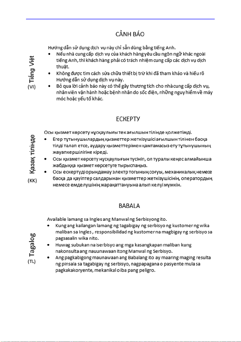
Translation policy
i-2 Vivid E80/E90/E95 – Service Manual
GC091052
Rev. 3
Page 5

Vivid E80/E90/E95 – Service Manual i-3
GC091052 Rev. 3
Page 6

i-4 Vivid E80/E90/E95 – Service Manual
GC091052
Rev. 3
Page 7

Vivid E80/E90/E95 – Service Manual i-5
GC091052 Rev. 3
Page 8

i-6 Vivid E80/E90/E95 – Service Manual
GC091052
Rev. 3
Page 9

Vivid E80/E90/E95 – Service Manual i-7
GC091052 Rev. 3
Page 10

i-8 Vivid E80/E90/E95 – Service Manual
GC091052
Rev. 3
Page 11

Vivid E80/E90/E95 – Service Manual i-9
GC091052 Rev. 3
Page 12

i-10 Vivid E80/E90/E95 – Service Manual
GC091052
Rev. 3
Page 13

Vivid E80/E90/E95 – Service Manual i-11
GC091052 Rev. 3
Page 14

i-12 Vivid E80/E90/E95 – Service Manual
GC091052
Rev. 3
Page 15

Vivid E80/E90/E95 – Service Manual i-13
GC091052 Rev. 3
Page 16
i-14 Vivid E80/E90/E95 – Service Manual
GC091052
Rev. 3
Page 17

Damage in transportation
All packages should be closely examined at time of delivery. If
damage is apparent, write “Damage In Shipment” on ALL copies
of the freight or express bill BEFORE delivery is accepted or
“signed for” by a GE representative or hospital receiving agent.
Whether noted or concealed, damage MUST be reported to the
carrier immediately upon discovery, or in any event, within 14
days after receipt, and the contents and containers held for
inspection by the carrier. A transport ation company will not pay a
claim for damage if an inspection is not requested within this 14
day period.
Certified electrical contractor statement - For USA Only
All electrical installations that are preliminary to positioning of
the equipment at the site prepared for the equipment shall be
performed by licensed electrical contractors. Other connections
between pieces of electrical equipment, calibrations, and testing
shall be performed by qualified GE personnel. In per for m ing all
electrical work on these products, GE will use its own specially
trained field engineers. All of GE’s electrical work on these
products will comply with the requirements of the applicable
electrical codes.
The purchaser of GE equipment shall only utilize qualified
personnel (i.e. GE field engineers, personnel of third-party
service companies with equivalent training, or licensed
electricians) to perform electrical servicing on the equipment.
Vivid E80/E90/E95 – Service Manual i-15
GC091052 Rev. 3
Page 18

Omission and errors
If there are any omissions, errors or sugges t ion s for imp ro vin g
this documentation, contact the GE Global Documentation
Group with specific information listing the system typ e, m an ual
title, part number or direction number, revision number, page
number and suggestion details.
Mail the
information to:
GE Vingmed Ultrasound AS
Service Documentation
P.O.Box 141
NO-3191 HORTEN
NORWAY
GE employees should use TrackWise to report service
documentation issues.
These issues will then be in the internal problem reporting tool
and communicated to the writer.
i-16 Vivid E80/E90/E95 – Service Manual
GC091052
Rev. 3
Page 19

WARNING
Service Safety Considerations
DANGER DANGEROUS VOLTAGES, CAPABLE OF CAUSING DEATH,
ARE PRESENT IN THIS EQUIPMENT. USE EXTREME
CAUTION WHEN HANDLING, TESTING AND ADJUSTING.
Use all Personal Protection Equipment (PPE) such as gloves,
safety shoes, safety glasses, and kneeling pads, to reduce the
risk of injury.
For a complete review of all safety requirements, see: ‘Safety
considerations’ on page 1-8.
Vivid E80/E90/E95 – Service Manual i-17
GC091052 Rev. 3
Page 20

Legal notes
The contents of this publication may not be copied or duplicated
in any form, in whole or in part, without prior written permission
of GE.
GE makes no representations or warranties with respect to the
information herein. In addition, the information is subject to
change without notice. Every precaution has been taken in the
preparation of this document. Nevertheless, GE assumes no
responsibility for errors, omissions, or any damages, including
special or consequential, resulting from the use of this
information. GE will issue updates to this information
periodically, as needed. If there are any questions regarding the
information contained in this manual, please contact your
GE Representative.
i-18 Vivid E80/E90/E95 – Service Manual
GC091052
Rev. 3
Page 21

Trademarks
Copyrights
All products and their name brands are trademarks of their
respective holders.
© 2014-2015 by General Electric Company.
All R ights Reserved.
Vivid E80/E90/E95 – Service Manual i-19
GC091052 Rev. 3
Page 22

THIS P A GE WAS INTENTIONALLY LEFT BLANK
i-20 Vivid E80/E90/E95 – Service Manual
GC091052
Rev. 3
Page 23

Translation policy - - - - - - - - - - - - - - - - - - - - - - - - - - - - - - - - - - - - - - - - i-2
Damage in transportation - - - - - - - - - - - - - - - - - - - - - - - - - - - - - - - - - i-15
Certified electrical contractor statement - For USA Only - - - - - - - - - - - - i-15
Omission and errors - - - - - - - - - - - - - - - - - - - - - - - - - - - - - - - - - - - - - i-16
Service Safety Considerations - - - - - - - - - - - - - - - - - - - - - - - - - - - - - - i-17
Legal notes - - - - - - - - - - - - - - - - - - - - - - - - - - - - - - - - - - - - - - - - - - - i-18
Trademarks - - - - - - - - - - - - - - - - - - - - - - - - - - - - - - - - - - - - - - - - - - i-19
Copyrights - - - - - - - - - - - - - - - - - - - - - - - - - - - - - - - - - - - - - - - - - - - - i-19
Table of Contents
Chapter 1 — Introduction
Manual Overview
Introduction - - - - - - - - - - - - - - - - - - - - - - - - - - - - - - - - - - - - - - - - - - - 1-2
Vivid E80/E90/E95 models covered by this manual - - - - - - - - - - - - - - - 1-2
Product description - - - - - - - - - - - - - - - - - - - - - - - - - - - - - - - - - - - - - - 1-3
Important conventions
Conventions used in book - - - - - - - - - - - - - - - - - - - - - - - - - - - - - - - - - 1-4
Standard hazard icons - - - - - - - - - - - - - - - - - - - - - - - - - - - - - - - - - - - 1-6
Product icons - - - - - - - - - - - - - - - - - - - - - - - - - - - - - - - - - - - - - - - - - - 1-7
Safety considerations
Introduction - - - - - - - - - - - - - - - - - - - - - - - - - - - - - - - - - - - - - - - - - - - 1-8
Human Safety - - - - - - - - - - - - - - - - - - - - - - - - - - - - - - - - - - - - - - - - - 1-8
Mechanical safety- - - - - - - - - - - - - - - - - - - - - - - - - - - - - - - - - - - - - - 1-11
Electrical safety - - - - - - - - - - - - - - - - - - - - - - - - - - - - - - - - - - - - - - - 1-14
Dangerous procedure warnings
Lockout/Tagout (LOTO) requirements
Returning probes and repair parts
Electromagnetic compatibility (EMC)
What is EMC? - - - - - - - - - - - - - - - - - - - - - - - - - - - - - - - - - - - - - - - - 1-19
Compliance - - - - - - - - - - - - - - - - - - - - - - - - - - - - - - - - - - - - - - - - - - 1-19
Electrostatic discharge (ESD) prevention - - - - - - - - - - - - - - - - - - - - - 1-20
Customer assistance
Contact information- - - - - - - - - - - - - - - - - - - - - - - - - - - - - - - - - - - - - 1-21
Phone numbers for Customer Assistance - - - - - - - - - - - - - - - - - - - - - 1-22
System manufacturer - - - - - - - - - - - - - - - - - - - - - - - - - - - - - - - - - - - 1-23
Chapter 2 — Site Preparations
General Ultrasound system requirements
Ultrasound system environmental requirements- - - - - - - - - - - - - - - - - - 2-2
Electrical requirements - - - - - - - - - - - - - - - - - - - - - - - - - - - - - - - - - - - 2-4
EMI limitations - - - - - - - - - - - - - - - - - - - - - - - - - - - - - - - - - - - - - - - - - 2-7
Table of Contents
Vivid E80/E90/E95 – Service Manual i-21
GC091052 Rev. 3
Page 24

EMI prevention/abatement- - - - - - - - - - - - - - - - - - - - - - - - - - - - - - - - - 2-8
Probes environmental requirements - - - - - - - - - - - - - - - - - - - - - - - - - - 2-9
Facility needs
Purchaser responsibilities - - - - - - - - - - - - - - - - - - - - - - - - - - - - - - - - 2-10
Required facility needs - - - - - - - - - - - - - - - - - - - - - - - - - - - - - - - - - - 2-12
Desirable features- - - - - - - - - - - - - - - - - - - - - - - - - - - - - - - - - - - - - - 2-13
Minimal floor plan suggestion- - - - - - - - - - - - - - - - - - - - - - - - - - - - - - 2-13
Recommended floor plan suggestion - - - - - - - - - - - - - - - - - - - - - - - - 2-14
Suggested floor plan, Ultrasound system, and EchoPAC PC in same room -
2-15
Networking setup requirements - - - - - - - - - - - - - - - - - - - - - - - - - - - - 2-15
Environmental Dangers
Patient Vicinity UL60601-1 (USA)- - - - - - - - - - - - - - - - - - - - - - - - - - - 2-18
Patient Environment IEC60601-1 (IEC60601-1-1) and ANSI AAMI
ES60601-1- - - - - - - - - - - - - - - - - - - - - - - - - - - - - - - - - - - - - - - - 2-19
Chapter 3 — System Setup
Setup reminders
Setup warnings- - - - - - - - - - - - - - - - - - - - - - - - - - - - - - - - - - - - - - - - - 3-2
Receiving and unpacking the equipment
Warnings for receiving and unpacking - - - - - - - - - - - - - - - - - - - - - - - - 3-4
The Tilt and Shock indicators- - - - - - - - - - - - - - - - - - - - - - - - - - - - - - - 3-5
Receiving the Vivid E80/E90/E95 - - - - - - - - - - - - - - - - - - - - - - - - - - - 3-8
Unpacking the Vivid E80/E90/E95 - - - - - - - - - - - - - - - - - - - - - - - - - - 3-11
Packing materials - recycling information
Preparing for setup
Verify customer order - - - - - - - - - - - - - - - - - - - - - - - - - - - - - - - - - - - 3-17
Physical inspection - - - - - - - - - - - - - - - - - - - - - - - - - - - - - - - - - - - - - 3-17
EMI protection - - - - - - - - - - - - - - - - - - - - - - - - - - - - - - - - - - - - - - - - 3-17
Completing the setup
System specifications - - - - - - - - - - - - - - - - - - - - - - - - - - - - - - - - - - - 3-18
Electrical specifications - - - - - - - - - - - - - - - - - - - - - - - - - - - - - - - - - - 3-19
Connections on the I/O Rear Panel - - - - - - - - - - - - - - - - - - - - - - - - - 3-20
Connections on the Patient I/O panel - - - - - - - - - - - - - - - - - - - - - - - - 3-21
Connecting probes - - - - - - - - - - - - - - - - - - - - - - - - - - - - - - - - - - - - - 3-22
Configuration
Vivid E80/E90/E95 configuration - - - - - - - - - - - - - - - - - - - - - - - - - - - 3-25
Service Screen setup - - - - - - - - - - - - - - - - - - - - - - - - - - - - - - - - - - - 3-32
Optional peripherals/peripheral connection - - - - - - - - - - - - - - - - - - - - 3-36
Software Options configuration - - - - - - - - - - - - - - - - - - - - - - - - - - - - 3-37
Connectivity overview
Physical connection - - - - - - - - - - - - - - - - - - - - - - - - - - - - - - - - - - - - 3-39
Connectivity setup
Compatibility - - - - - - - - - - - - - - - - - - - - - - - - - - - - - - - - - - - - - - - - - 3-41
Select TCP/IP Screen - - - - - - - - - - - - - - - - - - - - - - - - - - - - - - - - - - - 3-42
Changing the AE Title and/or Port Number (Port No.) - - - - - - - - - - - - 3-43
DHCP setup- - - - - - - - - - - - - - - - - - - - - - - - - - - - - - - - - - - - - - - - - - 3-44
Set the Remote Archive’s Network Information - - - - - - - - - - - - - - - - - 3-47
i-22 Vivid E80/E90/E95 – Service Manual
GC091052
Rev. 3
Page 25

Save the New Settings - - - - - - - - - - - - - - - - - - - - - - - - - - - - - - - - - - 3-49
Product Locator Installation Card
Chapter 4 — General Procedures and Functional Checks
General procedures
Power ON/Boot Up - - - - - - - - - - - - - - - - - - - - - - - - - - - - - - - - - - - - - - 4-2
Power shut down - - - - - - - - - - - - - - - - - - - - - - - - - - - - - - - - - - - - - - - 4-5
Complete power down - - - - - - - - - - - - - - - - - - - - - - - - - - - - - - - - - - - 4-7
Creating presets - - - - - - - - - - - - - - - - - - - - - - - - - - - - - - - - - - - - - - - - 4-8
Functional checks
2D Mode (B mode) checks - - - - - - - - - - - - - - - - - - - - - - - - - - - - - - - - 4-9
M Mode Checks - - - - - - - - - - - - - - - - - - - - - - - - - - - - - - - - - - - - - - - 4-13
Color Mode Checks - - - - - - - - - - - - - - - - - - - - - - - - - - - - - - - - - - - - 4-17
PW/CW Doppler Mode Checks - - - - - - - - - - - - - - - - - - - - - - - - - - - - 4-21
Tissue Velocity Imaging (TVI) Checks- - - - - - - - - - - - - - - - - - - - - - - - 4-25
Probe/Connectors Checks- - - - - - - - - - - - - - - - - - - - - - - - - - - - - - - - 4-29
ECG Check - - - - - - - - - - - - - - - - - - - - - - - - - - - - - - - - - - - - - - - - - - 4-30
Cineloop Check - - - - - - - - - - - - - - - - - - - - - - - - - - - - - - - - - - - - - - - 4-31
Back End Processor checks - - - - - - - - - - - - - - - - - - - - - - - - - - - - - - 4-32
Operating Panel Test - - - - - - - - - - - - - - - - - - - - - - - - - - - - - - - - - - - 4-33
Peripheral checks - - - - - - - - - - - - - - - - - - - - - - - - - - - - - - - - - - - - - - 4-33
Mechanical Functions Checks - - - - - - - - - - - - - - - - - - - - - - - - - - - - - 4-35
Chapter 5 — Components and Functions (Theory)
Software overview
System software- - - - - - - - - - - - - - - - - - - - - - - - - - - - - - - - - - - - - - - - 5-2
Application software - - - - - - - - - - - - - - - - - - - - - - - - - - - - - - - - - - - - - 5-2
InSite ExC
Introduction - - - - - - - - - - - - - - - - - - - - - - - - - - - - - - - - - - - - - - - - - - - 5-3
InSite ExC Icon- - - - - - - - - - - - - - - - - - - - - - - - - - - - - - - - - - - - - - - - - 5-3
InSite ExC Status - - - - - - - - - - - - - - - - - - - - - - - - - - - - - - - - - - - - - - - 5-4
InSite ExC Definitions - - - - - - - - - - - - - - - - - - - - - - - - - - - - - - - - - - - - 5-5
Initiating a Request for Service (RFS)- - - - - - - - - - - - - - - - - - - - - - - - - 5-6
Exiting InSite ExC- - - - - - - - - - - - - - - - - - - - - - - - - - - - - - - - - - - - - - - 5-9
Vivid E80/E90/E95 overview
Introduction - - - - - - - - - - - - - - - - - - - - - - - - - - - - - - - - - - - - - - - - - - 5-10
Note regarding USB ports - - - - - - - - - - - - - - - - - - - - - - - - - - - - - - - - 5-10
Related information- - - - - - - - - - - - - - - - - - - - - - - - - - - - - - - - - - - - - 5-10
Vivid E80/E90/E95 block diagram- - - - - - - - - - - - - - - - - - - - - - - - - - - 5-11
Signal flow overview - - - - - - - - - - - - - - - - - - - - - - - - - - - - - - - - - - - - 5-12
System configuration and software- - - - - - - - - - - - - - - - - - - - - - - - - - 5-12
Operating Panel - - - - - - - - - - - - - - - - - - - - - - - - - - - - - - - - - - - - - - - 5-12
The electronics- - - - - - - - - - - - - - - - - - - - - - - - - - - - - - - - - - - - - - - - 5-12
Operating modes - - - - - - - - - - - - - - - - - - - - - - - - - - - - - - - - - - - - - - 5-13
Top Console with LCD monitor and Operating Panel
Top Console description - - - - - - - - - - - - - - - - - - - - - - - - - - - - - - - - - 5-14
Operating Panel (Control Panel)- - - - - - - - - - - - - - - - - - - - - - - - - - - - 5-19
Main Console
Main Console description - - - - - - - - - - - - - - - - - - - - - - - - - - - - - - - - 5-21
Vivid E80/E90/E95 – Service Manual i-23
GC091052 Rev. 3
Page 26

Air Flow control
Air Flow components- - - - - - - - - - - - - - - - - - - - - - - - - - - - - - - - - - - - 5-22
Software control - - - - - - - - - - - - - - - - - - - - - - - - - - - - - - - - - - - - - - - 5-22
Location- - - - - - - - - - - - - - - - - - - - - - - - - - - - - - - - - - - - - - - - - - - - - 5-23
Casters and brakes
Casters and brakes description - - - - - - - - - - - - - - - - - - - - - - - - - - - - 5-24
Front End Processor (FEP)
Front End Card Rack general description - - - - - - - - - - - - - - - - - - - - - 5-25
Transmitter board (GTX) - - - - - - - - - - - - - - - - - - - - - - - - - - - - - - - - - 5-26
Relay board (GRLY) - - - - - - - - - - - - - - - - - - - - - - - - - - - - - - - - - - - - 5-28
CRX board- - - - - - - - - - - - - - - - - - - - - - - - - - - - - - - - - - - - - - - - - - - 5-30
Front Plane boards (XD BUS) - - - - - - - - - - - - - - - - - - - - - - - - - - - - - 5-32
cSound Power Module (CPM) - - - - - - - - - - - - - - - - - - - - - - - - - - - - - 5-33
Back End Processor (BEP)
Introduction - - - - - - - - - - - - - - - - - - - - - - - - - - - - - - - - - - - - - - - - - - 5-34
Signal flow and processing - - - - - - - - - - - - - - - - - - - - - - - - - - - - - - - 5-34
Location of the Back End Processor (BEP) - - - - - - - - - - - - - - - - - - - - 5-34
BEP description - - - - - - - - - - - - - - - - - - - - - - - - - - - - - - - - - - - - - - - 5-34
BEP’s side connectors - - - - - - - - - - - - - - - - - - - - - - - - - - - - - - - - - - 5-35
BEP’s top connectors - - - - - - - - - - - - - - - - - - - - - - - - - - - - - - - - - - - 5-36
BEP’s rear connectors- - - - - - - - - - - - - - - - - - - - - - - - - - - - - - - - - - - 5-36
Inside the BEP - - - - - - - - - - - - - - - - - - - - - - - - - - - - - - - - - - - - - - - - 5-36
LEDs- - - - - - - - - - - - - - - - - - - - - - - - - - - - - - - - - - - - - - - - - - - - - - - 5-37
BEP Power Supply - - - - - - - - - - - - - - - - - - - - - - - - - - - - - - - - - - - - - 5-38
Graphics adapters - - - - - - - - - - - - - - - - - - - - - - - - - - - - - - - - - - - - - 5-38
Internal storage devices - - - - - - - - - - - - - - - - - - - - - - - - - - - - - - - - - 5-38
Power distribution
Main Power Supply- - - - - - - - - - - - - - - - - - - - - - - - - - - - - - - - - - - - - 5-39
cSound Power Module (CPM) - - - - - - - - - - - - - - - - - - - - - - - - - - - - - 5-42
Input and Output (I/O) modules
Patient I/O (Physio)- - - - - - - - - - - - - - - - - - - - - - - - - - - - - - - - - - - - - 5-43
BEP I/O Board - - - - - - - - - - - - - - - - - - - - - - - - - - - - - - - - - - - - - - - - 5-45
Restart Vivid E80/E90/E95 after diagnostics
Chapter 6 — Service Adjustments
LCD Monitor adjustments
Cautions and Warnings - - - - - - - - - - - - - - - - - - - - - - - - - - - - - - - - - - - 6-2
LCD backlight adjustment - - - - - - - - - - - - - - - - - - - - - - - - - - - - - - - - - 6-3
Chapter 7 — Diagnostics/Troubleshooting
Service safety considerations
Gathering Troubleshooting Data
Purpose of this section - - - - - - - - - - - - - - - - - - - - - - - - - - - - - - - - - - - 7-3
Collect Vital System Information- - - - - - - - - - - - - - - - - - - - - - - - - - - - - 7-3
Collect a ‘trouble image’ with logs- - - - - - - - - - - - - - - - - - - - - - - - - - - - 7-4
Screen captures
Purpose of this section - - - - - - - - - - - - - - - - - - - - - - - - - - - - - - - - - - - 7-6
Ctrl+PrintScreen shortcut - - - - - - - - - - - - - - - - - - - - - - - - - - - - - - - - - 7-6
Capture a screen image using the shortcut - - - - - - - - - - - - - - - - - - - - - 7-7
i-24 Vivid E80/E90/E95 – Service Manual
GC091052
Rev. 3
Page 27

Troubleshooting
XY Lock is not working - - - - - - - - - - - - - - - - - - - - - - - - - - - - - - - - - - - 7-8
Related information: - - - - - - - - - - - - - - - - - - - - - - - - - - - - - - - - - - - - - 7-8
XY Brake Motors Troubleshooting - - - - - - - - - - - - - - - - - - - - - - - - - - - 7-8
Z Movement fails - - - - - - - - - - - - - - - - - - - - - - - - - - - - - - - - - - - - - - - 7-8
Motor controller test - - - - - - - - - - - - - - - - - - - - - - - - - - - - - - - - - - - - 7-10
Chapter 8 — Replacement Procedures
Warnings and important information
Warnings - - - - - - - - - - - - - - - - - - - - - - - - - - - - - - - - - - - - - - - - - - - - - 8-2
Returning/shipping probes and repair parts - - - - - - - - - - - - - - - - - - - - - 8-3
Manpower - When two persons are needed - - - - - - - - - - - - - - - - - - - - 8-5
Tools needed for servicing Vivid E80/E90/E95- - - - - - - - - - - - - - - - - - - 8-5
Loading the software
Loading the software from Usb Flash Drive (UFD) - - - - - - - - - - - - - - - - 8-7
Setup after software loading - - - - - - - - - - - - - - - - - - - - - - - - - - - - - - - 8-8
Replacing covers and bumpers
Side covers replacement - - - - - - - - - - - - - - - - - - - - - - - - - - - - - - - - - - 8-9
Top Cover replacement- - - - - - - - - - - - - - - - - - - - - - - - - - - - - - - - - - 8-11
Foot rest bumper replacement - - - - - - - - - - - - - - - - - - - - - - - - - - - - - 8-14
Front cover replacement - - - - - - - - - - - - - - - - - - - - - - - - - - - - - - - - - 8-16
Plate connectors
Filter cover and filter replacement- - - - - - - - - - - - - - - - - - - - - - - - - - - 8-21
Rear cover replacement - - - - - - - - - - - - - - - - - - - - - - - - - - - - - - - - - 8-23
Rear bumper replacement- - - - - - - - - - - - - - - - - - - - - - - - - - - - - - - - 8-25
Rear handle replacement - - - - - - - - - - - - - - - - - - - - - - - - - - - - - - - - 8-27
LCD Monitor and LCD Arm parts replacement
Replacing the 19” LCD Monitor assembly - - - - - - - - - - - - - - - - - - - - - 8-29
Replacing the LCD Arm assembly - - - - - - - - - - - - - - - - - - - - - - - - - - 8-31
LCD Z-Lock replacement- - - - - - - - - - - - - - - - - - - - - - - - - - - - - - - - - 8-33
Upper OP Panel/Touch Panel Assembly replacement
Read and follow - - - - - - - - - - - - - - - - - - - - - - - - - - - - - - - - - - - - - - - 8-35
Preparations- - - - - - - - - - - - - - - - - - - - - - - - - - - - - - - - - - - - - - - - - - 8-35
Remove the Upper OP Panel/Touch Panel Assembly - - - - - - - - - - - - 8-36
Install the Upper OP Panel/Touch Panel Assembly - - - - - - - - - - - - - - 8-36
Verification- - - - - - - - - - - - - - - - - - - - - - - - - - - - - - - - - - - - - - - - - - - 8-37
Lower Operating Panel Parts replacement
Knobs for Encoders and Slidepots replacement- - - - - - - - - - - - - - - - - 8-38
Replacing the Operating Panel, Lower - - - - - - - - - - - - - - - - - - - - - - - 8-39
Replacing the Trackball- - - - - - - - - - - - - - - - - - - - - - - - - - - - - - - - - - 8-42
A/N Keyboard parts replacement
Replacing the Alpha-Numeric (A/N) Keyboard Assembly - - - - - - - - - - 8-45
Wagon AN Drawer Sheet Met. Assembly replacement- - - - - - - - - - - - 8-48
Other Top Console Parts replacement
Replacing the Speaker Assembly- - - - - - - - - - - - - - - - - - - - - - - - - - - 8-51
Replacing the Bulkhead Board- - - - - - - - - - - - - - - - - - - - - - - - - - - - - 8-53
Bulkhead, Plate, Extended replacement - - - - - - - - - - - - - - - - - - - - - - 8-54
Handle, Left Top / Handle Right Top, replacement- - - - - - - - - - - - - - - 8-56
w
/guide replacement - - - - - - - - - - - - - - - - - - - - - - - 8-19
Vivid E80/E90/E95 – Service Manual i-25
GC091052 Rev. 3
Page 28

Palm Rest ASSY replacement - - - - - - - - - - - - - - - - - - - - - - - - - - - - - 8-58
Up-Down Button Board (Buttons Frame UI Assy) replacement - - - - - - 8-59
Button IF Board Assy replacement - - - - - - - - - - - - - - - - - - - - - - - - - - 8-61
Replacing XYZ Parts
XY Mechanism replacement - - - - - - - - - - - - - - - - - - - - - - - - - - - - - - 8-63
Z-Mechanism replacement - - - - - - - - - - - - - - - - - - - - - - - - - - - - - - - 8-65
XYZ Control Assembly replacement - - - - - - - - - - - - - - - - - - - - - - - - - 8-67
Main Console parts replacement
Fan Assembly replacement - - - - - - - - - - - - - - - - - - - - - - - - - - - - - - - 8-69
Main Cable replacement - - - - - - - - - - - - - - - - - - - - - - - - - - - - - - - - - 8-70
Casters and Brakes replacement
Rear Casters replacement- - - - - - - - - - - - - - - - - - - - - - - - - - - - - - - - 8-73
Front Casters replacement - - - - - - - - - - - - - - - - - - - - - - - - - - - - - - - 8-76
Pedal Mechanism replacement - - - - - - - - - - - - - - - - - - - - - - - - - - - - 8-79
Brake Pedal replacement - - - - - - - - - - - - - - - - - - - - - - - - - - - - - - - - 8-83
Pedal Release replacement- - - - - - - - - - - - - - - - - - - - - - - - - - - - - - - 8-83
Pedal Dir Lock replacement- - - - - - - - - - - - - - - - - - - - - - - - - - - - - - - 8-84
Front End Processor (FEP) / Card Cage parts replacement
Front End parts overview- - - - - - - - - - - - - - - - - - - - - - - - - - - - - - - - - 8-85
Front End cover replacement- - - - - - - - - - - - - - - - - - - - - - - - - - - - - - 8-86
Relay Board (RLY) replacement- - - - - - - - - - - - - - - - - - - - - - - - - - - - 8-88
Transmitter Board (GTX) replacement - - - - - - - - - - - - - - - - - - - - - - - 8-91
cSound Receiver Board (CRX) replacement - - - - - - - - - - - - - - - - - - - 8-93
cSound Power Module (CPM) replacement- - - - - - - - - - - - - - - - - - - - 8-95
Back End Processor (BEP) parts replacement
Back End Processor (BEP) replacement- - - - - - - - - - - - - - - - - - - - - - 8-97
Hard Disk Drive (HDD) replacement- - - - - - - - - - - - - - - - - - - - - - - - 8-101
Main Power Supply replacement
Preparations- - - - - - - - - - - - - - - - - - - - - - - - - - - - - - - - - - - - - - - - - 8-105
Main Power Supply removal procedure- - - - - - - - - - - - - - - - - - - - - - 8-105
Main Power Supply installation procedure- - - - - - - - - - - - - - - - - - - - 8-105
Patient I/O assembly replacement
Read and follow - - - - - - - - - - - - - - - - - - - - - - - - - - - - - - - - - - - - - - 8-107
Preparations- - - - - - - - - - - - - - - - - - - - - - - - - - - - - - - - - - - - - - - - - 8-107
Patient I/O module removal procedure - - - - - - - - - - - - - - - - - - - - - - 8-107
Patient I/O installation procedure - - - - - - - - - - - - - - - - - - - - - - - - - - 8-108
Verification- - - - - - - - - - - - - - - - - - - - - - - - - - - - - - - - - - - - - - - - - - 8-108
Peripherals replacement
DVD R/W drive replacement - - - - - - - - - - - - - - - - - - - - - - - - - - - - - 8-109
Black & White Digital Graphic Printer replacement- - - - - - - - - - - - - - 8-110
Cables replacement
TwinAx PCIe cable replacement- - - - - - - - - - - - - - - - - - - - - - - - - - - 8-112
i-26 Vivid E80/E90/E95 – Service Manual
GC091052
Rev. 3
Page 29

Chapter 9 — Renewal Parts
List of Abbreviations
Software for Vivid E80/E90/E95
Covers and Bumpers
Top Console parts
Main Monitor and LCD Arm parts - - - - - - - - - - - - - - - - - - - - - - - - - - - - 9-9
Operating Panel (OP) parts - - - - - - - - - - - - - - - - - - - - - - - - - - - - - - - 9-11
Alphanumeric (AN) Keyboard parts - - - - - - - - - - - - - - - - - - - - - - - - - 9-12
Speaker and Bulkhead parts - - - - - - - - - - - - - - - - - - - - - - - - - - - - - - 9-13
XYZ parts
Main Console parts
Casters (wheels) parts
Front End Processor (FEP) Card Rack parts
Back End Processor (BEP) parts
Main Power Supply
I/O modules parts
Peripherals for use with Vivid E80/E90/E95
DVD drive - - - - - - - - - - - - - - - - - - - - - - - - - - - - - - - - - - - - - - - - - - - 9-21
Internal printer - - - - - - - - - - - - - - - - - - - - - - - - - - - - - - - - - - - - - - - - 9-21
External printers - - - - - - - - - - - - - - - - - - - - - - - - - - - - - - - - - - - - - - - 9-22
Digital Video Stream Recorder (external) - - - - - - - - - - - - - - - - - - - - - 9-22
3D Monitor - external- - - - - - - - - - - - - - - - - - - - - - - - - - - - - - - - - - - - 9-23
Mains power cables - Vivid E80/E90/E95
Internal Cables - Vivid E80/E90/E95
ECG cables - Vivid E80/E90/E95
Physio TX parts
Probes for Vivid E80/E90/E95
Phased Array Sector probes - - - - - - - - - - - - - - - - - - - - - - - - - - - - - - 9-31
Linear Array probes - - - - - - - - - - - - - - - - - - - - - - - - - - - - - - - - - - - - 9-31
Curved Array (Convex) probes- - - - - - - - - - - - - - - - - - - - - - - - - - - - - 9-32
Doppler probes- - - - - - - - - - - - - - - - - - - - - - - - - - - - - - - - - - - - - - - - 9-32
Transesophageal Phased Array probes - - - - - - - - - - - - - - - - - - - - - - 9-33
Intra-operative probes - - - - - - - - - - - - - - - - - - - - - - - - - - - - - - - - - - - 9-33
Options - Vivid E80/E90/E95
Chapter 10 — Care and Maintenance
Overview
Periodic maintenance inspections - - - - - - - - - - - - - - - - - - - - - - - - - - 10-2
Why do maintenance
Quality assurance- - - - - - - - - - - - - - - - - - - - - - - - - - - - - - - - - - - - - - 10-3
Maintenance task schedule
How often should maintenance tasks be performed? - - - - - - - - - - - - - 10-4
Index
Vivid E80/E90/E95 – Service Manual i-27
GC091052 Rev. 3
Page 30

i-28 Vivid E80/E90/E95 – Service Manual
GC091052
Rev. 3
Page 31

Chapter 1
Introduction
This chapter describes important issues related to
safely servicing the Vivid E80/E90/E95. The service
provider must read and understand all the information
presented here before installing or servicing the Vivid
E80/E90/E95.
Vivid E80/E90/E95 – Service Manual 1-1
GC091052 Rev. 3
Page 32

Introduction
Manual Overview
Introduction
This manual provides installation and service info rmation for the
Vivid E80/E90/E95.
Vivid E80/E90/E95 models covered by this manual
Table 1-1: Vivid E80/E90/E95 models and software compatibility
Model
Number
GC000220 Vivid E95 v200.0 v201.0 v201.x
GC000230 Vivid E90 v200.0 v201.0 v201.x
GC000240 Vivid E80 v200.0 v201.0 v201.x
Description System SWAppl.
SW
NOTE: Unless otherwise specified, the content of this manual applies to
all Vivid E80/E90/E95 models.
Can be
upgraded
to
1-2 Vivid E80/E90/E95 – Service Manual
GC091052
Rev. 3
Page 33

Manual Overview
Product description
Overview of the Vivid E80/E90/E95 Ultrasound system
This Vivid E80/E90/E95 is a high performance digit al ultras ound
imaging system with total data management.
The Ultrasound system provides image generation in 2D, Color
Doppler, Power Doppler, M-Mode, Color M-Mode, PW and 4D,
Tissue Velocity imaging, and Contrast applications.
The fully digital architecture of the Vivid E80/E90/E95 allows
optimal usage of all scanning modes and probe types
throughout the full spectrum of operating frequencies.
Signal flows from the Probe Connector Panel to the Front End,
and then over to the Back End Processor and finally to the
monitor and peripherals.
System configuration is stored on the Vivid E80/E90/E95.
All necessary software is loaded from the hard drive on power
up.
Purpose of the operator manual(s)
The operator manuals should be fully read and understood
before operating the Vivid E80/E90/E95.
The online versions of the operator manuals are available via
the Help function on Vivid E80/E90/E95’s Operating Panel.
The translated user manuals are available as PDF files on the
Usb Flash Drive (UFD) delivered with the Vivid E80/E90/E95.
Vivid E80/E90/E95 – Service Manual 1-3
GC091052 Rev. 3
Page 34

Introduction
DANGER
Important conventions
Conventions used in book
Important conventions, used in this document, are described
below.
Model designations
This manual covers the Ultrasound systems listed in:
‘Vivid E80/E90/E95 models covered by this ma nual’ on
page 1-2.
Icons
Pictures, or icons, are used wherever they will reinforce the
printed message. The icons, labels, and conventions used on
the product and in the service information are de scr ib ed in this
chapter.
Safety precaution messages
Various levels of safety precaution me ss ag e s ma y be fo und on
the equipment and in the service informatio n . The different
levels of concern are identified by a flag word that precedes the
precautionary message. Known or potential hazards to
personnel are labeled in one of three ways:
• DANGER
• WARNING
• CAUTION
Danger is used to indicate the presence of a hazard that will
cause severe personal injury or death, or substantial property
damage if the instructions are ignored.
1-4 Vivid E80/E90/E95 – Service Manual
GC091052
Rev. 3
Page 35

Important conventions
WARNING
CAUTION
Warning is used to indicate the presence of a hazard that may
cause severe personal injury or substantial property damage if
instructions are ignored.
Caution is used to indicate the presence of a hazard that will or
can cause minor personal injury or property damage if
instructions are ignored.
NOTE: Notes are used to provide important information about an item
or a procedure.
NOTE: Be sure to read the notes; the information contained in a note
can often save you time or effort.
Vivid E80/E90/E95 – Service Manual 1-5
GC091052 Rev. 3
Page 36

Introduction
Standard hazard icons
Important information will always be preceded by either the
exclamation point (!) contained within a triangle, or the symbols
for “Danger”, “Warning” or “Caution” , as seen throughout this
chapter. In addition to text, several different graphical icons
(symbols) may be used to make you aware of specific types of
hazards that could possibly cause harm. Even if a symbol isn’t
used in this manual, it may be included for your reference.
Table 1-2: Standard hazard icons
ELECTRICAL
MECHANICAL
RADIATION
LASER
HEAT
PINCH
NOTE: Even if a symbol isn’t used on the product or in this manual, it
may be included for your reference.
1-6 Vivid E80/E90/E95 – Service Manual
GC091052
Rev. 3
Page 37

Important conventions
Standard Icons that indicate that a special procedure is to be used
Some others icons make you aware of specific procedures that
should be followed.
Table 1-3: Standard Icons that indicates that a special procedure is to be used
Avoid Static Electricity Tag and Lock Out Wear Eye Protection
Hand Protection Foot Protection Wear Eye Protection
Product icons
Refer to the Device labels in the Safety chapter in the User
Manual.
Vivid E80/E90/E95 – Service Manual 1-7
GC091052 Rev. 3
Page 38

Introduction
WARNING
WARNING
Safety considerations
Introduction
The following safety precautions must be observed during all
phases of operation, service and repair of this equipment.
Failure to comply with these precautions or with specific
warnings elsewhere in this manual violates safety standards of
design, manufacture, and intended use of the equipment.
Human Safety
• Operating personnel must not remove the Ultrasound
system covers.
• Servicing should be performed by authorized personnel
only .
Only personnel who have participated in a Vivid E80/E90/
E95 Training Seminar are authorized to service the
equipment.
NOTE: Local laws may restrict this device for sale or use by or on the
order of a physician.
NOTE: For Vivid E80/E90/E95 Vet, local laws may restrict this device
for sale or use by or on the order of a veterinarian.
DANGER DANGEROUS VOLTAGES, CAPABLE OF CAUSING DEATH,
ARE PRESENT IN THIS EQUIPMENT. USE EXTREME
CAUTION WHEN HANDLING, TESTING AND ADJUSTING.
If the covers are removed from an operating Vivid E80/E90/
E95, some metal surfaces may be warm enough to pose a
potential heat hazard if touched, even while in shutdown mode.
Because of the limited access to cabinets and equipment in the
field, placing people in awkward positions, GE has limited the
lifting weight for one person in the field to 16 KG (35 LBS).
Anything over 16 KG (35 LBS) requires 2 people.
1-8 Vivid E80/E90/E95 – Service Manual
GC091052
Rev. 3
Page 39

Safety considerations
WARNING
WARNING
WARNING
WARNING
WARNING
Have two people available to deliver and unpack the Vivid E80/
E90/E95.
Attempts to move the Vivid E80/E90/E95 considerable
distances or on an incline by one person could result in injury
or damage or both.
Explosion Warning
DO NOT operate the equipment in an explosive atmosphere.
Operation of any electrical equipment in such an environment
constitutes a definite safety hazard.
DO NOT substitute parts or modify equipment
Because of the danger of introducing additional hazards, ONLY
install GE approved part s. DO NOT perform any unauthorized
modification of the equipment.
Tilting the console requires two people in order to avoid injury
to service personnel and damage to the equipment.
Ensure that the Ultrasound system is turned off and unplugged
Wait for at least 20 seconds for capacitors to discharge as
there are no test points to verify isolation. The amber light on
the OP panel ON/OFF button will turn off.
Ultrasound system components may be energized. Always
refer to the Ultrasound system's Proprietary Ser vice Manual for
LOTO warnings and cautions
Vivid E80/E90/E95 – Service Manual 1-9
GC091052 Rev. 3
Page 40

Introduction
WARNING
WARNING
WARNING
WARNING
WARNING
WARNING
When the top console is in its locked position, the gas shock is
compressed and stores mechanical energy. During normal
operation the top console, the weight of the monitor and the
mechanical force of the gas shock are in balance. Take care if/
when you activate this gas shock. Personal injury can occur
after the panel is removed and the shock pressure is released.
Take care when you repair the e levation assembly.
Risk of electrical shock, Ultrasound system must be turned off
and disconnected from power source. Cord must be controlled
at all times.
Wait for at least 20 seconds for capacitors to discharge as
there are no test points to verify isolation. The amber light on
the OP panel on/off button will turn off.
Ultrasound System components may be energized. Always
refer to the Ultrasound system's Proprietary Ser vice Manual for
LOTO warnings and cautions.
Explosion Warning
DO NOT operate the equipment in an explosive atmosphere.
Operation of any electrical equipment in such an environment
constitutes a definite safety hazard.
Use all Personal Protection Equipment (PPE) such as gloves,
safety shoes, safety glasses, and kneeling pads, to reduce the
risk of injury.
Beware of possible sharp edges on all mechanical parts. If
sharp edges are encountered, the appropriate PPE should be
used to reduce the risk of injury.
Wear all PPE including gloves as indicated in the chemical
MSDS.
1-10 Vivid E80/E90/E95 – Service Manual
GC091052
Rev. 3
Page 41

Safety considerations
WARNING
WARNING
WARNING
WARNING
WARNING
WARNING
WARNING
Mechanical safety
While the software install procedure is designed to preserve
data, you should save any patien t data, images, system setup s
to removable media or hardcopy before doing a software
upgrade.
Ultrasound probes are highly sensitive medical instruments
that can easily be damaged by improper handling. Use care
when handling and protect from damage when not in use. Do
not use a damaged or defective probe. Failure to follow these
precautions can result in serious injury and equipment
damage.
Never use a probe that has fallen to the floor. Even if it looks
OK, it may be damaged.
The Ultrasound system should not be moved with the Operator
I/O Panel extended. Move the operator i/o panel to its ce ntered
and locked position. Lower the Operator I/O Panel as much as
possible before moving the Ultrasound system.
Prior to elevating Ultrasound system:
• verify that the floating Operating Panel is locked in its
lowest, parking position.
• verify that the front brake is locked and the Ultrasound
system is unable to swivel.
• verify that the rear brakes are in the locked position.
When the Ultrasound system is raised for a repair or moved
along any incline, use extreme caution since it may become
unstable and tip over.
Remember: If the front caster swivel lock is engaged for
transportation, pressing the release pedal once disengages the
swivel lock. You must depress the release pedal a second time
to engage the brake.
Vivid E80/E90/E95 – Service Manual 1-11
GC091052 Rev. 3
Page 42

Introduction
CAUTION
CAUTION
CAUTION
CAUTION
CAUTION
CAUTION
CAUTION
Before you move or transport the Ultrasound system, make
sure to lock the LCD monitor arm firmly and flip down the
monitor to prevent damage to the Ultrasound system.
Always lock the Top Console (Operating Panel) in its parking
(locked) position before moving the Ultrasound system around.
Do not move the Ultrasound system if the Operating Panel is in
unlocked position.
To avoid injury when you move the LCD monitor and the
monitor arm, do not put your finger, hand, or object on the joint
of the monitor or the monitor arm.
Ensure that nobody touches the console arm/frogleg when
moving the Operating Panel.
Keep the heat venting holes on the monitor unobstructed to
avoid overheating of the monitor.
Vivid E80/E90/E95 weighs 128 kg (283 lb.) or more, depending
on installed peripherals, when ready for use. Care must be
used when moving it or replacing its parts.
Failure to follow the precautions listed below could result in
injury, uncontrolled motion and costly damage.
ALWAYS:
• be sure the pathway is clear
• use slow, careful motions
• use two people when moving on inclines or lifting more
than 16 kg (35 lbs)
1-12 Vivid E80/E90/E95 – Service Manual
GC091052
Rev. 3
Page 43

Safety considerations
CAUTION
CAUTION
CAUTION
CAUTION
CAUTION
Do not transport Vivid E80/E90/E95 in a vehicle without locking
the casters (wheels) and securing it as described in chapter 4.
Use protective glasses during drilling, filing smooth
surfaces, and during all other work where ey es ne e d
protection.
Use protective gloves when working with sharp edges
or when directed to wear PPE during a removal/
replacement procedure.
Use safety shoes when doing work where there is any
chance of foot injury.
Be careful not to pinch any of the cables.
NOTE: Special care should be taken when transporting the Ultrasound
system in a vehicle:
• Before transporting, place the Ultrasound system in its
special storage case.
• Ensure that the Ultrasound system is firmly secured while
inside the vehicle.
• Secure Ultrasound system with straps or as directed
otherwise to prevent motion during transport.
• Prevent vibration damage by driving cautiously. Avoid
unpaved roads, excessive speeds, and erratic stops or
starts.
Vivid E80/E90/E95 – Service Manual 1-13
GC091052 Rev. 3
Page 44

Introduction
WARNING
Electrical safety
Safe practices
Follow these guidelines to minimize shock hazards whenever
you are using the Vivid E80/E90/E95:
• To minimize shock hazard, the equipment chassis must be
connected to an electrical ground.
• The Vivid E80/E90/E95 is equipped with a three-conductor
AC power cable. This must be plugged into an approved
electrical outlet with safety ground.
• The power outlet used for this equipment should not be
shared with other types of equipment.
• Both the Vivid E80/E90/E95 power cable and the power
connector must meet international electrical standards
Connecting a Vivid E80/E90/E95 to the wrong voltage level will
most likely destroy it.
1-14 Vivid E80/E90/E95 – Service Manual
GC091052
Rev. 3
Page 45

Safety considerations
Probes
Follow these guidelines before connecting a probe to the
Ultrasound system:
• Inspect the probe prior to each use for damage or
degradation to the:
• housing
• cable strain relief
• lens
• seal
• connector pins
• locking mechanism
• Do not use a damaged or defective probe.
• Never immerse the probe connector or adapter into any
liquid.
• The Vivid E80/E90/E95 has more than one type of probe
port. Use the appropriate probe port designed for the probe
you are connecting.
Peripherals
Refer to the Patient Safety Environment section of the User’s
Manual for peripheral isolation information.
Vivid E80/E90/E95 – Service Manual 1-15
GC091052 Rev. 3
Page 46

Introduction
DANGER
WARNING
WARNING
WARNING
Dangerous procedure warnings
Warnings, such as the example below, precede potentially
dangerous procedures throughout this manual. Instructions
contained in the warnings must be followed.
DANGEROUS VOL T AGES, CAPABLE OF CAUSING
DEA TH, ARE PRESENT IN THIS EQUIPMENT. USE
EXTREME CAUTION WHEN HANDLING, TESTING
AND ADJUSTING.
If the covers are removed from an operating Vivid E80/E90/
E95, some metal surfaces may be warm enough to pose a
potential heat hazard if touched, even while in shutdown mode.
Explosion Warning
DO NOT operate the equipment in an explosive atmosphere.
Operation of any electrical equipment in such an environment
constitutes a definite safety hazard.
DO NOT substitute parts or modify equipment
Because of the danger of introducing additional hazards, ONLY
install GE approved part s. DO NOT perform any unauthorized
modification of the equipment.
1-16 Vivid E80/E90/E95 – Service Manual
GC091052
Rev. 3
Page 47

Lockout/Tagout (LOTO) requirements
WARNING
Lockout/Tagout (LOTO)
requirements
Follow Lockout/T agout requirements by ensuring you are in total
control of the AC power plug at all times during the service
process.
To apply Lockout/Tagout (LOTO):
1. Plan and prepare for shutdown.
2. Shutdown the equipment.
3. Isolate the equipment.
4. Apply Lockout/Tagout Devices.
5. Control all stored and residual energy.
6. Verify isolation.
All potentially hazardous stored or residual energy is relieved.
Energy Control and Power Lockout for Vivid E80/E90/E95.
When servicing parts of the Ultrasound system where there is
exposure to voltage greater than 30 volts:
1. Follow LOCK OUT/TAG OUT procedures.
2. Turn off the breaker.
3. Unplug the Ultrasound system.
4. Maintain control of the Ultrasound system power plug.
5. Wait at least 30 seconds for capacitors to discharge as
there are no test points to verify isolation.
Ultrasound System components may be energized.
Vivid E80/E90/E95 – Service Manual 1-17
GC091052 Rev. 3
Page 48

Introduction
Returning probes and repair parts
Equipment being returned must be clean and free of blood and other infectious
substances. GE policy states that body fluids must be prop er ly re moved from a ny part
or equipment prior to shipment. GE employees, as well as customers, are responsible
for ensuring that parts/equipment have been properly decontaminated prior to
shipment. Under no circumstance should a part or equipment with visible body fluids
be taken or shipped from a clinic or site (for example, body coils or an ultrasou nd
probe).
The purpose of the regulation is to protect employees in the transporta tion industry, as
well as the people who will receive or open this package.
NOTE: The US Depar tment of Transportation (DOT) has ruled that
“items that were saturated and/or dripping with human blood
that are now caked with dried blood; or which were used or
intended for use in patient care” are “regulated medical waste”
for transportation purposes and must be transported as a
hazardous material.
NOTE: The USER/SERVICE staff should dispose of all the waste
properly , per federal, st ate, and local waste disposal regulation s.
The Vivid E80/E90/E95 is not meant to be used for long-term storage of patient data
or images. The user is responsible for the data on the Vivid E80/E90/E95 and a
regular backup is highly recommended.
If the Vivid E80/E90/E95 is sent for repair, please ensure tha t any patient information
is backed up and erased from the Vivid E80/E90/E95 before shipping. It is always
possible during system failure and repair to lose patient dat a. GE is not responsible for
the loss of this data.
If PHI (Patient Healthcare Information) data needs to be sent to GE employees for
service purposes, GE will ascertain agreement from the customer. Patient information
shall only be transferred by approved service processes, tools and devices restricting
access, protecting or encrypting data where required, and providing traceability in the
form of paper or electronic documents at each stage of the procedure while
maintaining compliance with cross-border restrictions of patient information transfers.
1-18 Vivid E80/E90/E95 – Service Manual
GC091052
Rev. 3
Page 49

Electromagnetic compatibility (EMC)
Electromagnetic compatibility (EMC)
What is EMC?
Electromagnetic compatibility describes a level of performance
of a device within its electromagnetic environment. This
environment consists of the device itself and its surroundings
including other equipment, power sources and persons with
which the device must interface. Inadequate compatibility results
when a susceptible device fails to perform as intended due to
interference from its environment or when the device produces
unacceptable levels of emission to its environment. This
interference is often referred to as radio–frequency or
electromagnetic interference (RFI/EMI) and can be radiated
through space or conducted over interconnecting power of
signal cables. In addition to electromagnetic energy, EMC also
includes possible effects from electrical fields, magnetic fields,
electrostatic discharge and disturbances in the electrical power
supply.
Compliance
Vivid E80/E90/E95 conforms to all applicable conducted and
radiated emission limits and to immunity from electrostatic
discharge, radiated and conducted RF fields, magnetic fields
and power line transient requirements.
For applicable standards, refer to the Safety Chapter of the
Ultrasound system’s User’s Manual.
NOTE: For CE Compliance, it is critical that all covers, screws,
shielding, gaskets, mesh, clamps, are in good condition,
installed tightly without skew or stress. Proper installation
following all comments noted in this service manual is required
in order to achieve full EMC performance.
Vivid E80/E90/E95 – Service Manual 1-19
GC091052 Rev. 3
Page 50

Introduction
WARNING
WARNING
WARNING
Electrostatic discharge (ESD) prevention
DO NOT touch any boards with integrated circuits prior to
taking the necessary ESD precautions.
Always connect yourself, via an arm-wrist strap, to the advised
ESD connection point located on the rear of the Ultrasound
system (near the power connector).
Follow general guidelines for handling of electrostatic sensitive
equipment.
Risk of electrical shock, Ultrasound system must be turned off.
Avoid all contact with electrical contacts, conductors and
components. Always use non-conductive handles designed for
the removal and replacement of ESD sensitive parts. All parts
that have the potential for storing energy must be discharged or
isolated before making contact.
If the covers are removed from an operating Vivid E80/E90/
E95, some metal surfaces may be warm enough to pose a
potential heat hazard if touched, even while in shutdown mode.
1-20 Vivid E80/E90/E95 – Service Manual
GC091052
Rev. 3
Page 51

Customer assistance
Customer assistance
Contact information
If this equipment does not work as indicated in this service
manual or in the user manual, or if you require additional
assistance, please contact the local distributor or appropriate
support resource, as listed below.
Before you call, identify the following information, and acquire
image (Alt+D) to send to the Customer Care team:
1. Ultrasound system ID serial number.
2. Software version.
3. Date and time of occurrence.
4. Sequence of events leading to issue.
5. Is the issue repeatable?
6. Imaging mode, probe, preset/application.
7. Media brand, speed, capacity, type.
8. Save secondary image capture, cine loop, 4D multi-volume
loop.
9. Detailed description of any problem encountered .
10. Where applicable, s ave the appropriate log files.
Remember to save the log files for each day on a separate
media, labelled accordingly.
NOTE: Restart the application before resuming clinical scanning.
Vivid E80/E90/E95 – Service Manual 1-21
GC091052 Rev. 3
Page 52

Introduction
Phone numbers for Customer Assistance
Table 1-4: Phone Numbers for Customer Assistance
1-22 Vivid E80/E90/E95 – Service Manual
GC091052
Rev. 3
Page 53

Customer assistance
System manufacturer
Table 1-5: System manufacturer
MANUFACTURER PHONE NUMBER FAX NUMBER
GE VINGMED ULTRASOUND A/S
STRANDPROMENADEN 45
P.O. BOX 141
NO-3191 HORTEN
NORWAY
+47 3302 1100 +47 3302 1350
Vivid E80/E90/E95 – Service Manual 1-23
GC091052 Rev. 3
Page 54

Introduction
THIS P A GE WAS INTENTIONALLY LEFT BLANK
1-24 Vivid E80/E90/E95 – Service Manual
GC091052
Rev. 3
Page 55

Chapter 2
Site Preparations
This chapter provides the information required to plan
and prepare for the setup of an Ultrasound system.
Included are descriptions of the facility and electrical
needs to be met by the purchaser of the Ultrasound
system.
Vivid E80/E90/E95 – Service Manual 2-1
GC091052 Rev. 3
Page 56

Site Preparations
CAUTION
General Ultrasound system
requirements
Ultrasound system environmental requirements
If the Ultrasound system is very cold or hot
When unpacking the Ultrasound system, allow the temperature
of the Ultrasound system to stabilize before powering up. The
following table describes guidelines for reaching operational
temperatures from storage or transport temperatures.
If the Ultrasound system is very cold or hot, do not turn on its
power until it has had a chance to acclimate to its operating
environment.
Table 2-1: Ultrasound system acclimate time
2-2 Vivid E80/E90/E95 – Service Manual
GC091052
Rev. 3
Page 57

General Ultrasound system requirements
Vivid E80/E90/E95 environmental specifications
Table 2-2: Environmental specifications for Vivid E80/E90/E95 systems
T emperature
Conditions
Operation: 10 to 35 °C
Storage and
transport:
(50-95 °F)
-20 to +60 °C
(-4 to +140 °F)
Cooling
NOTE: Each person in the room places an additional 300 BTU/h
Lighting
Air pressure
limits
Humidity limits
30 - 85%
non-condensing
30 - 95%
non-condensing
limits
700-1060 hPa 2390 BTU/h
700-1060 hPa N/A
Heat dissipation
The cooling requirement for the Vivid E80/E90/E95 with monitor
and on board peripherals, is up to 2390 BTU/h. This figure d oes
not include cooling needed for lights, people, or other equipment
in the room.
demand on the cooling system.
Bright light is needed for Ultrasound system installation, updates
and repairs. However, operator and patient comfort may be
optimized if the room light is subdued and indirect. Therefore a
combination lighting system (dim/bright) is recommended. Keep
in mind that lighting controls and dimmers can be a source of
EMI which could degrade image quality. These controls should
be selected to minimize possible interference.
Vivid E80/E90/E95 – Service Manual 2-3
GC091052 Rev. 3
Page 58

Site Preparations
Electrical requirements
General requirements
NOTE: GE requires a dedicated power and ground for the proper
operation of its Ultrasound equipment. This dedicated power
shall originate at the last distribution panel before the Ultrasound
system.
The Vivid E80/E90/E95 will function on voltages from 100-240
Volts and 5 0 or 60 Hz. However, if using 220 volt power in North
America, then a center tapped power source is required.
Sites with a mains power system with defined Neutral and Live
The dedicated line shall consist of one phase, a neutral (not
shared with any other circuit), and a full size ground wire from
the distribution panel to the Ultrasound outlet.
Sites with a mains power system without a defined Neutral
The dedicated line shall consist of one phase (two lines), not
shared with any other circuit, and a full size ground wire from the
distribution panel to the Ultrasound outlet.
NOTE: Please note that image artifacts can occur, if at any time within
the facility, the ground from the main facility's incoming power
source to the Ultrasound system is only a conduit.
:
:
2-4 Vivid E80/E90/E95 – Service Manual
GC091052
Rev. 3
Page 59

General Ultrasound system requirements
CAUTION
Electrical requirements for the Vivid E80/E90/E95
In the table below, the electrical specifications for the Vivid E80/
E90/E95 includes monitor and on-board peripherals.
The specifications apply for the following models:
• GC000220 - Vivid E95
• GC000230 - Vivid E90
• GC000240 - Vivid E80
Table 2-3: Electrical specifications
VOLTAGE TOLERANCES POWER
CONSUMPTION
100-240 VAC ±10% 700 W / 770 VA 50/60 Hz
The current drain will vary depending on the mains voltage.
• At 230 VAC the current may be up to 3 A.
• At 100 VAC the current may be up to 7 A.
FREQUENCY
Site circuit breaker
Power outage may occur. The Vivid E80/E90/E95 requires a
dedicated single branch circuit. To avoid circuit overload and
possible loss of critical care equipment, make sure you do not
have any other equipment operating on the same circuit.
It is recommended that the branch circuit breaker for the
Ultrasound system be readily accessible.
Site power outlets
A dedicated AC power outlet must be within reach of the
Ultrasound system without extension cords. Other outlets
adequate for the external peripherals, medical and test
equipment needed to support this Ultrasound system must also
be present within 1 m (3.2 ft.) of the Ultrasound system.
Electrical installation must meet all current local, state, and
national electrical codes.
Vivid E80/E90/E95 – Service Manual 2-5
GC091052 Rev. 3
Page 60

Site Preparations
Power plug
If the Ultrasound system arrives without a power plug, or with
the wrong plug, you must contact your GE dealer or the
installation engineer must supply what is locally required.
Power stability requirements
Voltage drop-out:
Max 10 ms.
Power transients (all applications):
Less than 25% of nominal peak voltage for less than 1
millisecond for any type of transient, including line frequency,
synchronous, asynchronous, or aperiodic transients.
2-6 Vivid E80/E90/E95 – Service Manual
GC091052
Rev. 3
Page 61

General Ultrasound system requirements
EMI limitations
Ultrasound systems are susceptible to Electromagnetic
Interference (EMI) from radio frequencies, magnetic fields, and
transients in the air or wiring. They also generate EMI. The
Ultrasound system complies with limits as stated on the EMC
label. However there is no guarantee that interference will not
occur in a particular installation.
Possible EMI sources should be identified before the Ultrasound
system is installed.
Electrical and electronic equipment may produce EMI
unintentionally as the result of a defect. Some of these sources
include:
• medical lasers
• scanners
• cauterizing guns
• computers
• monitors
• fans
• gel warmers
• microwave ovens
• light dimmers
• mobile phones
• in-house wireless phones (DECT phones)
• wireless computer keyboard and mouse
• air conditioning system
• High Frequency (HF) surgery equipment
• general AC/DC adapters
The presence of a broadcast station or broadcast van may also
cause interference.
See: ‘EMI prevention/abatement’ on page 2-8 for EMI
prevention tips.
Vivid E80/E90/E95 – Service Manual 2-7
GC091052 Rev. 3
Page 62

Site Preparations
EMI prevention/abatement
Table 2-4: EMI prevention/abatement
EMI RULE DETAILS
Be aware of Radio
Frequency sources
Ground the
Ultrasound system
Replace all screws,
Radio Frequency
gaskets, covers,
cores
Replace broken
Radio Frequency
gaskets
Do not place labels
where Radio
Frequency gaskets
touch metal
• Keep the Ultrasound system at least 5 meters (15 feet)
away from other EMI sources.
• Special shielding may be required to eliminate
interference problems caused by high frequency, high
powered radio or video broadcast signals.
Poor grounding is the most likely reason an Ultrasound
system will have noisy images. Check grounding of the
power cord and power outlet.
• After you finish repairing or updating the Ultrasound
system, replace all covers and tighten all screws.
• Any cable with an external connection requires a magnet
wrap at each end.
• Install all covers. Loose or missing covers or Radio
Frequency gaskets allow radio frequencies to interfere
with the ultrasound signals.
If more than 20% or a pair of the fingers on an Radio
Frequency gasket are broken, replace the gasket. Do not turn
on the Ultrasound system until any loose metallic part is
removed.
Where applicable, never place a label where Radio
Frequency gaskets meet the Ultrasound system. Otherwise,
the gap created will permit Radio Frequency leakage. Or, if a
label has been found in such a position, move the label.
Use GE specified
harnesses and
peripherals
Take care with
cellular phones
Properly route
peripheral cables
The interconnect cables are grounded and require ferrite
beads and other shielding. Also, cable length, material, and
routing are all important; do not change from what is
specified.
Cellular phones may transmit a 5 V/m signal; that could
cause image artifacts.
Where applicable, do not allow cables to lie across the top of
the Card Rack or hang out of the peripheral bays. Loop the
excess length for peripheral cables inside the peripheral
bays. Attach the monitor cables to the frame.
2-8 Vivid E80/E90/E95 – Service Manual
GC091052
Rev. 3
Page 63

General Ultrasound system requirements
CAUTION
Probes environmental requirements
Operation and storage temperatures for probes
Table 2-5: Operation and storage temperatures for probes
Conditions Electronic PAMPTE
Operation: 10 to 40 ºC (50 to 104 ºF) 5 to 42.7 ºC (41 to 108,9 ºF)
Storage: -20 to 50 ºC (-4 to 122 ºF) -20 to 60 ºC (-4 to 140 ºF)
Temperature in degrees Celsius (ºC) conversion to degrees F (ºF):
(ºF) = (ºC * 9/5) + 32
PAMPTE probes are designed for storage temperatures of -20
to +60 degrees C (-4 to +140 degrees F).
Electronic probes are designed for storage temperatures of -20
to +50 degrees C (-4 to +122 degrees F).
When exposed to large temperature variations, the product
should be kept at room temperature th e ne ed e d tim e to
stabilize its temperature before use.
Vivid E80/E90/E95 – Service Manual 2-9
GC091052 Rev. 3
Page 64

Site Preparations
Facility needs
Purchaser responsibilities
The work and materials needed to prepare the site is the
responsibility of the purchaser. Delay, confusion, and waste of
manpower can be avoided by completing pre-installation work
before delivery. Purchaser responsibility includes:
• Procuring the materials required
• Completing the preparations before delivery of the
Ultrasound system
• Paying the costs for any alterations and modifications not
specifically provided in the sales contract
2-10 Vivid E80/E90/E95 – Service Manual
GC091052
Rev. 3
Page 65

Facility needs
Purchaser responsibilities (continued)
NOTE: All electrical installations that are preliminary to the positioning
of the equipment at the site prepared for the equipment must be
performed by licensed electrical contractors. Other connections
between pieces of electrical equipment, calibrations, and testing
must also be performed by qualified personnel. The products
involved (and the accompanying electrical installations) are
highly sophisticated and special engineering competence is
required. All electrical work on these products must comply with
the requirements of applicable electrical codes. The purchaser
of GE equipment must only utilize qualified personnel to perform
electrical servicing on the equipment.
The desire to use a non–listed or customer provided product or
to place an approved product further from the Ultrasound
system than the interface kit allows, presents challenges to the
installation team. To avoid delays during installation, such
variances should be made known to the individuals or group
performing the installation at the earliest possible date
(preferably prior to the purchase).
The ultrasound suite must be clean prior to delivery of the
Ultrasound system. Carpet is not recommended because it
collects dust and creates static. Potential sources of EMI
(electromagnetic interference) shou ld als o be inve stig at ed
before delivery. Dirt, static, and EMI can negatively impact
Ultrasound system reliability.
Vivid E80/E90/E95 – Service Manual 2-11
GC091052 Rev. 3
Page 66

Site Preparations
Required facility needs
NOTE: GE requires a dedicated power and ground for the proper
operation of its Ultrasound equipment. This dedicated power
shall originate at the last distribution panel before the Ultrasound
system.
The Ultrasound system will function on voltages from 100-240
Volts and 5 0 or 60 Hz. However, if using 220 volt power in North
America, then a center tapped power source is required.
Sites with a mains power system with defined Neutral and Live
The dedicated line shall consist of one phase, a neutral (not
shared with any other circuit), and a full size ground wire from
the distribution panel to the Ultrasound outlet.
Sites with a mains power system without a defined Neutral
The dedicated line shall consist of one phase (two lines), not
shared with any other circuit, and a full size ground wire from the
distribution panel to the Ultrasound outlet.
• Dedicated single branch power outlet of adequate
amperage, meeting all local and national codes, which is
located less than 2.5 m (8 ft.) from the Ultrasound system’s
proposed location
• Door opening is at least 76 cm (30 in) wide
• Proposed location for Ultrasound system is at least 0.5 m
(1.5 ft.) from the wall for cooling
• Power outlet and place for any external peripheral are within
2 m (6.5 ft.) of each other with peripheral within 1 m of the
Ultrasound system to connect cables.
• Power outlets for other medical equipment
• Power outlets for test equipment within 1 m (3.2 ft.) of
Ultrasound system
• Clean and protected space to store probes (in their cases or
on a rack)
• Material to safely clean probes (done with a plastic
container, never metal)
:
:
For the amperage requirements, see: ‘Electrical requirements’
on page 2-4.
2-12 Vivid E80/E90/E95 – Service Manual
GC091052
Rev. 3
Page 67

Facility needs
Desirable features
• Door is at least 92 cm (3 ft.) wide
• Circuit breaker for dedicated power outlet is easily
accessible
• Sink with hot and cold water
• Receptacle for bio–hazardous waste, like used probe
sheaths
• Emergency oxygen supply
• Storage for linens and equipment
• Nearby waiting room, lavatory, and dressing room
• Dual level lighting (bright and dim)
• Lockable cabinet ordered by GE for its software and
proprietary manuals
Minimal floor plan suggestion
Scale:
Each square equals one square foot
(app. 31 x 31 cm)
1. Sink
2. Linens
3. Probes / supplies
4. Ethernet Connector
5. Power outlet
6. Stool
7. Ultrasound system
8. GE cabinet for software and
manuals (optional)
9. Examination table
10. Door (76 cm)
Figure 2-1. Minimal floor plan, 2.5 m x 3 m (8 by 10 foot)
Vivid E80/E90/E95 – Service Manual 2-13
GC091052 Rev. 3
Page 68

Site Preparations
4
1
2
18
5
6
9
16
17
15
8
7
10
11
12
3
13 14
Recommended floor plan suggestion
Scale: Each square equals one square foot (app. 31 x 31 cm)
1. Secretaries or Doctors Desk
2. File Cabinet
3. Film Viewer
4. Counter Top
5. Counter Top and Sink with
hot and cold water
6. Overhead Lights Dimmer Dual Level Lighting (bright
and dim)
7. Emergency Oxygen
8. Suction Line
9. Ultrasound system
10. Dedicated Power Outlet Circuit Breaker protected and
easily accessible
11. Network Interface
12. 457 mm (18 inches) distance
of Ultrasound system from
wall or objects
13. Stool
14. Footswitch
15. Storage for Linens and
Equipment
16. Examination Table – 1930 x
610 mm (76 x 24 inches)
17. Lavatory and Dressing Room
18. Door – at least 762 mm (30
inches)
Figure 2-2. Recommended floor plan, 4.27 x 5.18 m (14 x 17 foot)
2-14 Vivid E80/E90/E95 – Service Manual
GC091052
Rev. 3
Page 69

Facility needs
Suggested floor plan, Ultrasound system, and EchoPAC PC in same room
1. EchoPAC workstation parts
2. UPS
3. Ethernet network wall outlet
4. 3x mains power outlets
5. Hot and Cold water
6. Dedicated mains power
outlet
7. Ethernet network wall outlet
Figure 2-3. Suggested Room with EchoPAC workstation and Ultrasound system
Networking setup requirements
Stand alone Ultrasound system (without network connection)
None.
Ultrasound system connected to hospital’s network
Supported networks:
10/100/1000 Mbit Ethernet/DICOM network (option)
InSite requirements
InSite requires an Ethernet connection either via:
• 10/100 Mbit or 10/100/1000 Mbit Interface
Vivid E80/E90/E95 – Service Manual 2-15
GC091052 Rev. 3
Page 70

Site Preparations
Purpose of the DICOM network function
DICOM services provide the operator with clinically useful
features for moving images and patient information over a
hospital network.
Examples of DICOM services include the transfer of images to
workstations for viewing or transferring images to remote
printers.
As an added benefit, transferring images in this manner frees up
the on-board monitor and peripherals, enabling viewing to be
done while scanning continues.
With DICOM, images can be archived, stored, and retrieved
faster, easier, and at a lower cost.
DICOM option setup requirements
To configure the Ultrasound system to work with other network
connections, the site’s network administrator must provide
information to complete the form “Worksheet for DICOM
Network Information”. Ensure that there ar e no spaces in any
field of the form.
Entries must include:
• A host name, local port number, AE Title, IP address and
Net Mask for the Ultrasound system.
• The IP addresses for the default gateway and other routers
at the site for ROUTING INFORMATION.
• The host name, IP address, port and AE Title for each
device the site wants connected to the Ultrasound system
for DICOM APPLICATION INFORMATION. A field for the
make (manufacturer) and the revision of the device, is also
included. This information may be useful for error solving.
2-16 Vivid E80/E90/E95 – Service Manual
GC091052
Rev. 3
Page 71

Facility needs
Figure 2-4. Worksheet for DICOM Network Information
Vivid E80/E90/E95 – Service Manual 2-17
GC091052 Rev. 3
Page 72

Site Preparations
Environmental Dangers
Commercial devices such as laser cameras, printers, VCRs and external monitors,
usually exceed allowable leakage current limits and, when plugged into separate AC
outlets, are in violation of patient safety stand ar ds. Suitable electrical isolation of such
external AC outlets, or providing the device with extra protective earth, will be required
in order to meet UL60601-1 and IEC60601-1 / IEC60601-1-1 standards for electrical
leakage.
Patient Vicinity UL60601-1 (USA)
2.12.20DV (UL60601-1:2003)
In area in which patients are normally cared for, the patient vicinity is the space with
surfaces likely to be contacted by the patient or attendant who can touch the patient.
This encloses a space within the room 1.83 m (6 ft.) beyond the perimeter of the bed
(examination table, dental chair, treatment booth, and the like) in its intended location,
and extending vertically 2.29 m (7.5 ft.) above the floor.
1. Patient environment
2-18 Vivid E80/E90/E95 – Service Manual
GC091052
Rev. 3
Page 73

Environmental Dangers
Patient Environment IEC60601-1 (IEC60601-1-1) and ANSI AAMI ES60601-1
Sub Clause 2.202 and figure 201 (IEC60601-1-1:2000)
Sub Clause 3.79 and figure A.9 (IEC60601-1:2005 and ANSI AAMI
ES60601-1:2005)
Such an area is an environment in which medical diagnosis, monitoring or treatment is
carried out. It is very difficult to attach unique dimensions to the PATIENT
ENVIROMENT.
In practice a distance of 2,5 m (8.2 ft.) above the floor on which the medical personnel
stand and a horizontal distance of 1,5 m (4.9 ft.) have justified themselves as
indicative of the dimensions of the Patient Environment.
The patient environment/vicinity will be depicted as a dashed line in this procedure.
See example below.
1. Patient environment
Figure 2-5. Patient environment
Vivid E80/E90/E95 – Service Manual 2-19
GC091052 Rev. 3
Page 74

Site Preparations
THIS P A GE WAS INTENTIONALLY LEFT BLANK
2-20 Vivid E80/E90/E95 – Service Manual
GC091052
Rev. 3
Page 75

Chapter 3
System Setup
This chapter contains information needed to install Vivid
E80/E90/E95.
Included is a procedure that describes how to receive
and unpack the equipment and how to file a damage or
loss claim.
How to prepare the facility and Ultrasound system of the
actual installation, and how to check and test the
Ultrasound system, probes, and external peripherals for
electrical safety are also included in this procedure.
Vivid E80/E90/E95 – Service Manual 3-1
GC091052 Rev. 3
Page 76

System Setup
DANGER
CAUTION
CAUTION
CAUTION
Setup reminders
Setup warnings
WHEN USING ANY TEST INSTRUMENT THAT IS CAPABLE
OF OPENING THE AC GROUND LINE (I.E., METER’S
GROUND SWITCH IS OPEN), DON’T TOUCH THE
ULTRASOUND SYSTEM!
To prevent electrical shock, connect the Ultrasound system to a
properly grounded power outlet. Do not us e a thr ee to two
prong adapter. This defeats safety grounding.
Do not wear the ESD wrist strap when you work on live circuits
and more than 30 V peak is present.
Do not operate this Ultrasound system unless all boar d co ve rs
and frame panels are securely in place. System performa n ce
and cooling require this.
3-2 Vivid E80/E90/E95 – Service Manual
GC091052
Rev. 3
Page 77

Setup reminders
CAUTION
CAUTION
CAUTION
Setup warnings (continued)
If the Ultrasound system is very cold or hot, do not turn on its
power until it has had a chance to acclimate to its operating
environment.
The following table describes guidelines for rea ching operational
temperatures from storage or transport temperatures.
Operator Manual(s)
The User Manual(s) should be fully read and understood
before operating the Vivid E80/E90/E95 and kept near the
Ultrasound system for quick reference.
Acoustic Output Hazard
Although the ultrasound energy transmitted from the Vivid E80/
E90/E95 probe is within AIUM/NEMA standards, avoid
unnecessary exposure. ultrasound energy can produce heat
and mechanical damage.
Vivid E80/E90/E95 – Service Manual 3-3
GC091052 Rev. 3
Page 78

System Setup
CAUTION
CAUTION
Receiving and unpacking the
equipment
Warnings for receiving and unpacking
Two people are needed to unpack the Ultrasound system
because of its weight. Attempts to move the Ultrasound system
considerable distances or on an incline by one person could
result in injury or damage or both.
Two people are required whenever a part weighing 16 KG (35
LBS) or more must be lifted.
Remember to use relevant personal pr ot ec tin g eq uip m en t
(PPE) during packing and unpacking. Check with your local
EHS representative.
3-4 Vivid E80/E90/E95 – Service Manual
GC091052
Rev. 3
Page 79

Receiving and unpacking the equipment
The Tilt and Shock indicators
Overview
Improper handling during transportation may harm the
equipment inside the package even if the package itself is
undamaged.
To make it easier to detect if the handling during transportation
has been improper, a set of Tilt & Shock indicators have been
attached to the transportation box.
Table 3-1: Shock and Tilt Watch
Description Illustration
ShockWatch
Tilt Watch
Vivid E80/E90/E95 – Service Manual 3-5
GC091052 Rev. 3
Page 80

System Setup
If Shock Indicator has triggered or is missing
Table 3-2: Shock Indicator has triggered or is missing
Step Task
1.
2.
If the Shock Indicator is missing:
Note on the shipping papers at the time of
receipt that the Shock Indicator label is missing.
If the Shock Indicator has triggered:
Note on the shipping papers at the time of
receipt that the Shock Indicator label was
activated.
Inspect the product for possible concealed
damage.
3-6 Vivid E80/E90/E95 – Service Manual
GC091052
Rev. 3
Page 81

Receiving and unpacking the equipment
If Tilt Indicator has triggered or is missing
An activated tilt indicator label does not indicate whether the
package was simply “Tipped” (laid down with no impact shock)
or “Tipped Over” (free fall, with an impact shock). Using both
shock indicator labels and tilt indicator labels will help identify
whether a Tip Over impact shock occurred.
Table 3-3: Tilt Indicator has triggered or is missing
Step Task
1.
2.
If the Tilt Indicator is missing:
Note on the shipping papers at the time of
receipt that the Tilt Indicator label is missing.
If the Tilt Indicator has triggered:
Note on the shipping papers at the time of
receipt that the Tilt Indicator label was activated.
Inspect the product for possible concealed
damage.
Vivid E80/E90/E95 – Service Manual 3-7
GC091052 Rev. 3
Page 82

System Setup
Receiving the Vivid E80/E90/E95
Examine all packages
Examine package closely at time of delivery, as described in the
procedure below.
Table 3-4: Examine all packages
Step Task Illustrations
1.
2.
Is damage apparent?
• If YES; continue with the
instructions in ‘Damage in
transportation’ on page 3-10.
• If NO; continue with the next
step.
Is the Shock Indicator colored red
inside the middle of the indicator?
• If YES: The Shock Indicator has
been activated. Continue with
the instructions in ‘Damage in
transportation’ on page 3-10,
then continue with the next step.
• If NO: continue with the next
step.
1 - Red Color
3-8 Vivid E80/E90/E95 – Service Manual
GC091052
Rev. 3
Page 83

Receiving and unpacking the equipment
Table 3-4: Examine all packages (Cont'd)
Step Task Illustrations
3.
4.
Is the Tilt Indicator red colored
inside the middle of the indicator?
• If YES: The Tilt Indicator has
been activated. Continue with
the instructions in ‘Damage in
transportation’ on page 3-10
before you continue with the
next step.
• If NO: continue with the next
step.
1 - Red Color
Continue with the instructions in
‘Unpacking the Vivid E80/E90/E95’
on page 3-11.
Vivid E80/E90/E95 – Service Manual 3-9
GC091052 Rev. 3
Page 84

System Setup
Damage in transportation
Follow this procedure if damage is apparent:
1. Write “Damage In Shipment” on ALL copies of the freight or
express bill BEFORE delivery is accepted or “signed for“ by
a GE representative or hospital receiving agent.
2. Report the damage to the carrier.
• Whether noted or concealed, damage MUST be
reported to the carrier immediately upon discovery, or in
any event, within 14 days after receipt, and the conten ts
and containers held for inspection by the carrier.
• A transportation company will not pay a claim for
damage if an inspection is not requested within this 14
day period.
3-10 Vivid E80/E90/E95 – Service Manual
GC091052
Rev. 3
Page 85

Receiving and unpacking the equipment
Unpacking the Vivid E80/E90/E95
This procedure describes how to unpack the Vivid E80/E90/E95
from the cardboard box.
Before cutting the straps, check Shock and Tilt Tags to make
sure they have not been triggered. If damaged, report it to the
carrier. If not, continue with the procedure below.
Table 3-5: Uncrating the Vivid E80/E90/E95
Step Task Illustration
1.
2.
3.
Cut the straps around the crate.
Remove the Top Cover.
Remove the Complete Column Left
and Complete Column Right.
4.
Remove the Box For Accessories.
Vivid E80/E90/E95 – Service Manual 3-11
GC091052 Rev. 3
Page 86

System Setup
Table 3-5: Uncrating the Vivid E80/E90/E95 (Cont'd)
Step Task Illustration
5.
6.
Remove the two Frames (sides) and
the two Exit Ramp Bases.
Install the two Exit Ramp Bases on
the Complete Exit Ramp (the rear
plate).
3-12 Vivid E80/E90/E95 – Service Manual
GC091052
Rev. 3
Page 87

Receiving and unpacking the equipment
Table 3-5: Uncrating the Vivid E80/E90/E95 (Cont'd)
Step Task Illustration
7.
8.
Remove the Support For Monitor.
Remove the Complete Front
Protection.
9.
Remove the plastic bag from the
Vivid E80/E90/E95.
10.
Remove the Inlay UI Top.
Vivid E80/E90/E95 – Service Manual 3-13
GC091052 Rev. 3
Page 88

System Setup
Table 3-5: Uncrating the Vivid E80/E90/E95 (Cont'd)
Step Task Illustration
11.
12.
5.
Fold down the assembled Exit Ramp.
Unlock the Front Brakes on the Vivid
E80/E90/E95, but keep direction lock
activated. The direction lock keeps
the front wheels in position, and
secures the direction stability when
the system is rolled down the ramp
from the pallet.
Unlock the Rear Brakes.
1. Direction (Dir) Lock
2. Release Dir Lock and Front Brakes
3. Front Brakes
4. Rear Brakes
6.
Carefully move the Vivid E80/E90/
E95 down the ramp, with rear end
first.
7.
Assemble the empty transportation
box and place all of the filling inside
the box before you close it.
Close the box, and store it for
possible future use.
3-14 Vivid E80/E90/E95 – Service Manual
GC091052
Rev. 3
Page 89

Packing materials - recycling information
Packing materials - recycling
information
The packing materials for Vivid E80/E90/E95 are recyclable:
Table 3-6: Packaging parts for Vivid E80/E90/E95
Item Description Qty. Material *) Illustration
1.
2.
3.
4.
5.
6.
Export pallet 1200 x 800 1 D
Complete base 1 A
Complete column left and
right
Support for monitor 1 C
Inlay UI Top 1 C
Complete front protection 1 B
2A
Vivid E80/E90/E95 – Service Manual 3-15
GC091052 Rev. 3
Page 90

System Setup
Table 3-6: Packaging parts for Vivid E80/E90/E95 (Cont'd)
Item Description Qty. Material *) Illustration
7.
8.
9.
10.
11.
Exit ramp 1 A
Frame 2 A
Exit ramp base 2 A
Box for accessories 1 A
Top cover 1140 x 755 x 150 1 A
12.
Support plate, used to keep
1A
Front Protection in place if
there are few or none
probes included.
13.
Protectors for Top Cover 2 A
*) Material type: A:
B:
C:
D:
BB34bc with varnish C9068
BB27c with varnish C9068
PE foam, Stratocell
Wood ISPM15
3-16 Vivid E80/E90/E95 – Service Manual
GC091052
Rev. 3
Page 91

Preparing for setup
Preparing for setup
Verify customer order
Compare items received by the customer to those that are listed
on the delivery order. Report any items that are missing, back
ordered, or damaged.
Physical inspection
Verify that the Vivid E80/E90/E95 arrived intact (visual
inspection).
If the Vivid E80/E90/E95 has been damaged, please refer to
‘Damage in transportation’ on page i-15 in the beginning of this
manual.
EMI protection
The Vivid E80/E90/E95 has been designed to minimize the
effects of Electro-Magnetic Interference (EMI). Many of the
covers, shields, and screws are provided primarily to protect the
Vivid E80/E90/E95 from image artifacts caused by this
interference. For this reason, it is imperative that all covers and
hardware are installed and secured before the Vivid E80/E90/
E95 is put into operation.
See ‘EMI limitations’ on page 2-7 for more information about
EMI protection.
Vivid E80/E90/E95 – Service Manual 3-17
GC091052 Rev. 3
Page 92

System Setup
Completing the setup
System specifications
System requirements verification
• Verify that the site meets the requirements listed in
Chapter 2.
(See: ‘Facility needs’ on page 2-10.)
• Verify that the specifications below do not conflict with any
on-site conditions.
Physical dimensions
Table 3-7: Physical dimensions of Vivid E80/E90/E95 with
monitor and peripherals - in transportation position
Height Width Depth Unit
141.0 58.5 83.0 cm
55.5 23 32.7 Inches
Mass with monitor and peripherals
Table 3-8: Mass of Vivid E80/E90/E95 with monitor, without
Model Mass [KG] Mass [LBS]
Vivid E80/E90/
E95
probes and peripherals
128 283
3-18 Vivid E80/E90/E95 – Service Manual
GC091052
Rev. 3
Page 93

Completing the setup
WARNING
Electrical specifications
Connecting a Vivid E80/E90/E95 to the wrong voltage level will
most likely destroy it.
Verification of the Vivid E80/E90/E95’s voltage setting
Verify that the mains voltage specified fo r the Vivid E80/E90/E95
is available on-site.
The voltage setting for the Vivid E80/E90/E95 is fou nd on a label
near the Mains Power Circuit Breaker on the rear of the Vivid
E80/E90/E95.
Electrical specifications for Vivid E80/E90/E95
In the table below, the electrical specifications for Vivid E80/E90/
E95 includes monitor and on board peripherals.
Table 3-9: Elec tric al sp ecif ica tio ns fo r all Vivid E80/E90/E95
models
Voltage 100-240 VAC ±10%
Power Consumption 700W / 770 VA
Frequency 50/60 Hz
Vivid E80/E90/E95 – Service Manual 3-19
GC091052 Rev. 3
Page 94

System Setup
Connections on the I/O Rear Panel
NOTE: Accessory equipment connected to the analog and digital
interfaces must be certified according to the respective IEC
standards (e.g. IEC60950 for data processing equipment and
IEC60601-1 for medical equipment). Furthermore, all complete
configurations shall comply with the valid version of the system
standard IEC60601-1-1. Everybody who connects additional
equipment to the signal input part or signal output part of Vivid
E80/E90/E95, configures a medical system, and is therefore
responsible that the Ultrasound system complies with the
requirements of the valid version of IEC60601-1-1. If in doubt,
consult the technical service department or your local
representative for GE.
Connect Ethernet
Connect the network cable to the Ethernet connector on the I/O
Rear Panel.
The connector is located on the rear side of Vivid E80/E90/E95.
Connect USB Flash Card
NOTE: Only approved USB Flash Cards must be used. USB Flash
Cards approved for Vivid E80/E90/E95 are verified for EMC
performance according to EN55011 class B. The use of any
other USB Flash Cards will compromise this verification, and
may cause interference on Vivid E80/E90/E95 itself, or on other
electronic devices.
For approved models, please refer to Chapter 9.
Install the USB Flash Card in one of the USB ports on the Vivid
E80/E90/E95.
3-20 Vivid E80/E90/E95 – Service Manual
GC091052
Rev. 3
Page 95

Completing the setup
Connections on the Patient I/O panel
The Patient I/O panel is located on the front of Vivid E80/E90/
E95.
1. PHONO
2. ECG
3. AUX (PRESSURE/PULSE)
Figure 3-1. Patient I/O Panel
Connect ECG
Connect the ECG cable to the ECG connector on the Patient I/O
panel.
Connect Heart Microphone (Phono)
The Heart Microphone has its corresponding Phono adapter.
Connect the Heart Microphone via the corresponding Phono
Adapter to the Phono input on the Patient I/O panel.
1. MA-300
2. PHONO ADAPTER
Figure 3-2. Heart Microphone (Phono)
Vivid E80/E90/E95 – Service Manual 3-21
GC091052 Rev. 3
Page 96

System Setup
Connecting probes
Introduction to ‘Connecting probes’
The Vivid E80/E90/E95 has three types of probe ports; one PD
probe port, three PDT probe ports and one Doppler probe port.
Probes can be connected at any time, whether the Vivid E80/
E90/E95 is On or Off.
The Vivid E80/E90/E95 has three types of probe ports; one PD
probe port, three PDT probe ports and one Doppler probe port.
• The PD probe port is compatible with the Vivid 7 probe
connectors.
• The three PDT probe ports are specific to the Vivid E80/
E90/E95 probe connectors.
• The Doppler probe port is used for CW Doppler probes
(non-sector-probes), sometimes called PEDOF probes.
1. PD PROBE PORT: FOR VIVID 7 COMPATIBLE PROBE
CONNECTORS
2. PDT PROBE PORT: FOR Vivid E9 SPECIFIC PROBE CONNECTORS
NOTE! The DOPPLER probe connector is not illustrated in this figure.
Figure 3-3. Probe connectors
3-22 Vivid E80/E90/E95 – Service Manual
GC091052
Rev. 3
Page 97

Completing the setup
CAUTION
CAUTION
CAUTION
Connect a probe
NOTE: It is not necessary to turn OFF power to connect or disconnect a
probe.
Do not allow the probe head to hang freely. Excessive impact
to the probe will result in irreparable damage.
To prevent probe connector pins damage, or PCB board
damage, do not use excessive force when connecting the
probes.
Keep the probe cables away from the wheels.
Do not bend the probe cables.
Do not cross cables between probes.
Follow these steps to connect a probe:
1. Before connecting the probe:
a. Do a visual check of the probe pins and Ultrasound
system sockets.
b. Remove any dust or foam remains from the probe pins.
c. Inspect the probe and the probe cable for any visual
damage.
2. Hold the probe connector vertically with the cabl e po int ing
upward.
3. Turn the connector locking handle counter-clockwise to the
horizontal position.
4. Align the connector with the probe port and carefully push
into place.
5. Turn the locking handle clockwise to the full vertical position
to lock in place.
6. Position the probe cable so that it is not resting on the floor.
Vivid E80/E90/E95 – Service Manual 3-23
GC091052 Rev. 3
Page 98

System Setup
Disconnect a probe
Follow these steps to disconnect a probe:
1. Rotate the lock handle counter-clockwise to the horizontal
position to unlock the connector.
2. Remove the connector from the port.
3. Ensure that the probe head is clean before placing the
probe in its storage case.
For cleaning instructions, see the User Manual.
3-24 Vivid E80/E90/E95 – Service Manual
GC091052
Rev. 3
Page 99

Configuration
Configuration
Vivid E80/E90/E95 configuration
Select System Settings screen
1. Select Config (F2) and log on as adm.
2. Select System and then select Settings, if needed.
The Settings screen is displayed.
Figure 3-4. Settings screen
Vivid E80/E90/E95 – Service Manual 3-25
GC091052 Rev. 3
Page 100

System Setup
Enter location
1. Settings
2. Location
3. System
Figure 3-5. Enter loc at ion
Table 3-10: Enter location
STEP TASK EXPECTED RESULT(S)
1.
Select the Hospital field and type
the name of the hospital (max 64
characters).
After restart:
• The 24 first characters of this
name are displayed on the
scanning screen’s title bar.
• All 64 are displayed on the
image properties on saved
images.
3-26 Vivid E80/E90/E95 – Service Manual
GC091052
Rev. 3
 Loading...