

Page 1
HIGH STATIC PRESSURE
DUCT TYPE AIR CONDITIONER
TECHNICAL MANUAL
AR90
Page 2

CONTENTS
1. FEATURES........................................................................ 2
2. DIMENSIONS.................................................................... 4
3. WIRING DIAGRAM............................................................ 6
4. PERFORMANCE DATA..................................................... 9
5. OPERATION DETAILS .................................................... 11
6. INSTALLATION INSTRUCTIONS.................................... 12
7. SPECIFICATIONS........................................................... 13
– 1 –
Page 3
1. FEATURES
● High static pressure
• Recommended external static pressure is 200Pa (Max. 300Pa).
● Functional LCD wired remote controller (See the next page for details.)
• Weekly timer
Air conditioner ON/OFF can be set for one whole week, including 2 times a day.
• Auto restart function in case of power failure
• Zone control
Only preset air conditioners can be stopped by pressing the ZONE CONTROL button.
● Energy saving operation
• ENERGY SAVE mode uses a computer program to economically control unit operation by
raising the set temperature slightly in the cooling mode and lowering the set temperature in the
heating mode.
● Pipe length up to 50m with height differential up to 30m
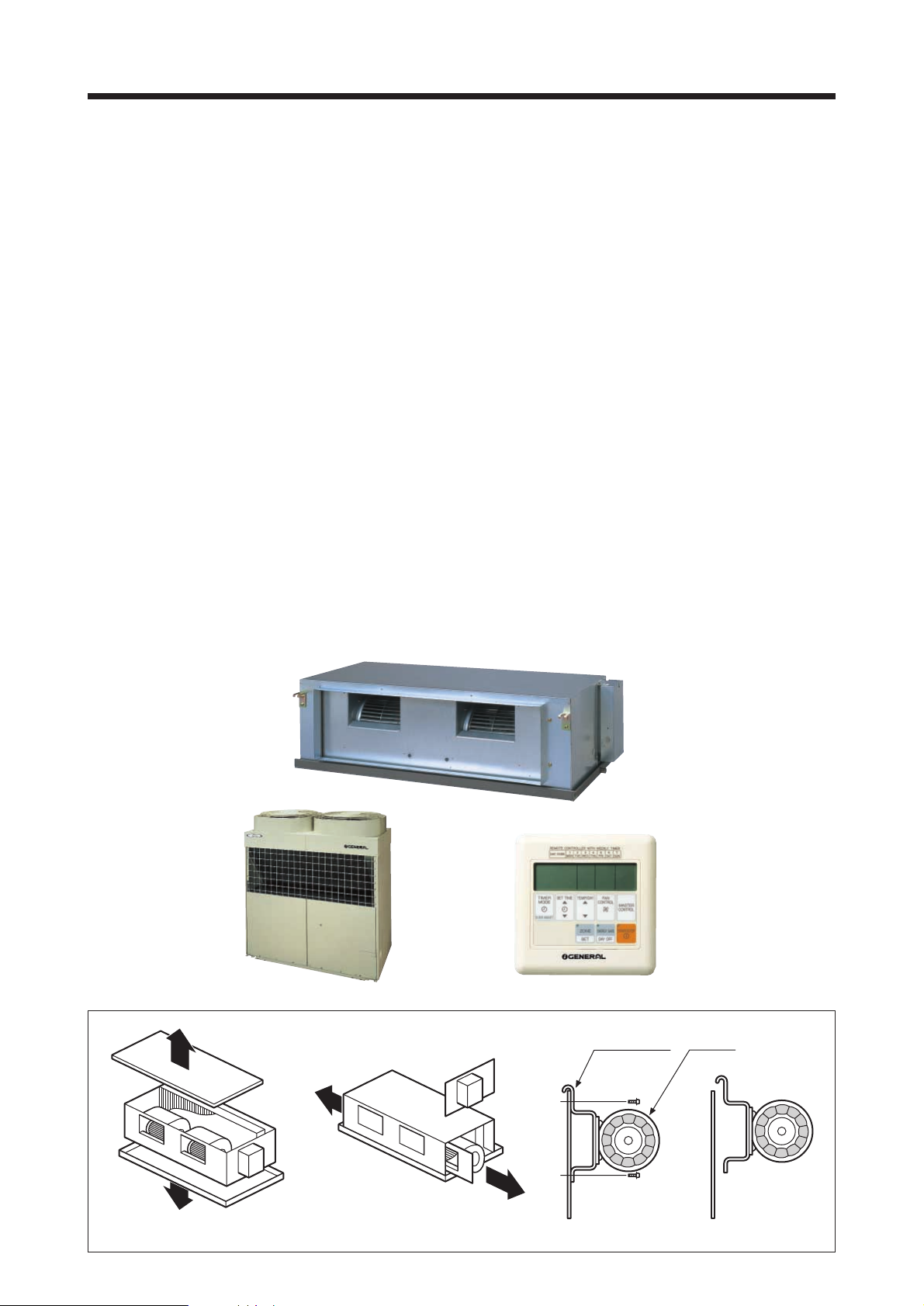
● Easy maintenance
• Fan motor maintenance
Fan motor maintenance can be perfor med from top, bottom, right side, or left side. (Fig. 1)
Fan motor hooks to the panel and is safe and easy to mount and dismount. (Fig. 2)
● Remote sensor unit (Option)
• Temperature sensor unit to be placed in the room
TOP ACCESS
SIDE ACCESS
(BOTH SIDES)
PILOT PLATE MOTOR
BOTTOM ACCESS
Fig. 1
Fig. 2
– 2 –
Page 4
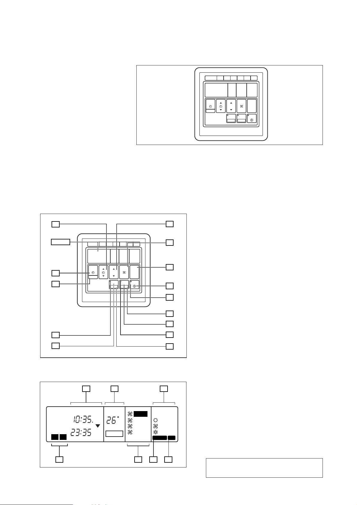
REMOTE CONTROLLER
WIRE REMOTE CONTROLLER WITH WEEKLY TIMER
REMOTE CONTROLLER WITH WEEKLY TIMER
1
DAY CODE
MON2TUE3WED4THU5FRI6SAT
TEMP./DAY
SET TIME
TIMER
MODE
CLOCK ADJUST
FEATURES
Three kinds of timer setup (OFF/ON/WEEKLY) are possible.
Function of weekly timer
• Setting of different on-off time by day
• Setting of set on-off time twice a day
• Setting of time in 5 minute steps
• Timer operation of a reserved day can be temporarily cancelled by pushing the “DAY OFF” button.
• Time setting can be left until the next day.
11
Display
10
9
REMOTE CONTROLLER WITH WEEKLY TIMER
1
DAY CODE
MON2TUE3WED4THU5FRI6SAT
TEMP./DAY
SET TIME
TIMER
MODE
CLOCK ADJUST
ZONE
SET
FAN
CONTROL
ENERGY SAVE
DAY OFF
CONTROL
START/STOP
8
7
Display panel
1615
NON STOP
CLOCK
OFFON
TIMER
TIMER
WEEKLY
2
1
NEXT DAY
OFF
ON
ON
OFF
TEMP.
C
DAY
DAY OFF
MASTER
AUTO
HIGH
MED
LOW
12
13
14
1
2
3
4
5
6
17
HEAT
FAN
COOL
DEFROST TEST
1 START/STOP Button
Pressed to start and stop operation.
2 OPERATION Lamp
Lights during operation and when the timer is on.
3 DAY OFF Button
Temporar y cancellation of one day timer
4 ENERGY SAVE Button
Tur ns energy save mode on and off.
5 ENERGY SAVE Button
Lights when the unit is in the energy save mode.
6 SET Button
Sets the date, hour, minute and on-off time.
7 ZONE Button
Use to turn zone control on and off.
8 ZONE Lamp
Lights when the unit is in the zone control mode.
9 CLOCK ADJUST Button
10 TIMER MODE Button
Changes the timer mode (NON STOP, OFF TIMER,
ON TIMER, WEEKL Y TIMER).
11 SET TIME Button
Sets the current time and on-off time.
12 TEMP./DAY Button
Sets the indoor temperature / day.
#
13 FAN CONTROL Button
14 MASTER CONTROL Button
Selects the operating mode
(HEAT, FAN, COOL).
15 Clock Display
16 Set Temperature / Day Display (TEMP./DAY)
17 Operation Mode Display
18 Timer Mode Display
#
19 Fan Speed Display
20 DEFROST Display
21 TEST Display
ZONE
SET
FAN
CONTROL
ENERGY SAVE
DAY OFF
MASTER
CONTROL
START/STOP
18
2019
21
#NOTE :
This model does not have a fan speed function.
– 3 –
Page 5
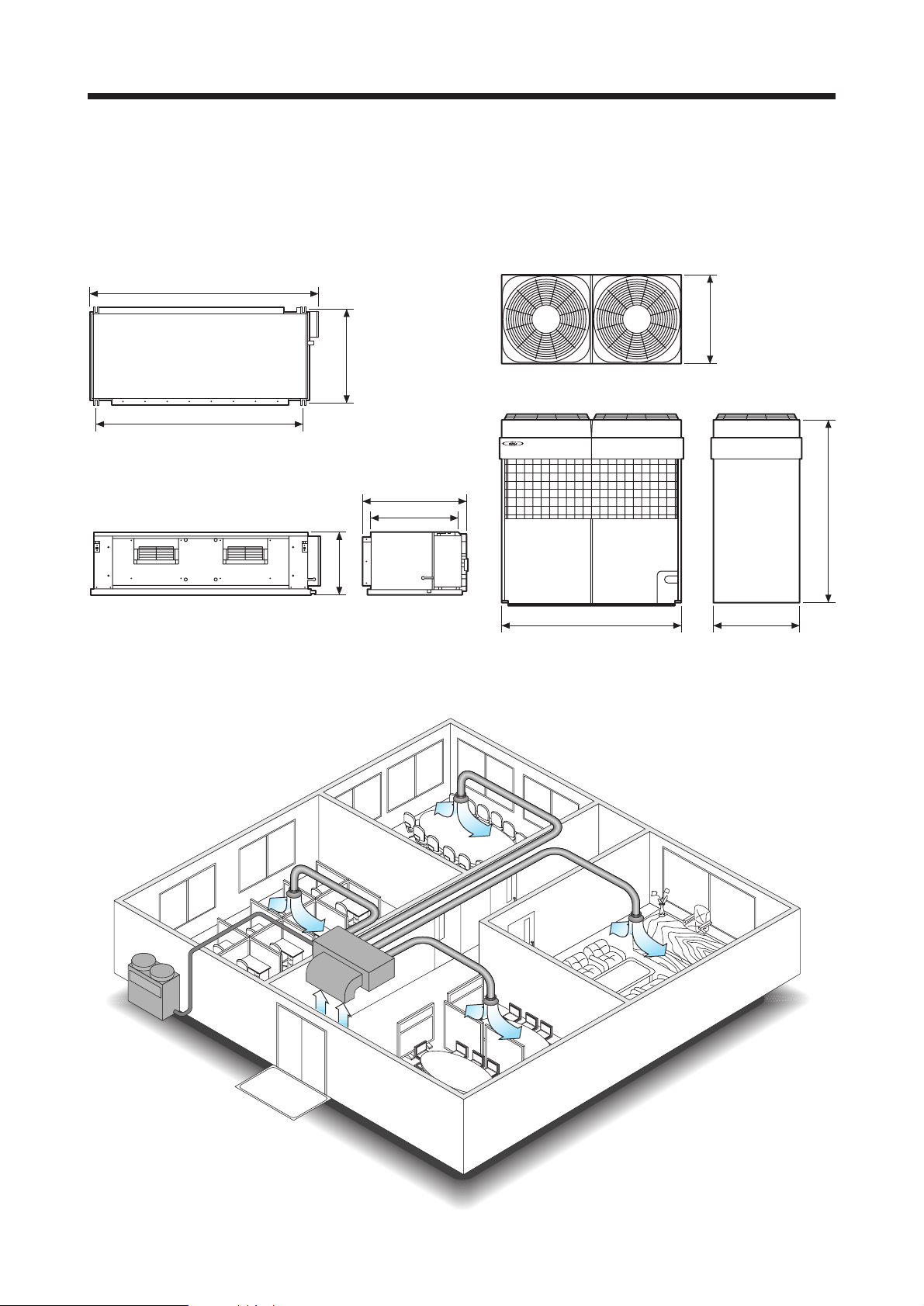
2. DIMENSIONS
■ INDOOR UNIT
1,550
1,410
660
450
700
600
■ OUTDOOR UNIT
(Unit : mm)
650
1,380
● SAMPLE INSTALLATION
1,300 650
– 4 –
Page 6

(Unit : mm)
HOOK METAL
AIR FLOW OUTLET AIR FLOW INLET
CONTROL BOX
SAFETY DRAIN PORT
MAIN DRAIN PORT
38.1 (DRAIN PIPE)
LIQUID : 12.7 FLARE
GAS : 28.58 FLANGE
COUPLING PIPE
1,550 (MAXIMUM)
1,450
600
713 (MAXIMUM)
450
25.4 (SAFETY DRAIN)
– 5 –
Page 7

3. WIRING DIA GRAM
Models : ARG90T
ARG90E
2 31
CN. 15
(FLOAT SWITCH)
1 2
CN. 6
(DRAIN PUMP)
CN. 5
4 35
3 51
FM
FAN
MOTOR
CN. 7
CN. 8
CN. 1
BLACK
GREEN
THERMAL
PROTECTOR
BLUE
BLUE
BLACK
WHITE
RED
1 2
1 2
1 2
1 2
2 31
2 31
WHITE
PURPLE
BLUE
3 2 1 4 5 6
GRAY
GRAY
BLACK
BLACK
CONTROL
BOARD
FUSE
T3.15A 250V
FILTER
BOARD
N
L
CR COMPOSITE
BLUE
BLACK
WHITE
RED
3 2 1 4 5 6
MAGNETIC RELAY
F101
CN. 17
2 13
2 13
THERMISTOR
(PIPE TEMP.)
THERMISTOR
(ROOM TEMP.)
TERMINAL
RED
WHITE
BLACK
TERMINAL
RED
WHITE
BLACK
TERMINAL
BLACK
WHITE
RED
123
TO REMOTE
CONTROL UNIT
12
(N)
3
UNIT
TO OUTDOOR
TSR
TO POWER
– 6 –
Page 8

Model : AOG90EP
RED
W1
INTERNAL
OVERLOAD
PROTECTOR
COMPRESSOR A
1
T
RED
BLACK
RED
BLACK
BELT
BLACK
HEA TER A
T
2
WHITE
WVU32
WHITE
BLACK
BLACK
A1
A2TSR31
T
3
PURPLE
15
43
PURPLE
CR COMPOSITE
MAGNETIC RELAY A
POWER
RELAY A
COMPRESSOR B
PURPLE
1
T
BLACK
BLACK
BELT HEATER B
BLACK
THERMISTOR
(DISCHARGE TEMP.)
THERMISTOR
(OUTDOOR TEMP.)
INTERNAL
OVERLOAD
PROTECTOR
T
3
T
2
WHITE
BLACK
RED
A2
WVU32
A1TSR31
RED
WHITE
BLACK
PURPLE
15
43
BLUE
BLUE
CR COMPOSITE
MAGNETIC RELAY B
POWER
RELAY B
EV
EXPANSION
VALVE COIL
GREEN
GREEN
BLACK
BLACK
WHITE
WHITE
RED
RED
WHITE
YELLOW
ORANGE
BLUE
BROWN
RED
12
FM
BLACK
1
2
PINK
3
CN. 7
4
RED
5
GREEN/YELLOW
E
EARTH
PRESSURE SWITCH
PINK
3
2
PINK
CN. 13
1
3
2
CN. 4
1
3
2
CN. 6
1
CAPACITOR
YELLOW
BLACK
WHITE
RED
BLUE
FAN MOTOR A
FAN
FM
6
5
4
3
CN. 9
2
1
1
2
CN. 10
3
3
2
CN. 18
1
6
5
4
3
CN. 11
2
1
CN. 3
345
PRINTED
CIRCUIT
BOARD
12
CAPACITOR
FAN
YELLOW
BLACK
WHITE
RED
BLUE
CN. 16
345
FAN MOTOR B
PINK
BLUE
1
23 RSTN
POWERUNIT
TERMINAL
GREEN/YELLOW
GREEN/YELLOW
EARTH
– 7 –
Page 9

Model : AOG90TP
RED
W1
INTERNAL
OVERLOAD
PROTECTOR
COMPRESSOR A
1
T
RED
BLACK
RED
BLACK
BELT
BLACK
HEA TER A
T
2
WHITE
WVU32
WHITE
BLACK
BLACK
A1
A2TSR31
T
3
PURPLE
15
43
PURPLE
PURPLE
CR COMPOSITE
MAGNETIC RELAY A
POWER
RELAY A
COMPRESSOR B
1
T
RED
BLACK
RED
BLACK
BELT HEATER B
BLACK
THERMISTOR
(DISCHARGE TEMP.)
THERMISTOR
(PIPE TEMP.)
THERMISTOR
(OUTDOOR TEMP.)
INTERNAL
OVERLOAD
PROTECTOR
T
2
WHITE
WVU32
WHITE
BLACK
BLACK
A2
A1TSR31
T
3
PURPLE
15
43
BLUE
MAGNETIC RELAY B
GREEN
GREEN
BROWN
BROWN
BLACK
BLACK
WHITE
WHITE
RED
RED
POWER
RELAY B
WHITE
YELLOW
ORANGE
EV
EXPANSION
VALVE COIL
BLUE
BROWN
RED
BLUE
CR COMPOSITE
12
FM
BLACK
1
2
PINK
3
CN. 7
4
RED
5
GREEN/YELLOW
E
EARTH
PRESSURE SWITCH
PINK
3
2
PINK
CN. 13
1
SOLENOID COIL
BLACK
3
2
BLACK
CN. 4
1
3
2
CN. 6
1
CAPACITOR
YELLOW
BLACK
WHITE
RED
BLUE
FAN MOTOR A
4WV
FAN
FM
6
5
4
3
CN. 9
2
1
1
2
CN. 10
3
3
2
CN. 18
1
6
5
4
3
CN. 11
2
1
CN. 3
345
PRINTED
CIRCUIT
BOARD
12
CAPACITOR
FAN
YELLOW
BLACK
WHITE
RED
BLUE
CN. 16
345
FAN MOTOR B
PINK
BLUE
1
23 RSTN
POWERUNIT
TERMINAL
GREEN/YELLOW
GREEN/YELLOW
EARTH
– 8 –
Page 10

4. PERFORMANCE DATA
■ COOLING MODEL
COOLING
120
110
100
Indoor
DB/WB (°C)
90
Capacity (%)
80
70
110
100
90
Total input (%)
80
0 5 10 15 20 25 30 35 40 45 50
■ REVERSE MODEL
COOLING
120
110
100
Outdoor DB (°C)
Indoor
DB/WB (°C)
120
110
100
31/22.5
27/19
23/16.5
19/13
31/22.5
27/19
23/16.5
19/13
HEATING
15
20
27
90
Capacity (%)
80
70
110
100
90
Total input (%)
80
0 5 10 15 20 25 30 35 40 45 50
Outdoor DB (°C)
– 9 –
31/22.5
27/19
23/16.5
19/13
31/22.5
27/19
23/16.5
19/13
90
Capacity (%)
80
70
110
100
90
Total input (%)
80
-5 0 5 10 15 20
//////
-6 -2 3 7.5 12 17.5
Outdoor DB (°C)
Indoor
DB (°C)
27
20
15
Page 11

■ COOLING SENSIBLE CAPACITY
INDOOR TEMP.
(°C) 25 30 35 40 45
DB WB Total Sens. Total Sens. Total Sens. Total Sens. Total Sens.
19 13 22.9 17.3 21.8 16.9 20.9 16.4 19.9 15.8 18.5 14.9
23 16.5 24.7 17.9 23.6 17.5 22.9 17.0 21.7 16.4 20.3 15.7
27 19 27.0 21.4 26.1 21.1 25.4 20.9 24.2 20.2 22.7 19.4
31 22.5 29.3 24.8 28.7 24.7 27.9 24.5 26.7 24.1 25.4 23.3
OUTDOOR TEMP. (°C)
■ FAN CURVE
(Pa) (mmAq)
30
(Unit : kW)
250
200
150
25
20
15
External static pressure
100
10
3000
900
415V
380V
3500 4000 4500 5000 (m
1000 1100 1200 1300
Air Flow
■ CAPACITY BY AIR FLOW
30.0
25.0
20.0
Capacity (kW)
COOLING
Standard
3
/h)
/Sec)(
35.0
30.0
25.0
Capacity (kW)
HEATING
3000
900 1000 1100
4000 5000 6000
1200 1300 1400 1500 1600
(m
3
/h)
/Sec)(
Air Flow
■ OUTLET AIR TEMPERATURE
COOLING
4000 5000 6000
1200 1300 1400 1500 1600
Air Flow
(m
3
/h)
/Sec)(
– 10 –
Temp (°C)
20.0
15.0
10.0
5.0
3000
900 1000 1100
Temp (°C)
3000
50.0
45.0
40.0
35.0
3000
4000 5000 6000
900 1000 1100
4000 5000 6000
900 1000 1100
1200 1300 1400 1500 1600
Air Flow
HEATING
1200 1300 1400 1500 1600
Air Flow
3
/h)
(m
/Sec)(
(m3/h)
/Sec)(
Page 12

5. OPERATION DETAILS
■ TEMPERATURE AND HUMIDITY RANGE
Cooling Mode *Heating Mode
OUTDOOR
COOLING MODEL Approx. 00 to 52°C –––––
TEMPERATURE
HEAT & COOL MODEL
(Reverse Cycle)
INDOOR TEMPERATURE Approx. 18 to 30°C Approx. below 30°C
INDOOR HUMIDITY Approx. 80% or less –––––
• Do not use this unit for any purpose other than the cooling, (*) heating,
dehumidifying and circulating air of rooms in ordinary dwellings.
■ REFRIGERANT CHARGE
Actual pipe length
Full charge amount 7,000g 8,000g 9,000g 100g/m
HEAT & COOL MODEL
30m 40m 50m Additional
(99ft) (132ft) (164ft) refrigerant (R407C)
(247 oz) (282 oz) (317 oz) (3.5 oz / 3.3 ft)
Approx. 00 to 46°C Approx. -10 to 21°C
Full charge amount 6 ,000g 6,500g 7,000g 50g/m
COOLING MODEL (212 oz) (229 oz) (247 oz) (1.8 oz / 3.3 ft)
Do not purge the air with refrigerants but use a vacuum
pump to vacuum the installation! There is no extra refrigerant in the outdoor unit for air purging!
Use a vacuum pump for R407C exclusively. Using the
same vacuum pump for different refrigerant ma y damage the vacuum pump or the unit.
When moving and installing the air conditioner, do not
mix gas other than the specified refrigerant R407C
inside the refrigerant circuit.
When charging the refrigerant R407C, alwa ys use an
electronic balance for refrigerant charging (to measure
the refrigerant by weight).
When charging the refrigerant,
take into account the slight change
in the composition of the gas and
liquid phases, and always charge
from the liquid phase side whose
composition is stable.
Add refrigerant from the charging valve after the
completion of the work.
Use a brand-new refrigerant piping when replacing the
air conditioner using the refrigerant except R407C and
R410A.
Gas
Liquid
Gauge manifold
LO
HI
Use a clean gauge manifold and charging hose
for R407C exclusively.
Vacuum pump
Service hose
– 11 –
Page 13

6. INSTALLATION INSTRUCTIONS
■ INDOOR UNIT
• SERVICE SPACE
Leave the space reguired to service the air conditioner. (Fig.1)
(1) If a service hole is provided at the bottom of the product.
Fig.1
200
890
40030
1,920
(2) If the service hole referenced in (1) is not provided.
900 900
• INSTALLING DRAIN PIPE
Position of drain piping and refrigerant piping.
404
95
40
318
60
50
200
427
50
Service hole
Unit : mm
Unit : mm
235
• INSTALLING THE DUCT
Follow the procedure in the following figure to install the duct.
Flange positions for connecting the duct.
*20 370 14
*25
*Spacing between flange and drain pan
Install the air inlet grille for air circulation.
The correct temperature cannot be detected.
(Room)
15
35
2 x 160 pitch = 320
350
Air Outlet Grille
1,250
Inlet port flange
75 Outlet port flange
7 x 150 pitch = 1,050
Unit
Air Inlet Grille
Unit : mm
■ OUTDOOR UNIT
Provide the space shown in Fig.2 so that the air flow is not
blocked.
• Installing the unit individually
Fig. 2
10mm or more
Safety drain pipe
ø25.4mm (O.D.)
Main drain pipe
ø38.1mm (O.D.)
The installed drain pipe should have a downward gradient of 1/50
to 1/100. Make sure that the drain pipe is installed without rises.
Use general hard polyvinylchloride pipe (VP25) and connect
it with adhesive (polyvinylchloride) so that there is no leakage. Do not perform air bleeding.
Main drain
On the main drain, provide one trap near the indoor unit.
Unit H1=100 mm (Approx.)
H2=50 to 100 mm
Drain pipe
H1H2
Trap
Safety drain
There is no need to provide a trap for the safety drain. If the
safety drain is connected to the main drain, make the connection below the main trap.
Unit
Main
Drain Pipe
Safety
Once installation is complete, check the flow of drain water.
Front
H (1,200 mm or less) h
500mm
or more
10mm or more
L1 L2
Front air
intake
Top blower
outlet
200mm
or more
Rear
air
intake
H (1,200 mm or less) h
• There is no limit to the height of the side wall.
• The height of the wall (H) at the front and rear should be
1,200mm or less.
• If the wall height exceeds 1,200mm, add dimension (h) to
the respective service space dimensions L1 and L2.
– 12 –
Page 14

7. SPECIFICATIONS
TYPE
Model
Input Power V/ /Hz 380 - 415 / 3 / 50 380 - 415 / 3 / 50
Capacity
Ampacity
Input Watts
Starting Current A 63 63
Moisture Removal /h 7.5 7.5
E.E.R.
Fan Speed
Air Flow
Standard Static Pressure Pa 200
Dimensions
H x W x D
Weights Net / Gross
Refrigerant Type –– R407C
Connection Method / Pipe Size –– Flange / 28.58 (Large) Flare / 12.70 (Small)
Max. Pipe Length / Height m 50 / 30
Operation Range
Indoor Unit ARG90E ARG90T
Outdoor Unit AOG90EP AOG90TP
Cooling
Heating
Cooling
Heating ––– 19.5 - 19.5
Cooling
Heating ––– 12.2 - 12.5
Cooling
Heating ––– 2.36 - 2.36
Indoor
Outdoor 730
Indoor
Outdoor
Indoor 450 x 1,550 x 700
Net
Outdoor
Indoor 550 x 1,750 x 825
Gross
Outdoor 1,535 x 1,400 x 700
Indoor
Outdoor 243 / 280 245 / 282
Cooling
Heating –– -10 to 21
kW 24.8 - 25.4 24.8 - 25.4
BTU/h 84,500 - 86,500 84,500 - 86,500
kW ––– 28.9 - 29.5
BTU/h ––– 98,500 - 100,500
A
kW
kW/kW
r.p.m.
3
m
/h
/s)
(
mm
kg
°C
COOLING ONLY TYPE COOLING & HEATING TYPE
18.3 - 17.6 19.5 - 19.5
11.0 - 11.0 12.2 - 12.5
2.25 - 2.31 2.03 - 2.03
0 to 52 0 to 46
DUCT TYPE AIR CONDITIONER
1,140 When static pressure is 200Pa
4,300 (1,194) When static pressure is 200Pa
5,800 (1,611)
1,380 x 1.300 x 650
85 / 100
– 13 –
Page 15

0009J-904-1750
September 2000 Printed in Japan
 Loading...