

Page 1

S PLIT T Y PE AIR
CON DITIO N E R (50Hz)
DUCT
type
Models Indoor unit Outdoor unit
ARG90ELC3 AOG90EPD3L
ARG90TLC3 AOG90TPC3L
ARY90ELC3 AOY90EPD3L
ARY90TLC3 AOY90TPC3L
CONTENTS
SPECIFICATIONS . . . . . . . . . . . . . . . . . . . . . . . . . . . . . .
OUTLINE AND DIMENSIONS
CIRCUIT DIAGRAM
INDOOR P. C. BOARD CIRCUIT DIAGRAM
OUTDOOR P. C. BOARD CIRCUIT DIAGRAM
ERROR CONTENTS
REFRIGERANT SYSTEM DIAGRAM
DISASSEMBLY ILLUSTRATION
PARTS LIST . . . . . . . . . . . . . . . . . . . . . . . . . . . . . . . . . 22
. . . . . . . . . . . . . . . . . . . . . . . . . . . .
. . . . . . . . . . . . . . . . . . . . . . . . . . . .
. . . . . . . . . . . . . . . . . . . .
. . . . . . . .
. . . . .
. . . . . . . . . . . . .
. . . . . . . . . . . . . . . . .
11
13
14
15
1
2
5
9
Page 2
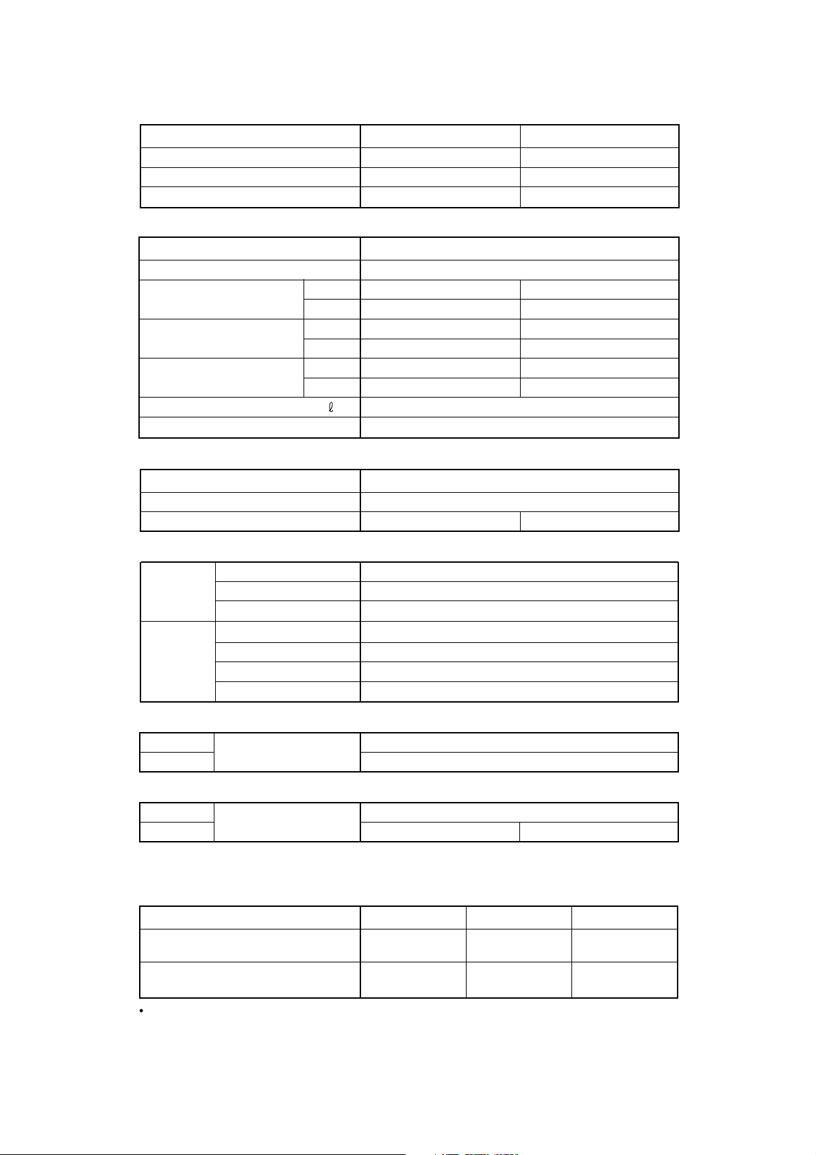
S PE C IFIC ATION S
IN DOOR U N IT AR G90E LC 3, AR Y90E LC 3 AR G90T LC 3, AR Y90T LC 3
OUT DOO R U NIT AOG90EPD 3L, AOY90E PD 3L AOG90TPC 3L, A OY 90T PC 3L
COO LIN G C AP AC IT Y (kW ) 24.8 - 25.4 24.8 - 25.4
HE ATIN G CA PA CIT Y (kW )
-----
E LE CT RICAL DATA
PO W ER SOU R CE (V ) 380 - 415
FR E QU EN CY (H z) 50
R UN NIN G CU RR E NT (A )
IN PU T WA TTS (kW )
E ER (kW /kW )
M OIS T UR E R E MO VA L ( /hr) 7. 5
AIR CI RC UL AT IO N-H i (m
COO LIN G 19.5 - 19.5 19.5 - 19.5
HE ATIN G
COO LIN G 12.2 - 12.5 12.2 - 12.5
HE ATIN G
COO LIN G 2. 03 - 2.03 2. 03 - 2.03
HE ATIN G
3
/hr) 4, 300
-----
-----
-----
COM PR ES S OR
28.9 - 29.5
19.5 - 19.5
12.2 - 12.5
2. 37 - 2.36
T YP E He rmetic typ e, 2 pole, 3-phase, Induction moto r, Scroll
COD E ZR T122 K3E-T FD
R EF RIG ER ANT (R 407 C) (g) 7, 0006, 000
FA N M OT OR
IN DOOR
OUT DOO R
T YP E MF A-9 0GQH
PO W ER SOU R CE (V ) 38 0 - 415
HI-S PE E D
T YP E
PO W ER SOU R CE
HI-S PE E D
LO-S PE ED
(r.p .m.) 1,140
M FB -90F TH
(V )
(r.p .m.)
(r.p .m.)
220 - 240
730
360
DIM EN S IONS
IN DOOR
OUT DOO R
H x W x D ( mm )
450 x 1,550 x 700
1, 380 x 1 ,300 x 650
W EIG HT S
IN DOOR
OUT DOO R
G RO S S / NE T (kg)
280 / 243 282 / 245
100 / 85
R EF RIG ER AN T CHA RG E (F UL L CHA RG E AM OUN T) (R 407C)
PI PE LE N GT H
AR G90E LC 3 / A OG 90E PD 3L
AR Y90E LC 3 / A OY 90E PD 3L
AR G90T LC 3 / A OG 90T PC 3L
AR Y90T LC 3 / A OY 90T PC 3L
30 m 40 m 50 m
6, 000g 6, 500g 7,000 g
7, 000g 8, 000g 9,000 g
The above list shows values at the external static pressure of 20 mm Aq. (196 Pa).
12003.10.21
Page 3
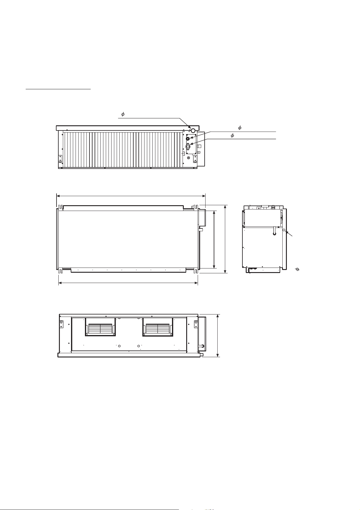
O U T L IN E A N D DIM E N S IO N S
Models : ARG90ELC3
ARG90TLC3
ARY90ELC3
ARY90TLC3
(Unit : mm)
38.1 (DRAIN PIPE)
LIQUID : 12.7 FLARE
GAS : 28.58 FLANGE
1,550 (MAXIMUM)
1,450
600
713 (MAXIMUM)
450
25.4 (SAFETY DRAIN)
22003.09.19
Page 4
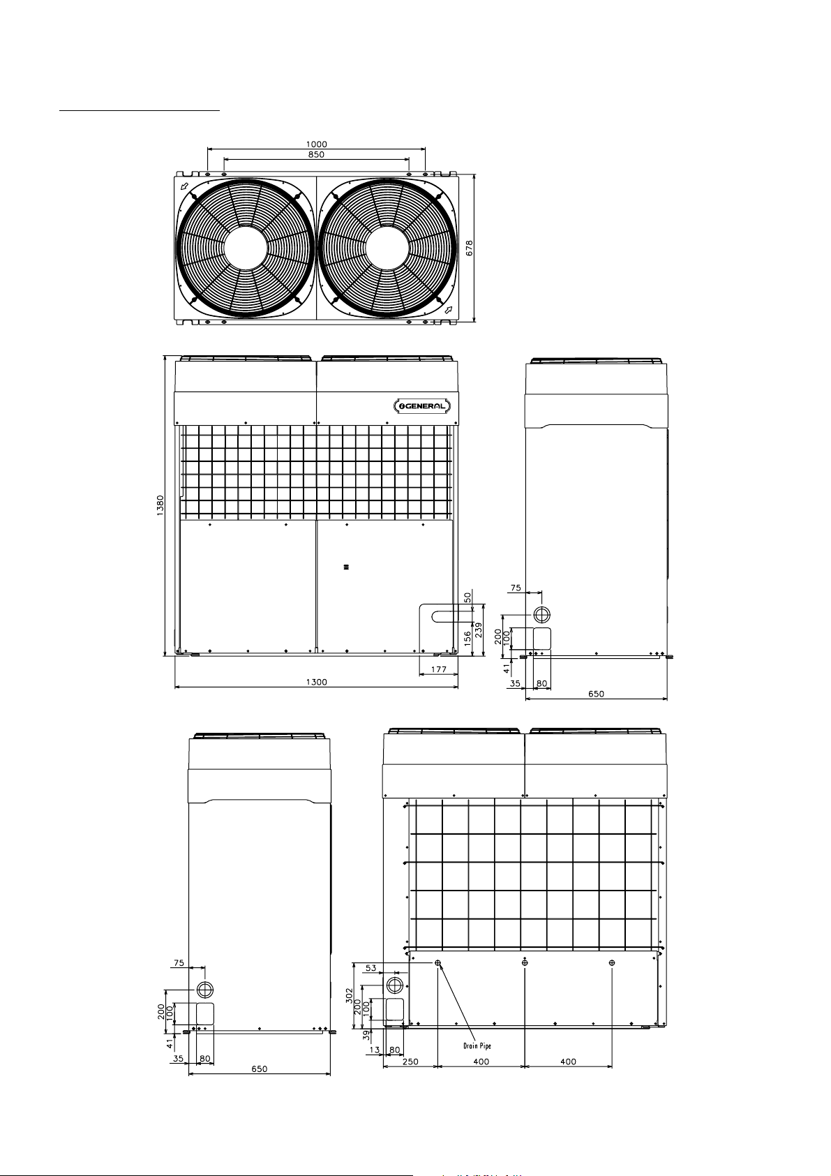
Models : AOG90EPD3L
AOG90TPC3L
AOY90EPD3L
AOY90TPC3L
(Unit : mm)
32003.09.19
Page 5
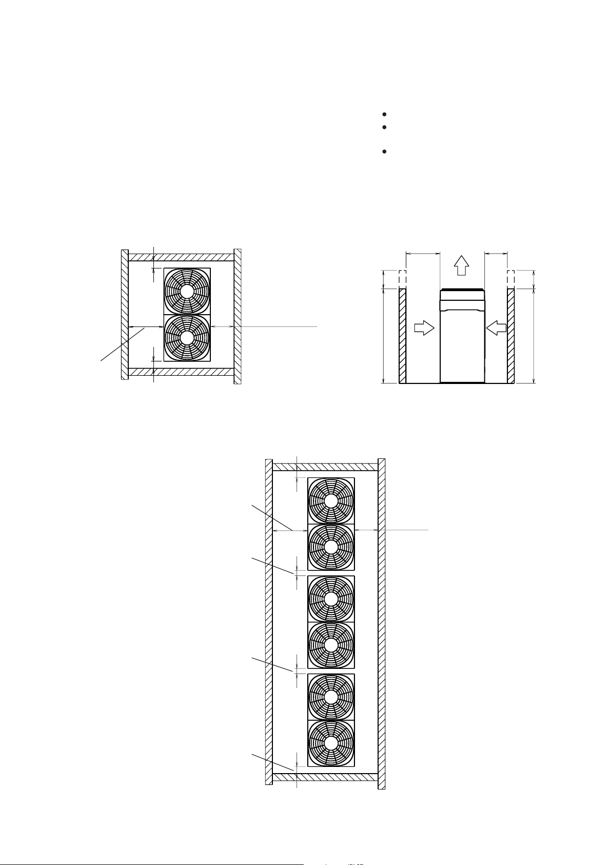
SERVICE SPACE FOR OUTDOOR UNIT
Top air outlet
Back
intake port
H (1200mm) h
H (1200mm) h
Front
intake port
L2L1
10mm or more
10mm or more
200mm or more
500mm
or more
FRONT
Height of side wall is free.
Height (H) of front wall is
less than 1,200mm.
When total height of outdoor
unit is lower than front wall,
add dimension h to service space
for dimensions L1 and L2.
10mm or more
10mm or more
10mm or more
10mm or more
200mm
or more
500mm or more
FRONT
42003.09.19
Page 6
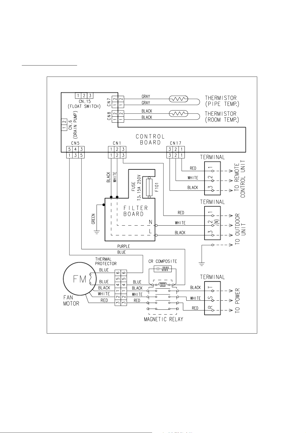
Models : ARG90ELC3
ARY90ELC3
CIRCUIT DIAGRAM
52003.10.17
Page 7
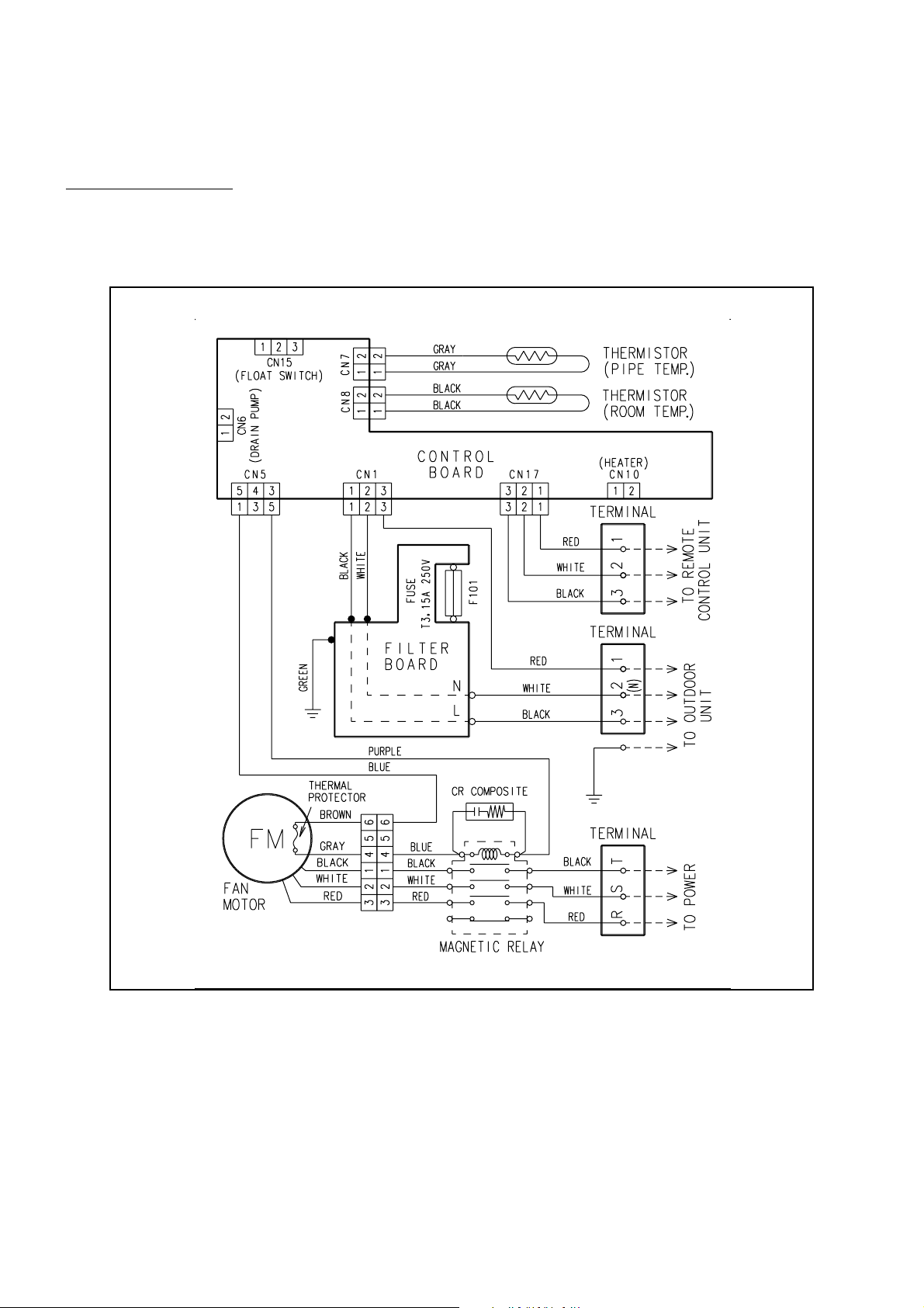
Models : ARG90TLC3
ARY90TLC3
62003.10.17
Page 8
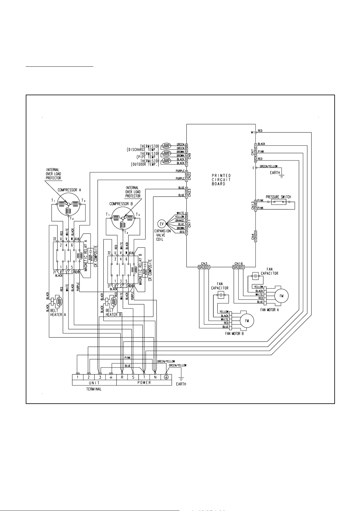
Model :
AOG90EPD3L
AOY90EPD3L
72003.10.17
Page 9

Model :
AOG90TPC3L
AOY90TPC3L
82003.10.17
Page 10

Model : ARG90ELC3
ARY90ELC3
IN D O O R PR IN T E D C IR CU IT B OA R D
CIR C U IT DIA G R A M
CONTROLLER PCB ASSEMBLY (MAIN PCB)
ROOM TEMPERATURE THERMIS TOR
POWER SUPPLY PCB
ROOM TEMP. CORRECTION (COOL)
FREEZING PREVENTION
TEMPERATURE CHANGER
SWITCHING TRANSFORMER
HEAT EXCHANGER THERMI STOR
ELECTROMAGNETIC
SWITCH A
415V/380V
50Hz
EZÐ0001WSEÐR
CR COMPOSITE
92003.10.17
Page 11

Model : ARG90TLC3
ARY90TLC3
CONTROLLER PCB ASSEMBLY (MAIN PCB)
ROOM TEMPERATURE THERMIS TOR
POWER SUPPLY PCB
ROOM TEMP. CORRECTION (COOL)
FREEZING PREVENTION
TEMPERATURE CHANGER
SWITCHING TRANSFORMER
HEAT EXCHANGER THERMI STOR
ELECTROMAGNETIC
SWITCH A
415V/380V
50Hz
EZÐ0001HSEÐR
CR COMPOSITE
102003.10.17
Page 12

Model : AOG90EPD3L
AOY90EPD3L
OU T D O O R PR IN T E D C IR C U IT B O A R D
CIR C U IT D IA G R A M
CONTROLLER PCB ASSEMBLY (MAIN PCB)
EXPANSION VALVE-A
415V/380V
50Hz
YELLOW
WHITE
RED
BLUE
YELLOW
WHITE
RED
BLUE
WHITE
RED
BLUE
WHITE
RED
BLUE
OUTDOOR T EMP. THERMIS TOR
DISCHARGED TEMP. THER MISTOR A
PIPE TEMP. THERMIS TOR A
BLACK
BLACK
CR COMPOSITE
ELECTROMAGNETIC
SWITCH A
RED
WHITE
BLACK
ELECTROMAGNETIC
SWITCH B
RED
WHITE
CR COMPOSITE
BLACK
BLACK BLACKBLACK BLACK
112003.10.17
Page 13

Model : AOG90TPC3L
AOY90TPC3L
CONTROLLER PCB ASSEMBLY (MAIN PCB)
EXPANSION VALVE-A
415V/380V
50Hz
YELLOW
WHITE
RED
BLUE
YELLOW
WHITE
RED
BLUE
WHITE
RED
BLUE
WHITE
RED
BLUE
OUTDOOR T EMP. THERMIS TOR
DISCHARGED TEMP. THER MISTOR A
PIPE TEMP. THERMIS TOR A
BLACK
BLACK
CR COMPOSITE
ELECTROMAGNETIC
SWITCH A
WHITE
BLACK
RED
ELECTROMAGNETIC
SWITCH B
RED
WHITE
CR COMPOSITE
BLACK
BLACK BLACKBLACK BLACK
122003.10.17
Page 14

NON STOP
CLOCK
TEMP
AUTO
TIMER
MODE
SET
START/STOP
CLOCK ADJUST
SET TIME TEMP./DAY FAN
CONTROL
MASTER
CONTROL
21
HIGH
COOL
DEFROST
DAY OFF
AUTO
TIMER
MODE
SET
START/STOP
CLOCK ADJUST
SET TIME TEMP./DAY FAN
CONTROL
MASTER
CONTROL
21
DAY OFF
ENERGY SAVE ENERGY SAVE
ZONE
Error cord
Error contents
Communication error
(indoor unit remote controller)
Communication error
(indoor unit outdoor unit)
Room temperature sensor open
Room temperature sensor shortcircuited
Indoor heat exchanger temperature sensor open
Indoor heat exchanger temperature sensor
shortcircuited
Outdoor heat exchanger temperature sensor
open
Outdoor heat exchanger temperature sensor
shortcircuited
Power source connection error
Float switch operated
Outdoor temperature sensor open
Outdoor temperature sensor shortcircuited
Discharge pipe temperature sensor open
Discharge pipe temperature sensor shortcircuited
Outdoor high pressure abnormal
Discharge pipe temperature abnormal
Model abnormal
Indoor fan abnormal
Outdoor signal abnormal
Outdoor EEPROM abnormal
Error contents LED1 LED2 LED3 LED4 LED5 LED6
Signal abnormal
Indoor unit abnormal
Discharge pipe
temperature abnormal
Outdoor heat exchanger
temperature abnormal
Outdoor temperature
abnormal
Power source
connection error
EEPROM abnormal
Outdoor high pressure
abnormal
Discharge pipe
temperature abnormal
: 0.5s ON / 0.5s OFF (flash) : OFF
: 0.1s ON / 0.1s OFF (flash) : Indefinite
ERROR CONTENTS
1. REMOTE CONTROLLER 2. OUTDOOR UNIT
When EE : EE blinks at the current time display, there is an
error inside the air conditioner. If the SET TIME button ( )
and TEMP./DAY button ( ) are pressed simultaneously for
more than three seconds, the self diagnosis check will start
and the error contents will be displayed at the current time
display. When the operation lamp lights, press the
START/STOP button and after operation lamp goes off,
perform the same operation. Process the error contents by
referring to (Table 1).
Stop operation.
Table 1
When the outdoor temperature drops, the outdoor unit's fans
may switch to low speed, or one of the fans may stop
intermittently.
ERROR : Heat & Cool model (Reverse cycle) only
The LED lamps operate as follows (Table 2) according to the
error contents.
The LED lamps are on the outdoor unit board.
ARG90ELC3 / AOG90EPD3L
ARG90TLC3 / AOG90TPC3L
ARY90ELC3 / AOY90EPD3L
ARY90TLC3 / AOY90TPC3L
Table 2
To stop test running, press the START/STOP button.
For the operation method, refer to the operating manual and
perform operation check.
Check that there are no abnormal sounds or vibration
sounds during test running.
2003.06.17
When the fault is cleared, the LED lamp goes off.
However, for discharge pipe temperature abnormal and high
pressure abnormal, the LED lamp lights continuously for 24
hours, as long as the power is not turned off.
ERROR LED DISPLAY LAYOUT
132003.10.17
Page 15

R E F R IG E R A N T S Y S TE M DIA G R A M
Cooling
Heating
Dryer
Check Valve
Pressure SW
4Way Valve
Accumulator
Condenser
Tandem
Compressor
Evaporator
FlangeRefrigerant Pipe
28.58 mm (1-1/8")
Electronic
Expansion
Valve
Charging Valve
Strainer
FlareCapillary TubeFlange
Refrigerant Pipe
12.7 mm (1/2")
Models : ARG90ELC3 / AOG90EPD3L
ARY90ELC3 / AOY90EPD3L
Pressure SW
Condenser
Tandem
Compressor
Accumulator
Cooling
Models : ARG90TLC3 / AOG90TPC3L
ARY90TLC3 / AOY90TPC3L
28.58 mm (1-1/8")
Check Valve
Dryer
Electronic
Expansion
Valve
FlangeRefrigerant Pipe
Evaporator
Strainer
Charging Valve
Refrigerant Pipe
12.7 mm (1/2")
FlareFlange
142003.10.17
Page 16

DISASSEMBLY ILLUSTRATION
Models : AOG90EPD3L
AOG90TPC3L
AOY90EPD3L
AOY90TPC3L
2
477
4
39
117-3
42
167
653
761
164
132
176
226
134
133
41
45
527
45
356
355
9
762
160
166
289
949-2
361
12
949-1
100
152003.10.17
Page 17

Models : AOG90EPD3L
AOY90EPD3L
2
162003.10.17
Page 18

Model : AOG90TPC3L
AOY90TPC3L
450
334
344
172
196-1
652-1
343
16-2
15
918
184-1
919-2
82
245
195
16-1
187
678
829
810
86
85
272
69-3
646
21
354
327
333
320-1
87
825
790-1
347
966
809
26
964
46
790-2
55
816
363
172003.10.17
Page 19

Models : AOG90EPD3L
AOG90TPC3L
AOY90EPD3L
AOY90TPC3L
32
34
942
381-2
381-3
405
185
376
236
196-2
815-1
815-2
407
982-2
982-1
880-1
791
182003.10.17
Page 20

Models : ARG90ELC3
ARG90TLC3
ARY90ELC3
ARY90TLC3
468
653-2
287
10
995
468
996
160
324
761
329
652-1
514
69
735
184-1
235
967
51
86
674
234
625
995
64
405
146
468
273
495
468
287
192003.10.17
Page 21

Models : ARG90ELC3
ARG90TLC3
ARY90ELC3
ARY90TLC3
75
477
495
126
56-2
45-1
468
477
653-2
164
468
477
109
109
56-1
477
202003.10.17
Page 22

Models : ARG90ELC3
ARG90TLC3
ARY90ELC3
ARY90TLC3
287
320-1
233-1
240
875
287
943
187
380
223
824-3
381-4
466
815-3
815-1
815-2
233-1
236
982-2
982-1
791
982-2
982-1
195
287
212003.10.17
Page 23

PARTS LIS T
IN DOOR UN IT
Ref.
No.
10 Front Panel Assy 9364635002 9364635002
45-1 Bracket (Motor) Assy 9364630007 9364630007
51
56-1 Sirocco Fan-R 9364665016 9364665016
56-2 Sirocco Fan-L 9364665023 9364665023
64 Left Panel 9364650005 9364650005
69 Right Panel 9364649009 9364649009
75 Fan Panel 9364629001 9364629001
86 Gasket 9363272000 9363272000
109 Casing Assy 9364660004 9364660004
126 Motor Plate Assy 9364632001 9364632001
146 Evaporator Assy 9370825015 9370825015
160 Drain Pan Assy 9364652023 9364652023
164 Fan Motor Assy-In 9601004004 9601004004
184-1 Thermo. Spring-A 313728262708 313728262708
187 Clamp No.1219 313361271706 313361271706
195 Clamp SKB-100 313361275805 313361275805
223 Control Box Metal 9365185001 9365185001
233-1 Plate (Box) 9365146002 9365146002
234 Thermistor Assy-Room 9703299056 9703299056
235 Thermistor Assy-Pipe 9703297021
236 Controller PCB Assy 9704557377
240 Remote Control Unit 9703173066 9371438030
273 Rear Panel Assy 9364642000 9364642000
287 Cap (Power) 9352173011 9352173011
320-1 Wire Clamp Metal 313483219905 313483219905
324 Top Plate 9364634005 9364634005
Nut
Description
0700005091 0700005091
9704557520
Part No.
ARG90ELC3 ARG90TLC3
ARY90ELC3 ARY90TLC3
9703297021
When you order parts, please make a photocopy of this page
and fill the number of the parts in the "Order" column.
Ord.
Ref.
Q'ty
No.
329 Coupling Pipe Assy 9365347003 9365347003
380 Locking Spacer KGLS-6S 313209391403 313209391403
381-4 Locking Spacer KGPS-6S 0600118075 0600118075
405 Panel Side 9364648002 9364648002
466 Clamp NK-4N 313714328805 313714328805
468 Nut-A M8 9356998009 9356998009
477 Bellmouth 9364664002 9364664002
495 Clamp No.2U46 9352715006 9352715006
514 Control Box Cover Metal 9365186008 9365186008
625 Cord Bushing 9359240006 9359240006
652-1 Therm. Holder Pipe 313806262805 313806262805
653-2 Bolt HLSJ8025ZV 0700190018 0700190018
674 Bolt LSM10045 0700145117 0700145117
735 Distributor Assy 9365343005 9365343005
761 Side Panel-R Assy 9365147009 9365147009
791 Magnetic Relay 9900002015 9900002015
815-1 Terminal 3P 9356488005 9356488005
815-2 Terminal 3P 9363276046 9363276046
815-3 Terminal 3P 9703345012 9703345012
824-3 Fuse 0600222512 0600222512
875 Filter PCB Ass y 9704561145 9704561145
943 Wire Clamp 0600231019 0600231019
967 Bonnet-B 313045417959 313045417959
982-1 Cord Clamp 9356857009 9356857009
982-2 Cord Clamp-B 9356858006 9356858006
995 Beam 9364647005 9364647005
996 Drain Pan (S ) Ass y 9364893013 9364893013
Description
ARG90ELC3 ARG90TLC3
ARY90ELC3 ARY90TLC3
Part No.
ARG90ELC3
ARG90TLC3
ARY90ELC3
ARY90TLC3
Ord.
Q'ty
222003.10.17
Page 24

AOG90EPD3L
AOG90TPC3L
AOY90EPD3L
AOY90TPC3L
OU T DOO R U NIT
Ref.
No.
2 Fan Cover 9366142010 9366142010
4 Emblem-Rear "FUJITSU" 9371388014 9371388014
4 Emblem-Rear "GENERAL" 313791088308 313791088308
9 Rear Panel, Painted 9361712027 9361712027
12 Base Assy 9372336014 9372336014
15 Dryer 9369978012 9369978012
16-1 Condenser-A Assy 9370620016 9370620016
16-2 Condenser-B Assy 9370621013 9370621013
20 Discharge Pipe Assy 9365569009 ---- 21 Discharge Pipe - B Assy ---- - 93 65567005
26 Compressor Cover-A 9361935006 9361935006
32 Control Box 9361713000 9361713000
34 Capacitor (Fan Motor) 9703306037 9703306037
39 Propeller Fan 9361726000 9361726000
41 Fan Motor Assy-Outer 9601698012 9601698012
42 Bracket Panel (Motor) 9361703001 9361703001
45 Bracket (Motor) 9361701007 9361701007
46 Compressor Assy 9367378005 9367378005
55 Special Nut M8 313252257701 313252257701
69-3 Bolt , Hex.Socket 301210060360 301210060360
82 Check Joint Assy 9363886009 9363886009
85 Valve Plate 9363063004 9363063004
86 Gasket 9363272000 9363272000
87 Bracket (Compressor) 9361694002 9361694002
100 Base Foot , Painted 9361688025 9361688025
117-3 Special Washer M6 313306391007 313306391007
132 Front Protection Net 9366144014 9366144014
133 Front Panel - L 9361709027 9361709027
134 Front Panel - R 9361710047 9361710047
160 Drain Pan 9361700000 9361700000
164 S eparate Wall - Upper 9361693005 9361693005
166 S eparate Wall - L 9361695009 9361695009
167 S eparate Wall - R 9361696006 9361696006
172 Pipe Cover 9363470000 9363470000
176 Bracket (Valve) - A 9368955007 9368955007
184-1 Thermostat Spring-A 313728262708 313728262708
185 R ubber Bushing 313005066051 313005066051
187 Clamp No.1219 313361271706 313361271706
195 Clamp SKB - 100 313361275805 313361275805
196-1 Clamp SKB - 3M 312300787605 312300787605
196-2 Clamp SKB - 150 313035356905 313035356905
226 Reinforcement (Separate Wall) 9361697003 9361697003
236 Controller PCB Ass y 9704764102
245 Condensing Pipe - M 9367200009
272 S trainer 9361931008 9361931008
289 R einforcement (S ide Panel) 9361704008 9361704008
320-1 Wire Clamp Metal 313483219905 313483219905
Description
AOG90EPD3L AOG90TPC3L
AOY90EPD3L AOY90TPC3L
9704764164
Part No.
9367200009
When you order parts, please make a photocopy of this page
and fill the number of the parts in the "Order" column.
Ord.
Ref.
Q'ty
No.
327 S uction Pipe - A 9365599006 9365599006
333 Accumulator 9371828015 9371828015
334 S uction Pipe - B -- -------- 9361894006
343 S olenoid Coil ------ ---- 9703342011
344 4-Way Valve ---------- 9703270000
347 Noise Insulation - D 313712304109 313712304109
354 Pressure Switch 9703667008 9703667008
355 Bracket (Condenser) - L 9361698000 9361698000
356 Bracket (Condenser) - R 9361699007 9361699007
361 Bushing 9361725003 9361725003
363 Bracket Panel (Comp.) 9361691018 9361691018
376 Bracket (Control Box) 9361727007 9361727007
381-2 Locking Spacer KGLS-8S 0600035020 0600035020
381-3 Locking Spacer KGPS-8S 0600118051 0600118051
405 Clamp No.1763 313816345304 313816345304
407 Clamp(Cable) No.1259 313739340109 313739340109
450 Discharge Pipe - A ----- 9367217007
477 Bellmouth 9361721005 9361721005
527 Condenser Guard 9366143017 9366143017
646 Compressor Cover - B 9361936003 9361936003
652-1 Thermistor Holder Pipe 313714262805 313714262805
653 Bolt, For Fan Motor 0700145087 0700145087
678 Bracket (Thermistor) 313557406106 313557406106
761 S ide Panel - R, Painted 9361706026 9361706026
762 S ide Panel - L, Painted 9361705029 9361705029
790-1 Belt Heater - A 9361140042 9361140042
790-2 Belt Heater - B 9361140059 9361140059
791 Magnetic Relay 9900078010 9900078010
809 Ball Valve - A 9371799025 9371799025
810 Ball Valve - B 9361938007 9361938007
815-1 Terminal 5P 9363275018 9363275018
815-2 Terminal 4P 9363276015 9363276015
816 Wire Clamp Metal 313584219902 313584219902
825 Expansion Valve Assy 9366558002 9365566008
829 J oint Pipe Assy 9362922005 9361886001
880-1 Network (C - R ) 9700987017 9700987017
918 Thermistor Assy 9900125011 9900125011
919-2 Expansion Valve Coil 9361930001 9361930001
942 Control Box Cover 9361716001 9361716001
949-1 Screw, Painted 9305648009 9305648009
949-2 Screw, Painted 9302348001 9302348001
964 Flare Nut 9371800028 9371800028
966 Bonnet 9371801025 9371801025
982-1 Cord Clamp 9356857009 9356857009
982-2 Cord Clamp - B 9356858006 9356858006
Description
AOG90EPD3L AOG90TPC3L
AOY90EPD3L AOY90TPC3L
Part No.
Ord.
Q'ty
232003.10.17
Page 25

STANDARD ACCESSORIES
OU T DOO R U NIT A CCE S S OR IE S
N ame and S hape Q 'ty Application AOG 90EPD3L AO G 90T PC3L
Fl ange joint
as sem bly
Fo r c onnecting the pip ing
1
AOY 90E PD3L A OY 90T PC 3L
93630350 01
Couple r h eat
insulation
G as ket
B olt
Dr ain pipe
Fo r o utdoor side pip e jo int
1
Installation betw een flange
1
joint a ss embly and v alv e B
Fo r fix ing the flange joint
2
as sem bly
Fo r o utdoor unit drain piping
work (R everse cy cle m ode l
3
on ly)
93638280 09
93632720 00
07001451 00
93011020 00
IN DOOR U NIT A CC E S S OR IE S
N ame and S hape Q 'ty Application AR G90ELC3 AR G 90T LC3
AR Y90E LC 3 AR Y 90T LC3
R emote
co ntrol unit
Fl ange joint
G as ket
U se for a ir co ndition er
operati on
1
Fo r c onnecting the pip ing
1
Installation betw een flange
1
joint a nd ind oor unit
97031730 66
(E Z-0001 WS E -R )
93653520 07 9 365352007
93632720 00 9 363272000
93714380 30
(E Z-0001 HS EFR )
S pec ial nut A
(L arg e flange)
S pec ial nut B
(S m all flange)
W as her
Couple r h eat
insulation
Fl ange joint
insulation
B inde r (Large)
B inde r (S mall)
R emote
co ntrol unit
co rd cla mp
S crew
Fo r s us pendin g the indo or
4
un it fr om c eiling
4
8
Fo r indoo r s ide pipe joint
1
(s ma ll)
Fo r indoo r s ide pipe joint
(lar ge)
1
Fo r f ixi ng the co nnectio n p ipe
(L arg e a nd small)
1
Fo r fix ing the re mote
1
co ntrol unit cord
Fo r ins tall ing the rem ote
co ntrol unit cord
10
Fo r ins tall ing the rem ote
10
co ntrol unit cord c lam p
Fo r ins tall ing the rem ote
2
co ntrol unit
31300544 6653 31300544 6653
31300544 6759 31300544 6759
93649380 04 9 364938004
93507160 29 9 350716029
93649370 07 9 364937007
93661560 00 9 366156000
31336127 5805 31336127 5805
31371418 1904 31371418 1904
30114115 3027 30114115 3027
30114113 4166 30114113 4166
242003.10.17
Page 26

0309G2384
 Loading...