

Page 1

Refrigerant
R407C
SPLIT TYPE AIR CONDITIONER
Duct Type
INSTALLATION INSTRUCTION
SHEET
(PART NO. 9365748039)
This air conditioner uses new refrigerant HFC (R407C).
For authorized service personnel only.
WARNING!
CAUTION!
1 For the air conditioner to operate satisfactorily, install it as outlined in this installation instruction sheet.
2 Connect the indoor unit and outdoor unit with the air conditioner piping and cords available from our standard parts. This
installation instruction sheet describes the correct connections using the installation set available from our standard parts.
3 Installation work must be performed in accordance with national wiring standards by authorized personnel only.
4 If refrigerant leaks while work is being carried out, ventilate the area. If the refrigerant comes in contact with a flame, it
produces a toxic gas.
5 Do not turn on the power until all installation work is complete.
• Be careful not to scratch the air conditioner when handling it.
• After installation, explain correct operation to the customer, using the operating manual.
• Let the customer keep this installation instruction sheet because it is used when the air conditioner is serviced or moved.
STANDARD PARTS
The following installation parts are furnished. Use them as required.
INDOOR UNIT ACCESSORIES
This mark indicates procedures which, if improperly performed, might lead to the death or serious injury of the
user.
This mark indicates procedures which, if improperly performed, might possibly result in personal harm to the user,
or damage to property.
WARNING
SELECTING THE MOUNTING
POSITION
Decide the mounting position together with the customer as follows:
CONNECTION PIPE REQUIREMENT
Table 1
Diameter
Small
12.7 mm
• Use 0.8 mm to 1.6 mm thick pipe.
• Use pipe with water-resistant heat insulation.
• Use pipe that can withstand a pressure of 3,040 kPa.
Large
28.58 mm
Maximum
length
50 m
Maximum height
(between indoor
and outdoor)
30 m
ELECTRICAL REQUIREMENT
Table 2
INDOOR UNIT OUTDOOR UNIT
Power supply
cord (mm2)
Fuse capacity (A) 10 40
Connection
cord (mm2)
• Always use H07RN-F or equivalent to the connection cord. (for EURO)
• Install the disconnection device with a contact gap of at least 3 mm
nearby the units. (Both indoor unit and outdoor unit)
MAX 2.5 8.0
MIN 1.5 6.0
MAX 2.5
MIN 1.5
INSTALLATION PROCEDURE
Install the air conditioner as follows.
1
INDOOR UNIT INSTALLATION
1. CONVEYANCE METHOD
Fig. 3
Packing hardware (4 pieces)
2. INSTALLING HANGERS
Fig. 4 Hanging bolt installation diagram
1,550 mm
450 mm
65 mm
713 mm
660 mm
1,410 mm
AIR
Inlet port
Outlet port
AIR AIR
Fig. 5
Hanging bolt M10
(Procure locally)
Washer
Special nut A
Hanger
Special nut B
CAUTION
Fasten the unit securely with special nuts A and B.
Bolt Strength 9.81 to 14.71 N·m (100 to 150 kgf·cm)
3. LEVELING
Use the procedure in the following figure to adjust the levelness.
Fig. 6
4. MOUNTING THE DUCT
Follow the procedure in the following figure to install the ducts.
Fig. 7 Flange positions for connecting the duct.
1,250 mm
14 mm370 mm∗ 20 mm
Inlet port flange
75 mm
15 mm
∗ 25 mm
350 mm
∗ Spacing between flange and drain pan.
35 mm
2 × 160 pitch=320 mm
CAUTION
If an intake duct is installed, take care not to damage the
temperature sensor (the temperature sensor is attached
to the intake port flange).
Fig. 8 Static pressure characteristic curve (recommend range)
External static pressure
Air flow
CAUTION
Install the air inlet grille for air circulation.
The correct temperature can not be detected.
Outlet port flange
7 × 150 pitch=1,050 mm
1,200 mm
Standard
5. INSTALLING DRAIN PIPE
Fig. 9 Position of drain piping and coolant piping.
60 mm
50 mm
427 mm
200 mm
Safety drain pipe
ø25.4 mm (O.D.)
50 mm
CAUTION
1 This product has drain ports in two locations. Follow
the procedure in the figure to connect drain pipes to
each of them.
2 Be sure to properly insulate the drain pipes.
The position of the installed drain pipe should have a downward gradient
of 1/50 to 1/100. Make sure that drain pipe is installed whitout rises.
Use general hard polyvinyl chloride pipe (VP25) and connect it with adhesive (polyvinyl chloride) so that there is no leakage. Do not perform air
bleeding.
1 Main drain
On the main drain, provide one trap near the indoor unit.
Fig. 10
Unit
Trap
2 Safety drain
There is no need to provide a trap for the safety drain. If the safety
drain is connected to the main drain, make the connection below the
main trap.
Fig. 11
95 mm
40 mm
235 mm
318 mm
404 mm
Main drain pipe
ø38.1 mm (O.D.)
H1=100 mm (Approx.)
H
2=50~100 mm
Drain pipe
1
H
2
H
3
CONNECTING THE PIPING
CAUTION
1 Do not use mineral oil on flared part.
Prevent mineral oil from getting into the system as this
would reduce the lifetime of the units.
2 Never use piping which has been used for previous
installations. Only use parts which are delivered with
the unit.
3 While welding the pipes, be sure to blow dry nitrogen
gas through them.
1. FLARE PROCESSING
(1) Cut the connection pipe with pipe cutters so that the pipe is not de-
formed.
(2) Holding the pipe downward so that cuttings cannot enter the pipe and
remove the burrs.
(3) Remove the flare nut from the indoor unit pipe and outdoor unit and
assemble as shown in (Table 3) and insert the flare nut onto the pipe,
and flare with a flaring tool.
(4) Check if the flared part “L” (Fig. 20) is spread uniformly and that there
are no cracks.
Table 3
Pipe
Small pipe
(12.7 mm dia.)
Flare nut
width across flats 24 mm
Fig. 20
Width across flats
L dimension
1.9 to 2.2 mm
2. BENDING PIPES
CAUTION
1 To prevent breaking of the pipe, avoid sharp bends.
Bend the pipe with a radius of curvature of 150 mm or
over.
2 If the pipe is bent repeatedly at the same place, it will
break.
3. CONNECTION PIPES
(1) As shown in the figure, connect the piping for the indoor and outdoor
units.
(2) On the large pipe side, braze the provided flange joint and connection
pipe.
(3) After the pipes, an air tightness test must be formed.
Toperform the test, close the valve and increase the pressure of the
nitrogen gas to 30 kg/cm2G (2.94 MPa).
Fig. 22 Indoor unit side
Nut
Gasket * (Accessory)
Flange joint
Flare nut
Connection pipe
(Small)
CAUTION
Make sure that the folded portion of the gasket (marked *)
is facing the indoor unit.
Indoor unit side
Folded portion
Fig. 23 Outdoor unit side
Valve A
Flare nut
Blazing the pipe
Washer
Bolt
Connection pipe
(Large)
Valve B
Gasket (Accessory)
Flange joint
Washer
Bolt (Accessory)
Blazing the pipe
Name and Shape
Remote
controller
Flange joint
Gasket
Special nut A
(large flange)
Special nut B
(small flange)
Washer
Coupler heat
insulation
Flange joint
insulation
Binder (Large)
Binder (Small)
Remote
controller
cord clamp
Screw
Q’ty
Use for air conditioner
operation
1
For connecting the piping
1
Installation between flange
joint and indoor unit
1
For suspending the indoor
4
unit from ceiling
4
8
For indoor side pipe joint
1
(small)
For indoor side pipe joint
(large)
1
For fixing the connection
pipe (Large and small)
1
For fixing the remote
controller cord
1
For installing the remote
10
controller cord
For installing the remote
10
controller cord clamp
For installing the remote
2
controller
OUTDOOR UNIT ACCESSORIES
Name and Shape
Flange joint
assembly
Q’ty
For connecting the piping
1
Application
Application
INDOOR UNIT
WARNING
Install at a place that can withstand the weight of the indoor and outdoor units and install positively so that the
units will not topple or fall.
(1) Install the indoor unit on a place having a sufficient strength so that it
withstands against the weight of the indoor unit.
(2) The inlet and outlet ports should not be obstructed; the air should be
able to blow all over the room.
(3) Leave the space required to service the air conditioner (Fig. 1).
Fig. 1
1 If a service hole is to be provided at the bottom of the product.
200 mm
890 mm
30 mm
1,920 mm
2 If the service hole referenced in 1 is not to be provided.
900 mm 900 mm
400 mm
Service Hole
OUTDOOR UNIT
WARNING
1 Install the unit where it will not be tilted by more than 5°.
2 When installing the outdoor unit it may be exposed to
strong wind, fasten it securely.
(1) If possible, do not install the unit where it will exposed to direct sunlight.
(If necessary, install a blind that does not interfere with the air flow.)
(2) Install the outdoor unit in a place where it will be free from being dirty
or getting wet by rain as much as possible.
(3) Install the unit where connection to the indoor unit is easy.
(4) During heating operation, drain water flows from the outdoor unit.
Therefore, install the outdoor unit in a place where drain water flow
will not be obstructed. (Reverse cycle model only)
(5) Do not place animals and plants in the path of the warm air.
(6) Take the air conditioner weight into account and select a place where
noise and vibration are small.
(7) Select place so that the warm air and noise from the air conditioner do
not disturb neighbors.
(8) Install inlet and outlet ducts in order to maintain stable operation in
cold or snowy regions.
(9) Provide the space shown in Fig. 2 so that the air flow is not blocked.
Product mass
85 kg
Leave the packing materials on until the unit is at the installation site.
Remove the packing hardware and dispose of it.
2
OUTDOOR UNIT INSTALLATION
1. CONVEYANCE METHOD
• If you are suspending the unit and conveying it to its installation location, place the ropes under the bottom, using the two places on the
front and rear provided for suspending it.
• Be sure to suspend the unit with ropes from 4 places and be careful not
to subject it to impacts.
• Place protective boards on the unit so the rope doesn’t make contact
with the bell mouth.
• Use 2 ropes which are 7 m in length or longer.
Fig. 12
Product mass
245 kg
Protective boards
Rope suspension area
Level meter
AB
The side of the unit that holds the drain port (A) should be slightly lower
than the opposite side of the unit (B). The slant should allow from 0 to
20 mm of difference between (A) and (B).
(2) Drain Processing (Reverse cycle model only)
• Remove the rear panel.
Fig. 14
Rear panel
Knockout hole
Drain pipe mounting holes
Drain pan
Drain pipe
• Since the drain water flows out of the outdoor unit during heating operation, install the drain pipe and connect it to an commercial 16 mm
hose. (When heating the outdoor temperature is 0 °C or less, construct
so that drain water from the outdoor unit will not freeze in the drain
pipe.)
• Always use a drain pipe at three places.
Rear panel
Hose
Unit
Air Outlet Grille Air Inlet Grille
(Room)
Fig. 16
Unit: mm
75
Knockout hole
• If the piping is connected from the left and rear, be sure that there is
enough space around the unit to make connections.
(2) Remove the front panel right.
210
30
36
Fig. 17
Front panel right
Valve
Unit
Main
Safety
• Once the installation is complete, check the flow of drain water.
(4) Open the piping and connection cord knockout holes of the desired
direction with nippers, etc.
After opening a hole in the center of bush, pierce with connection
cord. (Rear, Right and Left wiring)
Drain pipe
Fig. 19
Connection cord
(Power supply cord)
Bush
Connection cord
(Indoor unit and
outdoor unit
connection cord)
Pipe
Knockout hole
When bending the pipe, do not bend
it as is. The pipe will be collapsed.
In this case, cut the heat insulating
pipe with a sharp cutter as shown in
Fig. 21, and bend it after exposing
the pipe. After bending the pipe as
you want, be sure to put the heat insulating pipe back on the pipe, and
secure it with tape.
Fig. 21
Pipe
Heat insulating
pipe
Cutter
Cut line
Table 4 Tightening torque
Pipe Tightening torque
Flare nut (Small pipe) 49 to 53.9 N·m (500 to 550 kgf·cm)
Bolt (flange joint) 34.3 to 39.2 N·m (350 to 400 kgf·cm)
When the flare nut is tightened properly by your hand, hold the body side
coupling with a separate spanner, then tighten with a torque wrench
(Fig. 24).
Fig. 24
Holding spanner
Body side
Torque wrench
CAUTION
Hold the torque wrench at its grip, keeping it in the right
angle with the pipe as shown in Fig. 24, in order to tighten
the flare nut correctly.
• Connecting the flange joint.
Fig. 25 Indoor unit side
Flange joint
Connection pipe
(Small)
Connection pipe
(Large)
CAUTION
1 Be sure to apply the pipe against the port on the in-
door unit correctly. If the centering is improper, the flare
nut cannot be tightened smoothly. If the flare nut is
forced to turn, the threads will be damaged.
2 Use the new gaskets provided with each of the parts.
4. INSULATION ON THE PIPE JOINT
Indoor unit side
In order to prevent condensation, apply the insulation without leaving any
gaps.
Fig. 27
Flange joint insulation
Indoor unit side
Coupler heat insulation
CAUTION
There should be no gaps between the insulation and the
product.
Outdoor unit side
Seal with the accessory insulation so that water does not enter at the top
of the pipe insulation installed to the connection pipe.
Fig. 28
(Example)
Coupler heat
insulation
Gasket
Bolt
Drain pipe
For outdoor side pipe joint
1
Installation between flange
joint assembly and valve B
1
For fixing the flange joint
2
assembly
For outdoor unit drain piping
work (Reverse cycle model
3
only)
• Installing the unit individually
Fig. 2
Front side
• There is no limit to the height of the side wall.
• The height of the wall (H) on the front side and rear side should be
1,200 mm or less.
• If the wall height exceeds 1,200 mm, add dimension (h) to the respective service space dimensions L1 and L2.
10 mm or more
500 mm
or more
10 mm or more
L1
Top blower
h
Front
air intake
H (1,200 mm or less)
200 mm or
more
L2
outlet
h
Rear
air
intake
H (1,200 mm or less)
2. OUTDOOR UNIT PROCESSING
When the outdoor unit will be exposed to strong wind, fasten it with anchor bolts at the four places indicated by the arrows (Fig. 13).
(1) Anchor Bolt Positions
• The distance between the left and right anchor bolts should be at least
850 mm.
Fig. 13
1,300 mm
1,000 mm
850 mm
650 mm
678 mm
• Set the unit on a strong stand, such as concrete blocks to minimize
shock and vibration.
• Do not set the unit directly on the ground because it will cause problems.
3. OUTDOOR UNIT CONNECTION CORD AND
PIPE CONNECTION PREPARATIONS
(1) Piping and connection cord mounting direction (5-way mounting pos-
sible).
Fig. 15
Left piping
Rear piping
Front piping
Bottom piping
• Remove the rear panel in order to install the left piping.
• If a mounting bracket is installed at the knockout hole section in the
base, do not connect the piping from the bottom.
Right piping
(3) Before connecting flange joint assembly to ball valve.
Remove bolts, valve plate and gasket.
Fig. 18
Ball valve
Gasket
Valve plate
Washer
Bolt
Holding
spanner
Fig. 26
Torque wrench
Tighten the bolts evenly.
CAUTION
Torque wrench
Flange joint pipe
Coupler heat
insulation
5. SECURING THE PIPING (Indoor unit only)
• Secure the two pipes so that they are parallel, using a binder or other
means.
Fig. 29
Indoor unit side
300~400 mm
CAUTION
If the pipes are not secured, there is a risk of damage to
the unit’s internal piping.
Binder (Large)
- Continuted on back -
Page 2
4 5
VACUUM PROCESS
Fig. 31
CAUTION
1 Do not purge the air with refrigerants but use a vacuum
pump to vacuum the installation! There is no extra refrigerant in the outdoor unit for air purging!
2 Use a vacuum pump for R407C exclusively. Using the
Gauge manifold
L
O
H
I
Service hose
CAUTION
Use a clean gauge manifold and charging hose
for R407C exclusively.
Vacuum pump
• Insert the end of a flat blade screwdriver at the arrow parts of the groove
• Disconnect the remote controller cord from the remote controller termi-
Fig. 32
same vacuum pump for different refrigerant may damage the vacuum pump or the unit.
1. VACUUM
(1) Remove the cap, and connect the gauge manifold and the vacuum
pump to the charging valve by the service hoses.
(2) Vacuum the indoor unit and the connecting pipes until the pressure
gauge indicates -0.1 Mpa (-76 cmHg).
(3) When -0.1 MPa (-76 cmHg) is reached, operate the vacuum pump for
at least 1 hour.
(4) After vacuuming inside the indoor unit and the piping, remove the cap
of the two valves.
(5) Open the spindle (handle) of the two valves from the closed state.
(Table 6)
(6) Tighten the cap and charging valve of the two valves to the specified
torque (Table 5).
Table 5
Tightening torque
Large valve Small valve
Handle 1.47 N · m (15 kgf · cm) or less
Cap 14.7 to 19.6 N · m (150 to 200 kgf · cm)
Table 6
Valve A
Open valve state Closed valve state
Valve B
Open valve state Closed valve state
∗ If the spindle (handle) is not fully open, performance
will drop and an abnormal sound will be generated.
Fig. 30
Valve B
Valve A
(Small pipe)
(Large pipe)
Charging
valve
Cap
2. ADDITIONAL CHARGE
• Up to a pipe length of 30 m, charging with additional refrigerant is not
necessary.
• If the pipe length exceeds 30 m, charging with refrigerant is necessary.
• Charge with additional refrigerant in the amounts shown in the table
below.
Table 7
Actual pipe length
Additional
refrigerant
(R407C)
Reverse cycle
Cooling
model
model
30 m
(99 ft)
None
None
CAUTION
1 When moving and installing the air conditioner, do not
mix gas other than the specified refrigerant R407C inside the refrigerant circuit.
2 When charging the refrigerant R407C, always use an
electronic balance for refrigerant charging (to measure the refrigerant by weight).
3 When charging the refrigerant, take
into account the slight change in the
composition of the gas and liquid
phases, and always charge from the
liquid phase side whose composition is stable.
4 Add refrigerant from the charging valve after the com-
pletion of the work.
5 The maximum length of the piping is 50 m. If the units
are further apart than this, correct operation can not
be guaranteed.
40 m
(132 ft)
500 g
(18 oz)
1,000 g
(35 oz)
50 m
(164 ft)
1,000 g
(35 oz)
2,000 g
(70 oz)
Gas
Liquid
g/m
(oz/ft)
50 g/m
(1.8 oz/3.3 ft)
100 g/m
(3.5 oz/3.3 ft)
R407C
(1) When remote controller exposed
Fig. 33
REMOTE CONTROLLER
INSTALLATION
at the side of the remote controller case and remove the remote controller case top by turning the screwdriver.
nal board.
CLOCK
NON STOP
TIMER
MODE
CLOCK ADJUST
1) Make a notch in the thin part (
controller case top and bottom with nippers, file, etc.
2) Connect the remote controller cord to the remote controller terminal board specified in (Fig. 33).
3) Clamp the remote controller cord sheath with the binder (small) as
shown in Fig. 33.
4) Cut off the excess binder.
5) Clamp the remote controller cord to a wall, etc. with the remote
controller cord clamp furnished (Fig. 34).
• except for Australia model
Remote controller cord
Binder (small)
• only for Australia model
Remote controller cord
Shield wire
Wire (green)
Binder (small)
• Use a shielded wire (obtained locally) for the remote controller cord.
TEMP
AUTO
°C
HIGH
COOL
ZONE
SET
CONTROL
ENERGY SAVE
DAY OFF
DEFROST
MASTER
CONTROL
START/STOP
21
SET TIME TEMP./DAY FAN
part of Fig. 32) at the remote
White
Red
Join wire from remote controller to shield of
remote controller cord with connector
(obtained locally).
13
2
Black
Remote controller
terminal board
Remote controller
terminal board
Fig. 34
Remote controller cord
Tapping screw (flush heads)
Remote controller
cord clamp
• only for Australia model
Wrap the connection between the
connector and the shielded wire with vinyl
tape or some other type of insulation.
Remote controller
(2) When remote controller cord embedded
1) Embed the remote controller cord and box.
2) Pass the remote controller cord through the hole at the remote controller case bottom and install the cord to the box (Fig. 35).
3) Connect the remote controller cord to the remote controller terminal board specified in (Fig. 33).
Fig. 35 [Example]
Remote controller
case top
Remote controller case bottom
Remote
controller
cord
• After wiring work is complete, return the remote controller case top to
its original state.
CAUTION
1 Do not bundle the remote controller cord, or wire the
remote controller cord in parallel, with the indoor unit
connection wire (to the outdoor unit) and the power
supply cord. It may cause erroneous operation.
2 When installing the remote controller and cord near a
source of electromagnetic waves, separate the remote
controller from the source of the electromagnetic waves
and use shielded cord.
3 Do not touch the remote controller PC board and PC
board parts directly with your hands.
8
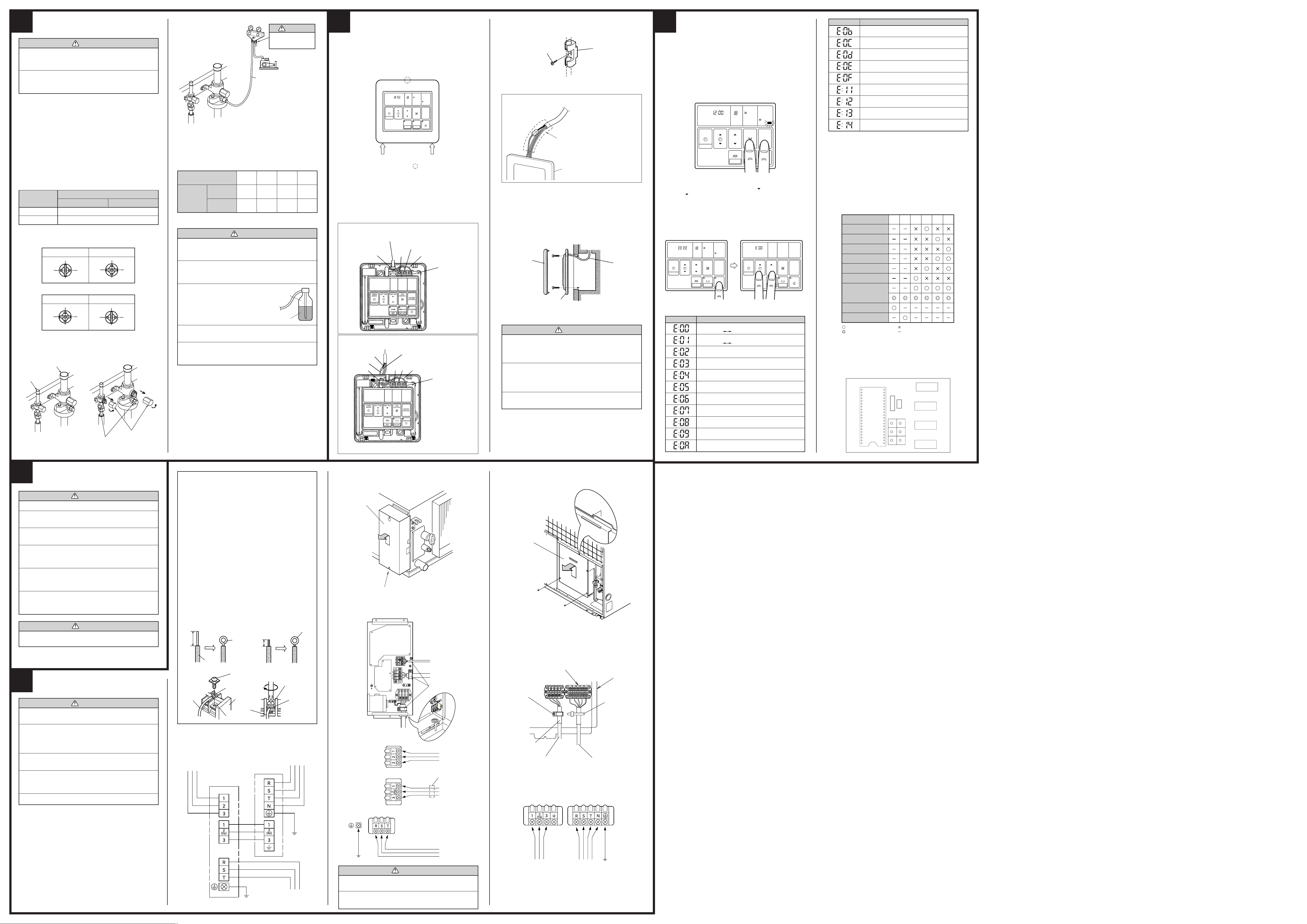
TEST RUNNING
1. REMOTE CONTROLLER
• Supply power to the crankcase heater 12 hours before the start of operation in the winter.
• For test running, when the remote controller FAN CONTROL button
and MASTER CONTROL button are pressed simultaneously for more
than three seconds when the air conditioner is not running, the air conditioner starts and TEST is displayed on the remote controller display.
However, the SET TEMP./DAY setting button does not function, but all
other buttons, displays, and protection functions operate (Fig. 44).
Fig. 44
CLOCK
NON STOP
21
TIMER
SET TIME TEMP./DAY FAN
MODE
CLOCK ADJUST
• When EE : EE blinks at the current time display, there is an error inside
the air conditioner. If the SET TIME button (
button ( ) are pressed simultaneously for more than three seconds,
the self diagnosis check will start and the error contents will be displayed at the current time display (Fig. 45). When the operation lamp
lights, press the START/STOP button and after operation lamp goes
off, perform the same operation (Fig. 45). Process the error contents by
referring to (Table 8).
Fig. 45
CLOCK
NON STOP
21
TIMER
MODE
CLOCK ADJUST
Stop operation.
Error cord Error contents
TEMP
°C
SET TIME TEMP./DAY FAN
CONTROL
SET
DAY OFF
Communication error
(indoor unit
Communication error
(indoor unit
Room temperature sensor open
Room temperature sensor shortcircuited
Indoor heat exchanger temperature sensor open
Indoor heat exchanger temperature sensor
shortcircuited
Outdoor heat exchanger temperature sensor open
Outdoor heat exchanger temperature sensor
shortcircuited
Power source connection error
Float switch operated
Outdoor temperature sensor open
AUTO
HIGH
DEFROST
MASTER
CONTROL
START/STOP
COOL
TEMP
°C
SET
Table 8
remote controller)
outdoor unit)
AUTO
HIGH
COOL
DEFROST TEST
CONTROL
MASTER
CONTROL
START/STOP
DAY OFF
) and SET TEMP./DAY
21
TIMER
SET TIME TEMP./DAY FAN
MODE
CLOCK ADJUST
AUTO
CONTROL
MASTER
CONTROL
SET
START/STOP
DAY OFF
Error cord Error contents
Outdoor temperature sensor shortcircuited
Discharge pipe temperature sensor open
Discharge pipe temperature sensor shortcircuited
Outdoor low pressure abnormal
Discharge pipe temperature abnormal
Model abnormal
Indoor fan abnormal
Outdoor signal abnormal
Outdoor EEPROM abnormal
• To stop test running, press the START/STOP button.
• For the operation method, refer to the operating manual and perform
operation check.
• Check that there are no abnormal sounds or vibration sounds during
test running.
2. OUTDOOR UNIT
When the outdoor temperature drops, the outdoor unit’s fans may switch
to low speed, or one of the fans may stop intermittently.
ERROR
The LED lamps operate as follows (Table 9) according to the error contents.
Table 9
Error contents LED1 LED2 LED3 LED4 LED5 LED6
Signal abnormal
Indoor unit abnormal
Discharge pipe
temperature abnormal
Outdoor heat exchanger
temperature abnormal
Outdoor temperature
abnormal
Power sorce connection
error
EEPROM abnormal
Outdoor high pressure
abnormal
Discharge pipe
temperature abnormal
: 0.5s ON/0.5s OFF (flash) : OFF
: 0.1s ON/0.1s OFF (flash) : Indefinite
When the fault is cleared, the LED lamp goes off.
However, for discharge pipe temperature abnormal and high pressure
abnormal, the LED lamp lights continuously for 24 hours, as long as the
power is not turned off.
Fig. 46 ERROR LED DISPLAY LAYOUT
CN14
TEST
IC 1
LED3
LED6
LED2
LED5
LED1
LED4
6
POWER
WARNING
1 The rated voltage of this product is 380-415 V 3ø 50 Hz.
2 Before turning on verify that the voltage is within the
342 to 457 V range.
3 Always use a special branch circuit and install a spe-
cial receptacle to supply power to the air conditioner.
4 Use a special branch circuit breaker and receptacle
matched to the capacity of the air conditioner.
(Install in accordance with standard.)
5 Perform wiring work in accordance with standards so
that the air conditioner can be operated safely and positively.
6 Install a leakage special branch circuit breaker in ac-
cordance with the related laws and regulations and electric company standards.
CAUTION
When the voltage is low and the air conditioner is difficult
to start, contact the power company the voltage raised.
7
ELECTRICAL WIRING
WARNING
1 Before starting work, check that power is not being sup-
plied to the indoor and outdoor unit.
HOW TO CONNECT WIRING
TO THE TERMINALS
A. For solid core wiring (or F-cable)
(1) Cut the wire end with a wire cutter or wire-cutting pliers, then strip
the insulation to about 25 mm (15/16”) to expose the solid wire.
(2) Using a screwdriver, remove the terminal screw(s) on the terminal
board.
(3) Using pliers, bend the solid wire to form a loop suitable for the
terminal screw.
(4) Shape the loop wire properly, place it on the terminal board and
tighten securely with the terminal screw using a screwdriver.
B. For strand wiring
(1) Cut the wire end with a wire cutter or wire-cutting pliers, then strip
the insulation to about 10 mm (3/8”) to expose the strand wiring.
(2) Using a screwdriver, remove the terminal screw(s) on the terminal
board.
(3) Using a round terminal fastener or pliers, securely clamp a round
terminal to each stripped wire end.
(4) Position the round terminal wire, and replace and tighten the ter-
minal screw using a screwdriver.
Fig. 36
A. Solid wire
Insulation
Strip 25 mm (15/16”)
Wire
Loop
Screw with
special washer
Round
terminal
Terminal
board
Wire
Terminal block
B. Strand wire
Strip 10 mm (3/8”)
Screw with
special washer
Round
terminal
Round
terminal
2. INDOOR UNIT SIDE
(1) Remove the control box cover and install each connection cord.
Fig. 38
Control box cover
Loosen the screws. (2 locations)
(2) After wiring is complete, clamp the remote controller cord, connection
cord and power supply cord with cord clamp.
(3) Attach the control box cover
Fig. 39
Remote controller cord
Connection cord
(To outdoor unit)
Cord clamp
3. OUTDOOR UNIT SIDE
(1) Remove the control box metal cover and install each connection cord.
Fig. 41
Control box metal cover
(2) After wiring is complete, clamp connection cord and power supply
cord with cord clamp.
(3) Attach the control box cover.
Fig. 42
Terminal board
Control box
metal
Cord clamp
Cable clip
2 Match the terminal board numbers and connection cord
colors with those of the outdoor unit.
Erroneous wiring may cause burning of the electric
parts.
3 Connect the connection cord firmly to the terminal
board. Imperfect installation may cause a fire.
4 Always fasten the outside covering of the connection
cord with the cord clamp. (If the insulator is chafed,
electric leakage may occur.)
5 Always connect the ground wire.
1. CONNECTIONS DIAGRAM
Fig. 37
Remote controller
Indoor unit
Red
White
Black
Ground
Outdoor unit
Power supply
3ø4W 380-415V
Ground
Power supply
3ø3W 380-415V
Power supply cord
Fig. 40
Red
Ground
White
Black
Remote controller
Connection cord
Outdoor unit
Power supply
CAUTION
1 Use care not to mistake the power supply and
connection wires when installing.
2 Install so that the wire for the remote controller will
not come in contact with other connection wires.
Insulation tube
Fig. 43
Connection cord
(indoor unit and outdoor
unit connection cord)
indoor unit
Power supply cord
Power supply
Ground
PART NO. 9365748039
 Loading...