

Generac 9798-2 Owner’s Manual
GEN RAC°I
Portable Products
Portable Generator Owner's Manual
Model No. 9798-2 (6,500Watt AC Generator) ManualNo. B2649 Revision 3 (06/01/200 I)
Visit our Generac website: www.generac-portables.com
_IL This is the safety alert symbol. It is used to alert you to potential personal injury hazards.
Obey allsafetymessagesthat follow this symbol to avoidpossibleinjury or death.
GeneracPortableProducts6500EXLExtendedLifeGenerator
EQUIPMENT
DESCRIPTION
This generator is an engine-driven, revolving field,
alternating current (AC) generator. It was designed to
supply electrical power for operating compatible electrical
lighting, appliance,tools and motor loads.This manual
contains informationfor a generator that operates
120and/or 240Volt, single phase,60 Hz devices that
require up to 6,500 watts (6.5 kW) of power that pull up
to 54.2Amps at 120Volts or 27.1Amps at 240Volts.
CAUTION! Do Not exceed the generator's
wattage/amperage capacity.The total load should not be
greater than 6,500 watts. See"Don't Overload the
Generator" on page I I.
The generator's revolvingfield is driven at about 3,600 rpm
by a single-cylinder engine.
Every effort has been madeto ensure that informationin
this manual is accurate and current However, Generac
reservesthe right to change,alter or otherwise improvethe
product and this document at any time without prior
notice.
SAFETY RULES
This generator set was designed and manufactured for
specific applications. Do Not attempt to modify the unit or
use it for anyapplication it was not designedfor. If you have
anyquestions about your generator's application, askyour
dealer or consult the factory.
The manufacturer could not possibly anticipate every
circumstance that might involvea hazard.For that reason
warnings in the manualand warnings on tags or decals
affixed to the unit are not all-inclusive. If you intendto
handle,operate or service the unit by a procedure or
method not specifically recommended by the manufacturer,
first make sure that such a procedure or method will not
render this equipment unsafeor pose a threat to you and
others.
Read this manual carefully and become familiar
with your generator set. Know its applications, its
limitations and any hazards involved.
_ AUTION! Do Not tamper with engine
The Emission Control System for this generator is
warranted for standards set by the Environmental
Protection Agency.For warranty informationrefer to the
engine owner's manual.
governed speed.High operating speeds are
dangerousand increaserisk of personal injuryor
damageto equipment.The generator supplies
correct rated frequency and voltage only when
running at proper governed speed.Incorrect
frequency and/or voltage can damagesome
connected electrical loads.Operating at excessively
low speedsimposesaheavy load.When adequate
engine power is not availableengine life may be
shortened.
_ ANGER! You must isolatethe generator from
the electric utility usingapproved transfer
equipment if this unit isused for backup power.
Failure to isolate the generator from the
power utility may result in injury or death to
electric utility workers and damage to the
generator due to a backfeed of electrical energy.
Whenever unit is providing backup power, the
electric utility must be notified.
_ DANGER! Generator exhaust gases contain
DEADLY carbon monoxide gas. If breathed in
sufficient concentrations, carbon monoxide
can cause unconsciousness or death. Operate
this equipment outdoors where adequate ventilation
isavailable.
/
2
Generac Portable Products 6500EXL Extended Life Generator
• The generator produces avery powerful voltage that can
cause serious injuryor death by electrocution. Never
touch bare wires or receptacles.Never permit a child or
any unqualified person to operate the generator.
• Never handleany kind of electrical cord or devicewhile
standing in water, while barefoot or while hands or feet
are wet Death or serious injury from electrocution may
result.
• Use aground fault circuit interrupter (GFCI) in any damp
or highly conductive area (such as metal decking or steel
work).
• Never useworn, bare,frayed or otherwise damaged
electrical cords with the generator. Death, serious injury
and property damagefrom electrical shock may result
• Gasoline is highly FLAMMABLE and its vapors are
EXPLOSIVE. Never allow smoking, open flames,
sparks or heat in the vicinity while handling
gasoline. Avoid spilling gasoline on a hot engine. Comply
with all laws regulating storage and handlingof gasoline.
• Do Not overfitl the fuel tank.Always allow room for fuel
expansion.If tank is overfllled, fuel can overflow
onto a hot engine and cause a FIRE or an
EXPLOSION.
• Never store a generator with fuel in the tank where
gasolinevapors might reach an open flame,spark or pilot
light (ason a furnace, water heater,clothes dryer). FIRE
or an EXPLOSION may result.
• The unit requires an adequateflow of cooling air for its
continued proper operation. Never operate the unit
inside anyroom or enclosure where the free flow of
cooling air into and out of the unit might be obstructed.
Allow at least2 feet of clearanceon all sidesof generator,
evenwhile operating unit outdoors, or you could damage
the unit
• Never start, or stop the unit with electrical loads
connected to receptacles with the connected devices
turned ON. Start the engine and let it stabilize before
connecting any electrical loads. Disconnect all electrical
loads before shutting down the generator.
• Do Not insert anyobject through cooling slots of the
engine.Youcould damagethe unit or injure yourself.
• Never operate the generator:
in rain; in any enclosed compartment; when connected
electrical devices overheat; if electrical output is lost; if
engine or generator sparks; if flame or smoke is observed
while unit is running; if unit vibrates excessively.
GROUNDING THE
G EN ERATO R
The National Electrical Code requires that the frame and
external electrically conductive parts of this generator be
properly connected to an approved earth ground. Local
electrical codes may also require proper grounding of the
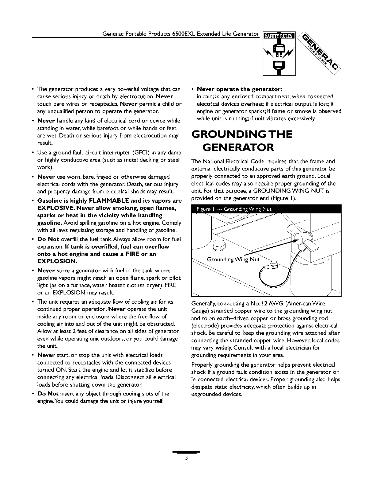
unit. For that purpose, a GROUNDING WING NUT is
provided on the generator end (Figure I).
Generally,connecting a No. 12AWG (American Wire
Gauge) stranded copper wire to the grounding wing nut
and to an earth-driven copper or brassgrounding rod
(electrode) provides adequateprotection againstelectrical
shock. Be careful to keep the grounding wire attached after
connecting the stranded copper wire. However, locat codes
may vary widely.Consult with a local electrician for
grounding requirements in your area.
Properly grounding the generator helps prevent electrical
shock ifa ground fault condition exists in the generator or
in connected electrical devices.Proper grounding also helps
dissipatestatic electricity, which often builds up in
ungrounded devices.
/
3
GeneracPortableProducts6500EXLExtendedLifeGenerator
Yourgeneratorrequiressomeassemblyandisreadyfor
useafterit hasbeenproperlyservicedwiththe
recommendedoilandfuel.
If you have any problems with the assembly of your
generator, please call the generator helpline at
1-800-270-1408.
IMPORTANT: Any attempt to run the unit before it has
been serviced with the recommended oil will result in an
engine failure.
REMOVE G EN ERATOR
FROM CARTON
• Set the carton on a rigid flat surfacewith "This Side Up"
arrows pointing upward.
• Carefully open the top flapsof the shippingcarton.
Review"Cold Weather Operation" on page 9.
• Cut down corners at one end of carton from top to
bottom and lay that side of carton down flat
• Removeall packingmaterial, carton fillers, etc.
• Removethe generator from the shipping carton.
INSTALLING TRAY AND
BATTERY
You must purchase and installa 12Volt DC battery (Series
U IL).The battery should be serviced with electrolyte fluid
and fully charged prior to installation.Install the battery as
follows:
• Find the battery tray andfasteners shipped loose in the
carton.
• Remove the four battery tray screwsfrom cradle.
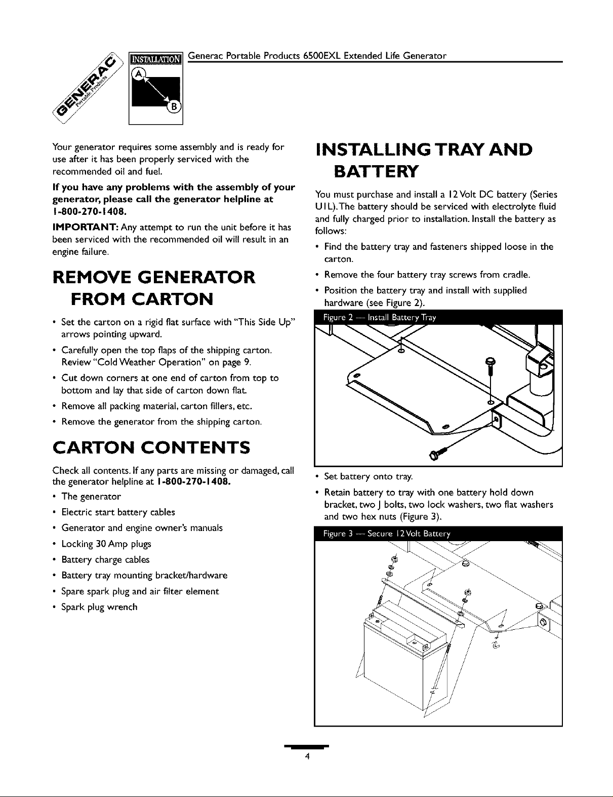
• Position the battery tray and installwith supplied
hardware (see Figure2).
CARTON CONTENTS
Check all contents. If any parts are missingor damaged,call
the generator helpline at 1-800-270-1408.
• The generator
Electric start battery cables
Generator and engine owner's manuals
Locking 30Amp plugs
Battery charge cables
Battery tray mounting bracket/hardware
Spare spark plug and air filter element
Spark plug wrench
• Set battery onto tray.
• Retain battery to tray with one battery hold down
bracket, two J bolts, two lock washers,two flat washers
and two hex nuts (Figure 3).
/
4
GeneracPortableProducts6500EXLExtendedLifeGenerator
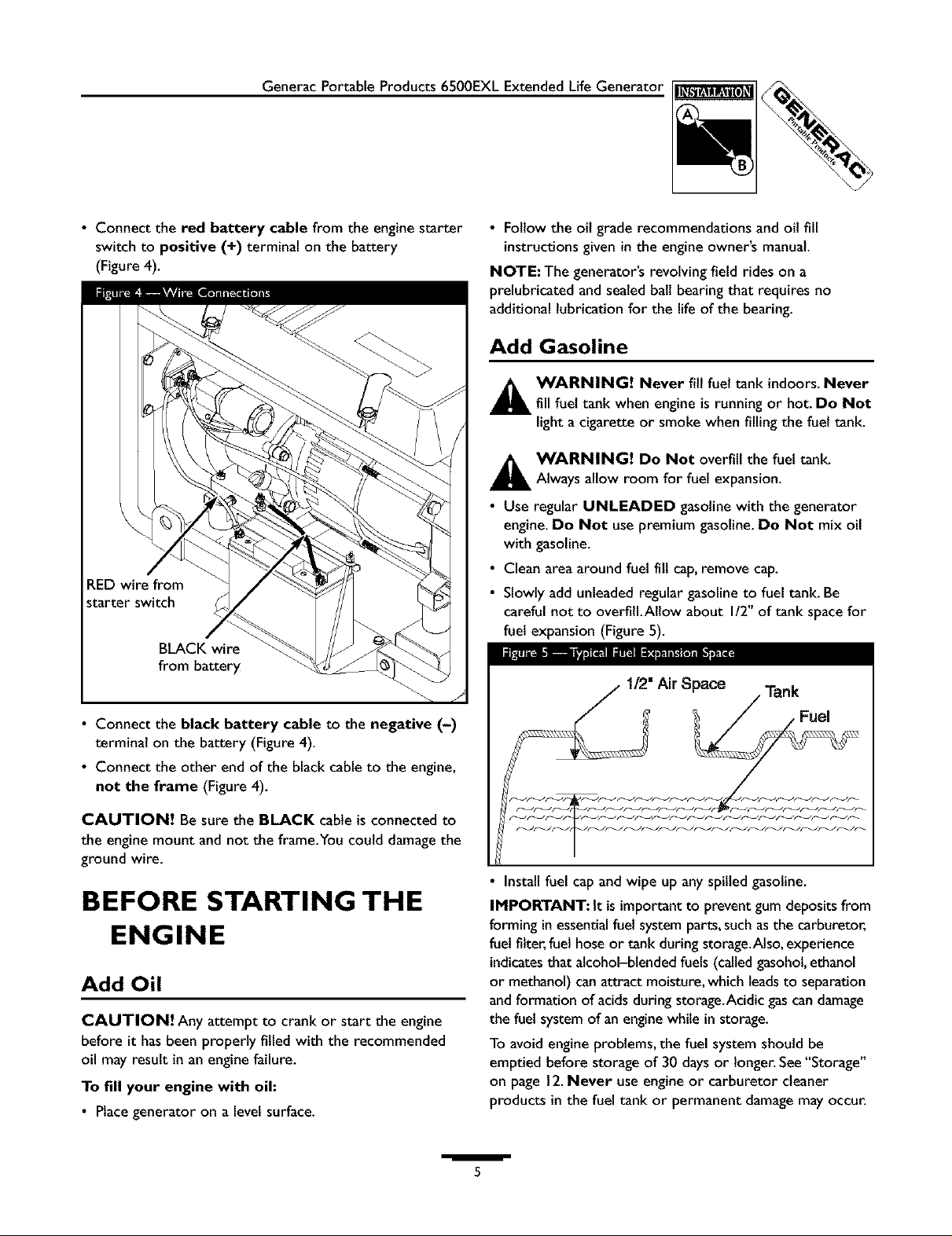
• Connect the red battery cable from the engine starter
switch to positive (+) terminal on the battery
(Figure 4).
RED wire from
starter switch
BLACK wire
from battery
• Follow the oil grade recommendations and oil fill
instructions given in the engine owner's manual.
NOTE:The generator's revolving field rides on a
prelubricated and sealedball bearing that requires no
additional lubrication for the life of the bearing.
Add Gasoline
A WARNING! Never fill fuel tank indoors. Never
fill fuel tank when engine is running or hot. Do Not
light a cigarette or smoke when filling the fuel tank.
A WARNING! Do Not overfill the fuel tank.
Always allow room for fuel expansion.
• Use regular UNLEADED gasoline with the generator
engine.Do Not use premium gasoline.Do Not mix oil
with gasoline.
• Clean area around fuel fill cap,remove cap.
• Slowly addunleaded regular gasolineto fuel tank. Be
careful not to overfill.Allow about I/2" of tank spacefor
fuel expansion (Figure 5).
1/2" Air Space Tank
• Connect the black battery cable to the negative (-)
terminal on the battery (Figure 4).
• Connect the other end of the blackcableto the engine,
not the frame (Figure4).
CAUTION! Be sure the BLACK cableisconnected to
the enginemount and not the frame.You could damage the
ground wire.
BEFORE STARTING THE
ENGINE
Add Oil
CAUTION! Any attempt to crank or start the engine
before it hasbeen properly filled with the recommended
oil may result in an engine failure.
To fill your engine with oil:
• Placegeneratoron alevel surface.
/
• Install fuel capand wipe up any spilled gasoline.
IMPORTANT: It is important to prevent gum depositsfrom
forming in essentialfuel system parts, suchasthe carburetor,
fuelfilter,fuel hoseor tank during storage.Also, experience
indicatesthat alcohol-blended fuels (calledgasohol,ethanol
or methanol) canattract moisture,which leadsto separation
andformation of acidsduring storage.Acidic gascan damage
the fuel systemof an enginewhile in storage.
To avoid engine problems, the fuel system should be
emptied before storage of 30 claysor longer. See"Storage"
on page 12.Never use engine or carburetor cleaner
products in the fuel tank or permanent damagemay occur.
5
GeneracPortableProducts6500EXLExtendedLifeGenerator
KNOWYOUR GENERATOR
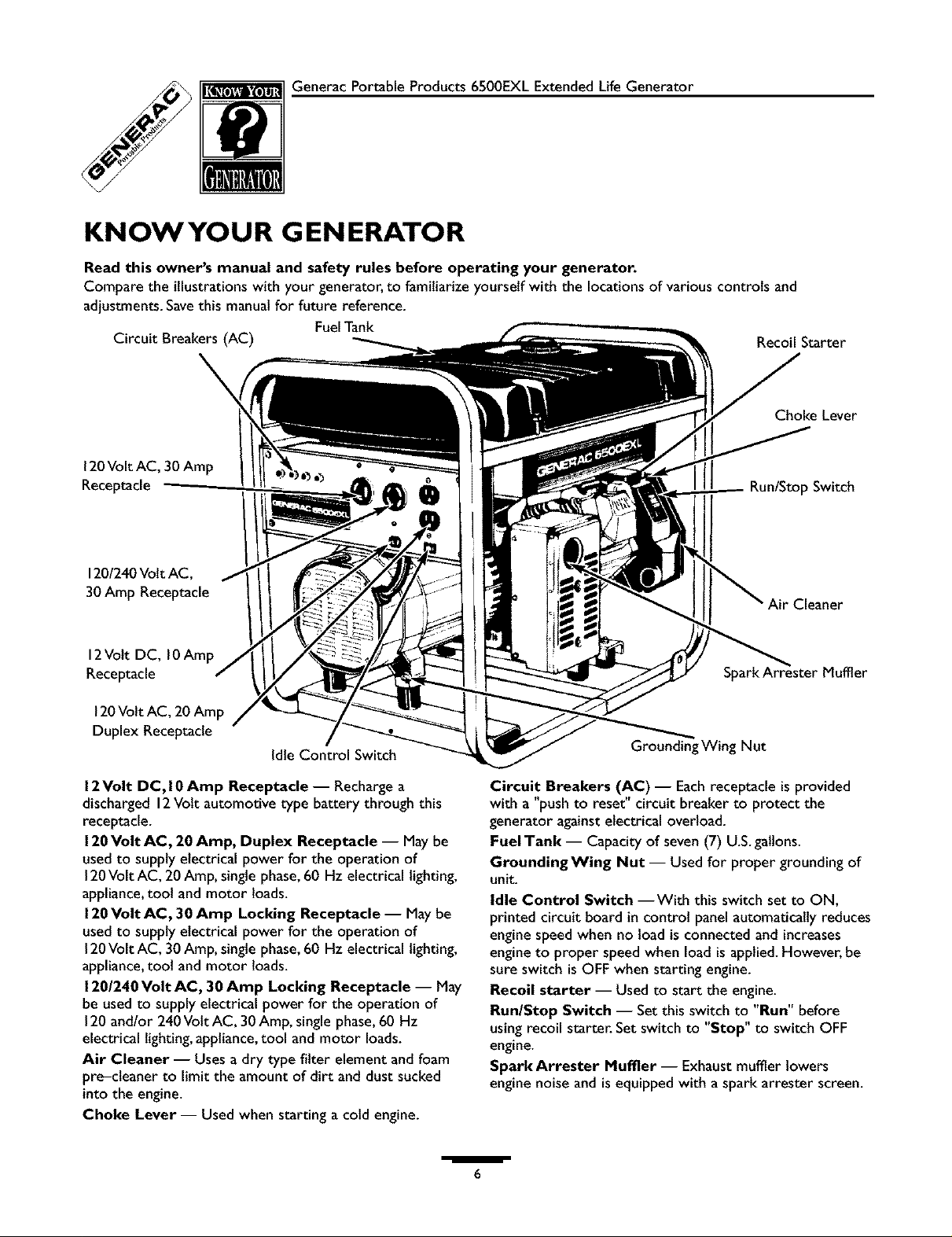
Read this owner's manual and safety rules before operating your generator.
Compare the illustrationswith your generator, to familiarize yourself with the locationsof variouscontrols and
adjustments.Savethis manualfor future reference.
Circuit Breakers (AC) Recoil Starter
120Volt AC, 30 Amp
Receptacle
FuelTank
Choke Lever
Run/Stop Switch
120/240Volt AC,
30 Amp Receptacle
12Volt DC, 10Amp
Receptacle
120Volt AC, 20 Amp
Duplex Receptacle
Idle Control Switch
12Volt DC, 10Amp Receptacle- Rechargea
discharged 12Volt automotive type battery through this
receptacle.
120Volt AC, 20 Amp, Duplex Receptacle -- May be
used to supply electrical power for the operation of
120Volt AC, 20 Amp,singlephase,60 Hz electrical lighting,
appliance,tool and motor loads.
120Volt AC, 30 Amp Locking Receptacle -- May be
usedto supply electrical power for the operation of
120Volt AC, 30 Amp,singlephase,60 Hz electrical lighting,
appliance,toot and motor loads.
120/240 Volt AC, 30 Amp Locking Receptacle -- May
be usedto supply electrical power for the operation of
120and/or 240Volt AC, 30Amp, singlephase,60 Hz
electrical lighting,appliance,tool and motor loads.
Air Cleaner -- Uses a dry type filter element and foam
pre-cteaner to limit the amount of dirt and dust sucked
into the engine.
Choke Lever -- Used when starting a cold engine.
Cleaner
Grounding Wing Nut
Circuit Breakers (AC) -- Eachreceptacle isprovided
with a "push to reset" circuit breaker to protect the
generator againstelectrical overload.
FuelTank -- Capacity of seven(7) U.S.gallons.
GroundingWing Nut -- Used for proper grounding of
unit.
Idle Control Switch --With this switch set to ON,
printed circuit board in control panel automatically reduces
engine speed when no load is connected and increases
engine to proper speed when load is applied. However, be
sure switch is OFF when starting engine.
Recoil starter -- Used to start the engine.
RunlStop Switch -- Set this switch to "Run" before
using recoil starter. Set switch to "Stop" to switch OFF
engine.
Spark Arrester Muffler -- Exhaust muffler lowers
engine noise and is equipped with a spark arrester screen.
/
6
 Loading...