

Page 1
Owner's Manual
". | =*=
Generator
Wheel kit
Storage Cover
Batter)" charge cables
Spare Spark Plug,Air Filter, and Oil Filter
Spark PlugWrench
Locking20 Amp plug
Locking30 Amp plug
Engineoil
Owner's manual
Enginemanual
If any parts are missing or damaged, call 1-800-270-1408.
Questions? Help is just a moment away!
Call:Generac Generator Helpline - 1-800-270-1408 M-F 8-5 CT
Web: www.generac-portables.com or www.briggsandstratton.com
SafetyRules.................................... 2-3
Assembly...................................... 4-5
Know Your Generator ............................. 6
Operation .................................... 7-I I
Product Specifications............................. 12
Maintenance.................................... 12
Storage........................................ 12
Troubleshooting ................................. 13
Schematic...................................... 14
Wiring Diagram ................................. 15
Replacement Parts............................. {6-19
Warranty ................................. Last Page
Page 2
EQUIPMENT
DESCRIPTION
Read this manual carefully and become familiar
with your generator. Know its applications, its
limitations and any hazards involved.
Thisgenerator is an engine-driven, revolving field, alternating
current (AC) generator.It was designed to supply electrical
power for operating compatible electrical lighting,appliances,
tools andmotor loads.Thegenerator's revolvingfield is
driven at about 3,600 rpm by a single-cylinderengine.
WARNING
The engine exhaust from this product contains I
chemicals known to the State of California to cause
cancer, b rth defects, or other reproduct ve harm.
DANGER
CAUTION! Do Not exceed the generator's
wattage/amperage capacity.See"Don't Overload the
Generator" on page I I.
Everyeffort hasbeenmade to ensurethat information inthis
manualisaccurateand current However,Generac reserves
the right to change,alter or otherwise improvethe product
and this document at anytime without prior notice.
The EmissionControl Systemfor this generator iswarranted
for standardsset by the Environmental Protection Agency.For
warranty informationrefer to the engineowner's manual.
SAFETY RULES
The safety alert symbol (_k) isusedwith a signalword
(DANGER, CAUTION,WARNING), a pictorial and/or a
safety messageto alert you to hazards.DANGER indicates
a hazardwhich, ifnot avoided,will result in death or serious
injury. WARNING indicatesa hazard which, if not avoided,
couldresult in death or serious injury.CAUTION
indicatesa hazardwhich, ifnot avoided,might result in
minor or moderate injury.CAUTION, when used
without the alert symbol, indicates a situation that could
result in equipment damage.Follow safety messagesto
avoid or reduce the risk of injury or death.
Operate generator ONLY outdoors.
Keep at least 2 feet of clearance on all sidesof generator for
adequateventilation.
Do not operate generator insideany building or enclosure,
includingthe generator compartment of a recreational vehicle
(RV).
DANGER
National ElectricCode requires generator to be properly
grounded to an approved earth ground. Call an electrician for
local grounding requirements.
DANGER
When usinggenerator for backup power, notify utility
company.Use approved transfer equipment to isolate
generator from electric utility.
Use aground fault circuit interrupter (GFCI) in any damp or
highly conductive area,such as metal decking or steel work.
Do not touch bare wires or receptacles.
Do not usegenerator with electrical cords which are worn,
frayed,bare or otherwise damaged.
Do not operate generator in the rain.
Do not handle generator or electrical cords while standing in
water, while barefoot, or while handsor feet are wet.
Do not allow unqualified persons or children to operate or
service generator.
Page 3
, WARNING
, WARNING
WHEN ADDING FUEL
Turn generator OFF and let it cool at least2 minutes before
removing gascap.Loosen cap slowly to relievepressure in tank_
Fill fuel tank outdoors.
Do not overfill tank.Allow spacefor fuel expansion.
Keepgasoline away from sparks,open flames, pilot lights, heat,
and other ignition sources.
Do not light a cigarette or smoke.
NHEN OPERATING EQUIPMENT
Do not tip engine or equipment at anglewhich causes
gasoline to spill.
tHEN TRANSPORTING OR REPAIRING EQUIPMENT
Transport/repair with fuel tank EMPTY or with fuel shutoff
valve OFE
Disconnect spark plug wire.
NHEN STORING GASOLINE OR EQUIPMENT WITH
FUEL IN TANK
Store awayfrom furnaces,stoves,water heaters, clothes
dryers or other appliancesthat have pilot light or other
ignition source becausethey can ignite gasoline vapors.
Do not touch hot surfaces.
Allow equipment to cool before touching.
CAUTION
Do not tamper with governed speed.Generator supplies
correct rated frequency and voltage when running at governed
speed.
Do not modify generator in any way.
CAUTION
See"Don't Overload Your Generator" on page I h
Start generator and let engine stabilize before connecting
electrical loads.
Connect electrical loads in OFF position, then turn ON for
operation.
Turn electrical loads OFF and disconnect from generator
before stopping generator.
DANGER
Do not allow any openflame, spark, heat, or lit cigarette
during andfor several minutes after charging a battery.
Wear protective goggles,rubber apron, and rubber gloves.
CAUTION
Use generator only for intended uses.
tf you have questions about intended use,askdealer or
contact Generac.
Operate generator only on level surfaces.
Do not expose generator to excessive moisture, dust, dirt, or
corrosive vapors.
Do not insert any objects through cooling slots.
tf connected devices overheat, turn them off and disconnect
them from generaton
Shut off generator if.'
-electrical output is lost;
-equipment sparks,smokes,or emits flames;
-unit vibrates excessively.
Page 4
Your generator requires some assemblyand is ready for
use after it has been properly serviced with the
recommended oil and fuel.
If you have any problems with the assembly of your
generator, please call the generator helpline at
1-800-270-1408.
IMPORTANT: Any attempt to run the unit before it has
been serviced with the recommended oil wilt result in an
engine failure.
REMOVE G EN ERATOR
FROM CARTON
• Set the carton on a rigid flat surface with "This SideUp"
arrows pointing upward.
• Carefully open the top flaps of the shipping carton.
Review"Cold Weather Operation" on page9.
• Cut down corners at one end of carton from top to
bottom and laythat side of carton down flat.
• Remove all packing material, carton fillers, etc.
• Remove the generator from the shipping carton.
INSTALL WHEEL KIT
To installthe wheel kit, the following tool is required:
• Socket wrench with I/2" or 13mmsockets.
• Needle-nose pliers.
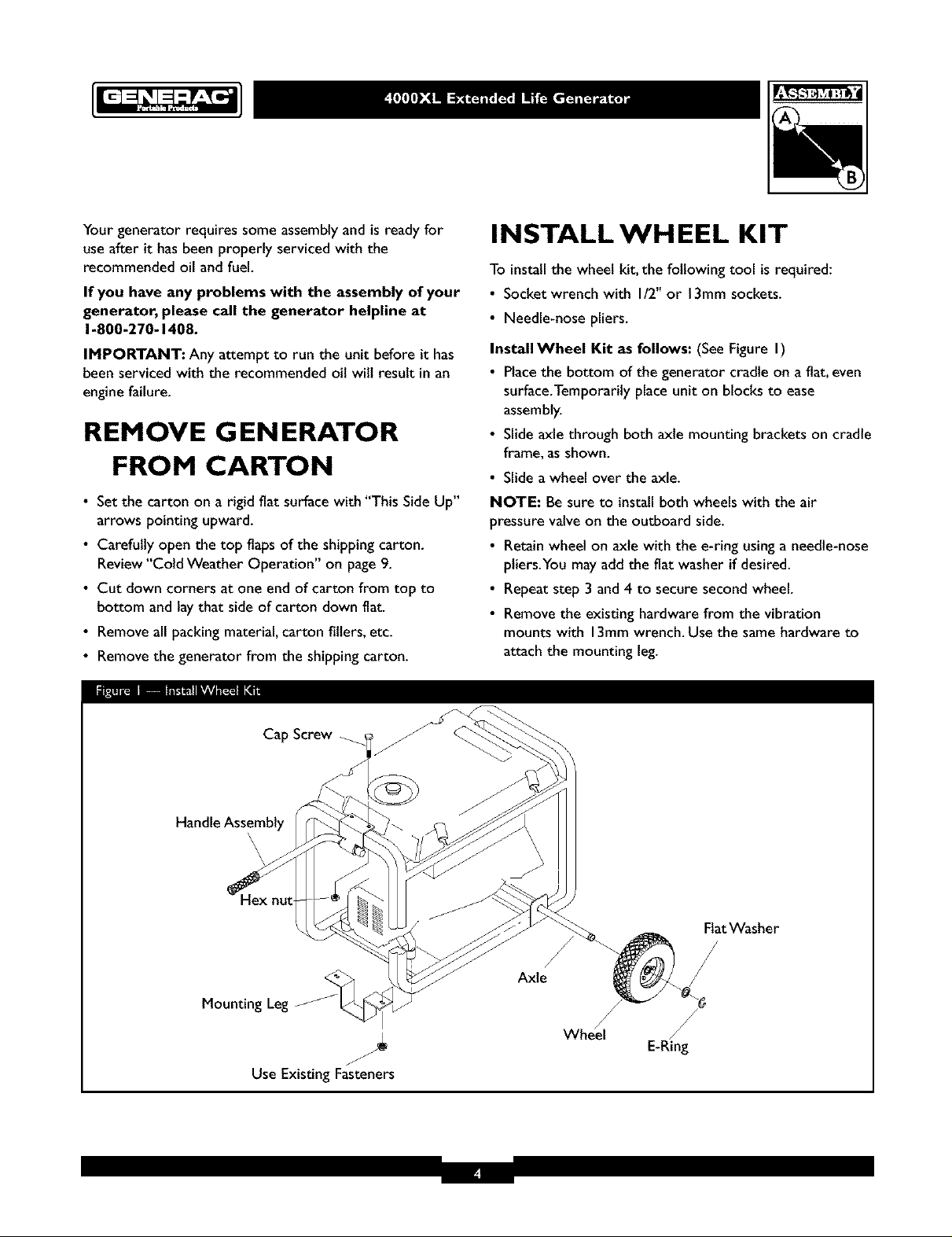
Install Wheel Kit as follows: (SeeFigure I)
• Placethe bottom of the generator cradle on a flat, even
surface.Temporarily place unit on blocks to ease
assembly.
• Slide axle through both axle mounting brackets on cradle
frame, as shown.
• Slide a wheel over the axle.
NOTE: Besure to installboth wheels with the air
pressure valve on the outboard side.
• Retain wheel on axle with the e-ring usinga needle-nose
pliers.You may add the fiat washer if desired.
• Repeat step 3 and 4 to secure second wheel.
• Remove the existing hardware from the vibration
mounts with 13mmwrench. Use the same hardware to
attach the mounting leg.
Cap Screw
Handle Assembly
\
\
\
Mounting Leg
Use Existing Fasteners
Axle
FlatWasher
/
/
E-Ring
Page 5
• Removethe temporary blocks.
• Center the handle bracket on generator frame at control
panel end of cradle.
• Attach handle bracket with two capscrews and two hex
nuts. Use two 13mm wrenches to tighten hardware.
• Check that all fasteners are tight andthe tires are
inflated between 15-40 PSI.
BEFORE STARTING THE
ENGINE
Add Oil
CAUTION! Any attempt to crank or start the engine
before it has been properly filled with the recommended
oil may result in an engine failure.
To fill your engine with oil:
• Place generator on a level surface.
• Follow the oil grade recommendations and oil fill
instructions given inthe engine owner's manual.
NOTE: The generator's revolving field rides on a
prelubricated and sealed ball bearing that requires no
additional lubrication for the life of the bearing.
Add Gasoline
_ ARNING! Never fill fuel tank indoors. Never
fill fuel tank when engine is running or hot.Allow
unit to cool for two minutes before refueling. Do
Not light a cigarette or smoke when filling the fuel
tank.
• Use regular UNLEADED gasolinewith the generator
engine.Do Not use premium gasoline. Do Not mix oil
with gasoline.
• Clean areaaround fuel fill cap,remove cap.
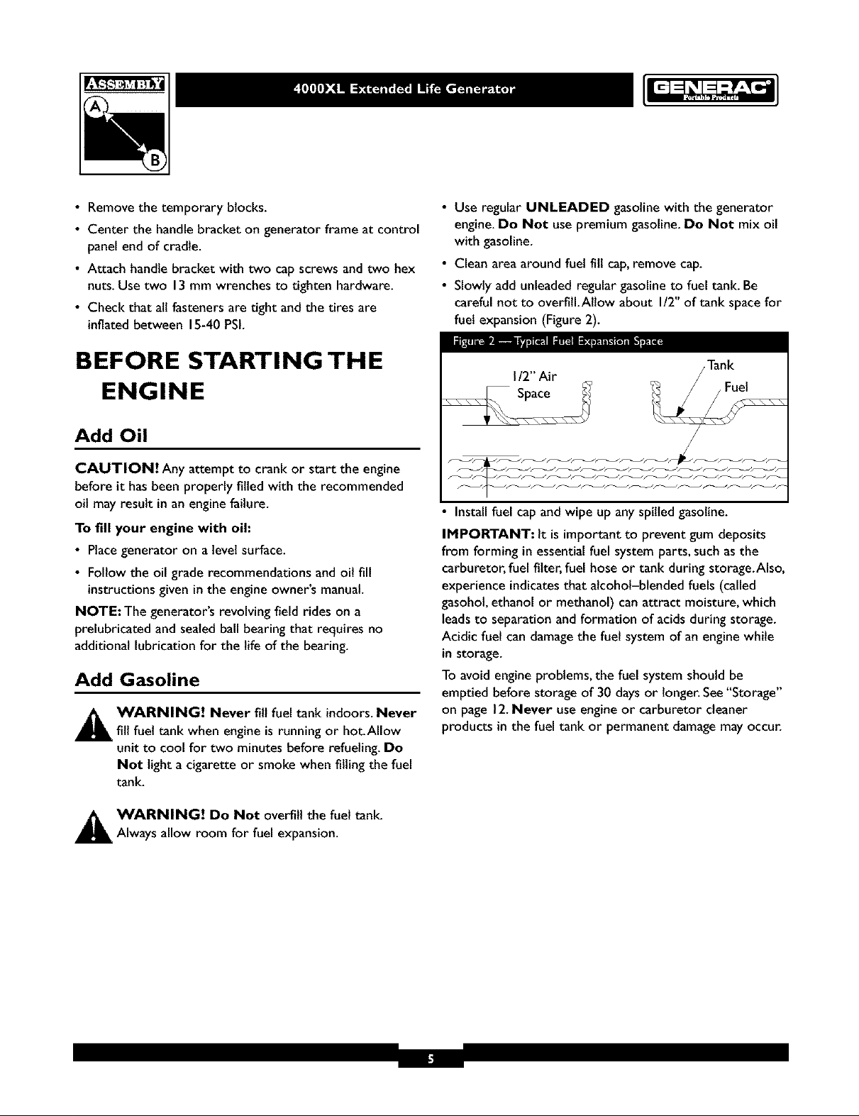
• Slowly add unleaded regular gasoline to fuel tank. Be
careful not to overfill.Allow about I/2" of tank spacefor
fuel expansion (Figure 2).
112" Air
Install fuel capand wipe up any spilled gasoline.
IMPORTANT: It is importantto prevent gum deposits
from forming in essentialfuel system parts,such asthe
carburetor,fuel filter,fuel hose or tank during storage.Also,
experience indicatesthat alcohol-blended fuels (called
gasohol,ethanol or methanol) canattract moisture, which
leadsto separation and formation of acids during storage.
Acidic fuel can damagethe fuel system of an enginewhile
in storage.
To avoid engine problems, the fuel system should be
emptied before storage of 30 daysor longer.See"Storage"
on page 12.Never useengine or carburetor cleaner
products in the fuel tank or permanent damagemay occur.
,_ WARNING! Do Not overfill the fuel tank.
Always allow room for fuel expansion.
Page 6
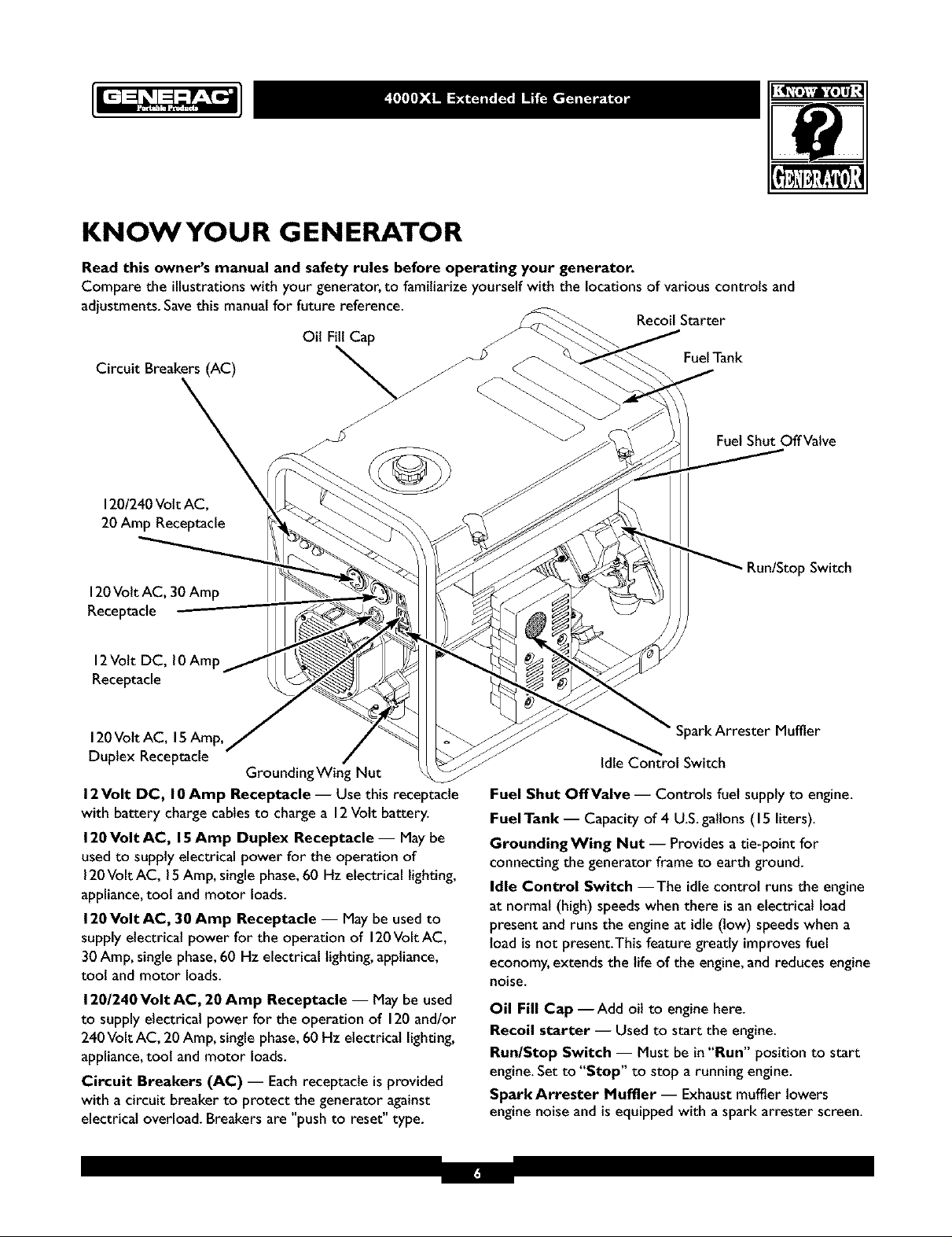
KNOWYOUR GENERATOR
Read this owner's manual and safety rules before operating your generator.
Compare the illustrations with your generator, to familiarize yourself with the locations of various controls and
adjustments. Save this manual for future reference.
Oil Fill Cap
Circuit Breakers (AC) _ _-
1201240Volt AC,
20 Amp Receptacle
120Volt AC, 30 Amp
Receptacle
12Volt DC, 10Amp
Receptacle
Recoil Starter
FuelTank
Fuel Shut Off Valve
Run/Stop Switch
120Volt AC, 15Amp,
Duplex Receptacle
GroundingWing Nut
12Volt OC, 10Amp Receptacle- Use this receptacle
with battery charge cables to charge a 12Volt battery.
120Volt AC, 15Amp Duplex Receptacle -- May be
usedto supply electrical power for the operation of
120Volt AC, 15Amp, single phase,60 Hz electrical lighting,
appliance,tool and motor loads.
120Volt AC, 30 Amp Receptacle -- Maybe used to
supply electrical power for the operation of 120Volt AC,
30 Amp, singlephase,60 Hz electrical lighting,appliance,
tool and motor loads.
12012.40Volt AC, 20 Amp Receptacle -- May be used
to supply electrical power for the operation of 120and/or
240 Volt AC, 20 Amp, single phase,60 Hz electrical lighting,
appliance,toot and motor loads.
Circuit Breakers (AC) -- Eachreceptacle isprovided
with a circuit breaker to protect the generator against
electrical overload. Breakers are "push to reset" type.
SparkArrester Muffler
Idle Control Switch
Fuel Shut OffValve -- Controls fuel supply to engine.
Fuel Tank -- Capacity of 4 U.S.gallons (15 liters).
GroundingWing Nut -- Provides a tie-point for
connecting the generator frame to earth ground.
Idle Control Switch --The idlecontrol runs the engine
at normal (high) speeds when there is an electrical load
present and runs the engine at idle (low) speedswhen a
load is not present.This feature greatly improves fuel
economy,extends the life of the engine,and reduces engine
noise.
Oil Fill Cap --Add oil to engine here.
Recoil starter -- Used to start the engine.
Run/Stop Switch -- Must be in "Run" position to start
engine. Set to "Stop" to stop a running engine.
Spare Arrester Muffler -- Exhaust muffler lowers
engine noise and is equipped with a spark arrester screen.
Page 7

GROUNDING THE
GENERATOR
The National Electrical Code requires that the frame and
external electrically conductive parts of this generator be
properly connected to an approved earth ground. Local
electrical codes mayalso require proper grounding of the
unit. For that purpose, a GROUNDING WING NUT is
provided on the generator end (Figure 3).
Wing Nut
I. Turn the fuel valve to the "On" position (Figure 4).
FuelValve is shown in
the "On" position
2.
Make sure the Idle Control switch is in"Off" position
(Figure 5).
I_I_'_L:I_ [eL_l _"_a
IDLE
Generally, connecting a No. 12AWG (American Wire
Gauge) stranded copper wire to the grounding wing nut
and to an earth-driven copper or brass grounding rod
(electrode) provides adequate protection against electrical
shock. Becareful to keepthe grounding wire attached after
connecting the stranded copper wire. However, local codes
may vary widely. Consult with a local electrician for
grounding requirements in your area.
Properly grounding the generator helps prevent electrical
shock if aground fault condition exists in the generator or
in connected electrical devices,especiallywhen the unit is
equipped with a wheel kit. Proper grounding also helps
dissipate static electricity, which often builds up in
ungrounded devices.
OPERATING THE
GENERATOR
_ CAUTION! Never start or stop unit withelectrical loads connected AND with the connected
devicesturned ON.
Starting the Engine
Disconnect all electrical loads from the generator. Follow
these start instruction steps in numerical order:
.
Setthe Run/Stop switch to "Run" position (Figure 6).
4.
Placethe choke lever in the "Full" choke position
(Figure7).
"Full" choke
Position
Page 8

S.
Grasp the recoil handle and pull slowly until slight
resistance is felt.Then pull rapidly one time only to
start engine.
• If engine starts, proceed to step 7.
• If engine fails to start, proceed to step 6.
6.
Move the choke lever to "Half" choke position, and
pull recoil handle twice.
• If engine fails to start, repeat steps 4 thru 6.
7. Move choke leverto "Run" position. If engine falters,
move choke leverto "Half" choke position until the
engine runs smoothly and then to "Run" position.
NOTE: If engine still fails to start after 3 pulls,check for
proper oll level in crankcase.This unit is equipped with a
Low Oit Shutdown System.Seeenginemanual.
Refer to the engine owner's manual for complete
starting instructions.
Connecting Electrical Loads
• Let engine stabilize and warm up for a few minutes after
starting.
• Plugin and turn on the desired 120and/or 240 VottAC,
single phase,60 Hz electrical loads.
• Do Not connect 240Volt loads to the 120Volt
receptacles.
• Do Not connect 3_hase loadsto the generator.
• Do Not connect 50 Hz loads to the generator.
• DO NOT OVERLOADTHE GENERATOR. See
"Don't Overload the Generator" on page I I.
Stopping the Engine
• Unplug all electrical loads from generator panel
receptacles.Never start or stop engine with electrical
devices plugged in and turned on.
• Put the idle control switch in the "Off" position.
• Let engine run at no-load for 30 secondsto stabilize the
internal temperatures of engine and alternator.
• Move run/stop switch to "Stop".
• Close the fuel shut-off valve.
switch off, the engine will run at the normal high engine
speed. Always have the switch off when starting and
stopping the engine.
Charging a Battery
A ARNING! Storagebatteries giveoff explosive
hydrogengas while recharging.An explosive mixture
will remain around the battery for a long time after
it has been charged.The slightest spark can ignite
the hydrogen and causean explosion, resulting in
blindnessor other serious injury.
A WARNING! Do Not permit smoking, open
flame,sparksor anyothersourceofheatarounda
battery.Wear protective goggles,rubber apron and
rubber gloves when working around a battery.
Battery electrolyte fluidis an extremely caustic
sulfuric acid solution that can causesevere burns. If
spill occurs flush areawith clear water immediately.
Your generator has the capability of recharging a discharged
12Volt automotive or utility style storage battery. Do Not
usethe unit to charge any6Volt batteries. Do Not use the
unit to crank an enginehaving a discharged battery.
To recharge 12Volt batteries, proceed as follows:
• Check fluidlevel in all battery cells. If necessary,add
ONLY distilled water to cover separators in battery cells.
Do Not use tap water.
• If the battery isequipped with vent caps,make sure they
are installed and are tight.
• If necessary,clean battery terminals.
• Connect battery charge cable connector plug to panel
receptacle identified by the words "12-VOLTS D.C".
• Connect battery charge cable clamp with red handle to
the positive (+) battery terminal (Figure8).
12VOLT D.C.
RECEPTACLE
Operating Automatic Idle Control
This switch isdesignedto greatly improve fuel economy.
When this switch is turned ON, the engine will only
run at its normal high governed engine speed when an
electrical load is connected.When an electrical load is
removed,the enginewill run at a reduced speed.With the
+
POS NEG
12VOLTBAl-I'ERY
I:|
Page 9

• Connect battery chargecableclamp with black handle
to the negative (-) battery terminal (Figure8).
• Start engine. Let the engine run while battery recharges.
• When battery hascharged,shut down engine
NOTE: Use an automotive hydrometer to test battery
state of charge and condition. Follow the hydrometer
manufacturer's instructions carefully.Generally,a battery is
considered to be at 100%state of chargewhen specific
gravity of its fluid (asmeasuredby hydrometer) is 1.260 or
higher.
COLD WEATH ER
OPERATION
Under certain weather conditions (temperaturesbelow
40°F [4°C] and a high dew point),your generator may
experience icingof the carburetor and/or the crankcase
breather system.
In an emergency,use the original shipping box asa
temporary shelter:
• Cut off all flaps.
• Cut out one of the longsidesof the box to expose
exhaust side of unit.Ensurea minimum of two feet
clearance between open side of box and nearest object.
• Cut appropriate slots to accessreceptacles of unit.
• Start unit, then place box over it.
IMPORTANT: Remove shelter when temperature is
above 40°F [4°C].
For a more permanent shelter,build a structure that will
enclose three sides and the top of the generator:
• Make sure entire muffler-side of generator is exposed.
Note that your generator may appear different from that
shown in Figure 9.
• Ensure a minimum of two feet clearance between open
side of box and nearest object.
• Face exposed end away from wind and elements.
• Enclosure should hold enough heat created by the
generator to prevent problems.
A CAUTION! Never run unit indoors.Do Not
enclose generator any more than shown.
RECEPTACLES
120 Volt AC, 15 Amp Receptacles
Eachof these outlets is protected againstoverload by
15Amp push-to-reset type circuit breakers (Figure 10).
Use each outlet to operate 120Volt, 60 Hz,single phase
loads requiring 1,800(I.8 kW) watts at 15Amps of current.
Page 10

120/240 Volt AC, 20 Amp Locking
Receptacle
Use a NEMA LI4-20 plug with this receptacle. Connect a
4-wire cord set rated for 250Volts at 20 Amps (or greater)
(Figure I I).You canuse the same4-wire cord if you plan to
run a 120Volt load.
4-Wire Cord Set
I
120 Volt AC, 30 Amp Locking
Receptacle
Use a NEMA L5-30 plug with this receptacle.Connect a
3-wire cord set rated for 125Volts AC at 30 Amps to the
plug (Figure 12).
pa_ Ip,(*]kv_aJr.,T *" . * :" ._ m
3-Wire Cord Set
i NEMA L5-30
Neutral
120V
' (Neutral)
Y (Hot) X (Hot)
NEMA L14-20
This receptacle powers 120/240Volt AC, 60 Hz,single
phaseloadsrequiring up to 2,400 watts of power at
20 Amps for 120Volts;4,000 watts of power (4.0 kW) at
16.7Amps for 240Volts.The outlet is protected by a
20 Amp push-to-reset circuit breaker.
_L CAUTION! Although this outlet israted for
240Volt 20Amp (up to 4,800 watts), the generator
is only rated for 4,000 watts. Powering loadsthat
exceed the wattage/amperage capacity of the
generator can damageit or causeserious injuries.
240 Volt loads powered through this outlet should
not exceed 16.7Amps of current draw.
Ground (Green)
Hot
Ground (Green)
Use this receptacle to operate 120Volt AC, 60 Hz, single
phaseloadsrequiring up to 3,600 watts (3.6 kW) of power
at 30Amps.The outlet is protected by a 30Amp
push-to-reset circuit breaker.
12 Volt DC, I 0 Amp Receptacle
This connector (identified by the legend"I2-VOLT D.C")
supplies 12Volts DC at I0Amps through battery charging
cablesfor recharging 12Volt batteries (Figure 13).See
"Charging a Battery" on page 8.
IIII Ip,iV_II[IIDI*ql[9]_ll; _tq
Page 11

DON'T OVERLOAD YOU R
GENERATOR
Capacity
You must make sure your generator can supply enough
rated (running) and surge (starting) watts for the items you
wilt power at the same time. Follow these simple steps:
I. Select the items you will power at the same time.
2. Total the rated (running) watts of these items.Thisis
the amount of power your generator must produce to
keep your items running.SeeFigure 14.
3. Estimate how many surge (starting) watts you will
need.Surge wattage isthe short burst of power
needed to start electric motor-driven tools or
appliancessuch asa circular saw or refrigerator.
Becausenot all motors start at the same time, total
surge watts can be estimated by adding only the
item(s) with the highest additional surge watts to the
total rated watts from step 2.
Example:
Tool or Appliance
Window Air
Conditioner
Refrigerator
Deep Freezer
Television
Light (75 Watts)
Total Rated (Running)Watts = 3075
Highest Additional SurgeWatts = 1800
Total Generator Output Required = 4875
Rated (Running)
Watts
1200
800
50O
500
75
3075 Total
Running Watts
Power Management
To prolong the life of your generator and attached devices,
it is important to take care when addingelectrical loads to
your generator.There should be nothing connected to the
generator outlets before starting it's engine.The correct
and safeway to managegenerator power is to sequentially
add loads as follows:
I. With nothingconnected to the generator, start the
engine asdescribed in this manual.
2. Plugin and turn on the first load,preferably the largest
load you have.
3. Permit the generator output to stabilize (engine runs
smoothly and attached device operates properly.
Additional Surge
(Starting)Watts
1800
1600
5O0
1800 Highest
SurgeWatts
4. Plug in and turn on the next load.
5. Again, permit the generator to stabilize.
6. Repeat steps 4 and 5for each additional load.
Never add more loadsthan the generator capacity.Take
specialcare to consider surgeloads in generator capacity,
asdescribed above.
Rated*
Tool or Appliance
Essentials
LightBulb - 75 watt
Deep Freezer
SumpPump
Refrigerator/Freezer - 18Cu. Ft.
Water Well Pump- I/3 HP
Heating/Cooling
Window AC - 10,000BTU
Window Fan
FurnaceFanBlower - I/2 HP
Kitchen
Microwave Oven - 1000Watt
Coffee Maker
Electric Stove - SingleElement
Hot Plate
Family Room
DVD/CD Player
VCR
Stereo Receiver
Color Television - 27"
Personal Computer w/I 7" monitor
Other
Security System
AM/FM Clock Radio
GarageDoor Opener - I/2 HP
Electric Water Heater - 40 Gallon
DIY/Job Site
Quartz Halogen Work Light
Airless Sprayer - I/3 HP
Reciprocatin_ Saw
Electric Drill - I/2 HP
Circular Saw - 7 I/4"
Miter Saw - I0"
Planer/Jointer - 6"
Table Saw/RadialArm Saw - I0"
Air Compressor - I-I/2 HP
*Wattages listed are approximate only. Check toot or
appliance for actual wattage.
(Running)
Watts
75
500
8O0
8O0
1000
12O0
3OO
8O0
1000
1500
1500
25O0
100
100
450
5o0
8o0
18o
3O0
480 520
40O0
1000
600 1200
960 960
1000 1000
1500 1500
1800 1800
1800 1800
2000 2000
2500 2500
Additional
Surge
(Starting)
Watts
500
1200
1600
20O0
1800
6O0
1300
Page 12

SPECIFICATIONS
Maximum SurgeWatts ................. 6,600 watts
Continuous Wattage Capacity ........... 4,000 watts
Power Factor .............................. 1.0
Rated Maximum Continuous AC Load Current:
At 120Volts ....................... 33.3Amps
At 240 Volts ....................... 16.7Amps
Phase................................. I-phase
Rated Frequency ....................... 60 Hertz
FuelTank Capacity................... 4 U.S.gallons
ShippingWeight ......................... 134 Ibs.
GENERAL MAINTENANCE
RECOMMENDATIONS
The Owner/Operator is responsible for making sure that
all periodic maintenance tasks are completed on a timely
basis;that all discrepanciesare corrected; and that the unit
is kept clean and properly stored. Never operate a
damaged or defective generator.
Engine Maintenance
Seeengine owner's manualfor instructions.
contact with used motor oil. Used motor oil has
_ AUTION! Avoid prolonged or repeated skin
been shown to cause skin cancer in certain
laboratory animals.Thoroughly wash exposed areas
with soap and water.
KEEPOUT OF REACH OF CHILDREN. DON'T
POLLUTE.CONSERVE RESOURCES.RETURN
USED OILTO COLLECTION CENTERS.
Generator Maintenance
Generator maintenanceconsists of keeping the unit clean
and dry. Operate and store the unit in a clean dry
environment where it will not be exposed to excessive
dust, dirt, moisture or any corrosive vapors.Cooling air
slots in the generator must not become clogged with
snow, leavesor anyother foreign material.
NOTE: Do Not use a garden hoseto clean generator.
Water can enter engine fuel system and causeproblems. In
addition, if water enters generator through cooling air slots,
some of the water will be retained in voids andcracks of
the rotor and stator winding insulation.Water and dirt
buildup on the generator internal windings will eventually
decreasethe insulation resistanceof these windings.
To Clean the Generator
• Use a damp cloth to wipe exterior surfaces clean.
• A soft bristle brush may be used to loosen caked on dirt
or oil.
• A vacuum cleaner may be used to pick up loose dirt and
debris.
• Low pressure air (not to exceed 25 psi) maybe used to
blow awaydirt. Inspect cooling air slots and opening on
generator.These openings must be kept clean and
unobstructed.
STO RAG E
The generator should be started at least once every seven
claysandallowed to run at least 30 minutes. If this cannot
be done and you must store the unit for more than
30 days,use the following guidelines to prepare it for
storage.
Generator Storage
• Clean the generator asoutlined in"ToClean the
Generator"
• Check that cooling air slots and openings on generator
are open and unobstructed.
_ CAUTION! Storage covers can be flammable.
Do Not place a storage cover over a hot
generator. Let the unit coot for a sufficient time
before placing the cover on the unit.
Engine Storage
See engine owner's manualfor instructions.
Other Storage Tips
• To prevent gum from forming in fuel system or on
essential carburetor parts, add fuel stabilizer into fuel
tank and fill with fresh gasoline. Run the unit for several
minutes to circulate the additive through the carburetor.
The unit and fuel can then be stored for up to
24 months. Fuel stabilizer can be purchased locally.
• Do Not store gasoline from one season to another
unless it has been treated as described above.
• Replace fuel container if it starts to rust. Rust and/or dirt
in fuel can cause problems if it's used with this unit.
• Store in clean and dry area.
Page 13

TROUBLESHOOTING
Problem
Cause
I. Circuit breaker isopen.
Engine is running, but
no AC output is
available.
Engine runs good but
bogs clown when loads
are connected.
2. Poor connection or defective cord set.
3. Connected device isbad.
4. Fault in generator.
I. Short circuit in a connected load.
2. Generator is overloaded.
3. Enginespeed istoo slow.
4. Shorted generator circuit.
4. Contact Generac service facility.
4. Contact Generac service facility.
I. Run/Stopswitch set to "Stop".
2. Dirty air cleaner.
3. Out of gasoline.
4. Stalegasoline.
4. Drain gastank and fill with fresh fuel.
5. Spark plug wire not connected to spark
plug.
6. Badspark plug.
Engine will not start; or
starts and runs rough.
7. Water in gasoline.
8. Overchoking.
8.
9. Low oil level.
10. Excessivelyrich fuel mixture.
I I. Intake valve stuck open or closed.
12. Enginehaslostcompression. 12.
I. Out of gasoline. I.
Engine shuts down 2. Low oil level. 2.
during operation. 3. Fault in engine. 3.
I. Loadistoo high. I.
Engine lacks power. 2. Dirty air filter. 2.
3. Engineneeds to be serviced. 3.
I. Choke isopened too soon. I.
Engine "hunts" or
falters. 2.
2. Carburetor isrunning too rich or too
lean.
Solution
I. Resetcircuit breaker.
2. Check and repair.
3. Connect another device that is ingood
condition.
I. Disconnect shorted electrical load.
2. See"Don't Overload the Generator"
on page I I.
3. Contact Generac Power Systems
servicefacility.
I. Setswitch to "Run".
2. Clean or replace air cleaner.
3. Fill fuel tank.
5. Connect wire to spark plug.
6.
Replacespark plug.
7.
Drain gastank; fill with fresh fuel.
Put choke lever to "Run" position.
9.
Fill crankcaseto proper level.
10.
Contact Generac Power Systems
servicefacility.
II.
Contact Generac Power Systems
servicefacility.
Contact Generac Power Systems
servicefacility.
Fillfuel tank.
Fill crankcaseto proper level.
Contact Generac Power Systems
servicefacility.
See"Don't Overload the Generator"
on page I I.
Replaceair filter.
Contact Generac Power Systems
servicefacility.
Move choke to halfway position till
engine runs smoothly.
Contact Generac Power Systems
servicefacility.
Page 14

SCHEMATIC
PO/_ER POWER
mH O'('d
>X
O/('d LO_
R
m H
D •
S D
G
A
E
S
O
N
A
SPARK
PLUG
ENG
IGNITION
BATTERY CHARGE
BRN BLK BRN
66 55 77
RED BLK
AUTO 13 55
3
o/
RED
Page 15

WIRING DIAGRAM
BLO
11
]FEEDBACK \
BATTERY
CHARGE
RECTIFIER
\
GATE
SIGNAL
pq
GRN
3 PIN
NUT ON ENGINE BLOCK
LOW OIL
PRE££URE
SWITCH
ENGINE CATHODE
RUN
SWITCH
LOW OIL
PRESSURE
LED
Page 16

EXPLODEDVIEW- MAIN UNIT
57
45 \
58
8
\
47 _
5
\
1 --t _t!
¢'
J_
J
SEE
DETAIL " Y
10
\
\
\
6
3O
23
14
/
16
DETAIL " Y "
@
24
\
59
61
\
65
62
.?
\
65
89
67
66
7o
Page 17

_r3
PARTS LIST- MAIN UNIT
Item Part # Qty
I A93199GS
2 A84021GS
3 NSP
4 66365GS
5 84141JGS
6 83540JGS
7 65791GS
8 96796GS
9 73054GS
10 86307GS 4
II 47480GS I
12 84508GS 2
13 B2153GS 4
14 83208GS I
15 B4986GS I
16 66476GS 2
17 89476GS I
18 70644GS I
19 84346GS 3
20 40976GS 2
21 83083GS I
22 83071GS I
23 81917GS I
24 77816GS I
25 SRV66825DGS I
26 85652GS 2
27 67989GS l0
28 20566GS I
29 84409GS I
30 74908GS 4
31 87116GS I
32 86308GS 4
33 65795GS I
34 66849AGS I
35 67022GS 2
36 84132GS I
Description
CRADLE
SUPPORT,Engine
ENGINE
HOUSING, EngineAdapter
ASSY,Rotor (Inctds Item 7)
ASSY,Stator
BEARING
WASHER
DECAL, Fuel Shut Off
SCREW
SCREW
MOUNT, Vibe
SCREW
BRACKET,Muffler
DECAL, Ground
SCREW
GASKET,Exhaust
SCREW
SCREW
SCREW
SCREEN,SparkArrest
MUFFLER
PIN,Roll
DECAL, Caution Hot Muffler
CARRIER,Rear Bearing
MOUNT, Vibe
NUT
DECAL, 1-800
SLEEVING,Flexo
SCREW
ASSY,Control Panel(see page 18)
BOLT
RECTIFIER,Battery Charge
SCREW
GROMMET,Rubber
ASSY,Drive Module Pwr Reg.
Item Part # Qty Description
37 66386GS I ASSY,Brush Holder
38 66849GS 2 SCREW
39 B4871GS I COVER, Bearing Carrier
40 189404GS 2 DECAL, Heat Shield
41 86494GS I SCREW,Wing
42 86292GS I SCREW
43 77395GS 4 NUT, Lock
44 83465GS 4 GROMMET,Tank
45 93826GS I DECAL, Operating Instructions
46 78831BGS 4 SCREW
47 80270GS VALVE,Tank
48 78299GS BUSHING, PtasticTank
49 85134GS GUAGE, Fuel
50 88325GS ASSY,Tank,Fuel
(IncludesItems 47 & 48)
51 J84042GS SHIELD,Heat
52 84687GS INSULATION
53 85000GS CLIP,Insulation
54 14353621GS WIRE, Ground
55 23762GS WASHER
56 26850GS 2 WASHER
57 92982GS DECAL, Danger
58 189405GS DECAL, Control Panel
59 BB3061GS BOTTLE,Oil
60 43483GS PLUG,250V 20 A 4-Prong
61 37806GS PLUG, 125V 30A 3-Prong
62 70185GS FILTER,Oil
63 78601GS CLEANER,Air
64 65787GS CABLE,Battery Charge
65 189383GS MANUAL, Owners
66 A8926GS MANUAL, Engine
67 84882GS WRENCH, Spark Plug
69 72347GS PLUG,Spark
70 84895GS COVER, Storage
Optional Accessories Not Included:
84883GS Cord Wrap
Page 18

_r3
EXPLODED VIEW AND PARTS LIST - CONTROL PANEL
14
2
f
1
'\ 7
\
\
\
\
8
18
17 F 24
19 \
12_
25.
Item Part # Qty
I 83976GS I
2 83975GS I
3 66818GS 2
4 66821GS
5 68867CGS
6 68868CGS
7 75207AGS
8 75207GGS 2
9 82538GS I
10 84134GS I
II 83514GS I
12 83970GS I
17
26
24 4
10
\ _ 9
\ 16 3
13
Description Item Part # Qty Description
PANEL,Control 13 84028GS I TRANSFORMER,Idle Control
BOX, Control 14 67022GS I GROMMET, Rubber
OUTLET, 120VAC, 15A Duplex 15 85584GS I BAR, Bus
OUTLET, 12V DC 16 84543AGS 2 SCREW
OUTLET, 120/240VAC, 20A 17 84543CGS 9 SCREW
Locking 18 84198GS 3 SHIELD,Circuit Breaker
OUTLET, 120VAC, 30A 19 84197GS I BAR, Circuit Breaker Retaining
Locking 21 75476GS 2 SCREW
BREAKER,Circuit 22 22264GS 4 WASHER,Lock
BREAKER,Circuit 23 51715GS 4 NUT
SWITCH, On/Off Rocker 24 84543BGS l0 SCREW
GROMMET,Rubber 25 84335GS I HARNESS,Wire
BREAKER,Circuit 26 82542GS I BAR, DC Outlet Retaining
CONTROL BOARD,System
Page 19

_rs
EXPLODED VIEWAND PARTS LIST-WHEEL KIT
'\
\
\
\
\
8
/
J
USE EXISTING FASTENERS
TB SECURE ITEM #2
Item Part # Qty Description
I 189715GS I ASSY,Handle
2 BI764GS I LEG,Mounting
3 52858GS 2 NUT, Locking
4 39287GS 2 SCREW
5 191267FGS I AXLE
6 B4966GS 2 WHEEL
7 191265GS 2 E-RING
8 22247GS 2 WASHER
/
_c
6
Page 20

LIMITED WARRANTY
GENERAC PORTABLE PRODUCTS OWNERWARRANTY POLICY Effective October I, 2001
LIMITED WARRANTY
"Generac Portable Products,LLC will repair or replace,free of charge,any part, or parts of the equipment that are defectivein material or
workmanship or both.Transportation charges on parts submitted for repair or replacement under this Warranty must be borne by purchaser.
This warranty is effective for the time periods and subject to the conditions provided for in this policy. For warranty service, find the nearest
Authorized Service Dealer in our dealer Iocator map at www.generac-portables.com or call 1-877-544-0982.THERE ISNO OTHER EXPRESS
WARRANT'_I IMPLIEDWARRANTIES, INCLUDING THOSE OF MERCHANTABILITY AND FITNESSFORA PARTICULAR PURPOSE,ARE
LIMITED TO THE TIME PERIOD SPECIFIED,OR TO THE EXTENT PERMITTED BY LAW ANY AND ALL IMPLIEDWARRANTIES ARE
EXCLUDED. LIABILITY FOR CONSEQUENTIAL DAMAGES UNDER ANY AND ALL WARRANTIES ARE EXCLUDED TO THE EXTENT
EXCLUSION IS PERMITTED BY LAW. Some states do not allow limitationson how long an impliedwarranty lasts,and some states do not
allow the exclusion or limitationof incidental or consequential damages,so the above limitation and exclusion may not apply to you.This
warranty gives you specific legal rights and you mayalso have other rights which vary from state to state and country to country."
WARRANTY PERIOD*
PRODUCTS**
Portable Generator
SideValve EnginePowered)
Portable Generator
(Overhead Valve EnginePowered)
Electric Powered PressureWasher
Gasoline Powered PressureWasher
*The warranty period beginson the date of purchaseby the first retail consumer or commercial end user,and continues for the period of time
stated in the table above. "Consumer use" meanspersonal residential household use by a retail consumer. "Commercialuse" means all other uses,
includingusefor commercial, income producing or rental purposes. Once equipment hasbeen used commercially, it shall thereafter be considered
to be in commercial usefor purposes of this warranty. Used equipment, demonstration equipment and equipment used for prime power in place
of a utility are not warranted.Accessory parts such as guns,hoses, wands and nozzles are excluded from the product warranty.
** The gasoline engine and starting batteries are warranted solely by the manufacturers of those products.
WARRANTY REGISTRATION IS NOT NECESSARYTO OBTAINWARRANTY ON GENERAC PORTABLE PRODUCTS
EQUIPMENT. SAVEYOUR PROOF OF PURCHASE RECEIPT. IFYOU DO NOT PROVIDE PROOF OFTHE INITIAL
PURCHASE DATE ATTHETIME WARRANTY SERVICE IS REQUESTED, THE MANUFACTURING DATE OFTHE
EQUIPMENTWILL BE USEDTO DETERMINE THE WARRANTY PERIOD.
CONSUMER USE
I year
2 years
(2rid year parts only)
I year
I year
COMMERCIAL USE
90 days
I year
None
90 days
About your equipment warranty:
Generac PortableProductswelcomeswarranty repair and apologizesto you for being inconvenienced.AnyAuthorized ServiceDealer mayperform
warranty repairs.Most warranty repairs are handled routinely,but sometimes requestsfor warranty service may not be appropriate. For example,
warranty would not apply if equipment damageoccurred becauseof misuse,lackof routine maintenance,shipping,handling,warehousing or improper
installation.Similarly,warranty isvoid if the serial number of the equipment hasbeen removed or the equipment hasbeen altered or modified.
if a customer differs with the decision of the Service Dealer, an investigationwill be made to determine whether the warranty applies.Ask the
Service Dealer to submit all supporting facts to its Distributor for review. If the Distributor decides that the claim isjustified, the customer will be
fully reimbursed for those items that are defective.To avoid misunderstandings that might occur between the customer and the Dealer, listed
below are some of the causes of equipment failure that the warranty does not cover:
Normal wear:
Outdoor Power Equipment,likeall mechanical devices,needs periodic parts,service and replacement to perform well.This warranty
does not cover repair when normal use has exhausted the life of a part or the equipment.
Installation and Maintenance:
This warranty does not apply to equipment or parts that havebeen subiected to improperor unauthorizedinstallationor alteration,
misuse,negligence,accident, overloading,overspeeding, improper maintenance, repair or storage so as, in Generac Portable Products'
judgment, to adversely affect its performance and reliability.This warranty alsodoes not cover normal maintenance such as adiustments,
fuel system cleaningand obstruction (due to chemical,dirt, carbon or lime, etc.).
Other Exclusions:
Also excluded from this warranty are wear items such asquick couplers, oil gauges,belts,o-rings, filters,pump packing,etc., pumps
which havebeen run without water supplied or damageor malfunctions resulting from accidents,abuse,modifications, alterations, or
improper servicing or freezing or chemical deterioration.
Warranty is available only through service dealers authorized by Generac Portable Products.This warranty does not apply to
service by any other entity.
You may locate your nearest Authorized Generac Portable Product Service Dealer in our dealer Iocator map at
www.generac-portables.com or call 1-877-544-0982.
Generac Portable ProductsAre Made Under One Or More Of The FollowingPatents: (Other PatentsPending)
5902094 5823752 5718255 5890413
Generac Portable Products, LLC
Jefferson,Wisconsin U.S.A.
 Loading...