

Page 1
8260A
8351A
8250A
8240A
Operating Manual
Betriebsanleitung
Page 2
Introduction
Congratulations and a thank-you for the purchase of this
Genelec SAM system. All Genelec SAM systems are designed
to integrate easily into the digital production environment.
There are several ways to configure and operate SAM systems for a wide variety of high quality audio applications. The
SAM monitors also have analog inputs, making them versatile
and intelligent replacements for standard analog monitors.
This manual addresses the setup and use of the 8240A,
8250A, 8351A and 8260A SAM monitors in stand-alone mode
without the Genelec Loudspeaker Manager GLM™ and the
proprietary Genelec monitor control network. Use with the
GLM™ is described in the GLM™ System Operating Manual.
LISTENING
POSITION
MICROPHONE
GLM
NETWORK
GLM
NETWORK
USB
GLM
NETWORK
System
Genelec 8240A, 8250A, 8351A and 8260A are designed for
precise monitoring of 24 bit/192 kHz AES/EBU digital audio
signal or line level analog audio signal. They are fully compatible with Genelec Loudspeaker Manager GLM™ and the
proprietary Genelec monitor control network, and Genelec
7260A, 7270A and 7271A SAM Subwoofers, but can also be
used independently of these. The 8240A, 8250A, 8351A and
8260A feature high SPL output, low colouration and broad
bandwidth in a small enclosure size. They are suitable for a
wide variety of tasks, such as near field monitoring, mobile
vans, broadcast and TV control rooms, multichannel sound
systems and home studios. The Minimum Diffraction Enclosure™ (MDE™), advanced Directivity Control Waveguide™
(DCW™) and Minimum Diffraction Coaxial (MDC™) technologies provide excellent frequency balance even in difficult
acoustic environments.
Amplifiers
The amplifier unit is mounted in the rear of the monitor enclosure. The unit incorporates special circuitry for driver thermal
overload protection. Variable input sensitivity allows accurate
level matching to console output section.
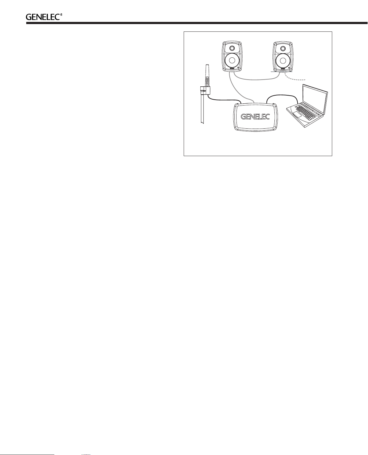
Setting Up the GLM™ Control Network
Figure 1. GLM control network cabling
• Place the Genelec measurement microphone at the listening
location of the engineer, on a stand, with the microphone
pointing upwards and the microphone top at the height of the
engineers ear in normal working position. The microphone is a
part of the GLM User Kit.
• Run the microphone cable to the microphone input in the
GLM Adapter device.
• Download GLM software at the Genelec web site (www.
genelec.com). Install the GLM software.
• Follow the GLM software instructions to measure and set up
your monitors.
• If you plan to not use a computer for controlling the
monitors, use the GLM software to write the setting into the
monitors (“Store the Settings”).
Using the Monitors in Stand-Alone Mode
When the monitors are not connected to a Genelec monitor control network, they operate in the stand-alone mode.
However, settings made with the Genelec Loudspeaker Manager software can be saved into each monitor and applied
even when the network is disconnected by setting switch 1
“STORED/MANUAL CONTROL” on switch group 2 of each
monitor to position “STORED.”
Although the 8240A, 8250A, 8351A and 8260A can be used without the GLM™ software and control network, they only reach
their full potential when set up and calibrated using the GLM™
software. The setup is fast and consists of the following steps:
• Run a CAT5 (RJ45) cable from the monitor control network
to the next monitor (see Figure 1).
• Run the final cable to control network input of the GLM
Adapter device.
• Connect the GLM Adapter device to your computer USB
connector. The cable
is a part of the GLM User Kit
.
2
All issues concerning use with the network are explained
in detail in the System Operating Manual provided with the
GLM™ Loudspeaker Manager software kit.
Connections
Each monitor is supplied with a mains cable, one 5 m GLM
network cable and an operating manual. Before connecting
up, ensure that the mains switch is off.
“MAINS INPUT” Connector
Connect the mains supply to this connector.
Page 3
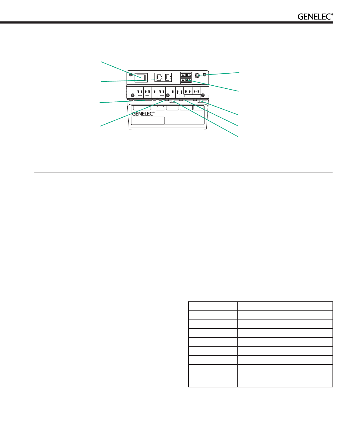
Mains power
switch
Analog input connector
GLM Control
Network
connectors
Mains input
connector
12V Remote
connector
(8260A only)
SWITCH
1
ROLL-OFF
-2dB -4dB
MAINS INPUT 230 V~
50/60Hz 330W
BASS
BASS
TILT
-4dB
-2dB -4dB
+2dB -4dB
160Hz
-6dB -6dB -2dB
REMOTE
SERIALNUMBER
1
2
TREBLE
STOREDDESKTOP
TILT
AB
ON
OFF
MANUAL
ON+ON
OFF+OFF
CTRL
12 V
DIGITALIN
AES/EBU
8260A DSP TRI-AMPLIFIED
MONITORING SYSTEM
MAGNETICALLYSHIELDED
MADE IN FINLAND
ON
OFF
ON
OFF
DIGITAL THRU
DRIVERMUTE
WF COAX
SUMAANDB
AES/EBU
www.genelec.com
-8
-6
-10
-4
-2
-12
0
dB
SYSTEMLVL.AES/EBUCH.
SWITCH
-10-20
2
-30
dB
ANALOG
IN
292-8260T-6
Stand-alone user
interface level control
Stand-alone user
interface switch
groups 1 and 2
Digital Thru connector
Digital input connector
Figure 2. Connectors and controls on the back panel of a 8260A. 8240A, 8250A and 8351A share the same layout but
without the 12 V trigger voltage connector.
“DIGITAL IN AES/EBU” Connector
Use this female XLR connector for AES/EBU formatted digital
audio input signals. This input is selected automatically when
a valid digital audio signal is present, and overrides the analog
input.
Depending on the digital hardware, transmission of a 192 kHz
sample rate is achieved using a double speed, single channel/cable interface. This is called dual-wire mode. In this case
one cable per channel is used and no channel selection is
required. Dual-wire mode is automatically detected by the input stage.
If the digital source device has a volume fader that controls
the digital level, it may be advantageous to lower the level
control either on the computer interface or on the monitor’s
back panel controls, which in turn will force the use of more of
the digital [bit] resolution in the volume control.
If the digital inputs are used, all audio outputs are referenced
to 0 dBFS (digital Full Scale, the largest level that may be represented in the AES/EBU signal). These monitors produce 100
dB SPL at 1 meter in free space for a digital input signal of
–30 dB FS.
“DIGITAL THRU AES/EBU” Connector
This male XLR carries an unaltered copy of the digital signal
fed into the “DIGITAL IN AES/EBU” connector. It can be used
for daisy-chaining up to four monitors together.
+22.0 dBu RMS on models 8351A and 8260A. When A/D converter input clip occurs the front panel light turns momentarily
red, indicating the overload condition.
“CONTROL NETWORK” Connectors
Use these RJ-45 sockets to connect the monitor to the proprietary Genelec Loudspeaker Manager™ (GLM™) network only.
This connector is not Ethernet LAN compatible. Do not connect to Ethernet LAN.
“12 V REMOTE” Connector (8260A only)
You can set up remote controlled powering up and down of
the 8260A with 12 V voltage connected to this connector. The
minimum current needed to actuate this function is 70 mA.
Front Panel Warning Light
Device LED action Meaning and resolution
Steady green
Slowly blinking green
From yellow to green
Steady yellow
Flashing red
Flashing red
Flashing red
Flashing yellow
Normal state
Normal ISS power save state
Normal operation during device start
Monitor or subwoofer is not part of the group
Signal clip (analog)
Bit errors in incoming digital AES/EBU audio
Digital signal potential clip (digital audio is very
close to 0 dB FS)
Protection
“ANALOG IN” Connector
Use this connector for analog audio signals. The maximum
input level is +7.0 dBu RMS on models 8240A and 8250A and
Table 1. Monitor and subwoofer front panel light indications
summary
3
Page 4
ACOUSTIC
> 0,7 m
8260A: h=448 mm (17 5/8 )
in
h
AXIS
8240A: h=240 mm (9 7/16 )
8250A: h=290 mm (11 1/2 )
8351A: h=235 mm (9 1/4 in)
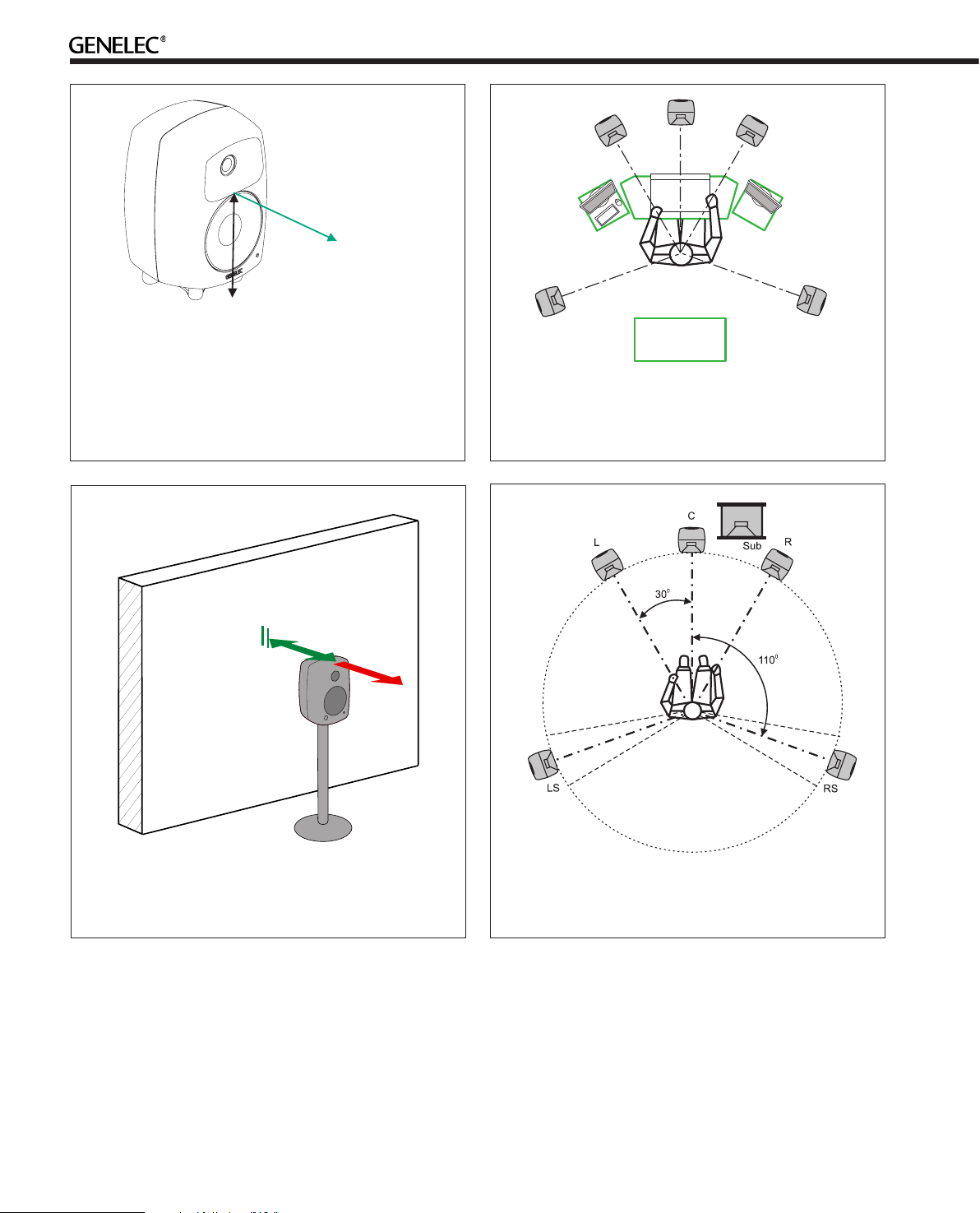
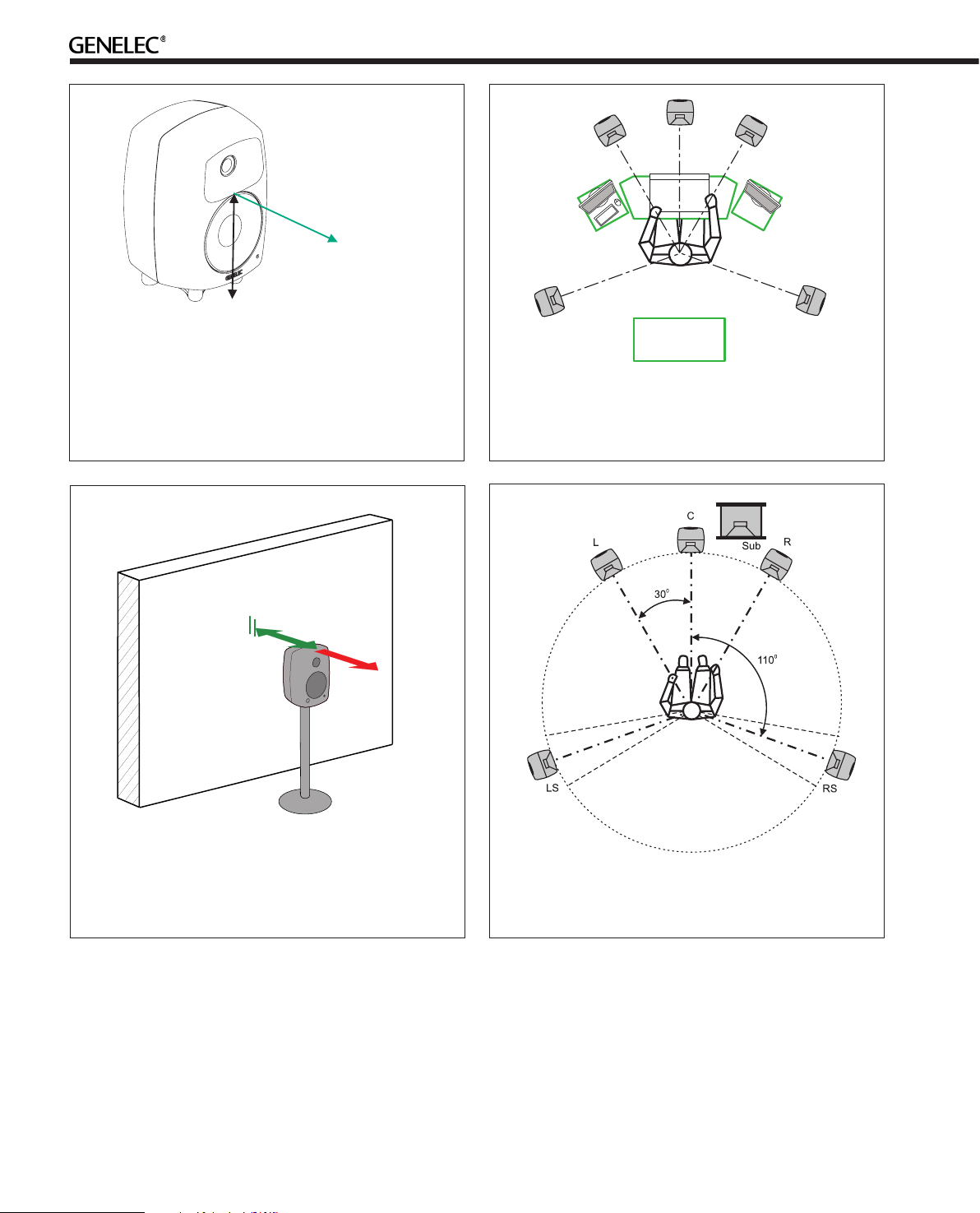
Figure 3. The location of the acoustic axis is on the centerline of the monitor at the given height “h”. The acoustic
axis of the 8351A and 8260A is located at the center of
the coaxial driver.
in
in
Max
60 cm
Min 5 cm
Avoid
> 60 cm
Figure 4. Symmetrical layout and keeping the acoustic
axis clear from obstructions minimizes reflection surfaces
and maintains accurate localisation because reflections
are symmetrical.
Figure 5. Recommended distances from a single wall to
the front baffle of free-standing monitors. Correct (green)
and not recommended (red).
If a red warning light appears, turn the analog source down!
If the levels are already modest and a digital signal is being
used, ensure that there are no bit errors in the AES/EBU digital
audio data.
4
Figure 6. Recommended monitor positioning for 5.1 multichannel audio reproduction
Mounting Considerations
Align the Monitors Correctly
Place the monitors so that their acoustic axes are aimed towards the listening position (see Figure 3). Vertical placement
is preferable, as it minimises acoustical cancellation problems
around the crossover frequency.
Page 5
Maintain Symmetry
Check that the monitors are placed symmetrically and at an
equal distance from the listening position. If possible, place
the system so that the listening position is on the centerline
of the room and the monitors are placed at an equal distance
from the centerline (See Figure 4).
Minimise Reflections
Acoustic reflections from objects close to the monitors like
desks, cabinets, computer monitors etc. can cause unwanted
colouration and blurring of the sound image. These can be minimised by placing the monitor clear of reflective surfaces. For
instance, putting the monitors on stands behind and above the
mixing console usually gives a better result than placing them
on the meter bridge. Symmetrical positioning of the reflective objects is also important in order to maintain a balanced
soundstage (See Figure 4).
Low Frequency Cancellations
In general, when a monitor’s front baffle is more than 0.3 meters (1 foot) away from the wall behind the monitor, a reflection
from this wall can cause a cancellation of low frequencies and
hence reduction of bass output. Distances between 1 and 2.2
meters (3-7 ft.) should be avoided (See Figure 5).
As a rule of thumb, the lower the low frequency cut-off the
further away the monitor must be placed from the wall in order
to avoid this phenomenon.
Distances to the ceiling and other walls may be shorter than the
distance to the wall behind a monitor. Reflections from these
surfaces may be important and should also be considered
Operating Environment
These monitors are designed for indoor use only. The permissable ambient temperature is 15-35 degrees Celsius (50-95°F) and
permissable relative humidity between 20% and 80%. Humidity
condensation on the product is not allowed during use. If the
product has been stored or transported in a cool environment
and then taken into a warm room, it must be allowed to warm
up completely before connecting to mains power.
Sufficient cooling for the amplifier and functioning of the reflex
port must be ensured if the monitor is installed in a restricted
space such as a cabinet, or integrated into a wall structure.
The surroundings of the monitor must always be open to the
listening room with a minimum clearance of 5 centimeters (2”)
behind, above and on both sides of the monitor. The space
adjacent to the monitor must either be ventilated or sufficiently large to dissipate heat so that the ambient temperature
does not rise above 35 degrees Celsius (95°F).
Mounting Options
The vibration insulating Isolation Positioner/Decoupler™ (IsoPod™) table stand allows tilting of the monitor for correct
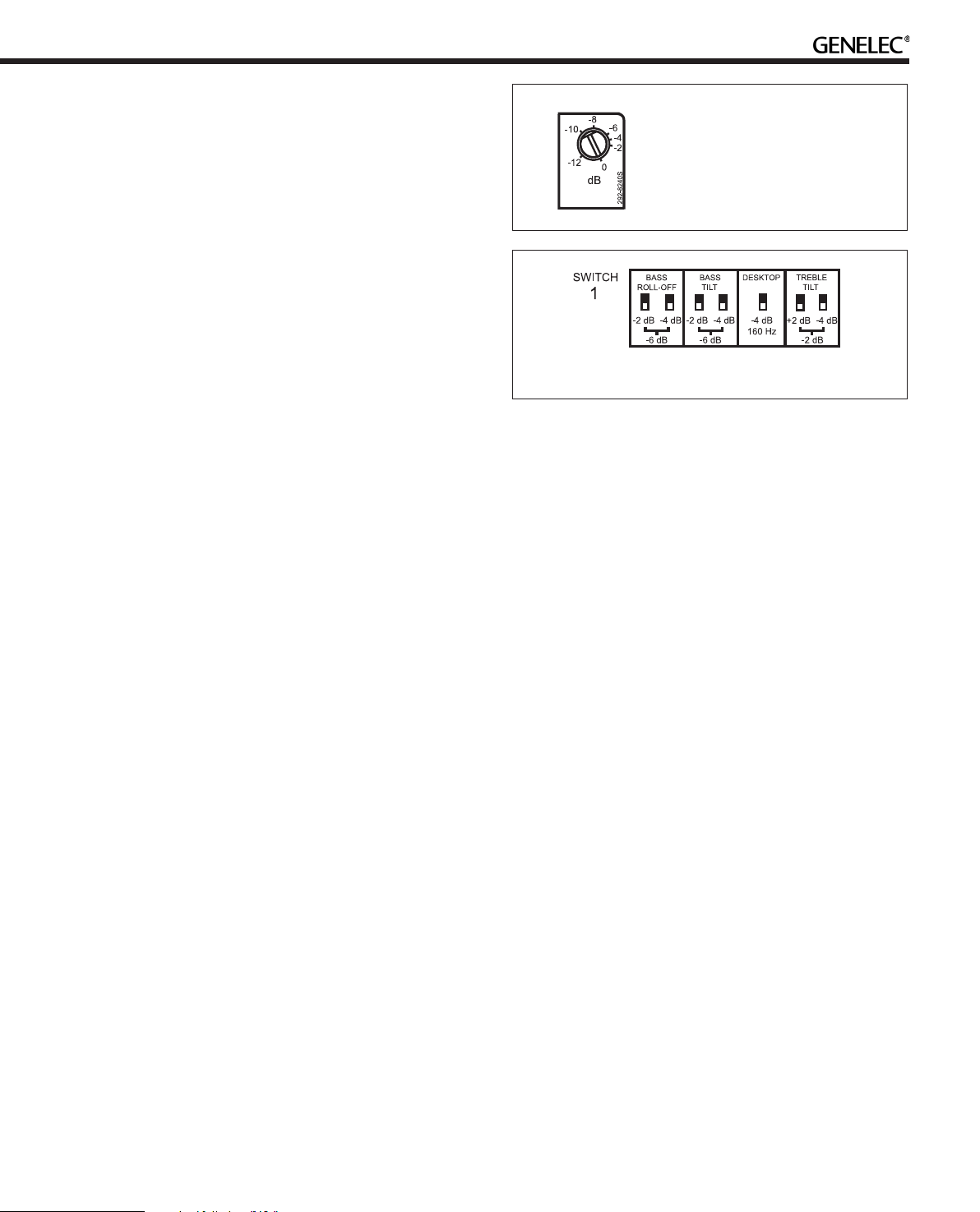
Figure 7. System Level rotary control
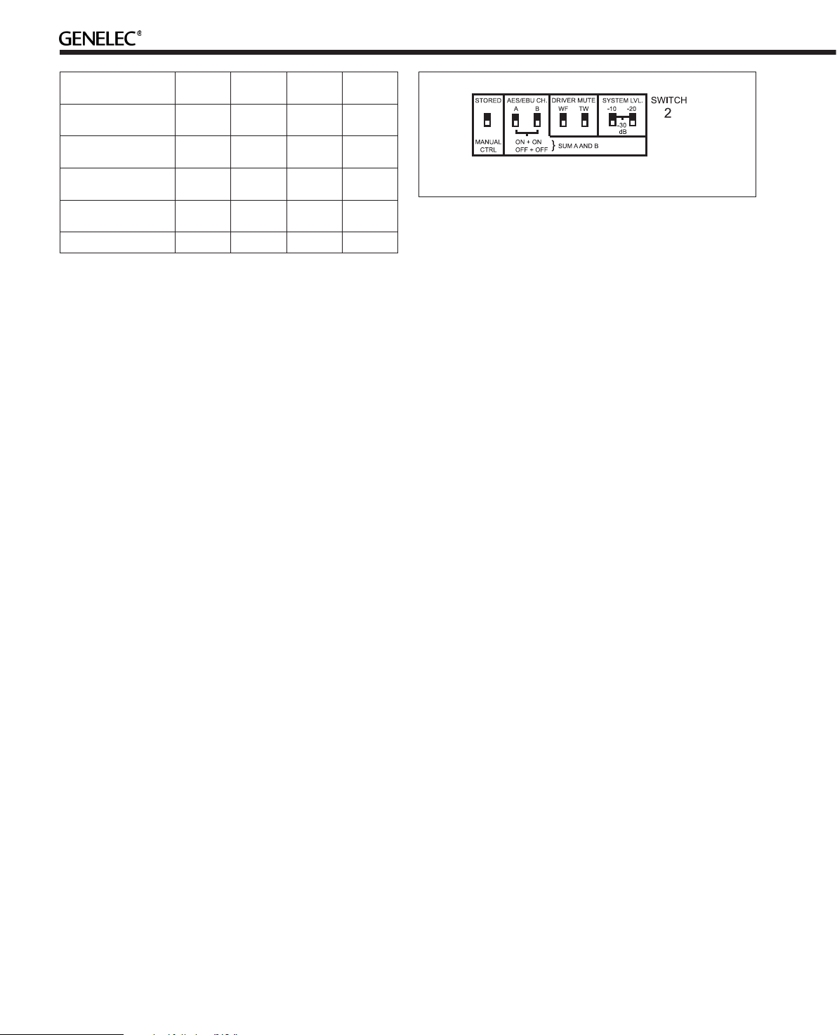
Figure 8. Switch Group 1
alignment of the acoustic axis. The stand can be attached to
three mounting points allowing vertical and symmetrical horizontal positioning.
Genelec 8240A, 8250A, 8351A and 8260A can be fitted to König
& Meyer monitor mounts on two sets of M6x10 mm threaded
holes on the back of the enclosure. On the base of the 8240A
and 8250A enclosure is an M10x10 mm threaded hole which
can be used for securing the monitor to its base. Do not use
this thread for mounting the monitor on a microphone stand
which has a 3/8” UNC thread. A wide variety of ceiling and wall
mounts are available through your Genelec dealer.
Setting the Input Sensitivity
The monitor level sensitivity functions for both analog and digital input. The sensitivity can be matched by adjusting the rotary
Level control together with the System Level switches located
in the switch group 2. (switches 6 and 7). The switches provide
attenuation levels of -10 dB (sw. 6 ON), -20 dB (sw. 7 ON) and
-30 dB (both switches ON) The combined attenuation ranges
from 0 to -42 dB.
Functions On Switch Group 1
(Tone Controls)
Switch group 1 (the upper switch group) comprises the tone
controls that can adjust the frequency response of the system in stand-alone mode to match the acoustic environment.
Please note that the GLM software allows a much more versatile and precise set of controls to be used and supports the
fully automatic system alignment feature, the Genelec AutoCal. Use the tone control switches on the monitor only if GLM
is not available for the system calibration.
The controls are labelled “TREBLE TILT”, “BASS TILT”, “BASS
ROLL-OFF” and “DESKTOP”. The factory settings for these
5
Page 6
Monitor
Mounting Position
Flat anechoic
response
Free standing in
a damped room
Free standing in
a reverberant room
Near field on
a reflective surface
In a corner None -4 dB -4 dB None
Treble
Tilt
None None None None
None -2 dB None None
None -4 dB None None
None -2 dB None -4 dB
Bass
Tilt
Bass
Roll-Off
Desktop
Figure 9. Switch Group 2
Functions On Switch Group 2
Table 2. Suggested Tone Control settings for some typical
monitor placement positions.
controls are all “OFF” to give a flat anechoic response. Note
that these controls have no effect when switch 1 “STORED/
MANUAL CONTROL” on switch group 2 is set to “STORED” or
when the monitor is connected to the Genelec monitor control
network.
The use of an acoustic measurement system is recommended to analyze the effects of the adjustments, however, careful
listening with suitable test recordings can also lead to good
results if a test system is not available. Start adjustment by
setting all switches to “OFF” position. Measure or listen systematically through the different combinations of settings to
find the best frequency balance. See Table 2 for some typical
settings.
Bass Roll-Off Control
Bass Roll-Off control (switches 1 and 2) attenuates its output
near the cut-off frequency. Attenuation levels of -2 dB (sw.
1 ON), -4 dB (sw. 2 ON) or -6 dB (both switches ON) can be
selected.
Bass Tilt Control
The Bass Tilt control switches (swiches 3 and 4) offer three
attenuation levels for the bass response below 800 Hz, usually
necessary when the monitors are placed near room boundaries. The attenuation levels are -2 dB, -4 dB and -6 dB.
Desktop Low Frequency Control
The desktop low frequency control (switch 5) attenuates the
bass frequencies around 160 Hz by 4 dB. This feature is designed to compensate for the boost often occurring at this
frequency range when the monitor is placed upon a meter
bridge, table or similar reflective surface.
Treble Tilt Control
Treble Tilt control (switches 6 and 7) allows adjusting the treble response above 5 kHz by +2 dB, -2 dB or -4 dB, which can
be used for correcting an excessively bright or dull sounding
system or to compensate for high frequency level loss if the
monitor is placed behind a screen.
Stored / Manual Ctrl
“MANUAL CTRL” refers to controlling the monitor using the
controls on the monitor’s back panel. The “STORED” refers to
using settings stored inside the memory of the monitor. These
settings are made using the GLM and the GLM Control Network. There is additional functionality compared to that offered
by the room response correction switches on the back panel.
AES/EBU CH
This selects the audio channel(s) available on the AES/EBU
cable to be reproduced by the monitor. Turning both switches
on reproduces the sum of the two channels on the AES/EBU
cable. Turning both switches off mutes the monitor. When two
channels are selected, 6 dB of attenuation is automatically
applied to avoid overloading the monitor.
If the AES/EBU cable is operated in dual-wire mode, the
monitor detects this situation automatically and the channel
selection switches have no effect.
Driver Mute
These two switches allow you to mute the treble driver (marking “TW”) and bass driver (marking “WF”) independently. This
may be useful to diagnose if a transducer is faulty. On the
8351A and 8260A the marking “TW” is replaced with “COAX”
and this switch mutes both the treble and midrange of the
coaxial driver unit.
System Lvl
These switches allow scaling down of the monitor output. The
signal sent to the “Thru” output connector is not affected. The
switches are additive, for example, “–30 dB” attenuation is
achieved by turning on the “–10 dB” and “–20 dB” switches.
The effect of these switches is combined with the effect of the
rotary level adjustment control. This results in total possible
attenuation of 42 dB, 30 dB by the system level switches and
another 12 dB by the rotary control.
Using the 7000 Series Analog Subwoofers
with SAM Monitors
Please follow the steps below to integrate an analog subwoofer into a system of SAM monitors:
6
Page 7

• Connect cables carrying analog audio to the 7000 Series
analogue subwoofer first.
• Connect the subwoofer outputs to the analog inputs of the
SAM monitors.
• Connect the GLM Control Network to the monitors.
• Make a System Setup in GLM. It will consist of only
monitors as this is all the network can see, so suitable
Rapid Cabling Presets are “Stereo Pair (Analog)” and “5.0
Surround System (Analog)”.
• Run AutoCal and review the results to check for large dips
at or above 85 Hz. Move the monitors and repeat AutoCal if
there is a problem.
• Press “Finish”, then in the Main Page select “Menu | Store
Acoustic Settings to All Online Monitors” and close GLM.
• For each SAM monitor, turn it off, select “Stored” on the
back of each monitor to activate the internal Acoustic
Settings, and then turn it on again.
• To set the phase control on the subwoofer, connect the
Center channel output of the subwoofer to the monitor to be
used to align phase.
• Follow the instructions in the subwoofer user manual for
setting phase and level.
Maintenance
No user serviceable parts are to be found within the monitor
enclosure. Any maintenance or repair of the monitor should
only be undertaken by a certified Genelec service.
lation. This equipment generates, uses and can radiate radio
frequency energy and, if not installed and used in accordance
with the instructions, may cause harmful interference to radio
communications. However, there is no guarantee that interference will not occur in a particular installation. If this equipment
does cause harmful interference to radio or television reception, which can be determined by turning the equipment off and
on, the user is encouraged to try to correct the interference by
one or more of the following measures:
• Reorient or relocate the receiving antenna.
• Increase the separation between the equipment and
receiver.
• Connect the equipment into an outlet on a circuit different
from that to which the receiver is connected.
• Consult the dealer or an experienced radio/TV technician for
help.
Modifications not expressly approved by the manufacturer
could void the user’s authority to operate the equipment under FCC rules.
Safety Considerations
Although the 8240A, 8250A, 8351A and 8260A have been designed in accordance with international safety standards, to
ensure safe operation and to maintain the monitor under safe
operating conditions, the following warnings and precautions
must be observed:
Guarantee
Genelec 8240A, 8250A, 8351A and 8260A are supplied with a
two year guarantee against manufacturing faults or defects
that might alter the performance of the monitors. Refer to supplier for full sales and guarantee terms.
Accessories
A wide selection of accessories is available for Genelec monitors. Consult the Accessories Catalogue on www.genelec.
com or your local distributor/dealer for up-to-date information.
Compliance to FCC Rules
This device complies with part 15 of the FCC Rules. Operation
is subject to the following two conditions:
• This device may not cause harmful interference, and
• This device must accept any interference received, including
interference that may cause undesired operation.
Note: This equipment has been tested and found to comply
with the limits for a Class B digital device, pursuant to part 15 of
the FCC Rules. These limits are designed to provide reasonable
protection against harmful interference in a residential instal-
• Servicing and adjustment must only be performed by a
certified Genelec service. The monitor enclosure must not
be opened.
• Do not use this product with an unearthed mains cable or
a mains connection without the protective earth contact as
this may lead to personal injury.
• To prevent fire or electric shock, do not expose the unit to
water or moisture.
• Do not place any objects filled with liquid, such as vases
on the monitor or near it.
• Note that the amplifier is not completely disconnected
from the AC mains service unless the mains power cord is
removed from the amplifier or the mains outlet.
• Free flow of air behind the monitor is necessary to maintain
sufficient cooling.
• Do not obstruct airflow around the monitors.
WARNING!
These monitors are capable of producing sound pressure levels in excess of 85 dB, which may cause permanent hearing
damage.
7
Page 8
Hz
Genelec Oy 8250A (dBr) vs freq (Hz) 17 Jan 06
80
85
90
d
B
r
A
BASS ROLL-OFF
TREBLE TILT
80
85
90
80
85
90
DESKTOP LF
BASS TILT
Hz
Genelec Oy 8250A (dBr) vs freq (Hz) 17 Jan 06
0°
60°
15°
30°
45°
50
100
55
60
65
70
75
80
85
90
95
d
B
r
A
Hz
Genelec Oy 8351A dBr) vs freq (Hz) 20 Nov 2014
80
85
90
d
B
r
A
BASS ROLL-OFF
TREBLE TILT
80
85
90
80
85
90
DESKTOP LF
BASS TILT
20k
Hz
Genelec Oy 8351A (dBr) vs freq (Hz) 20 Nov 2014
0°
60°
15°
30°
45°
50
100
55
60
65
70
75
80
85
90
95
d
B
r
A
Hz
Genelec Oy 8240A (dBr) vs freq (Hz) 17 Jan 06
80
85
90
d
B
r
A
DESKTOP LF
BASS TILT
BASS ROLL-OFF
TREBLE TILT
80
85
90
80
85
90
100
Hz
Genelec Oy 8240A horizontal off axis response level (dBr) vs freq (Hz) 17 Jan 06
0°
60°
15°
30°
45°
50
100
55
60
65
70
75
80
85
90
95
d
B
r
A
200
20
100
200
20
50
500
1k 2k
5k
20k
10k
50
500
1k 2k
5k
20k
10k
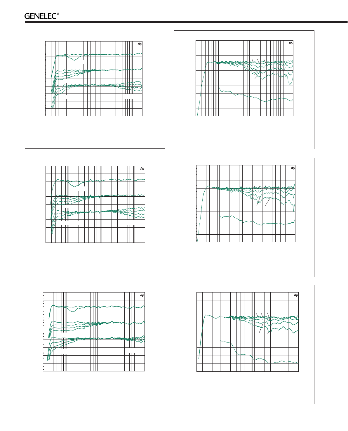
Figure 10. The curves above show the effect of the “Bass
Tilt”, “Treble Tilt”, “Desktop Low Frequency” and “Bass
Roll-Off” controls on the free field response of the 8240A.
100
200
20
50
500
1k 2k
5k
20k
10k
Figure 12. The curves above show the effect of the “Bass
Tilt”, “Treble Tilt”, “Desktop Low Frequency” and “Bass
Roll-Off” controls on the free field response of the 8250A.
Figure 11. The upper curve group shows the horizontal
directivity characteristics of the 8240A measured at 1 m.
The lower curve shows the system’s power response.
100
200
20
50
500
1k 2k
5k
20k
10k
Figure 13. The upper curve group shows the horizontal
directivity characteristics of the 8250A measured at 1 m.
The lower curve shows the system’s power response.
20
50
Figure 14. The curves above show the effect of the “Bass
Tilt”, “Treble Tilt”, “Desktop Low Frequency” and “Bass
Roll-Off” controls on the free field response of the 8351A.
8
100
200
500
1k 2k
5k
20k
10k
20
100
200
50
500
1k 2k
5k
10k
Figure 15. The upper curve group shows the horizontal
directivity characteristics of the 8351A measured at 1 m.
The lower curve shows the system’s power response.
Page 9

20k
Hz
Genelec Oy 8260A (dBr) vs freq (Hz) 12 Jan 11
80
85
90
d
B
r
A
DESKTOP LF
BASS TILT
BASS ROLL-OFF
TREBLE TILT
80
85
90
80
85
90
100
Hz
Genelec Oy 8260A (dBr) vs freq (Hz) 12 Jan 11
0°
60°
15°
30°
45°
50
100
55
60
65
70
75
80
85
90
95
d
B
r
A
200
20
100
200
20
50
500
1k 2k
5k
10k
50
500
1k 2k
5k
20k
10k
Figure 16. The curves above show the effect of the “Bass
Tilt”, “Treble Tilt”, “Desktop Low Frequency” and “Bass
Roll-Off” controls on the free field response of the 8260A.
Figure 18. 8240A horizontal directivity plot.
Figure 17. The upper curve group shows the horizontal
directivity characteristics of the 8260A measured at 1 m.
The lower curve shows the system’s power response.
Figure 19. 8240A vertical directivity plot.
Figure 20. 8250A horizontal directivity plot.
Figure 21. 8250A vertical directivity plot.
9
Page 10

Figure 22. 8351A horizontal directivity plot.
Hz
Genelec Oy 8260A (dBr) vs freq (Hz) 12 Jan 11
75
80
85
90
95
d
B
r
A
40k
Figure 23. 8351A vertical directivity plot.
Figure 24 8260A horizontal directivity plot.
100
200
20
50
500
1k 2k
5k
20k
10k
Figure 26. 8260A on-axis free field response up to
40 kHz .
Figure 25. 8260A vertical directivity plot.
10
Page 11

SPECIFICATIONS
8240A 8250A 8351A 8260A
Drivers
Bass
Midrange
Treble
Free field frequency response of system
Accuracy of frequency response
Maximum peak SPL output per pair
on top of console at 1 m with music material
Maximum short term sine wave SPL output at
1 m on axis in half space, averaged as specified
Crossover frequency
Self generated noise level in free
field @ 1 m on axis (A-weighted)
Input signal
Analog
AES/EBU (single wire and dual wire)
Output / Thru signal
AES/EBU (single wire and dual wire) 1 XLR male (conforms to IEC 60958-4)
Digital audio
Word length
Sample rate
Analog input level for 100 dB SPL at 1 m -6 dBu
Maximum analog input signal +7 dBu +7 dBu +21 dBu +21 dBu
Control network
Type
Connection
GLMTM software frequency response adjustment*
Notch filters
Shelving filters
System calibration * AutoCalTM, GLMTM manual, Stand-alone
Bass amplifier output power
Midrange amplifier output power
Treble amplifier output power
(Long term output power is limited by driver
protection circuitry)
Power consumption
Idle
Full output
Dimensions
Height
Width
Depth
Height with Iso-Pod™
Weight
* The notch and shelving filters adjustments, AutoCalTM and GLM
165 mm (61/2 in)
n/a
19 mm (3/4 in) metal dome
41 Hz - 23 kHz
(- 6 dB)
48 Hz - 20 kHz
(± 1.5 dB)
≥ 115 dB SPL ≥ 120 dB SPL
(from 100 Hz to 3 kHz)
≥ 105 dB SPL
3 kHz 1.8 kHz 470 Hz, 2.6 kHz 490 Hz, 2.6 kHz
≤ 5 dB ≤ 5 dB ≤ 5 dB ≤ 5 dB
90 W
n/a
90 W
14 W
110 W
350 mm (1313/16 in)
237 mm (93/8 in)
223 mm (813/16 in)
365 mm (143/8 in)
9.4 kg (20.8 lb) 14.6 kg (32 lb) 19 kg (42 lb) 27.5 kg (60.5 lb)
TM
manual system calibration features are part of the Genelec Loudspeaker Manager (GLMTM) software
205 mm (8 in)
n/a
25 mm (1 in) metal dome
32 Hz - 23 kHz
(- 6 dB)
38 Hz - 20 kHz
(± 1.5 dB)
(from 100 Hz to 3 kHz)
≥ 110 dB SPL
1 XLR female (10 kOhm input load impedance)
2 LF and 2 HF
2 LF and 2 HF
150 W
n/a
120 W
17 W
170 W
433 mm (171/16 in)
286 mm (111/4 in)
278 mm (1015/16 in)
452 mm (1713/16 in)
Dual 8 1/2 x 4 in
120 mm (5 in) Coax
Al-cone
19 mm (3/4 in) Coax
Al-dome
32 Hz - 35 kHz
(- 6 dB)
38 Hz - 20 kHz
(± 1.5 dB)
≥ 121 dB SPL ≥ 123 dB SPL
(from 100 Hz to 3 kHz)
≥ 111 dB SPL
1 XLR female (conforms to IEC 60958-4)
16 - 24 bits
32 - 192 kHz
proprietary GLMTM network
2 RJ45, CAT5 cables
150 W
120 W
90 W
20 W
290 W
433 mm (171/16 in)
286 mm (111/4 in)
278 mm (1015/16 in)
452 mm (1713/16 in)
255 mm (10 in)
120 mm (5 in) Coax
Al-cone
19 mm (3/4 in) Coax
Al-dome
23 Hz - 40 kHz
(- 6 dB)
29 Hz - 20 kHz
(± 1 dB)
(from 100 Hz to 3 kHz)
≥ 113 dB SPL
4 LF and 2 HF
2 LF and 2 HF
150 W
120 W
120 W
26 W
330 W
570 mm (227/16 in)
357 mm (141/16 in)
347 mm (135/8 in)
593 mm (233/8 in)
11
Page 12

Einführung
Abhörposition
Mikrofon
GLM Netzwerk
USB
GLM
Netzwerk
GLM
Netzwerk
Herzlichen Glückwunsch und vielen Dank für den Kauf Ihres
Genelec SAM-Systems. Alle Genelec SAM-Systeme sind so
konzipiert, dass sie sich einfach in eine digitale Produktionsumgebung integrieren lassen.
Es gibt verschiedene Möglichkeiten, die SAM-Systeme zu nutzen und diese für eine Vielzahl von hochwertigen Audio-Anwendungen zu konfigurieren. Die SAM-Monitore verfügen auch über
analoge Eingänge und werden zu einer vielseitigen und anpassungsfähigen Alternative zu analogen Standardmonitoren.
Dieses Handbuch befasst sich mit der Einrichtung und Nutzung der 8240A, 8250A, 8351A und 8260A SAM-Monitore
im Stand-Alone-Betrieb ohne die Verwendung der Genelec
Loudspeaker Manager- GLM™ Software.
Wenn Sie die GLM Software verwenden, lesen Sie bitte die
Bedienungsanleitung, welche im Lieferumfang der Software
enthalten ist.
System
Die Genelec SAM-Monitore 8240A, 8250A, 8351A und 8260A
sind für das präzise Abhören von digitalen AES/EBU Audiosignalen von bis zu 24 Bit/192 kHz Auflösung oder analogen Audiosignalen mit Line-Pegel geeignet. Sie sind kompatibel zur
Genelec Loudspeaker Manager-GLM Software und dem proprietären Genelec-Monitor-Steuernetzwerk. Die passenden
Subwoofer sind 7260A, 7270A und 7271A. Selbstverständlich
können die Monitore auch ohne zusätzlichen Subwoofer genutzt werden. 8240A, 8250A, 8351A und 8260A bieten hohe
Schallpegel und einen breiten verfärbungsfreien Frequenzbereich in einem kompakten Gehäuse.
Sie eignen sich für eine Vielzahl von Aufgaben wie z. B. Nahfeld-Monitoring, Nutzung in Ü-Wagen, Studios in Rundfunk
und Fernsehen, Mehrkanal-Sound-Systemen und Heim-Studios.
Die Minimum Diffraction Enclosure (MDE™) und Minimum
Diffraction Koaxial (MDC™) Technologien ermöglichen einen
absolut ausgewogenen und linearen Frequenzgang auch in
akustischen schwierigen Umgebungen.
Verstärker
Die Verstärkereinheiten sind direkt im Gehäuse des Monitors
montiert und verfügen über spezielle Schutz-Schaltungen für
thermische Überlastung der Treiber. Variable Eingangsempfindlichkeiten ermöglichen eine präzise Pegelanpassung an
die angeschlossenen Audioquellen.
Abbildung 1: GLM Kontroll-Netzwerk-Verkabelung
Einrichten des GLM™ Control Network
Obwohl die 8240A, 8250A, 8351A und 8260A auch ohne die
GLM Software und das Steuernetzwerk verwendet werden
können, ist es empfehlenswert, die GLM Software zu verwenden, damit Sie das volle Potential der Lautsprecher nutzen
können.
Die Einrichtung erfolgt unkompliziert mit den folgenden
Schritten:
• Verbinden Sie mit einem CAT5 (RJ45) Kabel den ersten
Genelec Lautsprecher mit dem nächsten (siehe Abbildung 1).
• Verbinden Sie den letzten Lautsprecher mit dem
Netzwerkeingang des GLM Netzwerkinterfaces.
• Schließen Sie das GLM Netzwerkinterface mit dem USB
Kabel an den Computer an. Das USB Kabel gehört zum
Lieferumfang des GLM Kits.
• Stellen Sie das Genelec Messmikrofon an der Hörposition
auf einem Mikrofonständer auf. Das Mikrofon sollte nach
oben zeigen und in Ohr-Höhe aufgestellt werden. Das
Mikrofon ist Teil des Lieferumfangs des GLM Kits.
• Verbinden Sie das Mikrofonkabel mit dem Mikrofoneingang
am GLM Netzwerkinterface.
• Laden Sie die aktuelle GLM-Software von der Genelec
Website (www.genelec.com) herunter und installieren Sie
diese auf Ihrem PC/Mac.
• Folgen Sie den Anweisungen der GLM-Software zur
Einmessung und Einrichtung Ihres Monitor-Setups.
• Wenn Sie die GLM Software nicht zur permanenten
Steuerung der Lautsprecher verwenden wollen, speichern
Sie die Einmessung und Einstellungen einfach dauerhaft in
den Lautsprechern (Store Settings).
12
Page 13

Pegelsteller
Netzschalter
-8
-6
GLM Kontroll-
Netzwerk-
Buchsen
Buchse für
Netzkabel
12 Volt
SWITCH
1
ROLL-OFF
-2dB -4dB
MAINS INPUT230 V~
50/60Hz 330W
BASS
BASS
TILT
-4dB
-2dB -4dB
160Hz
-6dB -6dB -2 dB
REMOTE
SERIALNUMBER
TREBLE
STOREDDESKTOP
TILT
ON
OFF
+2dB -4dB
MANUAL
CTRL
12 V
DIGITALIN
AES/EBU
8260A DSP TRI-AMPLIFIED
MONITORING SYSTEM
MAGNETICALLYSHIELDED
MADE IN FINLAND
1
2
AB
ON+ON
OFF+OFF
ON
OFF
ON
OFF
DIGITAL THRU
DRIVERMUTE
WF COAX
SUMAANDB
AES/EBU
www.genelec.com
-4
-2
-12
0
dB
SYSTEMLVL.AES/EBUCH.
SWITCH
-10-20
2
-30
dB
ANALOG
IN
292-8260T-6
-10
Fernsteuerungsbuchse
(nur 8260A)
Abbildung 2: Anschlüsse und Schalter auf der Rückseite eines 8260A. 8240A und 8250A und 8351A nutzen das gleiche
Layout - jedoch ohne den 12 V-Trigger-Anschluss
Stand-Alone
Stand-Alone
Dippschalter
Gruppe1und 2
Analog Eingangsbuchse
Digital Ausgangsbuchse
Digital Eingangsbuchse
Verwendung der Monitore im
Standalone-Modus
Wenn die Monitore nicht mit dem Genelec Netzwerk verbunden sind, arbeiten sie im Standalone-Modus. Alle Einstellungen, die mit der GLM Software gemacht wurden, können aber
in den Lautsprechern gespeichert werden. Diese Settings
werden über den Dip-Schalter 1 der zweiten Schaltergruppe
mit der Schaltung auf “STORED” (ON) aktiviert. Diese Einstellung muss bei jedem Lautsprecher vorgenommen werden.
Alle weiteren Informationen zur Nutzung der GLM Software
finden Sie in der Bedienungsanleitung der Software.
Anschlüsse
Jeder Monitor wird zusammen mit einem Netzkabel, einem 5
m Netzwerk-Kabel und dieser Bedienungsanleitung ausgeliefert. Bitte stellen Sie vor dem Anschließen sicher, dass der
Netzschalter auf OFF steht.
“MAINS INPUT” Anschluss
Verbinden Sie das Netzkabel mit diesem Anschluss.
“DIGITAL IN AES/EBU” Anschluss
Verwenden Sie diese XLR-Buchse für digitale AES/EBU Audio-Eingangssignale. Dieser Eingang wird automatisch ausgewählt, wenn ein gültiges digitales Audiosignal vorhanden
ist, und deaktiviert den Analogeingang.
Abhängig von der digitalen Hardware wird ein 192 kHz Signal mit der doppelten Geschwindigkeit übertragen. Diese Betriebsart wird als Dual-Wire Modus bezeichnet. In diesem Fall
wird ein Kabel pro Kanal benötigt und es ist keine Kanalauswahl erforderlich. Der Dual-Wire Modus wird automatisch von
der Eingangsstufe erkannt.
Wenn das digitale Quellgerät einen Lautstärkeregler hat, der
auf der digitalen Ebene regelt, kann es vorteilhaft sein, den
Pegel auf der Rückseite des Monitors abzusenken. Dadurch
erhalten Sie eine höher Bitauflösung des Digitalsignals.
Bei Verwendung der Digitaleingänge referenzieren alle Audioausgänge auf 0 dBFS (Digital Full Scale, der größtmögliche
Pegel im AES/EBU-Signal). Die Monitore produzieren 100 dB
SPL bei 1 Meter im freien Raum für ein digitales Eingangssignal von -30 dB FS.
“DIGITAL THRU AES/EBU” Anschluss
An diesem XLR Ausgang liegt eine unveränderte Kopie des
digitalen Signals des “DIGITAL IN AES/EBU”-Anschlusses an.
Es kann zur Kaskadierung von bis zu vier weiteren Monitoren
gleichzeitig verwendet werden.
„ANALOG IN” Anschluss
Verwenden Sie diesen Anschluss für analoge Audiosignale.
Der maximale Eingangspegel beträgt +7,0 dBu RMS bei den
Modellen 8240A und 8250A und +22,0 dBu RMS bei den Modellen 8351A und 8260A. Wenn der A/D-Wandler übersteuert
wird, leuchtet die LED auf der Frontseite kurzzeitig rot, welches den Überlastzustand signalisiert
“Control Network” Anschlüsse
Verwenden Sie diese RJ-45-Buchsen, um die Monitore mit
dem proprietären Genelec Loudspeaker Manager (GLM™
) Netzwerk zu verbinden. Dieser Anschluss ist nicht Ethernet-LAN-kompatibel.
13
Page 14
h
8260A: h=448 mm (17 5/8 in)
> 0,7 m
Akustische
Achse
8240A: h=240 mm (9 7/16 )
8250A: h=290 mm (11 1/2 )
8351A: h=235 mm (9 1/4 in)
Abbildung 3: Die Position der akustischen Achse befindet
sich auf der Mittelachse des Lautsprechers auf der angegebenen Höhe “h”. Die akustische Achse beim 8351A
und 8260A befindet sich im Zentrum des Koaxialtreibers
in
in
Max
60 cm
Min 5 cm
Zu vermeiden
> 60 cm
Abbildung 4: Eine symmetrische Aufstellung und die Entfernung von Hindernissen auf der akustischen Achse minimieren reflektierende Oberflächen und stellen eine exakte Lokalisierung sicher, da Reflexionen symmetrisch sind
Abbildung 5: Empfohlene Abstände zwischen Vorderseite
des Lautsprechers und einer Rückwand: geeignet (grün)
und ungeeignet (rot)
“12 V REMOTE” Anschluss (nur 8260A)
Hier können Sie die 8260A mit einer 12V Spannung ein- und
ausschalten. Der erforderliche Mindeststrom beträgt 70 mA.
Warn-LED auf der Frontseite
Im normalen Betrieb leuchtet die LED auf der Frontseite eines
SAM-Monitors grün. Dies zeigt an, dass sich der Monitor im
normalen Betriebszustand befindet. Siehe Tabelle 1.
14
Abbildung 6: Empfohlene Aufstellung für 5.1 MehrkanalWiedergabe
Wird die LED rot, reduzieren Sie den Pegel der analogen Quelle. Wenn ein digitales Signal verwendet wird, stellen Sie sicher,
dass keine Bitfehler im AES/EBU-Datenstrom vorhanden sind.
Montagehinweise
Richten Sie die Monitore richtig aus
Stellen Sie die Monitore so auf, dass ihre akustische Achse
Page 15

LED Anzeige Bedeutung
Grün leuchtend
Langsames grünes
blinken
Wechsel von gelb zu
grün
Gelb leuchtend
Rot blinkend
Rot blinkend
Rot blinkend
Gelb blinkend
Normaler Betrieb
Normaler Betrieb im Stromsparmodus
Startvorgang, normaler Betrieb
Lautsprecher oder Subwoofer ist nicht in der
aktiven Gruppe vorhanden
Übersteuerung des Signals (analog)
Bit-Fehler im eingehenden digitalen AES/EBU
Audiosignal
Digitales Audiosignal ist bis zur 0 dB FS Grenze
ausgesteuert
Schutzschaltung
Tabelle 1. Zusammenfassung der LED Zustände auf der
Vorderseite der Lautsprecher und Subwoofer
Abbildung 7: Pegelregler für die
Eingangsempfindlichkeit
Abbildung 8: Schaltergruppe 1
in Richtung der Hörposition (siehe Abbildung 3) ausgerichtet
ist. Es wird eine vertikale Anordnung empfohlen, da sie akustische Auslöschungsprobleme bei der Übergangsfrequenz minimiert. Der 8351A kann ohne Einschränkung auch horizontal
betrieben werden.
Achten Sie auf Symmetrie
Stellen Sie sicher, dass die Monitore symmetrisch und mit
gleichem Abstand zur Hörpositionen aufgestellt sind. Platzieren Sie die Monitore falls möglich so, dass die Hörposition
auf der Mittelachse des Raumes liegt und die Monitore den
gleichen Abstand von dieser Mittelachse haben (siehe Abbildung 4).
Minimieren Sie Reflexionen
Akustische Reflexionen von Objekten wie Tischen, Schränken, Computerbildschirmen etc., die nahe an den Lautsprechern stehen, können unerwünschte Verfärbungen und ein
unscharfes Stereobild verursachen. Dies kann verhindert
werden, indem die Lautsprecher entfernt von reflektierenden
Oberflächen aufgestellt werden. Beispielsweise führt die Aufstellung auf Stativen über und hinter einem Mischpult häufig
zu besseren Ergebnissen als die Platzierung auf der Meter
Bridge. Eine symmetrische Positionierung der reflektierenden
Objekte ist ebenfalls wichtig, um ein stabiles Stereobild zu erreichen (siehe Abbildung 4).
Tieffrequente Auslöschungen
Grundsätzlich kann eine Reflexion über die Wand hinter dem
Lautsprecher zu einer Auslöschung der tiefen Frequenzen
und damit Reduzierung des Bass-Pegels führen. Dies tritt auf,
sobald die Vorderseite des Monitors mehr als 30 cm von der
Rückwand entfernt ist. Wandabstände zwischen 1 m und 2,2
m sollten vermieden werden (siehe Abbildung 5).
Als Faustregel gilt: Je tiefer die untere Grenzfrequenz eines
Monitors liegt, desto weiter sollte er von der Rückwand entfernt aufgestellt werden, um dieses Phänomen zu umgehen.
Alternativ empfiehlt sich eine wandnahe Aufstellung und
Kompensation der resultierenden Bass-Anhebung über die
Dip-Schalter bzw. die GLM Software.
Die Entfernungen zur Decke und anderen Wänden können
geringer sein als der Abstand zur Rückwand. Reflexionen dieser Oberflächen können sich ebenfalls auswirken und sollten
auch berücksichtigt werden.
Betriebsumgebung
Die Lautsprecher sind ausschließlich zur Nutzung in geschlossenen Räumen konzipiert. Die zulässige Umgebungstemperatur liegt zwischen 15 und 35 Grad Celsius mit einer relativen
Luftfeuchtigkeit von 20-80 Prozent. Das Vorhandensein von
Kondenswasser muss während des Betriebs auf jeden Fall
vermieden werden. Wenn die Lautsprecher in einer kalten Umgebung gelagert oder transportiert wurden und anschließend
in einen warmen Raum gebracht werden, müssen sie sich vollständig an die neue Umgebungstemperatur angepasst haben,
bevor sie mit dem Stromnetz verbunden werden können.
Werden die Lautsprecher in begrenzten Platzverhältnissen wie
einem Schrank oder in der Wand installiert, muss die Kühlung
des Verstärkers und die Funktionalität des Bass-Reflex-Kanals sichergestellt werden. Die Umgebung des Lautsprechers
muss immer zum Abhörraum geöffnet sein. Der Mindestabstand beträgt 5 cm zu allen Seiten. Der angrenzende Bereich
muss belüftet werden oder ausreichend groß sein, damit die
Wärme abgeleitet werden kann und die Temperatur nicht über
35 Grad Celsius steigt.
Montagemöglichkeiten
Der Iso-Pod™-Ständer entkoppelt den Monitor vom Untergrund und ermöglicht die Neigung zur korrekten Ausrichtung
15
Page 16

Platzierung der
Monitore
Freifeld - - - -
Freie Aufstellung in
einem gedämmten
Raum
Freie Aufstellung in
einem halligen Raum
Nahfeld-Aufstellung
auf einer reflektierenden Oberfläche
In einer Ecke - -4 dB -4 dB -
Treble
Tilt
- -2 dB - -
- -4 dB - -
- -2 dB - -4 dB
Bass
Tilt
Bass
Roll-Off
Desktop
Tabelle 2: Empfohlene Einstellung der Klangregelung für typische Platzierungen der Monitore
der akustischen Achse. Der Ständer kann an drei Punkten angebracht werden, die vertikale und symmetrisch horizontale
Positionierung ermöglichen.
8240A, 8250A, 8351A und 8260A haben auf der Rückseite
zwei Paare von M6x10 mm Bohrungen und können mit König&Meyer Halterungen montiert werden. Auf der Unterseite
der 8240A und 8250A gibt es eine M10x10 mm Bohrung, die
dazu genutzt werden kann, den Monitor auf der Stellfläche zu
sichern. Benutzen Sie diese Bohrung nicht zur Montage auf
einem Mikrofonständer mit 3/8“ Gewinde. Über Ihren Genelec
Händler haben Sie Zugriff auf eine große Auswahl an Wandund Deckenhalterungen.
Abbildung 9: Schaltergruppe 2
STORED/MANUAL CONTROL auf STORED (ON) steht oder
wenn der Monitor an das GLM Netzwerk angeschlossen ist.
Die Nutzung eines akustischen Mess-Systems wird empfohlen, um das Resultat der Einstellungen analysieren zu können.
Falls kein System zur Verfügung steht, kann auch aufmerksames Hören mit passenden Aufnahmen zu guten Ergebnissen
führen. Beginnen Sie die Anpassung damit, dass alle Schalter
auf OFF stehen. Messen bzw. bewerten Sie dann systematisch die verschiedenen Einstellungs-Kombinationen, um den
besten Frequenzgang zu bestimmen. Tabelle 2 zeigt Ihnen einige typische Settings.
Bass Roll-Off Regelung
Die Bass Roll-Off Regelung (Schalter 1 und 2) senken den Bereich nahe der unteren Grenzfrequenz ab. Es kann eine Absenkung von -2 dB (Schalter 1 ON), -4 dB (Schalter 2 ON) oder
-6 dB (Schalter 1 und 2 ON) ausgewählt werden.
Einstellen der Eingangsempfindlichkeit
Die Einstellung der Eingangsempfindlichkeit gilt sowohl für
den analogen wie den digitalen Eingang. Die Empfindlichkeit
kann über den Drehregler in Kombination mit den Dip Schaltern der Schaltergruppe 2 angepasst werden. Die Schalter
bieten eine Absenkung von -10 dB (Schalter 6 ON), -20 dB
(Schalter 7 ON) und -30 dB (Schalter 6 und 7 ON). In Kombination mit dem Drehregler umfasst die Absenkung 0 bis -42 dB.
Funktionen der Schaltergruppe 1 (Klangregelung)
Schaltergruppe 1 (die obere Schaltergruppe) umfasst die
Klangregelung zur Anpassung des Frequenzgangs an die Umgebung im Stand-alone-Modus.
Bitte beachten Sie, dass die GLM Software eine wesentlich
präzisere und genauere Anpassung bietet und zudem die
automatische Anpassung über Genelec AutoCal ermöglicht.
Benutzen Sie die Dip Schalter nur, wenn GLM zur Systemeinmessung und Anpassung nicht zur Verfügung steht.
Die Schalter sind mit „TREBLE TILT“, „BASS TILT“, „BASS
ROLL-OFF“ und „DESKTOP“ beschriftet. Die Werkseinstellung dieser Schalter ist OFF, um einen linearen Frequenzgang
im Freifeld zu gewährleisten. Die Position der Schalter hat
keine Auswirkung, wenn in der 2. Schaltergruppe Schalter 1
Bass Tilt Regelung
Die Bass Tilt Control Regelung (Schalter 3 und 4) bieten drei
Absenkungen für den Frequenzbereich unter 800 Hz. Das ist
üblicher Weise sinnvoll, wenn die Monitore nahe an den Wänden platziert sind. Die Absenkung kann mit -2 dB (Schalter 3
ON), -4 dB (Schalter 4 ON) oder -6 dB (Schalter 3 und 4 ON)
erfolgen.
Desktop Low Frequency Regelung
Der Desktop Low Frequency Control Schalter (Schalter 5)
senkt Bassfrequenzen im Bereich 160 Hz um 4 dB ab. Diese
Funktion kompensiert die Anhebung, die typischer Weise in
diesem Frequenzbereich auftritt, wenn der Monitor auf einer
Meter Bridge, einem Tisch oder einer vergleichbaren reflektierenden Oberfläche aufgestellt ist.
Treble Tilt Regelung
Die Treble Tilt Regelung (Schalter 6 und 7) ermöglicht die Anpassung der Höhenwiedergabe über 5 kHz um +2 dB (Schalter 6 ON), -4 dB (Schalter 7 ON) oder – 2 dB (Schalter 6 und 7
ON). Sie können zur Anpassung eines zu hell oder zu dumpf
klingenden Systems genutzt werden oder den Höhenverlust
kompensieren, der auftritt, wenn der Lautsprecher hinter einer
Leinwand montiert wird.
16
Page 17

Funktionen der Schaltergruppe 2
Stored/Manual Ctrl Schalter
„MANUAL CTRL“ bedeutet, dass die Einstellungen auf der
Rückseite des Monitors vorgenommen werden und aktiv sind.
In der Stellung „STORED“ werden die eingespeicherten Settings benutzt. Diese Settings werden über GLM und das GLM
Network vorgenommen. GLM bietet im Vergleich zur Nutzung
der Dip-Schalter eine erweiterte Funktionalität.
AES/EBU CH
Hier wird festgelegt, welcher Kanal bzw. welche Kanäle der
AES/EBU Leitung vom Lautsprecher wiedergegeben werden.
Stehen beide Schalter auf ON, werden die beiden Kanäle der
AES/EBU Leitung summiert wiedergegeben. Beide Schalter
auf Position OFF schalten den Monitor stumm. Wenn beide
Kanäle angewählt sind, wird automatisch eine Absenkung von
-6 dB aktiv, um eine Übersteuerung zur vermeiden.
Wird die AES/EBU Zuleitung im Modus „Dual-Wire“ betrieben,
erkennt dies der Monitor automatisch und die Schalter haben
keinen Einfluss.
Driver Mute
Diese beiden Schalter ermöglichen es, den Hochtontreiber
(TW) und Basstreiber (WF) unabhängig voneinander stumm zu
schalten. Dies kann bei einer Fehlersuche sinnvoll sein.
Bei den Modellen 8351A und 8260A ist die Beschriftung TW
ersetzt durch COAX und der Schalter deaktiviert den Höhenund Mitteltontreiber.
System Lvl
Diese Schalter reduzieren den Ausgangspegel des Monitors.
Das Signal, das an den Thru Ausgang weitergeleitet wird, ist
davon nicht betroffen. Die Schalter arbeiten additiv, -30 dB erreichen Sie durch Schaltung des -10 dB und -20 dB Schalters.
Der Einfluss der Schalter wird kombiniert mit der Einstellung
über den Pegelsteller. So kann insgesamt eine Reduzierung
von -42 dB erreicht werden: -30 dB über die Dip-Schalter und
weitere -12 dB mit dem Pegelsteller.
Benutzung der analogen Subwoofer der
7000er-Serie mit SAM-Monitoren
Bitte folgen Sie den angegebenen Schritten, um einen analogen Subwoofer mit einem SAM-System zu kombinieren:
• Verbinden Sie analoge Quelle als erstes mit dem analogen
Subwoofer der 7000er-Serie.
• Verbinden Sie die Outputs des Subwoofers mit den
analogen Eingängen der SAM-Monitore.
• Verbinden Sie die SAM-Monitore mit dem GLM Network.
• Erstellen Sie ein System-Setup in GLM. Es wird nur aus den
Monitoren bestehen, da nur diese vom Netzwerk erkannt
werden.
• Starten Sie AutoCal und achten Sie bei den Resultaten auf
größere Absenkungen im Bereich 85 Hz oder darüber. Falls
dies der Fall ist, verändern Sie die Aufstellung und starten
Sie eine neue Messung.
• Speichern Sie abschließend die Settings über das Menü
Store in den Lautsprechern ab.
• Sollten die Dip-Schalter der Monitore noch nicht auf
STORED stehen, schalten Sie den Monitor aus, ändern Sie
den Dip-Schalter entsprechend und schalten ihn wieder ein.
• Um die Phasenlage des Subwoofers anzupassen, verbinden
Sie den Center Ausgang des Subwoofers mit dem
Monitor, auf den angepasst werden soll. Folgen Sie dann
den Anweisungen in der Anleitung des Subwoofers zur
Anpassung der Phasenlage und Einstellung des richtigen
Subwoofer-Pegels.
Wartung
Es gibt keine vom Kunden zu wartenden Teile innerhalb des
Monitors. Jegliche Wartung oder Reparatur des Monitors
sollte nur von einem zertifizierten Genelec Service-Techniker
durchgeführt werden.
Garantie
Auf Genelec 8240A, 8250A, 8351A und 8260A Monitore gewährt Genelec 2 Jahre Garantie auf Fertigungsfehler oder Defekte, die die Leistung des Monitors beeinträchtigen. Durch
Registrierung bei Genelec kann die Garantiezeit um weitere 3
Jahre erweitert werden. Wenden Sie sich an Ihren Anbieter für
die vollständigen Verkaufs- und Garantiebestimmungen.
Zubehör
Für Genelec Monitore gibt es eine große Auswahl an passenden Zubehörartikeln. Informationen finden Sie im aktuellen
Zubehörkatalog auf www.genelec.com oder über Ihren zuständigen Vertrieb/Händler.
Übereinstimmung mit den FCC
Bestimmungen
Dieses Gerät erfüllt Teil 15 der FCC Bestimmungen. Für den
Betrieb gelten folgende zwei Bedingungen:
Dieses Gerät darf keine schädlichen Funkstörungen verursachen, und
dieses Gerät muss mögliche empfangene Funkstörungen und
dadurch verursachte Funktionsstörungen akzeptieren.
Dieses Gerät wurde getestet und hält die Grenzwerte für digitale Geräte der Klasse B gemäß FCC-Richtlinien Abschnitt 15
ein. Diese Grenzen gewährleisten bei der Installation in Wohngebieten einen ausreichenden Schutz vor Störungen. Dieses
17
Page 18

Gerät erzeugt, verwendet und emittiert möglicherweise Energie auf Funkfrequenzen, die bei unsachgemäßer Installation
und Verwendung unter Nichtbeachtung der Anweisungen dieser Anleitung Störungen des Funkverkehrs verursachen kann.
Es wird jedoch keinerlei Garantie dafür übernommen, dass
die Störungen bei einer bestimmten Installation nicht auftreten. Falls dieses Gerät Funkstörungen im Radio- oder Fernsehempfang verursacht (überprüfen Sie dies durch Ein- und
Ausschalten des Geräts), können Sie diese Funkstörungen
möglicherweise wie folgt beheben:
• Verändern Sie die Ausrichtung oder Lage der
Empfangsantenne.
• Vergrößern Sie den Abstand zwischen Gerät und
Empfänger.
• Verbinden Sie das Gerät mit einer Steckdose eines anderen
Stromkreises als dem, mit dem der Empfänger verbunden
ist.
• Wenden Sie sich an den Händler oder einen erfahrenen
Radio- und Fernsehtechniker für weitere Empfehlungen.
Änderungen und sonstige vom Hersteller nicht ausdrücklich
erlaubte Eingriffe in das Gerät können die Betriebszulassung
des Nutzers nach FCC Bestimmungen für dieses Gerät hinfällig machen.
Sicherheitshinweise
• 8240A, 8250A, 8351A und 8260A sind entsprechend
internationaler Sicherheitsstandards entwickelt worden. Für
den sicheren Betrieb und eine lange Lebensdauer müssen
die folgenden Warnhinweise und Sicherheitsvorkehrungen
beachtet werden:
•
• Wartung und Einstellung sollte ein zertifizierter Genelec-
Servicetechniker durchführen. Das Gehäuse darf nicht
geöffnet werden. Nutzen Sie das Gerät nicht mit einem
ungeerdeten Netzkabel oder einem Anschluss ohne
Schutzleiterkontakt, da dies zur Gefährdung von Personen
führen kann.
• Um Feuer und Stromschlägen vorzubeugen, vermeiden Sie
es, das Gerät Regen oder Feuchtigkeit auszusetzen.
• Stellen Sie keine mit Flüssigkeit gefüllten Gegenstände wie
Vasen auf oder neben den Lautsprecher.
• Beachten Sie, dass der Verstärker erst vollständig vom
Netz getrennt ist, wenn das Netzkabel vom Netzanschluss
abgezogen wurde.
• Zur ausreichenden Kühlung ist eine ungehinderte
Luftzirkulation hinter dem Lautsprecher erforderlich.
• Behindern Sie nicht die Luftzirkulation rund um den
Lautsprecher.
WARNUNG!
Diese Lautsprecher können Lautstärkepegel von mehr als 85
dB/SPL erzeugen, was zu irreparablen Hörschäden führen
kann.
18
Page 19

20k
Hz
Genelec Oy 8250A (dBr) vs freq (Hz) 17 Jan 06
80
85
90
d
B
r
A
BASS ROLL-OFF
TREBLE TILT
80
85
90
80
85
90
DESKTOP LF
BASS TILT
Hz
Genelec Oy 8250A (dBr) vs freq (Hz) 17 Jan 06
0°
60°
15°
30°
45°
50
100
55
60
65
70
75
80
85
90
95
d
B
r
A
20k
Hz
Genelec Oy 8351A dBr) vs freq (Hz) 20 Nov 2014
80
85
90
d
B
r
A
BASS ROLL-OFF
TREBLE TILT
80
85
90
80
85
90
DESKTOP LF
BASS TILT
Hz
Genelec Oy 8351A (dBr) vs freq (Hz) 20 Nov 2014
0°
60°
15°
30°
45°
50
100
55
60
65
70
75
80
85
90
95
d
B
r
A
Hz
Genelec Oy 8240A (dBr) vs freq (Hz) 17 Jan 06
80
85
90
d
B
r
A
DESKTOP LF
BASS TILT
BASS ROLL-OFF
TREBLE TILT
80
85
90
80
85
90
20k
100
Hz
Genelec Oy 8240A horizontal off axis response level (dBr) vs freq (Hz) 17 Jan 06
0°
60°
15°
30°
45°
50
100
55
60
65
70
75
80
85
90
95
d
B
r
A
200
20
100
200
20
50
500
1k 2k
5k
20k
10k
50
500
1k 2k
5k
10k
Abbildung 10: Die Kurven zeigen den Effekt der Schalter
“Bass Tilt”, “Treble Tilt”, “Desktop Low Frequency” und “Bass
Roll-Off” auf den Frequenzgang eines 8240A im Freifeld
100
200
20
50
500
1k 2k
5k
10k
Abbildung 12: Die Kurven zeigen den Effekt der Schalter
“Bass Tilt”, “Treble Tilt”, “Desktop Low Frequency” und “Bass
Roll-Off” auf den Frequenzgang eines 8250A im Freifeld
Abbildung 11: Die obere Kurve zeigt die horizontale Richtwirkung eines 8240A, gemessen in 1 m Abstand. Die untere
Kurve zeigt den Leistungsfrequenzgang des Systems
100
200
20
50
500
1k 2k
5k
20k
10k
Abbildung 13: Die obere Kurve zeigt die horizontale Richtwirkung eines 8250A, gemessen in 1 m Abstand. Die untere
Kurve zeigt den Leistungsfrequenzgang des Systems
20
Abbildung 14: Die Kurven zeigen den Effekt der Schalter
“Bass Tilt”, “Treble Tilt”, “Desktop Low Frequency” und “Bass
Roll-Off” auf den Frequenzgang eines 8351A im Freifeld
100
50
200
500
1k 2k
5k
10k
20
100
200
50
500
1k 2k
5k
20k
10k
Abbildung 15: Die obere Kurve zeigt die horizontale Richtwirkung eines 8351A, gemessen in 1 m Abstand. Die untere
Kurve zeigt den Leistungsfrequenzgang des Systems
19
Page 20

20k
Hz
Genelec Oy 8260A (dBr) vs freq (Hz) 12 Jan 11
80
85
90
d
B
r
A
DESKTOP LF
BASS TILT
BASS ROLL-OFF
TREBLE TILT
80
85
90
80
85
90
20k
100
Hz
Genelec Oy 8260A (dBr) vs freq (Hz) 12 Jan 11
0°
60°
15°
30°
45°
50
100
55
60
65
70
75
80
85
90
95
d
B
r
A
200
20
100
200
20
50
500
1k 2k
5k
10k
50
500
1k 2k
5k
10k
Abbildung 16: Die Kurven zeigen den Effekt der Schalter
“Bass Tilt”, “Treble Tilt”, “Desktop Low Frequency” und “Bass
Roll-Off” auf den Frequenzgang eines 8260A im Freifeld
Abbildung 18: Darstellung der horizontalen Richtwirkung
eines 8240A
Abbildung 17: Die obere Kurve zeigt die horizontale Richtwirkung eines 8260A, gemessen in 1 m Abstand. Die untere
Kurve zeigt den Leistungsfrequenzgang des Systems
Abbildung 19: Darstellung der vertikalen Richtwirkung
eines 8240A
Abbildung 20: Darstellung der horizontalen Richtwirkung
eines 8250A
20
Abbildung 21: Darstellung der vertikalen Richtwirkung
eines 8250A
Page 21

Abbildung 22: Darstellung der horizontalen Richtwir-
Hz
Genelec Oy 8260A (dBr) vs freq (Hz) 12 Jan 11
75
80
85
90
95
d
B
r
A
40k
kung eines 8351A
Abbildung 23: Darstellung der vertikalen Richtwirkung
eines 8351A
Abbildung 24: Darstellung der horizontalen Richtwirkung eines 8260A
100
200
20
50
500
Abbildung 26: Frequenzgang eines 8260 bis 40 kHz im
Freifeld
1k 2k
Abbildung 25: Darstellung der vertikalen Richtwirkung
eines 8260A
5k
20k
10k
21
Page 22

SPECIFICATIONS
8240A 8250A 8351A 8260A
Treiber
Bass
Mittelton
Hochton
Freifeld-Frequenzgang des Systems
Genauigkeit des Frequenzgangs
Maximaler Spitzen-Schalldruck pro Paar auf
einem Mischpult in 1 m Abstand mit MusikMaterial
Maximaler Kurzzeit-Sinus-Schalldruck in 1 m
Entfernung auf Achse im Halbraum, gemittelt
wie angegeben
Übergangsfrequenz
Eigenrauschen im Freifeld auf Achse in 1 m
Abstand (A-gewichtet)
Eingangssignal
Analog
AES/EBU (single wire und dual wire)
Ausgangssignal / Thru-Signal
AES/EBU (single wire und dual wire) 1 XLR male (conforms to IEC 60958-4)
Digitales Audiosignal
Wortlänge
Sample-rate
Analoger Eingangspegel für 100 dB SPL in 1 m -6 dBu
Maximaler analoger Eingangspegel +7 dBu +7 dBu +21 dBu +21 dBu
Kontroll-Netzwerk
Art
Verbindung
Einstellung des Frequenzgangs über GLM*
Notch-Filter
Shelving-Filter
System-Kalibrierung * AutoCalTM, GLMTM manual, Stand-alone
Bass-Verstärker Ausgangsleistung
Mittelton-Verstärker Ausgangsleistung
Hochton-Verstärker Ausgangsleistung
(die Langzeit-Ausgangsleistung wird von den
Schutzschaltungen limitiert)
Leistungsaufnahme
Ruhezustand
Voller Ausgangspegel
Abmessungen
Höhe
Breite
Tiefe
Höhe mit IsoPod
Gewicht
165 mm (61/2 in)
n/a
19 mm (3/4 in) metal dome
41 Hz - 23 kHz
(- 6 dB)
48 Hz - 20 kHz
(± 1.5 dB)
≥ 115 dB SPL ≥ 120 dB SPL
(from 100 Hz to 3 kHz)
≥ 105 dB SPL
3 kHz 1.8 kHz 470 Hz, 2.6 kHz 490 Hz, 2.6 kHz
≤ 5 dB ≤ 5 dB ≤ 5 dB ≤ 5 dB
90 W
90 W
14 W
110 W
350 mm (1313/16 in)
237 mm (93/8 in)
223 mm (813/16 in)
365 mm (143/8 in)
9.4 kg (20.8 lb) 14.6 kg (32 lb) 19 kg (42 lb) 27.5 kg (60.5 lb)
205 mm (8 in)
n/a
25 mm (1 in) metal dome
32 Hz - 23 kHz
(- 6 dB)
38 Hz - 20 kHz
(± 1.5 dB)
(from 100 Hz to 3 kHz)
≥ 110 dB SPL
1 XLR female (10 kOhm input load impedance)
2 LF und 2 HF
2 LF und 2 HF
150 W
120 W
17 W
170 W
433 mm (171/16 in)
286 mm (111/4 in)
278 mm (1015/16 in)
452 mm (1713/16 in)
Dual 8 1/2 x 4 in
120 mm (5 in) Coax
Al-cone
19 mm (3/4 in) Coax
Al-dome
32 Hz - 35 kHz
(- 6 dB)
38 Hz - 20 kHz
(± 1.5 dB)
≥ 121 dB SPL ≥ 123 dB SPL
(from 100 Hz to 3 kHz)
≥ 111 dB SPL
1 XLR female (conforms to IEC 60958-4)
16 - 24 bits
32 - 192 kHz
proprietary GLMTM network
2 RJ45, CAT5 cables
150 W
120 W
90 W
20 W
290 W
433 mm (171/16 in)
286 mm (111/4 in)
278 mm (1015/16 in)
452 mm (1713/16 in)
255 mm (10 in)
120 mm (5 in) Coax
Al-cone
19 mm (3/4 in) Coax
Al-dome
23 Hz - 40 kHz
(- 6 dB)
29 Hz - 20 kHz
(± 1 dB)
(from 100 Hz to 3 kHz)
≥ 113 dB SPL
4 LF und 2 HF
2 LF und 2 HF
150 W
120 W
120 W
26 W
330 W
570 mm (227/16 in)
357 mm (141/16 in)
347 mm (135/8 in)
593 mm (233/8 in)
* Die Notch- und Shelving-Filter-Einstellungen, AutoCalTM und manuelle Einstellungen über GLMTM sind Bestandteil der Genelec Loudspeaker Manager (GLMTM) Software.
22
Page 23

Page 24

Genelec Document D0081R001c Copyright Genelec Oy 3.2016. All data subject to change without prior notice.
International enquiries:
Genelec, Olvitie 5
FIN-74100, Iisalmi, Finland
Phone +358 17 83881
Fax +358 17 812 267
Email genelec@genelec.com
In the U.S. please contact:
Genelec, Inc., 7 Tech Circle
Natick, MA 01760, USA
Phone +1 508 652 0900
Fax +1 508 652 0909
Email genelec.usa@genelec.com
In Sweden please contact:
Genelec Sverige
Ellipsvägen 10B
P.O. Box 5521, S-141 05 Huddinge
Phone +46 8 449 5220
Fax +46 8 708 7071
Email info@genelec.com
www.genelec.com
In China please contact:
Beijing Genelec Audio Co.Ltd
Room 101, 1st oor
Building 71 B33
Universal Business Park
No. 10 Jiuxianqiao Road
Chaoyang DistrictBeijing, China
Phone +86 (10) 5823 2014
Post code: 100015
Email genelec.china@genelec.com
 Loading...