

Page 1
8030C
Quick Setup Guide 2-3
Operating Manual 4-9
Käyttöohje 10-15
Page 2
Quick setup guide 8030
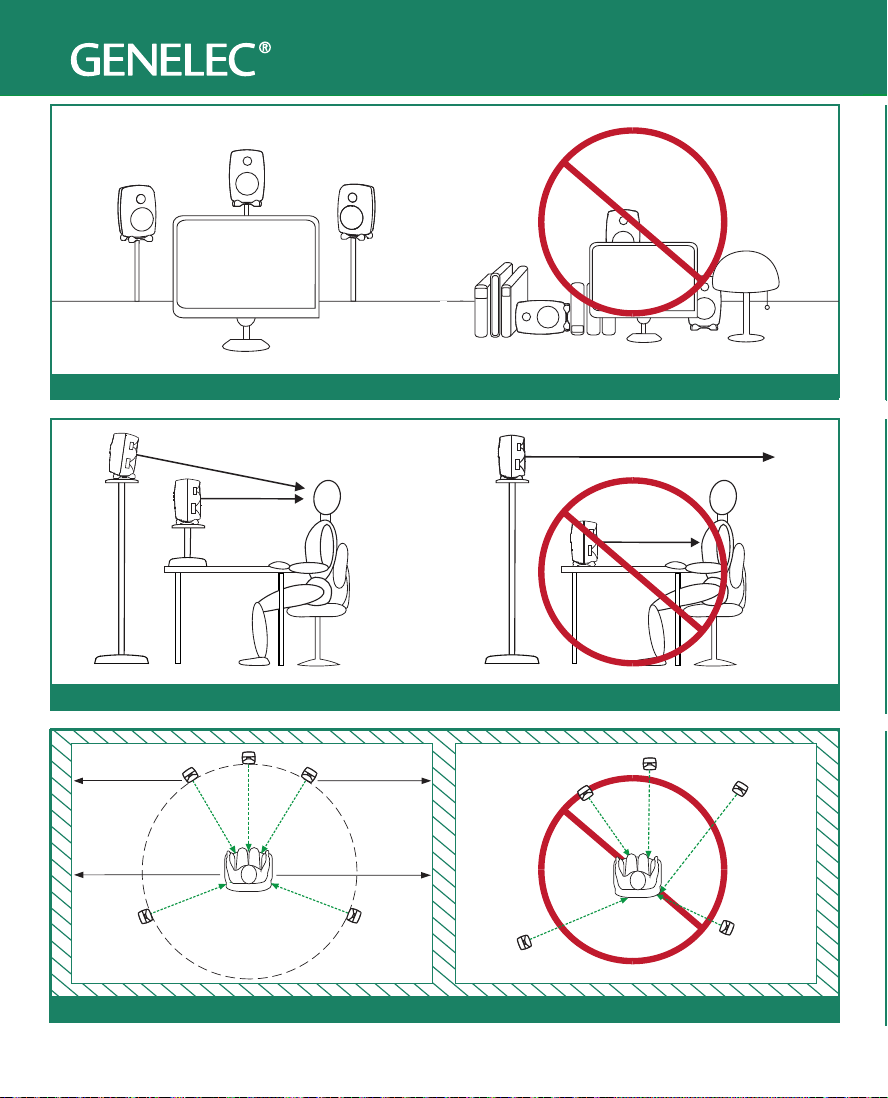
Speaker Angle
L
R
C
LS
RS
30˚
110˚
LS
RS
L
R
C
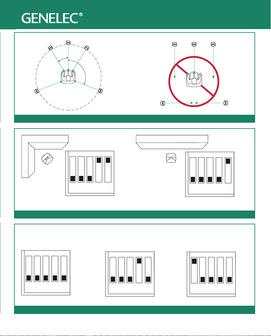
Suggested Tone Control Settings
Using Tone Controls
Against a wall
Corner
ON
OFF
1 2 3 4 5
-6 dB Bass Tilt
ON
OFF
-4 dB Bass Tilt
ON
OFF
TONE CONTROL
Free standing in a damped room Free standing in a reverberant room
ON
OFF
Desktop control
ON
OFF
-2 dB Bass Tilt
Nearfield or console
bridge setting
1 2 3 4 5
1 2 3 4 5
TONE CONTROL
1 2 3 4 5
TONE CONTROL
1 2 3 4 5
Quick setup guide 8030
L
A A
C
R
Speaker Placement
Vertical Angle
L
C
R
B
LS
B
RS
Symmetry of Room Installation
LS
RS
Page 3
Quick setup guide 8030
LS
Corner
C
L
30˚
R
110˚
RS
L
LS
C
R
RS
Speaker Angle
Against a wall
1 2 3 4 5
-6 dB Bass Tilt
ON
OFF
1 2 3 4 5
-4 dB Bass Tilt
ON
OFF
Using Tone Controls
Free standing in a damped room Free standing in a reverberant room
TONE CONTROL
1 2 3 4 5
ON
OFF
TONE CONTROL
1 2 3 4 5
-2 dB Bass Tilt
ON
OFF
Suggested Tone Control Settings
Nearfield or console
bridge setting
TONE CONTROL
1 2 3 4 5
Desktop control
ON
OFF
Page 4

General description
The bi-amplied GENELEC 8030C is a two way
active monitoring loudspeaker designed to be small
but still have high output, low coloration, and broad
bandwidth.
The 8030C is ideal for near eld monitoring,
mobile vans, broadcast and TV control rooms,
surround sound systems, home studios,
multimedia applications and also for use with
computer soundcards. As an active loudspeaker,
it contains drivers, power amplifiers, active
crossover filters and protection circuitry. The
MDE™ (Minimum Diffraction Enclosure™)
loudspeaker enclosure is made of die-cast
aluminium and shaped to reduce edge diraction.
Combined with the advanced Directivity Control
WaveguideTM (DCWTM), this design provides
excellent frequency balance in dicult acoustic
environments. If necessary, the bass response
of the 8030C can be extended with a suitable
Genelec subwoofer.
Positioning the loudspeaker
Each 8030C monitor is supplied with an integrated
amplifier unit, mains cable and an operating
manual. After unpacking, place the loudspeaker in
its required listening position, taking note of the line
of the acoustic axis. The axes of all loudspeakers
should converge at ear height at the listening
position (see Figure 1).
8030C
Active Monitoring System
an unearthed mains supply or using an unearthed
mains cable.
Audio input is via a 10 kOhm balanced female
XLR connector labelled “INPUT”. An unbalanced
source may be used as long as pin 3 is grounded
to pin 1 at the unbalanced source connector (see
Figure 2).
Once the connections have been made, the
loudspeakers are ready to be switched on.
ISSTM autostart function
The automatic power saving function ISS (Intelligent
Signal Sensing) can be activated by setting the
“ISS” switch on the back panel to “ON.” Automatic
powering down to standby mode happens after a
certain time when playback has ended. The power
consumption in standby mode is typically less than
0.5 watts. Playback will automatically resume once
an input signal is detected from the source.
There is a slight delay in the automatic powering
up. If this is undesirable, the ISSTM function can
be disabled by setting the “ISS” switch on the
back panel to “OFF.” In this mode, the monitor is
powered on and o using the power switch on the
back panel.
Connections
Connect the audio cables first and the mains
power cables only after you have completed the
audio cabling. Do not connect the loudspeaker to
4 English
Setting the sensitivity control
The input sensitivity of the loudspeaker can be
matched to the output of the audio signal source by
adjusting the sensitivity control on the back panel.
Page 5
> 0,7 m
ADJUSTMENT
ACOUSTIC
190 mm
AXIS
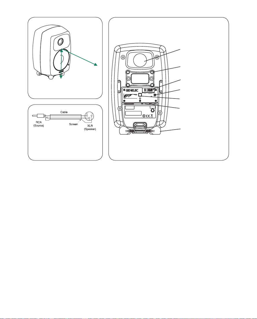
Figure 1: Location of the acoustic
axis
Figure 2: Type of cable needed if
unbalanced source is used (ex-
ample shown is RCA output to the
XLR input)
REFLEX PORT
THREADS FOR
CEILING AND
WARNING:ELECTRICSHOCK HAZARD.DONOTOPEN. DONOT
SUBJECTTOWATERORMOISTURE. NOUSERSERVICEABLE
PARTSINSIDE.REFERSERVICINGTO QUALIFIEDPERSONNEL.
USEEARTHEDMAINS CONNECTIONONLY.
AVERTISSEMENT:RISQUEDECHOCÉLECTRIQUE.NE PAS
OUVRIR.NEPAS EXPOSERÀL'EAUOUL'HUMIDITÉ.AUCUN
COMPOSANTÀL'INTÉRIEURREMPLAÇABLEPARL'UTILISATEUR.
ADRESSERTOUTERÉPARATIONÀUNPERSONNEL QUALIFIÉ.
CETAPPAREILDOITÊTRE RACCORDÉÀLATERRE.
LAITEONLIITETTÄVÄSUOJAKOSKETTIMILLAVARUSTETTUUN
PISTORASIAAN.
APPARATETMÅTILKOPLESJORDET STIKKONTAKT.
APPARATENSKALLANSLUTASTILLJORDATUTTAG.
ALLOFF
0
-2
BASS
-4
TILT
-6
DESKTOP
BASS
ROLL-OFF
16020 20k
1k
Frequency(Hz)
MAINSINPUT
50/60Hz60W
100- 240V~
SERIALNUMBER
Thisdevicecomplies withFCCPart15and Canadian
ICES-003radiofrequency ClassBemissionrequirements.
Refertooperating manualforfull information.
TREBLE
TILT
3k
8030CBI-AMPLIFIED
MONITORINGSYSTEM
MADEINFINLAND
ON
OFF
www.genelec.com
292-8030W
-6
+6
ISS
-3
-2dB
-4dB
+4
0
+2
INPUTdBu
PRODUCING
100dBSPL(1m)
TREBLETILT-2dB
BASSTILT
BASS ROLL-OFF-4dB
DESKTOP160Hz-4dB
ANALOG
IN
231
-GND
+
IN
292-8030CT
WALL MOUNTS
TONE CONTROLS
SENSITIVITY
POWER SWITCH
CONNECTOR PANEL
(HORIZONTAL)
Iso-Pod™TABLE
STAND
Figure 3: Control and connector layout on the rear panel
of the 8030C.
Setting the tone controls
The frequency response of the 8030C can be
adjusted to match the acoustic environment by
setting the tone control switches on the rear panel.
The controls are “Desktop”, “Treble Tilt”, “Bass Tilt”
and “Bass Roll-O”. An acoustic measuring system
is recommended for analyzing the eects of the
adjustments, however, careful listening with suitable
test recordings can also lead to good results if a
test system is not available. Table 1 shows some
typical settings in various situations. Figure 4 shows
the eect of the controls on the anechoic response.
Desktop
The desktop low frequency control (Switch 1)
attenuates the bass frequencies around 160 Hz by
4 dB. This feature is designed to compensate for
the boost often occurring at this frequency range
when the loudspeaker is placed upon a meter
bridge, table or similar reective surface.
Treble Tilt
Treble Tilt (switch 2) attenuates the treble response
above 4 kHz by 2 dB, which can be used for
smoothening down an excessively bright sounding
system.
Bass Roll-O
Bass Roll-O (switch 3) activates a -4 dB lter to
the lowest bass frequencies (55 Hz). This can be
used for compensating excessively heavy bass
reproduction typically caused by loudspeaker
placement near room boundaries.
English 5
Page 6

Loudspeaker Mounting Position Desktop Treble Tilt Bass Tilt Bass Roll-O
Flat anechoic response OFF OFF OFF OFF
Free standing in a damped room OFF OFF OFF OFF
Free standing in a reverberant room OFF OFF -2 dB OFF
Near eld or console bridge ON OFF OFF OFF
Near to a wall OFF OFF -4 dB OFF
On a desk ON OFF -2 dB OFF
Table 1: Suggested tone control settings for diering acoustical environments.
Bass Tilt
Bass Tilt oers three attenuation levels for the bass
response below 1 kHz, usually necessary when the
loudspeakers are placed near room boundaries.
The attenuation levels are -2 dB (switch 4 “ON”), -4
dB (switch 5 “ON”) and -6 dB (both switches “ON”).
The factory setting for all tone controls is
“OFF” to give a at anechoic response. Always
start adjustment by setting all switches to “OFF”
position. Measure or listen systematically through
the dierent combinations of settings to nd the
best frequency balance.
Mounting considerations
Align the loudspeakers correctly
Always place the loudspeakers so that their
acoustic axes (see gure 1) are aimed towards the
listening position. Vertical placement is preferable,
as it minimises acoustical cancellation problems
around the crossover frequency.
Maintain symmetry
Check that the loudspeakers are placed
symmetrically and at an equal distance from the
listening position. If possible, place the system so
that the listening position is on the centerline of the
room and the loudspeakers are placed at an equal
distance from the centerline.
Minimise reections
Acoustic reflections from objects close to the
loudspeakers like desks, cabinets, computer
monitors etc. can cause unwanted blurring of the
sound image. These can be minimised by placing
the loudspeaker clear of reflective surfaces. For
instance, putting the loudspeakers on stands behind
and above the mixing console usually gives a better
result than placing them on the meter bridge.
Minimum clearances
Sucient cooling for the amplier and functioning
of the reflex port must be ensured if the
loudspeaker is installed in a restricted space such
as a cabinet or integrated into a wall structure.
The surroundings of the loudspeaker must always
be open to the listening room with a minimum
clearance of 5 centimeters (2”) behind, above
and on both sides of the loudspeaker. The space
adjacent to the amplier must either be ventilated
or suciently large to dissipate heat so that the
ambient temperature does not rise above 35
degrees Celsius (95°F).
6 English
Page 7

Mounting options
The 8030C oers several mounting options: The
Iso-Pod™ (Isolation Positioner/Decoupler™)
vibration insulating table stand allows tilting of the
loudspeaker for correct alignment of the acoustic
axis. The stand can be attached to three mounting
points allowing vertical and symmetrical horizontal
positioning. On the base of the loudspeaker is
a 3/8” UNC threaded hole compatible with a
standard microphone stand. On the rear there are
two M6x10 mm threaded holes for Omnimount®
size 20.5 brackets.
Maintenance
No user serviceable parts are to be found within
the amplier unit. Any maintenance or repair of the
8030C unit should only be undertaken by qualied
service personnel.
Safety considerations
Although the 8030C has been designed in
accordance with international safety standards,
the following warnings and cautions should be
observed to ensure safe operation and to maintain
the loudspeaker under safe operating conditions:
• Servicing and adjustment must only be
performed by qualied service personnel. The
loudspeaker must not be opened.
• Do not use this product with an unearthed
mains cable as this may compromise electrical
safety.
• Do not expose the loudspeaker to water or
moisture. Do not place any objects lled with
liquid, such as vases on the loudspeaker or
near it.
• This loudspeaker is capable of producing
sound pressure levels in excess of 85 dB, which
may cause permanent hearing damage.
• Free ow of air behind the loudspeaker is
necessary to maintain sucient cooling. Do not
obstruct airow around the loudspeaker.
• Note that the amplier is not completely
disconnected from the AC mains service unless
the mains power cord is removed from the
amplier or the mains outlet.
Guarantee
This product is guaranteed for a period of two years
against faults in materials or workmanship. Refer to
supplier for full sales and guarantee terms.
Compliance to FCC rules
This device complies with part 15 of the FCC Rules. Operation
is subject to the following conditions:
This device may not cause harmful interference, and
This device must accept any interference received, including
interference that may cause undesired operation.
Note: This equipment has been tested and found to comply
with the limits for a Class B digital device, pursuant to part 15
of the FCC Rules. These limits are designed to provide rea-
sonable protection against harmful interference in a residential
installation. This equipment generates, uses and can radiate
radio frequency energy and, if not installed and used in accord-
ance with the instructions, may cause harmful interference to
radio communications. However, there is no guarantee that interference will not occur in a particular installation. If this equip-
ment does cause harmful interference to radio or television re-
ception, which can be determined by turning the equipment o
and on, the user is encouraged to try to correct the interference
by one or more of the following measures:
Reorient or relocate the receiving antenna.
Increase the separation between the equipment and receiver.
Connect the equipment into an outlet on a circuit dierent from
that to which the receiver is connected.
Consult the dealer or an experienced radio/TV technician for
help.
Modications not expressly approved by the manufacturer
could void the user’s authority to operate the equipment under
FCC rules.
English 7
Page 8

20
20k
50
100
200
500
1k 2k
5k
10k
Hz
Genelec Oy 8030 (dBr)vs freq(Hz) 20 Jan 17
0°
60°
15°
30°
45°
100
90
95
90
20
20k
50
100
200
500
1k 2k
5k
10k
Hz
Genelec Oy 8030 (dBr)vs freq(Hz) 19 Jan 17
80
85
90
BASS ROLL-OFF
TREBLE TILT
BASS TILT
80
85
90
DESKTOP
d
B
85
r
80
A
Figure 4. The curves
show the effect of the
“Bass Tilt”, “Treble Tilt”
and “Bass Roll-Off”
controls on the free eld
response of the 8030C
100
95
90
d
B
85
r
A
80
75
70
65
60
55
50
8 English
Figure 5. The upper
curve group shows the
horizontal directivity
characteristics of the
8030C measured at
1 m. The lower curve
shows the system's
power response.
Page 9

SYSTEM SPECIFICATIONS
Lower cut-off frequency, –6 dB: < 47 Hz
_____________________________________________
Upper cut-off frequency, –6 dB: > 25 kHz
_____________________________________________
Accuracy of frequency response:
54 Hz – 20 kHz (± 2.0 dB)
_____________________________________________
Maximum short term sine wave acoustic output on axis
in half space, averaged from 100 Hz to 3 kHz:
@ 1 m > 104 dB SPL
_____________________________________________
Maximum long term RMS acoustic output in same
conditions with IEC weighted noise (limited by driver unit
protection circuit): @ 1 m > 96 dB SPL
_____________________________________________
Maximum peak acoustic output per pair @ 1 m distance
with music material: > 110 dB
_____________________________________________
Self generated noise level in free field @ 1 m on axis:
< 5 dB (A-weighted)
_____________________________________________
Harmonic distortion at 85 dB SPL @ 1 m on axis:
Freq: 50…100 Hz < 2 %
>100 Hz < 0.5 %
_____________________________________________
Drivers: Bass 130 mm (5 in) cone
Treble 19 mm (3/4 in) metal dome
_____________________________________________
Weight: 5.0 kg (11 lb)
_____________________________________________
Dimensions: Height 299 mm (1113/16 in)
(including Iso-Pod™ table stand)
Height 285 mm (111/4 in)
(without Iso-Pod™ table stand)
Width 189 mm (77/16 in)
Depth 178 mm (7 in)
CROSSOVER SECTION
Connector: Input: XLR female, balanced 10 kOhm,
pin 1 gnd, pin 2 +, pin 3 -
_____________________________________________
Input level for 100 dB SPL output at 1 m: -6 dBu
_____________________________________________
Input sensitivity control range relative to max output:
-12 dB (Constantly variable)
_____________________________________________
Crossover frequency, Bass/Treble: 3.0 kHz
_____________________________________________
Treble Tilt control operating range:
0 to –2 dB @ 15 kHz
_____________________________________________
Bass Roll-Off control: –4 dB step @ 55 Hz
_____________________________________________
Bass Tilt control operating range in –2 dB steps:
0 to –6 dB @ 100 Hz
_____________________________________________
Desktop control: –4 dB @ 160 Hz
_____________________________________________
The ‘CAL’ position is with all tone controls set to ‘off’
and the input sensitivity control to maximum (fully
clockwise).
AMPLIFIER SECTION
Bass amplifier output power: 50 W
Treble amplifier output power: 50 W
Long term output power is limited by driver unit
protection circuitry.
_____________________________________________
Amplifier system distortion at nominal output:
THD < 0.05 %
_____________________________________________
Mains voltage: 100-240 V AC 50-60 Hz
Voltage operating range: ±10 %
Power consumption:
Idle 3 W
Standby in ISS mode <0.5 W
Full output 60 W
English 9
Page 10

8030C
Aktiivikaiutin
Yleistä
GENELEC 8030C on pienikokoinen, mutta erittäin
suorituskykyinen aktiivikaiutin. Se soveltuu lähi-
kenttämonitoriksi äänitysstudioihin, ulkolähetys-
autoihin, radio- ja TV-lähetysten äänen tarkkailuun,
julkisiin tiloihin, installaatioihin, kotistudioihin, mul-
timediatuotantoon, tietokoneiden audiojärjestelmiin
ja kotiteattereihin. Kaiutinkoteloon on integroitu
päätevahvistimet, säädettävän aktiivisen jakosuoti-
men ja kaiutinelementtien ylikuormitussuojauspiirit.
Uusi Minimum Diffraction Enclosure™ (MDE™)-
kotelorakenne ja edelleen kehitetty Directivity Cont-
rol Waveguide™ (DCW™)-suuntain takaavat tasa-
painoisen toiston vaikeissakin akustisissa ympäris-
töissä. Tarvittaessa 8030C:n bassotoistoa voidaan
tukea sopivalla Genelec-subwooferilla.
Liitännät
Kaiuttimien mukana toimitetaan suojamaadoitetut
verkkovirtajohdot. Kytke virtajohdot viimeisenä,
vasta kun kaikki signaalijohdot ovat paikoillaan. Älä
10 Suomi
kytke kaiutinta suojamaadoittamattomaan pistora-
siaan.
Audiosignaalia varten kaiuttimissa on balansoitu
XLR-liitin, ”INPUT”. Äänilähteeltä tuleva signaalijohto kytketään ”INPUT”-liittimeen. Ellei ääni-
lähteessä ole balansoitua antoliitäntää, voidaan
käyttää kuvan 2 mukaisesti kytkettyä RCA/XLR
signaalijohtoa.
Genelec 8030C-aktiivikaiuttimet saa kytkeä
ainoastaan linjatasoista signaalia antavaan ääni-
lähteeseen, ei milloinkaan päätevahvistimen tai
integroidun vahvistimen kaiutinliittimiin.
Kytke virta päälle vasta kun kaikki liitännät on
tehty.
Automaattinen virrankytkentä
(ISSTM Autostart)
Kaiuttimessa on signaalin tunnistava automaattinen
virrankytkentä, joka kytkee sen toimintaan heti kun
kaiuttimeen tulee äänisignaali. Vastaavasti kaiutin
menee automaattisesti valmiustilaan, kun signaa-
Page 11

> 0,7 m
ASTESÄÄTIMET
AKUSTINEN
190 mm
AKSELI
Kuva 1: Kaiuttimen akustisen akselin
sijainti.
Kuva 2: Balansoimattomaan RCA-
liittimeen liitettäessä tarvittavan
välikaapelin kytkentä.
WARNING:ELECTRICSHOCK HAZARD.DONOTOPEN. DONOT
SUBJECTTOWATERORMOISTURE. NOUSERSERVICEABLE
PARTSINSIDE.REFERSERVICINGTO QUALIFIEDPERSONNEL.
USEEARTHEDMAINS CONNECTIONONLY.
AVERTISSEMENT:RISQUEDECHOCÉLECTRIQUE.NE PAS
OUVRIR.NEPAS EXPOSERÀL'EAUOUL'HUMIDITÉ.AUCUN
COMPOSANTÀL'INTÉRIEURREMPLAÇABLEPARL'UTILISATEUR.
ADRESSERTOUTERÉPARATIONÀUNPERSONNEL QUALIFIÉ.
CETAPPAREILDOITÊTRE RACCORDÉÀLATERRE.
LAITEONLIITETTÄVÄSUOJAKOSKETTIMILLAVARUSTETTUUN
PISTORASIAAN.
APPARATETMÅTILKOPLESJORDET STIKKONTAKT.
292-8030W
APPARATENSKALLANSLUTASTILLJORDATUTTAG.
ON
OFF
-6
www.genelec.com
+6
ISS
-3
-2dB
-4dB
+4
0
+2
INPUTdBu
PRODUCING
100dBSPL(1m)
TREBLETILT-2dB
BASSTILT
BASS ROLL-OFF-4dB
DESKTOP160Hz-4dB
ANALOG
IN
231
-GND
+
IN
292-8030CT
ALLOFF
0
-2
BASS
-4
TILT
-6
DESKTOP
BASS
ROLL-OFF
16020 20k
1k
Frequency(Hz)
MAINSINPUT
50/60Hz60W
100- 240V~
SERIALNUMBER
Thisdevicecomplies withFCCPart15and Canadian
ICES-003radiofrequency ClassBemissionrequirements.
Refertooperating manualforfull information.
TREBLE
TILT
3k
8030CBI-AMPLIFIED
MONITORINGSYSTEM
MADEINFINLAND
Kuva 3: 8030C:n takapaneeli.
REFLEKSIPUTKI
KIERTEET SEINÄJA KATTOTELINEILLE
TAAJUUSV
HERKKYYDEN SÄÄTÖ
VIRTAKYTKIN
LIITINPANEELI
Iso-Pod™
PÖYTÄJALUSTA
lin päättymisestä on kulunut noin tunti. Valmiustilassa kaiuttimien tehonkulutus on alle 0,5 W. Tämä
toiminto aktivoidaan kääntämällä takapaneelissa
oleva ”ISS”-kytkin asentoon ”ON.”
Automaattisessa käynnistymisessä on pieni vii-
ve. Jos tämä ei ole hyväksyttävää, automaattinen
virrankytkentä voidaan poistaa toiminnasta kään-
tämällä ”ISS”-kytkin kaiuttimen takapaneelissa
asentoon ”OFF.” Tällöin kaiutin käynnistyy ja sammuu ainoastaan virtakytkintä käyttäen.
Herkkyyden säätö
Kaiuttimen ottoliitännän herkkyys (äänenvoimak-
kuus) voidaan säätää äänilähteen antosignaalin
tasoon sopivaksi takapaneelissa olevalla sääti-
mellä.
Taajuusvastesäätöjen käyttö
Kaiuttimen taajuusvastetta voidaan muokata kuun-
telutilan akustisista ominaisuuksista ja kaiuttimien
sijoituksesta johtuvien toistovirheiden kompensoi-
miseksi. Säätö tehdään kaiuttimen takapaneelissa
olevien ”Desktop”, “Treble Tilt”-, “Bass Roll-O”- ja
“Bass Tilt”-kytkimien avulla. Kaikki säädöt asetetaan tehtaalla asentoon “OFF”, mikä antaa tasaisen
taajuusvasteen kaiuttomassa tilassa. Säätöjen vaikutus toistovasteeseen on esitetty kuvassa 4.
Suosittelemme akustisen mittausjärjestelmän
käyttöä kaiuttimien säätämisessä. Ellei tällaista
ole käytettävissä, säätö voidaan tehdä myös kor-
vakuulolta sopivia testiäänitteitä ja -signaaleja
hyväksikäyttäen. Taulukko 1 sisältää muutamia
suuntaa-antavia säätöesimerkkejä. Kaiuttimien
Suomi 11
Page 12

Kaiuttimien sijoitus Desktop Treble Tilt Bass Tilt Bass roll–o
Kaiuttomassa tilassa OFF OFF OFF OFF
Vapaasti seisovana vaimennetussa tilassa OFF OFF OFF OFF
Vapaasti seisovana kaikuvassa tilassa OFF OFF -2 dB OFF
Lähikentässä, äänipöydän mittarisillalla ON OFF OFF OFF
Lähellä seinää OFF OFF -6 dB ON
Pöydällä ON OFF -2 dB OFF
Taulukko 1: Suositeltavat taajuusvastesäätimien (tone control) asetukset kaiuttimien sijoituksen mukaan
sijoitus ja akustinen ympäristö vaikuttaa ratkaise-
vasti säätötarpeeseen, joten säätöön kannattaa
ryhtyä vasta kun kuuntelutilan järjestys on saatu
lopulliseen muotoonsa.
Desktop 160 Hz
Desktop-säätö aktivoi 4 dB:n vaimennuksen 160
Hz:n kohdalle kompensoimaan äänipöydän, pöytä-
tason tai muun kaiuttimen ja kuuntelijan välissä sijait-
sevan vaakasuoran tason aiheuttaman korostuman.
Treble Tilt
Treble Tilt-säätö (kytkin 2) vaimentaa kaiuttimen dis-
kanttitoistoa 4 kHz:n yläpuolella 2 dB, mitä voidaan
käyttää liian kirkkaalta tuntuvan toiston korjaami-
seen.
Bass Roll-O
Bass Roll-O-säätö kytkee -4 dB:n vaimennuksen
matalille bassotaajuuksille. Tätä voidaan käyttää
esimerkiksi kaiutinta lähellä olevien rajapintojen
aiheuttaman korostuneen bassotoiston kompen-
soimiseen.
Bass Tilt
Bass Tilt-säädön avulla voidaan vaimentaa kaiut-
timen bassotoistoa 1 kHz:n alapuolella. Tämä on
usein tarpeen, kun kaiutin sijoitetaan lähelle seinää
tai muuta rajapintaa. Vaimennustasoja on kolme: -2
dB (kytkin 4 “ON”), -4 dB (kytkin 5 “ON”) ja -6 dB
(kytkimet 4 ja 5 “ON”).
Kaiuttimien sijoitus
Kohdista kuuntelupisteeseen
Suuntaa kaiuttimet kuuntelualueen keskipistee-
seen pään korkeudelle. Suuntaus on tehty oikein,
kun kaikkien kaiuttimien akustiset akselit (kuva 1)
leikkaavat kuuntelupisteessä. Kaiuttimet kannattaa
sijoittaa pystyasentoon, sillä se minimoi vaihevir-
heet jakotaajuudella.
Sijoita symmetrisesti
Sijoita kaiuttimet samalle etäisyydelle kuuntelu-
pisteestä ja mahdollisimman symmetrisesti sekä
toistensa, että huoneen rajapintojen suhteen. Tämä
toteutuu, kun kuuntelupiste on huoneen keskilin-
jalla ja kaiuttimet sijoitetaan symmetrisesti keskilin-
jan suhteen.
Minimoi heijastukset
Kaiuttimen lähellä sijaitsevista esineistä ja pinnoista
tulevat akustiset heijastukset voivat aiheuttaa tois-
12 Suomi
Page 13

ton värittymistä ja sumentaa äänikuvaa. Tämä
kannattaa ottaa huomioon kaiuttimia sijoitettaessa
ja mahdollisuuksien mukaan siirtää heijastuksia
aiheuttavat tietokoneen näytöt, kaapit tms. pois
kaiuttimien läheltä ja sijoittaa kaiuttimet niin, että ne
ovat kauempana jäljelle jäävistä heijastuksia aiheut-
tavista pinnoista. Tarkkailukaiuttimia ei esimerkiksi
kannata sijoittaa äänipöydän päälle, vaan riittävän
korkeille lattiajalustoille äänipöydän taakse, josta ne
voidaan suunnata alas äänitarkkailijaa kohti.
Vähimmäisetäisyydet
Vahvistimien jäähdytyksen ja reeksiputken toimin-
nan takaamiseksi pitää kaiuttimien taakse, sivuille
ja päälle jäädä kuunteluhuoneeseen avautuva,
vähintään viiden senttimetrin vapaatila. Kaiutinta
ei saa käyttää tilassa, jonka lämpötila on yli 35° C.
Virheellisestä käytöstä saattaa kuitenkin seurata
vaaratilanne, joten seuraavia ohjeita on aina nou-
datettava:
• Laitetta ei saa asettaa alttiiksi kosteudelle
tai roiskevedelle. Se on tarkoitettu
käytettäväksi ainoastaan kuivassa
huonetilassa.
• Huolto- ja korjaustoimia saa suorittaa vain
valmistajan valtuuttama huoltohenkilöstö.
• Älä avaa kaiutinkoteloa tai irrota laitteesta
mitään osia.
• Laitteen saa kytkeä ainoastaan
maadoitettuun pistorasiaan.
• Huomaa, että vahvistin ei ole täysin
jännitteetön ellei virtajohtoa ole irrotettu
pistokkeesta.
Pöytäjalusta ja kiinnitysmahdollisuudet
Kaiuttimien mukana toimitettava Isolation Positioner/Decoupler™ (Iso-Pod™)-jalusta mahdollistaa kaiuttimen kallistamisen ylä- tai alaviistoon.
Jalusta voidaan kiinnittää myös kaiutinkotelon
pitkille sivuille, jos kaiuttimet halutaan sijoittaa
vaaka-asentoon. (kuva 3).
Genelec 8030C voidaan kiinnittää Omnimount®
Series 20.5-kaiutintelineisiin kaiutinkotelon takaseinässä olevien M6x10-mutterikierteiden avulla.
Kotelon pohjassa on 3/8
kaiutin voidaan kiinnittää mikrofonitelineeseen.
Tutustu Genelecin ajan tasalla olevaan lisäva-
rustevalikoimaan nettisivullamme.
in
UNC-mutterikierre, jolla
Turvallisuusohjeita
Genelec-aktiivikaiuttimet on suunniteltu ja valmis-
tettu täyttämään kansainväliset turvallisuusnormit.
VAROITUS!
Genelec 8030C-aktiivikaiuttimet pystyvät tuotta-
maan yli 85 desibelin äänenpaineen, mikä voi aihe-
uttaa pysyvän kuulovaurion.
Huolto
Kaikki huolto- ja korjaustoimet on annettava val-
mistajan tai valmistajan valtuuttaman huoltohenki-
löstön suoritettaviksi. Älä avaa laitetta itse.
Takuu
Genelec Oy antaa tuotteilleen kahden vuoden
takuun ostopäivästä lukien. Takuu kattaa valmistusvirheet ja materiaaliviat.
Suomi 13
Page 14

90
20
20k
50
100
200
500
1k 2k
5k
10k
Hz
Genelec Oy 8030 (dBr)vs freq(Hz) 19 Jan 17
80
85
90
BASS ROLL-OFF
TREBLE TILT
BASS TILT
80
85
90
DESKTOP
20
20k
50
100
200
500
1k 2k
5k
10k
Hz
Genelec Oy 8030 (dBr)vs freq(Hz) 20 Jan 17
0°
60°
15°
30°
45°
100
90
95
d
B
85
r
80
A
Kuva 4: Taajuusvastesäätimien vaikutus 8030C:n
toistovasteeseen.
100
95
90
d
B
85
r
A
80
75
70
65
60
55
50
14 Suomi
Kuva 5: Ylemmät käyrät
esitttävät 8030C:n taajuusvasteen eri kulmista
mitattuna (kaiutin pystyasennossa, mittau-
setäisyys 1 m). Alempi
käyrä on kaiuttimen
tehovaste.
Page 15

TEKNISET TIEDOT
Alarajataajuus, –6 dB: < 47 Hz
_____________________________________________
Ylärajataajuus, –6 dB: > 25 kHz
_____________________________________________
Taajuusvaste vapaakentässä:
54 Hz – 20 kHz (± 2,0 dB)
_____________________________________________
Hetkellinen maksimiäänenpaine mitattuna sinisignaalilla
puoliavaruuteen. Keskiarvo taajuusalueella
100 Hz...3 kHz: @ 1 m > 104 dB SPL
_____________________________________________
Suurin jatkuva (RMS) äänenpaine IEC-painotetulla
kohinalla mitattuna (elementtien suojapiirin rajoittama):
@ 1 m > 96 dB SPL
_____________________________________________
Kaiutinparin tuottama äänenpaineen huippuarvo (peak)
musiikkimateriaalilla 1 metrin mittausetäisyydellä:
> 110 dB
_____________________________________________
Akustinen pohjakohinataso 1 m:n etäisyydellä:
< 5 dB (A-painotettu)
_____________________________________________
Harmoninen särö 85 dB 1 m mittausakselilla:
Taajuus: 50…100 Hz < 2 %
>100 Hz < 0,5 %
_____________________________________________
Kaiutinelementit:
Basso 130 mm (5 in) kartio
Diskantti 19 mm (3/4 in) metallikalotti
_____________________________________________
Paino: 5,0 kg (11 lb)
_____________________________________________
Mitat
Korkeus 299 mm (1113/16 in)
(mukaanlukien Iso–Pod™ pöytäjalusta)
Korkeus 285 mm (111/4 in)
(ilman Iso–Pod™ pöytäjalustaa)
Leveys 189 mm (77/16 in)
Syvyys 178 mm (7 in)
:
JAKOSUODIN
Liittimet: Input (ottoliitin): XLR naaras, balansoitu
10 kOhm, napa 1 maa, napa 2 +, napa 3 –
_____________________________________________
Tarvittava signaalitaso 100 dB SPL äänenpaineen
tuottamiseen 1 m:n mittausetäisyydellä: -6 dBu
_____________________________________________
Herkkyyssäätimen vaikutus (vaimennus
maksimiäänenpaineesta): -12dB (liukuva)
_____________________________________________
Jakotaajuus: 3,0 kHz
_____________________________________________
Treble Tilt-säädön vaikutus: -2 dB @ 15 kHz
_____________________________________________
Bass Roll-Off-säädön vaikutus: -4 dB @ 55 Hz
_____________________________________________
Bass Tilt-säädön vaikutus: 0, -2, -4 tai -6 dB @ 100 Hz
_____________________________________________
Desktop-säädön vaikutus: -4 dB @ 160 Hz
_____________________________________________
Säätimien ‘CAL’ asento: Kaikki tajuusvastesäätimet
asennossa “o” ja herkkyyden säätö maksimiasennossa.
VAHVISTIMET
Bassovahvistimen teho: 50 W
Diskanttivahvistimen teho: 50 W
Kaiutinelementtien suojauselektroniikka rajoittaa
vahvistimien jatkuvaa tehoa
_____________________________________________
Vahvistimien särö nimellisteholla:
THD < 0,05 %
____________________________________________
Käyttöjännite: 100-240 V AC 50-60 Hz
Sallittu jännitteen vaihtelu: ±10 %
Tehonkulutus:
Ilman kuormaa 3 W
Valmiustilassa (ISS) <0,5 W
Maksimikuormalla 60 W
.
Suomi 15
Page 16

International enquiries
Genelec, Olvitie 5
FI 74100, Iisalmi, Finland
Phone +358 17 83881
Fax +358 17 812 267
Email genelec@genelec.com
In Sweden
Genelec Sverige
Ellipsvägen 10B
Box 2036,
S-127 02 Skärholmen
Phone +46 8 449 5220
Fax +46 8 708 7071
Email info@genelec.com
In the USA
Genelec, Inc., 7 Tech Circle
Natick, MA 01760, USA
Phone +1 508 652 0900
Fax +1 508 652 0909
Email genelec.usa@genelec.com
In China
Beijing Genelec Audio Co.Ltd
Room 101, 1st Floor,
Building 71 B33
Universal Business Park
No.10 Jiuxianquiao Road
Chaoyang District
Beijing China
Post Code 100015
Phone +86 010 58697915/13
Email genelec.china@genelec.com
www.genelec.com
Genelec Document D0036R001e Copyright Genelec Oy 1.2017. All data subject to change without prior notice
 Loading...