

Page 1
8030B
Operating Manual 2-7
Betriebsanleitung 8-13
Manuel d’utilisation 14-19
Käyttöohje 20-25
Bruksanvisning 26-31
Page 2

8030B
Active Monitoring System
General description
The bi-amplified GENELEC 8030B is a two way
active monitoring loudspeaker designed to be small
but still have high output, low coloration, and broad
bandwidth.
The 8030B is ideal for near field monitoring,
mobile vans, broadcast and TV control rooms, surround sound systems, home studios, multimedia
applications and also for use with computer soundcards. As an active loudspeaker, it contains drivers, power amplifiers, active crossover filters and
protection circuitry. The MDE™ (Minimum Diffraction Enclosure™) loudspeaker enclosure is made
of die-cast aluminium and shaped to reduce edge
diffraction. Combined with the advanced Directivity Control WaveguideTM (DCWTM), this design
provides excellent frequency balance in difficult
acoustic environments. If necessary, the bass
response of the 8030B’s can be extended with a
suitable Genelec subwoofer.
Positioning the loudspeaker
Each 8030B monitor is supplied with an integrated amplifier unit, mains cable and an operating
manual. After unpacking, place the loudspeaker in
its required listening position, taking note of the line
of the acoustic axis. The axes of all loudspeakers
should converge at ear height at the listening position
(see Figure 1).
Connections
Before connecting up, ensure that the mains
switch is off and the volume control fully counterclockwise. These controls are located on the front
panel of the loudspeaker. Do not connect the loudspeaker to an unearthed mains supply or using an
unearthed mains cable.
Audio input is via a 10 kOhm balanced female
XLR connector labelled “INPUT”. An unbalanced
source may be used as long as pin 3 is grounded
to pin 1 at the unbalanced source connector (see
Figure 2).
The male XLR “OUTPUT” connector can be
used for daisy-chaining up to six 8030B’s together
or for connecting a Genelec 7050B subwoofer. The
volume control attenuates the signal on this output,
so the first “master” loudspeaker on a daisy-chain
can be used to adjust the level on the whole chain.
The volume controls on the “slave” loudspeakers
should be set fully clockwise.
Once the connections have been made, the
loudspeakers are ready to be switched on.
Autostart function
The signal sensing Autostart function of the loudspeakers powers them up when playback begins.
Automatic powering down of the loudspeakers
happens one hour after the playback has ended
and the loudspeakers go to standby mode. The
power consumption in standby mode is less than
2 English
Page 3
> 0,7 m
ACOUSTIC
190 mm
AXIS
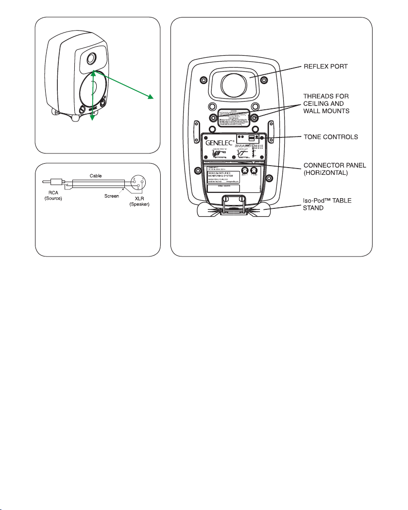
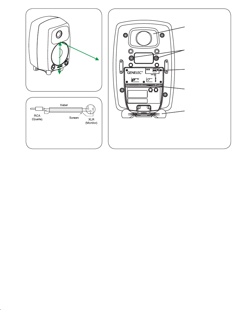
Figure 1: Location of the acoustic
axis
Figure 2: Type of cable needed if
unbalanced source is used (example shown is RCA output to the
XLR input)
Figure 3: Control and connector layout on the rear panel of
the 8030B.
0.5 watts. The loudspeakers will automatically and
rapidly start once an input signal is detected from
the source.
Setting the volume control
The input sensitivity of the loudspeaker can be
matched to the output of the audio signal source by
adjusting the volume control on the front panel.
Setting the tone controls
The frequency response of Genelec 8030B can
be adjusted to match the acoustic environment by
setting the tone control switches on the rear panel.
The controls are “Treble Tilt”, “Bass Tilt” and “Bass
Roll-Off”. An acoustic measuring system such as
WinMLS is recommended for analyzing the effects
of the adjustments, however, careful listening with
suitable test recordings can also lead to good
results if a test system is not available. Table 1
shows some typical settings in various situations.
Figure 4 shows the effect of the controls on the
anechoic response.
Treble Tilt
Treble Tilt (switch 1) attenuates the treble response
above 5 kHz by 2 dB, which can be used for smoothening down an excessively bright sounding system.
Bass Tilt
Bass Tilt offers three attenuation levels for the bass
response below 1 kHz, usually necessary when the
loudspeakers are placed near room boundaries.
The attenuation levels are -2 dB (switch 3 “ON”), -4
dB (switch 4 “ON”) and -6 dB (both switches “ON”).
English 3
Page 4
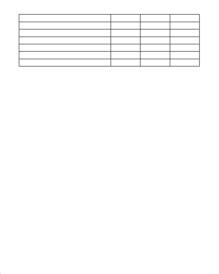
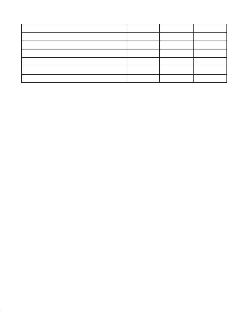
Loudspeaker Mounting Position Treble Tilt Bass Tilt Bass Roll-Off
Flat anechoic response OFF OFF OFF
Free standing in a damped room OFF OFF OFF
Free standing in a reverberant room OFF -2 dB OFF
Near field or console bridge OFF -4 dB OFF
Near to a wall OFF -6 dB OFF
With a 7050 subwoofer See above See above ON
Table 1: Suggested tone control settings for differing acoustical environments
Bass Roll-Off
Bass Roll-Off (switch 2) activates high-pass filtering at 85 Hz to complement the low-pass filter on a
Genelec 7050 subwoofer. This switch should always
be set to “ON” when using the 8030B with a 7050
subwoofer.
The factory setting for all tone controls is “OFF” to
give a flat anechoic response. Always start adjustment by setting all switches to “OFF” position. Measure or listen systematically through the different
combinations of settings to find the best frequency
balance.
Mounting considerations
Align the loudspeakers correctly
Always place the loudspeakers so that their acoustic axes (see figure 1) are aimed towards the listening position. Vertical placement is preferable, as it
minimises acoustical cancellation problems around
the crossover frequency.
Maintain symmetry
Check that the loudspeakers are placed symmetrically and at an equal distance from the listening
position. If possible, place the system so that the lis-
tening position is on the centerline of the room and
the loudspeakers are placed at an equal distance
from the centerline.
Minimise reflections
Acoustic reflections from objects close to the loudspeakers like desks, cabinets, computer monitors
etc. can cause unwanted blurring of the sound
image. These can be minimised by placing the loudspeaker clear of reflective surfaces. For instance,
putting the loudspeakers on stands behind and
above the mixing console usually gives a better
result than placing them on the meter bridge.
Minimum clearances
S
ufficient cooling for the amplifier and functioning of the reflex port must be ensured if the loudspeaker is installed in a restricted space such as a
cabinet or integrated into a wall structure. The surroundings of the loudspeaker must always be open
to the listening room with a minimum clearance of 5
centimeters (2”) behind, above and on both sides of
the loudspeaker. The space adjacent to the amplifier must either be ventilated or sufficiently large
to dissipate heat so that the ambient temperature
does not rise above 35 degrees Celsius (95°F).
4 English
Page 5

Mounting options
The 8030B offers several mounting options: The
Iso-Pod™ (Isolation Positioner/Decoupler™) vibration insulating table stand allows tilting the loudspeaker for correct alignment of the acoustic axis.
The stand can be attached to three mounting
points allowing vertical and symmetrical horizontal
positioning. On the base of the loudspeaker is a
3/8” UNC threaded hole compatible with a standard microphone stand. On the rear there are two
M6x10 mm threaded holes for Omnimount® size
20.5 brackets.
Maintenance
No user serviceable parts are to be found within
the amplifier unit. Any maintenance or repair of the
8030B unit should only be undertaken by qualified
service personnel.
Safety considerations
Although the 8030B has been designed in accordance with international safety standards, the following warnings and cautions should be observed
to ensure safe operation and to maintain the loudspeaker under safe operating conditions:
• Servicing and adjustment must only be
performed by qualified service personnel. The
loudspeaker must not be opened.
• Do not use this product with an unearthed
mains cable as this may compromise
electrical safety.
• Do not expose the loudspeaker to water or moisture. Do not place any objects filled with liquid,
such as vases on the loudspeaker or near it.
• This loudspeaker is capable of producing sound
pressure levels in excess of 85 dB, which may
cause permanent hearing damage.
• Free ow of air behind the loudspeaker is necessary to maintain sufficient cooling. Do not
obstruct airflow around the loudspeaker.
• Note that the amplifier is not completely disconnected from the AC mains service unless the
mains power cord is removed from the amplifier
or the mains outlet.
Guarantee
This product is guaranteed for a period of two years
against faults in materials or workmanship. Refer to
supplier for full sales and guarantee terms.
Compliance to FCC rules
This device complies with part 15 of the FCC Rules. Operation is
subject to the following conditions:
• This device may not cause harmful interference, and
• This device must accept any interference received,
including interference that may cause undesired operation.
Note: This equipment has been tested and found to comply with
the limits for a Class B digital device, pursuant to part 15 of the
FCC Rules. These limits are designed to provide reasonable protection against harmful interference in a residential installation.
This equipment generates, uses and can radiate radio frequency
energy and, if not installed and used in accordance with the instructions, may cause harmful interference to radio communications. However, there is no guarantee that interference will not
occur in a particular installation. If this equipment does cause
harmful interference to radio or television reception, which can
be determined by turning the equipment off and on, the user is
encouraged to try to correct the interference by one or more of
the following measures:
• Reorient or relocate the receiving antenna.
• Increase the separation between the equipment and
receiver.
• Connect the equipment into an outlet on a circuit different
from that to which the receiver is connected.
• Consult the dealer or an experienced radio/TV technician
for help.
Modifications not expressly approved by the manufacturer
could void the user’s authority to operate the equipment under
FCC rules.
English 5
Page 6
Genelec Oy 8030 (dBr) vs freq (Hz) 22 Jan 13
0°
60°
15°
30°
45°
100
90
95
95
20
50
1k 2k
10k
Genelec Oy 8030 (dBr) vs freq (Hz) 22 Jan 13
80
85
90
75
BASS ROLL-OFF
TREBLE TILT
BASS TILT
d
B
90
r
85
A
80
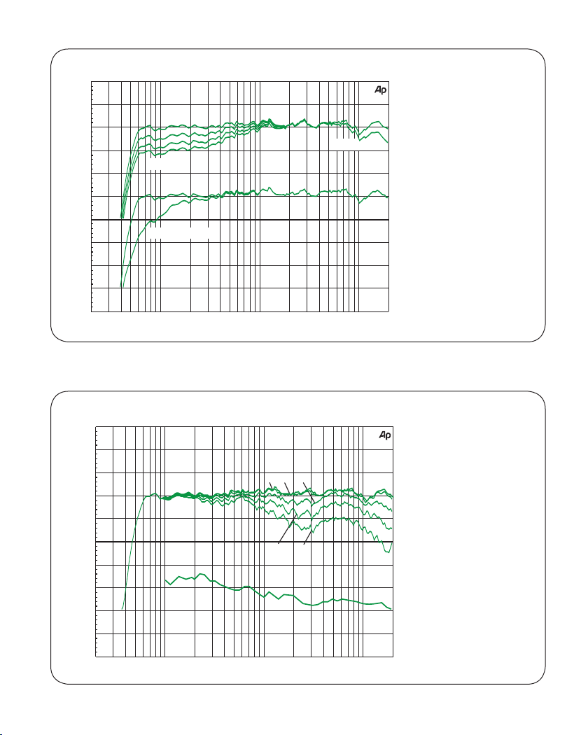
Figure 4. The curves
show the effect of the
“Bass Tilt”, “Treble Tilt”
and “Bass Roll-Off” controls on the free field response of the 8030B
100
200
500
100
95
90
d
B
85
r
A
80
75
70
65
60
55
50
20
100
200
50
500
1k 2k
6 English
5k
20k
Hz
Figure 5. The upper
curve group shows the
horizontal directivity
characteristics of the
8030B measured at
1 m. The lower curve
shows the system's
power response.
Hz
10k
20k
5k
Page 7
SYSTEM SPECIFICATIONS
Lower cut-off frequency, –3 dB: < 55 Hz
_____________________________________________
Upper cut-off frequency, –3 dB: > 21 kHz
_____________________________________________
Free field frequency response of system:
58 Hz – 20 kHz (± 2.0 dB)
_____________________________________________
Maximum short term sine wave acoustic output on axis in
half space, averaged from 100 Hz to 3 kHz:
@ 1 m > 100 dB SPL
@ 0.5 m > 106 dB SPL
_____________________________________________
Maximum long term RMS acoustic output in same
conditions with IEC weighted noise (limited by driver unit
protection circuit): @ 1 m > 97 dB SPL
_____________________________________________
Maximum peak acoustic output per pair on top of
console, @ 1 m distance with music material: > 108 dB
_____________________________________________
Self generated noise level in free field @ 1 m on axis:
< 10 dB (A-weighted)
_____________________________________________
Harmonic distortion at 85 dB SPL @ 1 m on axis:
Freq: 50…100 Hz < 2 %
>100 Hz < 0.5 %
_____________________________________________
Drivers: Bass 130 mm (5") cone
Treble 19 mm (3/4") metal dome
Both drivers are magnetically shielded
_____________________________________________
Weight: 5.6 kg (12.3 lb)
_____________________________________________
Dimensions: Height 299 mm (1113/16”)
(including Iso-Pod™ table stand)
Height 285 mm (111/4”)
(without Iso-Pod™ table stand)
Width 189 mm (77/16")
Depth 178 mm (7”)
CROSSOVER SECTION
Connectors: Input: XLR female, balanced 10 kOhm,
pin 1 gnd, pin 2 +, pin 3 Output: XLR male, balanced 100 Ohm,
pin 1 gnd, pin 2 +, pin 3 -
_____________________________________________
Input level for 100 dB SPL output at 1 m:
-6 dBu at volume control max
_____________________________________________
Volume control range: -80 dB relative to max output
Output signal level is 0 dB relative to input signal level
but adjustable by volume control
_____________________________________________
Crossover frequency, Bass/Treble: 3.0 kHz
_____________________________________________
Treble Tilt control operating range:
0 to –2 dB @ 15 kHz
_____________________________________________
Bass Roll-Off control operating in a –6 dB step @ 85 Hz
(to be used in conjunction with a 7050B subwoofer)
_____________________________________________
Bass Tilt control operating range in –2 dB steps:
0 to –6 dB @ 100 Hz
_____________________________________________
The ‘CAL’ position is with all tone controls set to ‘off’ and
the input sensitivity control to maximum (fully clockwise).
AMPLIFIER SECTION
Bass amplifier output power with an 8 Ohm load: 40 W
Treble amplifier output power with an 8 Ohm load: 40 W
Long term output power is limited by driver unit protection
circuitry.
_____________________________________________
Amplifier system distortion at nominal output:
THD < 0.05 %
SMPTE-IM < 0.05 %
CCIF-IM < 0.05 %
DIM 100 < 0.05 %
_____________________________________________
Signal to Noise ratio, referred to full output:
Bass > 100 dB
Treble > 100 dB
_____________________________________________
Mains voltage: 100, 120, 220 or 230 V
according to region
Voltage operating range: ±10 %
Power consumption:
Idle 10 W
Standby <0,5 W
Full output 80 W
English 7
Page 8

Betriebsanleitung
8030B
Aktives Monitorsystem
Einleitende Beschreibung
Der aktive Zweiweg-Monitor GENELEC 8030B ist ein
extrem kompakt gebauter Lautsprecher für den Einsatz
als Nahfeldmonitor, Ü-Wageneinsatz, Rundfunk- und
TV-Senderegie, Surroundsysteme, Homerecording,
Multimediaanwendungen und auch für den direkten
Anschluss an Soundkarten. Als aktiver Lautsprecher
enthält der 8030B neben den Lautsprecherchassis
auch Endstufen, aktive Frequenzweiche und Schutzschaltungen. Das MDE™-Lautsprechergehäuse (Minimum Diffraction Enclosure™) besteht aus AluminiumDruckguss und ist so geformt, dass die Schallbeugung
an den Gehäusekanten stark reduziert wird. Zusammen mit der DCW™-Schallführung (Directivity Control
Waveguide™) weist dieses Design eine exzellente
Balance des Frequenz-Spektrums in schwieriger akustischer Umgebung auf. Bei Bedarf lässt sich die Tiefenwiedergabe des 8030B mit dem GENELEC-Subwoofer
7050B oder 7060B erweitern.
Positionierung der Lautsprecher
Zum Lieferumfang des 8030B gehören die eingebaute
Verstärkereinheit, das Netzkabel und die Betriebsanleitung. Stellen Sie den Lautsprecher nach dem Auspacken an die gewünschte Position und berücksichtigen
Sie die Richtung der akustischen Achse. Die Achsen
aller Lautsprecher sollten in Ohrhöhe auf den Hörplatz
gerichtet sein (siehe Abbildung 1).
Anschlüsse
Vergewissern Sie sich vor dem Anschließen, dass der
Lautsprecher und die Signalquelle ausgeschaltet sind.
Der Netzschalter des 8030B ist auf dessen Frontseite
angeordnet. Der Lautsprecher wird mit dem Stromnetz
mittels des mitgelieferten Anschlusskabels verbunden.
Der Lautsprecher darf keinesfalls mit einer Stromversorgung ohne Schutzkontakt verbunden werden und es
darf auch kein Anschlusskabel ohne Schutzleiter verwendet werden.
Das Audiosignal wird an die XLR-Buchse (female)
angeschlossen. Der Eingang ist symmetrisch mit einer
Eingangsimpedanz von 10 kOhm. Der Anschluss einer
unsymmetrischen Quelle ist möglich, indem Pin 3 mit
der Masse (Pin 1) auf der unsymmetrischen Seite verbunden wird (Abbildung 2). Der 8030B darf keinesfalls
mit dem Lautsprecherausgang von Endstufen, Vollverstärkern oder Receivern verbunden werden.
Sind alle Verbindungen hergestellt, kann der Lautsprecher eingeschaltet werden.
Lautstärkeregler
Die Anpassung der Eingangsempfindlichkeit des Lautsprechers an den Mischpult-Ausgang oder an andere
Quellen lässt sich mit dem Lautstärkeregler auf der
Frontseite vornehmen.
Autostart-Funktion
Die signalgesteuerte Autostart-Funktion der Lautsprecher schaltet diese ein, sobald die Wiedergabe be-
8 Deutsch
Page 9
BASSREFLEXÖFFNUNG
> 0,7 m
AKUSTISCHE
190 mm
ACHSE
Abbildung 1: Lage der akustischen
Achse
Abbildung 2: Anschlusskabel für
unsymmetrische Tonquellen
(beispielsweise Cinch auf XLR)
Abbildung 3: Einstellmöglichkeiten und Anschlüsse auf
der Rückseite des 8030B.
ginnt. Eine Stunde nachdem die Wiedergabe beendet
ist, schalten sich die Lautsprecher automatisch ab und
wechseln in den Stand by-Modus. Der Stromverbrauch
im Stand by-Modus liegt unter 0,5 Watt. Die Lautsprecher starten automatisch und schnell, sobald ein Eingangssignal von der Quelle festgestellt wird.
Einstellung der Filter
Der Frequenzgang des GENELEC 8030B lässt sich
zur Anpassung an die akustische Umgebung justieren.
Dazu sind DIP-Schalter an der Gehäuserückseite angeordnet, mit denen die entsprechenden Filter aktiviert
werden können. Die Filter sind „Treble Tilt“, Bass Tilt“
und „Bass Roll-Off“. Empfehlendwert ist der Einsatz
eines akustischen Mess-System wie WinMLS, um das
Ergebnis der Justierung zu überprüfen. Allerdings kann
auch sorgfältiges Hören mit ausgewähltem Audiomate-
DECKEN-UND
ELECTRICSHOCKHAZARD. DONOTOPEN.DONOTSUBJECT
TOWATEROR MOISTURE.NOUSERSERVICEABLE PARTS
INSIDE.REFERSERVICING TOQUALIFIEDPERSONNEL.
USEEARTHEDMAINS CONNECTIONONLY.
RISQUEDECHOC ÉLECTRIQUE.NEPASOUVRIR.NEPAS
EXPOSERÀL'EAUOUL'HUMIDITÉ.AUCUN COMPOSANTÀ
L'INTÉRIEURREMPLAÇABLEPARL'UTILISATEUR.ADRESSER
TOUTERÉPARATIONÀUNPERSONNELQUALIFIÉ.CET
APPAREILDOITÊTRERACCORDÉÀLATERRE.
BASSANDTREBLETILT
dB
ALLOFF
0
3
1
-2
4
-4
3+4
-6
55 1k 5k 20k
MAINSINPUT
50/60Hz80W230V~
8030ABI-AMPLIFIED
MONITORINGSYSTEM
MAGNETICALLYSHIELDED
MADEIN FINLAND
SERIALNUMBER
AVERTISSEMENT
www.genelec.com
WARNING
TREBLETILT-2dB
BASSROLL-OFF -6dB85Hz
BASSROLL-OFF
dB
ALLOFF
0
-6
2
5585 500 Hz
GND-+
292-8030W292-8030W
BASSTILT -4dB
BASSTILT -2dB
BASSTILT -6dB
ON
OFF
OUT
1
232IN1
3
+-GND
292-8030T-6
WANDMONTAGE
FILTER-SCHALTER
ANSCHLUSSFELD
UND NETZSCHALTER
(HORIZONTAL)
Iso-Pod™
TISCHFUSS
rial zu guten Ergebnissen verhelfen, wenn ein MessSystem nicht verfügbar ist. Die Tabelle 1 zeigt einige
typische Einstellungen für verschiedene Positionen im
Raum. Die Tabelle 4 zeigt die Wirkung der Einstellmöglichkeiten im reflexionsfreien Raum.
Treble Tilt
Das Treble-Tilt-Filter senkt hohe Frequenzen oberhalb
von 5 kHz in 2 dB-Stufen ab (Schalter 1). Es kann eingesetzt werden, wenn eine übertriebene Höhenwiedergabe ausgeglichen werden soll.
Bass Tilt
Das Bass-Tilt-Filter erlaubt eine Abschwächung der
Wiedergabe unter 2 kHz in drei Stufen. Diese Abschwächung kann notwendig werden, wenn der Lautsprecher nahe einer Wand oder einer anderen Fläche
Deutsch 9
Page 10
Lautsprecherposition Treble Tilt Bass Tilt Bass Roll-Off
Reflexionsfreier Raum OFF OFF OFF
Freistehend in gedämpftem Raum OFF OFF OFF
Freistehend in halligem Raum OFF -2 dB OFF
Nahfeldaufstellung oder Meterbridge OFF -4 dB OFF
Wandnahe Positionierung OFF -6 dB OFF
Zusammen mit 7050B Subwoofer Siehe oben Siehe oben ON
Tabelle 1: Vorgeschlagene Filtereinstellungen für unterschiedliche akustische Verhältnisse.
aufgestellt wird. Die Absenkungsstufen sind –2 dB
(Schalter 3 auf „ON“), –4 dB (Schalter 4 auf „ON“) und
–6 dB (beide Schalter auf „ON“).
Bass Roll-Off
Der Bass-Roll-Off-Schalter (Schalter 2) aktiviert ein
Hochpassfilter mit einer Grenzfrequenz von 85 Hz, das
als Gegenstück zu dem in die Subwoofer 7050A und
7050B eingebauten Tiefpassfilter fungiert. Der Schalter
muss immer dann aktiviert sein, wenn der 8030B in
Kombination mit einem dieser beiden Subwoofer eingesetzt wird.
Ab Werk sind alle Filter auf „OFF“ gestellt (deaktiviert), um einen ebenen Frequenzgang im reflexionsfreien Raum zu erzeugen. Diese Einstellung sollte
immer als Ausgangspunkt für Optimierungen dienen.
Die beste Balance der Frequenzbereiche findet sich
bei Messung oder Hörtest durch versuchsweise Aktivierung und Kombination der verschiedenen Einstellmöglichkeiten.
Aufstellungsvorschläge
Korrekte Monitorausrichtung
Die Monitore sollten so ausgerichtet sein, dass ihre
akustische Achse (siehe Abbildung 1) auf die Hörposition gerichtet ist. Empfehlenswert ist die vertikale Aufstel-
lung, weil hier die Gefahr von Auslöschungseffekten in
der Nähe der Übergangsfrequenz zwischen Bass- und
Hochtonlautsprecher am geringsten ist.
Symmetrie
Die Monitore sollen symmetrisch und in gleicher Distanz zum Hörort positioniert werden. Nach Möglichkeit
soll der Hörort auf einer gedachten Linie in der Mitte
zwischen linker und rechter Raumbegrenzungswand
liegen. Die Monitore stehen dann gleich weit von dieser
Linie entfernt.
Minimierung von Reflexionen
Akustische Reflexionen durch in der Nähe der Monitore befindliche Gegenstände wie beispielsweise Möbel oder PC-Monitore können unerwünschte klangliche Färbungen verursachen. Dies kann weitgehend
vermieden werden, wenn die Monitore abseits von
reflektierenden Flächen aufgestellt werden. Vorteilhaft ist es, Monitore auf direkt hinter dem Mischpult
stehenden Stativen anzubringen. Dabei sind diese
so zu neigen, dass deren akustische Achse auf die
Hörposition in Ohrhöhe gerichtet ist. Die beschriebene Stativmontage bringt in der Regel bessere Ergebnisse als die Positionierung auf der Meterbridge des
Mischpultes.
10 Deutsch
Page 11

Minimale Abstände
Die ausreichende Kühlung des Verstärkers und das
Funktionieren der Bassreflex-Öffnung muss sichergestellt sein, wenn der Monitor in einen begrenzten Raum
wie beispielweise ein Möbelstück oder in eine Wandnische eingebaut wird. Das den Monitor ungebende
Volumen muss unbedingt in Richtung des Hörraums
offen sein. Der seitliche und obere Abstand sowie der
nach hinten muss mindestens 5 cm betragen. Das an
den Verstärker an der Rückseite angrenzende Volumen
muss entweder so gut belüftet sein, dass die dortige
Umgebungstemperatur nicht über 35°C steigt.
Befestigungsmöglichkeiten
Der 8030B bietet viele Befestigungsmöglichkeiten:
Der Iso-Pod™ (Isolation Positioner/Decoupler™) ermöglicht die Neigung des Lautsprechers zur korrekten
Ausrichtung der akustischen Achse. Auf der Unterseite
des Monitors befindet sich ein 3/8“-Gewinde, das zu
Standard-Mikrofonstativen passt. Zwei M6-Gewindebohrungen auf der Rückseite (Tiefe 10 mm) passen für
den mitgelieferten Wandhalter und die Halterungen der
Omnimount®-Serie 20.5.
Instandhaltung
Innerhalb des 8030B befinden sich keine Bauteile, die
vom Anwender gewartet werden können. Eine Instandsetzung darf nur von qualifiziertem Fachpersonal ausgeführt werden.
Sicherheitsvorschriften
Der 8030B ist entsprechend internationalen Sicherheits-Standards konstruiert. Für einen sicheren Betrieb müssen die folgenden Warnhinweise beachtet
werden:
• Instandsetzungen und Einstellungen dürfen nur
von qualifiziertem Fachpersonal ausgeführt
werden. Das Gehäuse darf nicht geöffnet
werden.
• Der 8030B darf nicht mit einem
Anschlusskabel ohne Schutzleiter und nicht
an eine Steckdose ohne Schutzerdung
angeschlossen werden. Bei Zuwiderhandlung
droht Unfallgefahr.
• Der 8030B darf nicht Wasser oder
Verschmutzung ausgesetzt werden. Mit
Flüssigkeit gefüllte Behältnisse wie Vasen
sollen nicht nahe des 8030B aufgestellt
werden.
• Dieser Lautsprecher kann Pegel von über 85
dB erzeugen, die bleibende Hörschäden
verursachen können.
• Die ungehinderte Luftbewegung an der
Gehäuserückseite ist für die Kühlung
notwendig. Deshalb darf die Luftbewegung in
der Umgebung des Gehäuses nicht
eingeschränkt werden.
• Beachten Sie, dass die Verstärkerelektonik erst
dann vollständig von der Stromversorgung
getrennt ist, wenn das Stromversorgungskabel
aus der Steckdose gezogen wurde.
Garantie
Für dieses Produkt wird eine zweijährige Garantie auf
Material- und Produktionsfehler gewährt. Wenden Sie
sich an Ihren Lieferanten bezüglich der Liefer- und Garantiebedingungen.
Deutsch 11
Page 12

1k 2k
10k
Genelec Oy 8030 (dBr) vs freq (Hz) 22 Jan 13
0°
60°
15°
30°
45°
100
90
95
95
Genelec Oy 8030 (dBr) vs freq (Hz) 22 Jan 13
80
85
90
75
BASS ROLL-OFF
TREBLE TILT
BASS TILT
d
B
90
r
85
A
80
Abbildung 4. Das Diagramm zeigt die Auswirkung der Filter “Bass
Tilt”, “Treble Tilt” und
“Bass Roll-Off” auf den
Frequenzgang des
8030B.
100
200
200
500
1k 2k
500
20
50
100
95
90
d
B
85
r
A
80
75
70
65
60
55
50
20
100
50
12 Deutsch
10k
20k
Hz
5k
Abbildung 5. Die
obere Kurvenschar
zeigt die horizontale
Abstrahlcharakteristik
des 8030B gemessen in einem Meter
Abstand. Die untere
Kurve zeigt
das Bündelungsmaß.
Hz
5k
20k
Page 13

TECHNISCHE DATEN
Lower cut-off frequency, –3 dB: < 55 Hz
_____________________________________________
Upper cut-off frequency, –3 dB: > 21 kHz
_____________________________________________
Free field frequency response of system:
58 Hz – 20 kHz (± 2.0 dB)
_____________________________________________
Maximum short term sine wave acoustic output on axis in
half space, averaged from 100 Hz to 3 kHz:
@ 1 m > 100 dB SPL
@ 0.5 m > 106 dB SPL
_____________________________________________
Maximum long term RMS acoustic output in same
conditions with IEC weighted noise (limited by driver unit
protection circuit): @ 1 m > 97 dB SPL
_____________________________________________
Maximum peak acoustic output per pair on top of
console, @ 1 m distance with music material: > 108 dB
_____________________________________________
Self generated noise level in free field @ 1 m on axis:
< 10 dB (A-weighted)
_____________________________________________
Harmonic distortion at 85 dB SPL @ 1 m on axis:
Freq: 50…100 Hz < 2 %
>100 Hz < 0.5 %
_____________________________________________
Drivers: Bass 130 mm (5") cone
Treble 19 mm (3/4") metal dome
Both drivers are magnetically shielded
_____________________________________________
Weight: 5,6 kg (12.3 lb)
_____________________________________________
Dimensions: Height 299 mm (1113/16”)
(including Iso-Pod™ table stand)
Height 285 mm (111/4”)
(without Iso-Pod™ table stand)
Width 189 mm (77/16")
Depth 178 mm (7”)
FREQUENZWEICHE UND FILTER
Connectors: Input: XLR female, balanced 10 kOhm,
pin 1 gnd, pin 2 +, pin 3 Output: XLR male, balanced 100 Ohm,
pin 1 gnd, pin 2 +, pin 3 -
_____________________________________________
Input level for 100 dB SPL output at 1 m:
-6 dBu at volume control max
_____________________________________________
Volume control range: -80 dB relative to max output
Output signal level is 0 dB relative to input signal level
but adjustable by volume control
_____________________________________________
Crossover frequency, Bass/Treble: 3.0 kHz
_____________________________________________
Treble Tilt control operating range:
0 to –2 dB @ 15 kHz
_____________________________________________
Bass Roll-Off control operating in a –6 dB step @ 85 Hz
(to be used in conjunction with a 7050B subwoofer)
_____________________________________________
Bass Tilt control operating range in –2 dB steps:
0 to –6 dB @ 100 Hz
_____________________________________________
The ‘CAL’ position is with all tone controls set to ‘off’ and
the input sensitivity control to maximum (fully clockwise).
VERSTÄRKER
Bass amplifier output power with an 8 Ohm load: 40 W
Treble amplifier output power with an 8 Ohm load: 40 W
Long term output power is limited by driver unit protection
circuitry.
_____________________________________________
Amplifier system distortion at nominal output:
THD < 0.05 %
SMPTE-IM < 0.05 %
CCIF-IM < 0.05 %
DIM 100 < 0.05 %
_____________________________________________
Signal to Noise ratio, referred to full output:
Bass > 100 dB
Treble > 100 dB
_____________________________________________
Mains voltage: 100, 120, 220 or 230 V
according to region
Voltage operating range: ±10 %
Power consumption:
Idle 10 W
Standby <0,5 W
Full output 80 W
Deutsch 13
Page 14

Manuel d’utilisation
8030B
Enceinte de contrôle active
Description générale
La GENELEC 8030B est une enceinte acoustique
de contrôle active à deux voies conçue pour être
à la fois toute petite et offrir un niveau de sortie
élevé, une faible coloration et une bande passante
étendue. La 8030B est idéale pour l’écoute rapprochée, les mobiles, les salles de contrôle de TV et
radiodiffusion, les systèmes ambiophoniques (surround), les studios à la maison, les applications
multimédia et avec les cartes de son d’ordinateurs.
En tant qu’enceinte active, elle contient les hautparleurs, les amplificateurs, les filtres séparateurs
actifs et les circuits de protection. L’enceinte MDEMC
(Minimum Diffraction EnclosureMC, ou enceinte à diffraction minimale) est faite d’aluminium moulé sous
pression et est dessinée pour réduire la diffraction
aux arêtes. Combiné au guide d’onde à directivité
contrôlée DCWMC (Directivity Control WaveguideMC),
ce design procure un excellent équilibre tonal même
dans des environnements acoustiques difficiles. Si
nécessaire, il est possible d’étendre la bande passante de la 8030B vers le bas en ajoutant un caisson grave GENELEC 7050B ou 7060B.
Positionnement de l’enceinte
Chaque 8030B est livrée avec un module d’amplification intégré, un cordon d’alimentation secteur
et un manuel d’utilisation. Après l’avoir déballée,
placer l’enceinte à la position d’écoute requise, en
tenant compte de l’axe acoustique (voir illustration
1).
Connexion
Avant de connecter, s’assurer que l’interrupteur
marche/arrêt est en position arrêt et que la commande de volume est en position minimum (butée
sens anti–horaire). Ne pas brancher l’enceinte à
une prise de courant sans mise à terre, ou utiliser
un cordon sans prise de mise à terre.
L’entrée audio se fait sur une prise
XLR femelle symétrique à impédance de
10 kOhms marquée «INPUT». Une source asymétrique peut être utilisée si on prend le soin de
joindre la broche 3 à la broche 1 à la source (voir
illustration 2).
La fiche XLR mâle identifiée «OUTPUT» peut
être utilisée pour les connexions en série jusqu’à
six 8030B, ou pour la connexion d’un caisson grave
GENELEC 7050. La commande de volume atténue le signal de cette sortie, de façon à ce que la
première enceinte de la série (maître) commande
le volume de toutes les enceintes de la chaîne
(esclaves). Les commandes de volume des autres
enceintes (esclaves) devraient être ajustées à la
position maximum (butée sens horaire).
Une fois les connexions faites, on peut allumer
l’enceinte.
Allumage automatique
L’enceinte se met sous tension dès détection de la
présence d’un signal audio. A l’opposé, l’enceinte
se mettra automatiquement en mode veille après
14 Français
Page 15

> 0,7 m
AXE
ACOUSTIQUE
190 mm
Illustration 1: Position de l’axe
acoustique
Cable
RCA
(Source)
Blindage
XLR
(Enceinte)
Illustration 2: Cablage nécessaire pour
connexion à une source asymétrique
(example ci-dessus d’une sortie RCA
à une entrée XLR)
ÉVENT ACCORDÉ
ORIFICES FILETÉS POUR
ELECTRICSHOCKHAZARD. DONOTOPEN.DONOTSUBJECT
TOWATEROR MOISTURE.NOUSERSERVICEABLEPARTS
INSIDE.REFERSERVICING TOQUALIFIEDPERSONNEL.
USEEARTHEDMAINS CONNECTIONONLY.
RISQUEDECHOC ÉLECTRIQUE.NEPASOUVRIR.NEPAS
EXPOSERÀL'EAUOUL'HUMIDITÉ.AUCUN COMPOSANTÀ
L'INTÉRIEURREMPLAÇABLEPARL'UTILISATEUR.ADRESSER
TOUTERÉPARATIONÀUNPERSONNELQUALIFIÉ.CET
APPAREILDOITÊTRERACCORDÉÀLATERRE.
BASSANDTREBLETILT
dB
ALLOFF
0
3
-2
4
-4
3+4
-6
55 1k 5k 20k
MAINSINPUT
50/60Hz80W 230V~
8030ABI-AMPLIFIED
MONITORINGSYSTEM
MAGNETICALLYSHIELDED
MADEIN FINLAND
SERIALNUMBER
1
www.genelec.com
AVERTISSEMENT
WARNING
TREBLETILT-2dB
BASSROLL-OFF -6dB85Hz
BASSROLL-OFF
dB
ALLOFF
0
-6
5585 500Hz
292-8030W292-8030W
BASSTILT-4 dB
BASSTILT-2 dB
BASSTILT-6 dB
ON
2
OFF
OUT
1
232IN1
3
+-GND
GND-+
292-8030T-6
SUPPORT MURAL ET
SUPPORT DE PLAFOND
COMMANDES DE TONALITÉ
PANNEAU DE CONNEXION
(ACCÈS HORIZONTAL)
MC
ISO-POD
SOCLE DE SUPPORT
Illustration 3: Contrôles et disposition des connecteurs sur la
face arrière de la 8030B
une heure d’absence de signal audio. La consommation électrique de l’enceinte en mode veille est
inférieure à 0,5 watts. L’enceinte s’allumera à nouveau automatiquement et rapidement dès la détection d’un retour de signal audio depuis la source.
Réglage de la commande de
volume
La sensibilité de l’entrée de l’enceinte peut être
ajustée au niveau de sortie du mélangeur, ou autre
source, en tournant la commande de volume sur le
panneau avant de l’enceinte.
Réglage des commandes de
tonalité
La réponse en fréquences de la 8030B peut
s’accorder à l’environnement acoustique en ajus-
tant les commandes de tonalité sur l’arrière de
l’enceinte. Les commandes sont Treble Tilt, Bass
Tilt, et Bass Roll-Off. GENELEC recommande
l’utilisation d’un système de mesure acoustique
tel WinMLS pour analyser l’effet des ajustements,
bien que l’écoute critique avec un signal approprié peut aussi donner d’excellents résultats si
un système de mesure n’était pas disponible. Le
tableau 1 montre des ajustements typiques dans
différentes situations. L’illustration 4 montre l’effet des commandes sur la réponse en chambre
anéchoïque.
Commande Treble Tilt
Le sélecteur Treble tilt (commutateur 1) atténue de
2 dB la réponse en fréquence au delà de 5 kHz, ce
qui permet d’adoucir les systèmes trop stridents.
Français 15
Page 16

Emplacement de l’enceinte Treble Tilt Bass Tilt Bass Roll-Off
Réponse plane anéchoïque OFF OFF OFF
En champ libre dans une pièce absorbante OFF OFF OFF
En champ libre dans une pièce réverbérante OFF -2 dB OFF
Écoute rapprochée ou sur le bandeau de console OFF -4 dB OFF
Proche d’une paroi OFF -6 dB OFF
Avec le caisson grave 7050B Voir ci-dessus Voir ci-dessus ON
Tableau 1: Recommandation sur les réglages de tonalité dans différents environnements acoustiques
Commande Bass Tilt
Le circuit Bass Tilt procure trois niveaux d’atténuation pour la réponse en basses fréquences sous 1
kHz, ce qui est habituellement nécessaire lorsque
l’enceinte est placée près des murs de la pièce. Les
niveaux d’atténuation disponibles sont -2 dB (commutateur 3 en position ON), -4 dB (commutateur
4 en position ON), -6 dB (commutateurs 3 et 4 en
position ON).
Commande Bass Roll-Off
Le circuit Bass Roll-Off (commutateur 2) active un
filtre passe-haut à 85 Hz pour complémenter le filtre
passe-bas du caisson grave GENELEC 7050A/B. Ce
commutateur devrait toujours être en position ON
lorsque la 8030B est utilisée avec ce caisson grave.
L’ usine livre les enceintes avec tous les commutateurs en position OFF pour une réponse plane
en chambre anéchoïque. On devrait toujours commencer les ajustements avec tous les commutateurs en position OFF. Mesurez ou écoutez systématiquement les différentes combinaisons pour
trouver le meilleur équilibre tonal.
Considérations lors de l’installation
Toujours placer les enceintes de façon à ce que
leur axe acoustique (voir illustration 1) soit orienté
vers la position d’écoute. Le positionnement verti-
cal est préféré, puisqu’il minimise les problèmes
d’annulations acoustiques dans la plage du séparateur de fréquences.
Maintenir la symétrie
S’assurer que les enceintes sont placées symétriquement par rapport à l’axe de la pièce, et qu’elles
sont équidistantes de la position d’écoute. Si possible, installer le système de façon à ce que la position d’écoute soit dans l’axe médian de la pièce et
que les enceintes soient équidistantes de cet axe.
Minimiser les réflexions
Les réflexions acoustiques d’objets proches des
enceintes tel que bureau, meuble, moniteur d’ordinateur, etc peuvent estomper l’image sonore. On
peut minimiser les réflexions en plaçant les enceintes loin des surfaces réfléchissantes. Par exemple,
installer les enceintes sur des pieds derrière et
au–dessus du mélangeur donne habituellement de
meilleurs résultats qu’en les plaçant sur le bandeau
d’affichage du dit mélangeur.
Dégagement minimal
On doit prévoir un espace suffisant pour le refroidissement de l’amplificateur et pour le bon fonctionnement de l’évent quand l’enceinte est instal-
16 Français
Page 17

lée dans un endroit restreint tel un meuble ou une
unité murale. On doit laisser autour de l’enceinte un
espace libre qui donne sur la position d‘écoute. Un
espace minimal de 5 centimètres (2 pouces) doit
être laissé derrière, au-dessus, et de chaque côté
de l’enceinte. L’ espace adjacent à l’amplificateur doit
être ou ventilé ou de dimensions suffisantes pour
dissiper la chaleur de façon à ce que la température
ambiante n’excède pas 35 degrés Celsius (95°F).
Options de montage
La 8030B offre plusieurs options de montage; Le
support de table isolant contre les vibrations IsoPodMC (Isolation Positioner/DecouplerMC) permet
d’incliner les enceintes pour un alignement correct
des axes acoustiques. Le support peut s’attacher à
trois points d’ancrage, permettant la symétrie verticale et horizontale. Le dessous de l’enceinte est
muni d’un orifice fileté 3/8” UNC pour permettre le
montage sur un pied de microphone standard. L’
arrière de l’enceinte est conçu pour recevoir un support Omnimount® de format 20.5, deux vis M6X10
mm sont requises.
Entretien
Cet appareil ne comporte aucune pièce pouvant
être réparée par l’utilisateur. Confiez l’entretien ou
la réparation de votre 8030B à un service technique
qualifié.
ver les avertissements suivants ;
• Ne pas utiliser ce produit avec une source
d’alimentation électrique sans mise à terre
car cela pourrait présenter un danger pour
l’ utilisateur.
• Ne pas exposer l’enceinte à l’eau ou
l’humidité. Ne pas placer d’objet rempli de
liquide, tel un vase, sur ou près de l’enceinte.
• Cet appareil peut générer des niveaux de
pression acoustique de plus de 85 dB SPL,
ce qui pourrait entraîner des dommages
permanents à l’ouïe.
• Une circulation d’air derrière l’enceinte est
requise afin de permettre le refroidissement
de l’amplificateur. Ne pas obstruer le flux d’air
autour de l’enceinte.
• Noter que l’enceinte n’est pas complètement
débranchée du secteur tant que le cordon
n’est pas débranché soit de l’enceinte ou de
la prise d’alimentation.
Garantie
Ce produit est garanti pour une période de deux ans
contre les défauts de matériaux ou de fabrication.
Vous référer au fournisseur pour les détails complets des termes de vente et de garantie.
Considérations à propos de la
sécurité
Bien que la 8030B ait été conçue pour répondre aux
normes de sécurité internationales, afin d’assurer
une utilisation sécuritaire et de maintenir l’appareil
en condition d’utilisation sécuritaire, veuillez obser-
Français 17
Page 18

Genelec Oy 8030 (dBr) vs freq (Hz) 22 Jan 13
0°
60°
15°
30°
45°
100
90
95
95
Genelec Oy 8030 (dBr) vs freq (Hz) 22 Jan 13
80
85
90
75
BASS ROLL-OFF
TREBLE TILT
BASS TILT
d
B
90
r
85
A
80
Illustration 4. Les
courbes montrent l’effet
des commandes “Bass
Tilt”, “Treble Tilt” et
“Bass Roll-Off” sur la
réponse en fréquence
en champ libre de la
8030B.
100
200
200
500
1k 2k
500
1k 2k
20
50
100
95
90
d
B
85
r
A
80
75
70
65
60
55
50
20
100
50
18 Français
10k
20k
Hz
5k
Illustration 5. Le groupe
de courbes montre les
caractéristiques de directivité horizontale de
la 8030B mesurées à 1
m. La courbe inférieure
montre la réponse en
puissance de l’enceinte.
Hz
10k
20k
5k
Page 19

SPECIFICATIONS DES ENCEINTES
Limite en basses fréquences à –3 dB: < 55 Hz
_____________________________________________
Limite en hautes fréquences à –3 dB: > 21 kHz
_____________________________________________
Réponse en fréquence en champ libre:
58 Hz – 20 kHz (± 2,0 dB)
_____________________________________________
Niveau sinusoidal maximum à court terme, dans l’axe,
demi espace, moyenne de 100 Hz à 3 kHz:
@ 1 m > 100 dB SPL
@ 0,5 m > 106 dB SPL
_____________________________________________
Niveau RMS maximum à long terme, dans les conditions
ci-dessus avec un signal IEC pondéré (limité par le circuit
de protection du transducteur): @ 1 m > 97 dB SPL
_____________________________________________
Niveau maximum en crête, par paire, au-dessus du
bandeau de console @ 1 m de l’ingénieur avec un signal
musical: > 108 dB
_____________________________________________
Bruit de fond en champ libre @ 1 m dans l’axe:
< 10 dB (pondération-A)
_____________________________________________
Distortion harmonique à 85 dB SPL @ 1 m dans l’axe:
Freq: 50…100 Hz < 2 %
> 100 Hz < 0.5 %
_____________________________________________
Transducteurs:
Grave 130 mm (5”) cône
Aigu 19 mm (3/4”) dôme en métal
Les deux tranducteurs sont blindés magnétiquement
_____________________________________________
Poids: 5,6 kg (12.3 lb)
_____________________________________________
Dimensions:
Hauteur 299 mm (1113/16”)
(avec socle de support)
Hauteur 285 mm (111/4”)
(sans socle de support)
Largeur 189 mm (77/16")
Profondeur 178 mm (7”)
SECTION FILTRES
Connections:
Entrée: XLR femelle, symétrique 10 kOhm,
broche 1 terre, broche 2 +, broche 3 -
Sortie: XLR mâle, symétrique 100 Ohm
broche 1 terre, broche 2 +, broche 3 -
_____________________________________________
Niveau d’entrée pour un signal de sortie de 100 dB SPL
à 1 m: -6 dBu avec contrôle de volume au max
_____________________________________________
Plage du contrôle de volume:
-80 dB relatif à la sortie maximum
Le niveau de sortie est de 0 dB par rapport au signal
d’entrée, mais réglable par le contrôle de volume
_____________________________________________
Fréquence de coupure grave/aigu: 3.0 kHz
_____________________________________________
Contrôle du Treble Tilt de: 0 à –2 dB @ 15 kHz
_____________________________________________
Contrôle du Bass Roll-Off de –6 dB @ 85 Hz
(à utiliser conjointement avec un caisson grave 7050B)
_____________________________________________
Contrôle du Bass Tilt par pas de –2 dB:
0 à –6 dB @ 100 Hz
_____________________________________________
La position ‘CAL’ se réfère à tous les contrôles de tonalité
sur ‘off’ et le contrôle du volume sur maximum (butée
sens horaire).
SECTION AMPLIFICATION
Amplificateur de grave, puissance de sortie avec charge
de 8 Ohm: 40 W
Amplificateur d’aigu, puissance de sortie avec charge de
8 Ohm: 40 W
La puissance de sortie à long terme est limitée par les
circuits de protection des transducteurs
_____________________________________________
Distortion du système d’amplification en niveau nominal:
DHT < 0,05 %
SMPTE-IM < 0,05 %
CCIF-IM < 0,05 %
DIM 100 < 0,05 %
___________________________________________
Rapport signal-bruit pour niveau de sortie maximum:
Grave > 100 dB
Aigu > 100 dB
_____________________________________________
Voltage d’alimentation: 100, 120, 220 ou 230 V
selon les régions
Tolérance de l’alimentation: ±10 %
Consommation de puissance:
En attente de signal 10 W
En veille <0,5 W
Sortie maximale 80 W
Français 19
Page 20

8030B
Aktiivikaiutin
Yleistä
GENELEC 8030B on pienikokoinen, mutta erittäin
suorituskykyinen aktiivikaiutin. Se soveltuu lähikenttämonitoriksi äänitysstudioihin, ulkolähetysautoihin, radio- ja TV-lähetysten äänen tarkkailuun,
julkisiin tiloihin, installaatioihin, kotistudioihin, multimediatuotantoon, tietokoneiden audiojärjestelmiin
ja kotiteattereihin. Kaiutinkoteloon on integroitu
päätevahvistimet, säädettävän aktiivisen jakosuotimen ja kaiutinelementtien ylikuormitussuojauspiirit.
Uusi Minimum Diffraction Enclosure™ (MDE™)kotelorakenne ja edelleen kehitetty Directivity Control Waveguide™ (DCW™)-suuntain takaavat tasapainoisen toiston vaikeissakin akustisissa ympäristöissä. Tarvittaessa 8030B:n bassotoistoa voidaan
tukea Genelec 7050B- tai 7060B-subwooferilla.
Liitännät
Kaiuttimien mukana toimitetaan suojamaadoitetut
verkkovirtajohdot. Älä kytke kaiutinta suojamaadoittamattomaan pistorasiaan.
20 Suomi
Ennen kuin teet mitään kytkentöjä, varmista,
että kaikista laitteista on kytketty virta pois. Audiosignaalia varten kaiuttimissa on kaksi balansoitua
XLR-liitintä, ”INPUT” (naaras XLR) ja ”OUTPUT”
(uros XLR). Äänilähteeltä tuleva signaalijohto kytketään ”INPUT”-liittimeen. Ellei äänilähteessä ole
balansoitua antoliitäntää, voidaan käyttää kuvan 2
mukaisesti kytkettyä signaalijohtoa.
Genelec 8030B-aktiivikaiuttimet saa kytkeä
ainoastaan linjatasoista signaalia antavaan äänilähteeseen, ei milloinkaan päätevahvistimen tai
integroidun vahvistimen kaiutinliittimiin.
”OUTPUT”-liitin on tarkoitettu Genelec 7050A- tai
7050B- subwooferin kytkentään tai enintään kuuden
8030B-aktiivikaiuttimen ketjuttamiseen. Signaalijohdot kytketään tästä liittimestä ketjun seuraavan
kaiuttimen ”INPUT”-liittimeen. Koko ketjun äänenvomakuutta voidaan säätää ketjun ensimmäisen kaiuttimen herkkyyssäätimestä. Ketjun muiden kaiuttimien herkkyyssäätimet tulee kääntää myötäpäivään
maksimiasetukselle. Kytke virta päälle vasta kun
kaikki liitännät on tehty.
Page 21

> 0,7 m
AKUSTINEN
190 mm
AKSELI
Kuva 1: Kaiuttimen akustisen akselin
sijainti.
Kuva 2: Balansoimattomaan RCAliittimeen liitettäessä tarvittavan välikaapelin kytkentä.
WARNING
ELECTRICSHOCKHAZARD. DONOTOPEN.DONOTSUBJECT
TOWATEROR MOISTURE.NOUSERSERVICEABLEPA RTS
INSIDE.REFERSERVICING TOQUALIFIEDPERSONNEL.
USEEARTHEDMAINS CONNECTIONONLY.
AVERTISSEMENT
RISQUEDECHOC ÉLECTRIQUE.NEPASOUVRIR.NEPAS
292-8030W292-8030W
EXPOSERÀL'EAUOUL'HUMIDITÉ.AUCUN COMPOSANTÀ
L'INTÉRIEURREMPLAÇABLEPARL'UTILISATEUR.ADRESSER
TOUTERÉPARATIONÀUNPERSONNELQUALIFIÉ.CET
APPAREILDOITÊTRERACCORDÉÀLATERRE.
TREBLETILT-2dB
BASSTILT-4 dB
BASSROLL-OFF -6dB85Hz
BASSTILT-2 dB
1
www.genelec.com
dB
0
-6
BASSROLL-OFF
5585 500Hz
BASSTILT-6 dB
ON
ALLOFF
2
OFF
OUT
1
232IN1
3
+-GND
GND-+
292-8030T-6
BASSANDTREBLETILT
dB
ALLOFF
0
3
-2
4
-4
3+4
-6
55 1k 5k 20k
MAINSINPUT
50/60Hz80W230V~
8030ABI-AMPLIFIED
MONITORINGSYSTEM
MAGNETICALLYSHIELDED
MADEIN FINLAND
SERIALNUMBER
Kuva 3: 8030B:n takapaneeli.
REFLEKSIPUTKI
MUTTERIKIERTEET
RIPUSTUSTELINEILLE
TAAJUUSVASTESÄÄTIMET
LIITINPANEELI
Iso-Pod™
PÖYTÄJALUSTA
Automaattinen virrankytkentä
(Autostart)
Kaiuttimissa on signaalin tunnistava automaattinen
virrankytkentä, joka kytkee ne toimintaan heti kun
kaiuttimeen tulee äänisignaali. Vastaavasti kaiuttimet menevät automaattisesti valmiustilaan, kun signaalin päättymisestä on kulunut tunti. Valmiustilassa
kaiuttimien tehonkulutus on alle 0,5 W.
Herkkyyden säätö
Kaiuttimen ottoliitännän herkkyys (äänenvoimakkuus) voidaan säätää sopivaksi etuseinän
oikeassa alakulmassa olevalla voimakkuussäätimellä.
Taajuusvastesäätöjen käyttö
Kaiuttimen taajuusvastetta voidaan muokata kuuntelutilan akustisista ominaisuuksista ja kaiuttimien
sijoituksesta johtuvien toistovirheiden kompensoimiseksi. Säätö tehdään kaiuttimen takapaneelissa
olevien “Treble Tilt”-, “Bass Tilt”- ja “Bass Roll-Off”kytkimien avulla. Kaikki säädöt asetetaan tehtaalla
asentoon “OFF”, mikä antaa tasaisen taajuusvasteen kaiuttomassa tilassa. Säätöjen vaikutus toistovasteeseen on esitetty kuvassa 4.
Suosittelemme akustisen mittausjärjestelmän
(esim. WinMLS) käyttöä kaiuttimien säätämisessä.
Ellei tällaista ole käytettävissä, säätö voidaan
tehdä myös korvakuulolta sopivia testiäänitteitä ja
-signaaleja hyväksikäyttäen. Taulukko 1 sisältää
muutamia suuntaa-antavia säätöesimerkkejä. Kai-
Suomi 21
Page 22

Kaiuttimien sijoitus Treble Tilt Bass Tilt Bass roll–off
Kaiuttomassa tilassa OFF OFF OFF
Vapaasti seisovana vaimennetussa tilassa OFF OFF OFF
Vapaasti seisovana kaikuvassa tilassa OFF -2 dB OFF
Lähikentässä, heijastavan tason päällä OFF -4 dB OFF
Lähellä seinää OFF -6 dB OFF
7050B-subwooferin kanssa Kuten yllä Kuten yllä ON
Taulukko 1: Suositeltavat taajuusvastesäätimien (tone control) asetukset kaiuttimien sijoituksen mukaan
uttimien sijoitus ja akustinen ympäristö vaikuttaa
ratkaisevasti säätötarpeeseen, joten säätöön kannattaa ryhtyä vasta kun kuuntelutilan järjestys on
saatu lopulliseen muotoonsa.
Treble Tilt
Treble Tilt-säätö (kytkin 1) vaimentaa kaiuttimen diskanttitoistoa 5 kHz:n yläpuolella 2 dB, mitä voidaan
käyttää liian kirkkaalta tuntuvan toiston korjaamiseen.
Bass Tilt
Bass Tilt-säädön avulla voidaan vaimentaa kaiuttimen bassotoistoa 1 kHz:n alapuolella. Tämä on
usein tarpeen, kun kaiutin sijoitetaan lähelle seinää
tai muuta rajapintaa. Vaimennustasoja on kolme: -2
dB (kytkin 3 “ON”), -4 dB (kytkin 4 “ON”) ja -6 dB
(kytkimet 3 ja 4 “ON”).
Bass Roll-Off
Bass Roll-Off-säätö (kytkin 2) aktivoi 85 hertsin taajuudelle ylipäästösuodatuksen, jolla 8030B-aktiivikaiutin sovitetaan yhteen Genelec 7050A/B-aktiivisubwooferin kanssa. Tämä kytkin pitää aina asettaa
asentoon ”ON”, kun 8030B:ta käytetään 7050A/Baktiivisubwooferin kanssa.
Kaiuttimien sijoitus
Kohdista kuuntelupisteeseen
Suuntaa kaiuttimet kuuntelualueen keskipisteeseen pään korkeudelle. Suuntaus on tehty oikein,
kun kaikkien kaiuttimien akustiset akselit (kuva 1)
leikkaavat kuuntelupisteessä. Kaiuttimet kannattaa
sijoittaa pystyasentoon, sillä se minimoi vaihevirheet
jakotaajuudella.
Sijoita symmetrisesti
Sijoita kaiuttimet samalle etäisyydelle kuuntelupisteestä ja mahdollisimman symmetrisesti sekä
toistensa, että huoneen rajapintojen suhteen. Tämä
toteutuu, kun kuuntelupiste on huoneen keskilinjalla
ja kaiuttimet sijoitetaan symmetrisesti keskilinjan
suhteen.
Minimoi heijastukset
Kaiuttimen lähellä sijaitsevista esineistä ja pinnoista tulevat akustiset heijastukset voivat aiheuttaa
toiston värittymistä ja sumentaa äänikuvaa. Tämä
kannattaa ottaa huomioon kaiuttimia sijoitettaessa
ja mahdollisuuksien mukaan siirtää heijastuksia
aiheuttavat tietokoneen näytöt, kaapit tms. pois kai-
22 Suomi
Page 23

uttimien läheltä ja sijoittaa kaiuttimet niin, että ne
ovat kauempana jäljelle jäävistä heijastuksia aiheuttavista pinnoista. Tarkkailukaiuttimia ei esimerkiksi
kannata sijoittaa äänipöydän päälle, vaan riittävän
korkeille lattiajalustoille äänipöydän taakse, josta ne
voidaan suunnata alas äänitarkkailijaa kohti.
Vähimmäisetäisyydet
Vahvistimien jäähdytyksen ja refleksiputken toiminnan takaamiseksi pitää kaiuttimien taakse,
sivuille ja päälle jäädä kuunteluhuoneeseen avautuva, vähintään viiden senttimetrin vapaatila. Kaiutinta ei saa käyttää tilassa, jonka lämpötila on yli
35° C.
Pöytäjalusta ja kiinnitysmahdollisuudet
Kaiuttimien mukana toimitettava Isolation Positioner/Decoupler™ (Iso-Pod™)-jalusta mahdollistaa kaiuttimen kallistamisen ylä- tai alaviistoon.
Jalusta voidaan kiinnittää myös kaiutinkotelon
pitkille sivuille, jos kaiuttimet halutaan sijoittaa
vaaka-asentoon. (kuva 3).
Genelec 8030B voidaan kiinnittää Omnimount®
Series 20.5-kaiutintelineisiin kaiutinkotelon takaseinässä olevien M6x10-mutterikierteiden avulla.
Kotelon pohjassa on 3/8” UNC-mutterikierre, jolla
kaiutin voidaan kiinnittää mikrofonitelineeseen.
Turvallisuusohjeita
Genelec-aktiivikaiuttimet on suunniteltu ja valmistettu täyttämään kansainväliset turvallisuusnormit.
Virheellisestä käytöstä saattaa kuitenkin seurata
vaaratilanne, joten seuraavia ohjeita on aina noudatettava:
• Laitetta ei saa asettaa alttiiksi kosteudelle
tai roiskevedelle. Se on tarkoitettu
käytettäväksi ainoastaan kuivassa
huonetilassa.
• Huolto- ja korjaustoimia saa suorittaa vain
valmistajan valtuuttama huoltohenkilöstö.
• Älä avaa kaiutinkoteloa tai irrota laitteesta
mitään osia.
• Laitteen saa kytkeä ainoastaan
maadoitettuun pistorasiaan.
• Huomaa, että vahvistin ei ole täysin
jännitteetön ellei virtajohtoa ole irrotettu
pistokkeesta.
VAROITUS!
Genelec 8030B-aktiivikaiuttimet pystyvät tuottamaan yli 85 desibelin äänenpaineen, mikä voi aiheuttaa pysyvän kuulovaurion.
Huolto
Kaikki huolto- ja korjaustoimet on annettava valmistajan tai valmistajan valtuuttaman huoltohenkilöstön
suoritettaviksi. Älä avaa laitetta itse.
Takuu
Genelec Oy antaa tuotteilleen kahden vuoden
takuun ostopäivästä lukien. Takuu kattaa valmistusvirheet ja materiaaliviat.
Suomi 23
Page 24

20
50
1k 2k
10k
Genelec Oy 8030 (dBr) vs freq (Hz) 22 Jan 13
0°
60°
15°
30°
45°
100
90
95
95
Genelec Oy 8030 (dBr) vs freq (Hz) 22 Jan 13
80
85
90
75
BASS ROLL-OFF
TREBLE TILT
BASS TILT
d
B
90
r
85
A
80
Kuva 4: Taajuusvastesäätimien vaikutus 8030B:n
toistovasteeseen.
100
200
200
500
1k 2k
500
20
50
100
95
90
d
B
85
r
A
80
75
70
65
60
55
50
100
24 Suomi
10k
20k
Hz
5k
Kuva 5: Ylemmät käyrät
esitttävät 8030B:n taajuusvasteen eri kulmista
mitattuna (kaiutin pystyasennossa, mittausetäisyys 1 m). Alempi käyrä
on kaiuttimen tehovaste.
Hz
5k
20k
Page 25

TEKNISET TIEDOT
Alarajataajuus, –3 dB: < 55 Hz
_____________________________________________
Ylärajataajuus, –3 dB: > 21 kHz
_____________________________________________
Taajuusvaste vapaakentässä:
58 Hz – 20 kHz (± 2,0 dB)
_____________________________________________
Hetkellinen maksimiäänenpaine mitattuna sinisignaalilla
puoliavaruuteen. Keskiarvo taajuusalueella
100 Hz...3 kHz:
@ 1 m > 100 dB SPL
@ 0,5 m > 106 dB SPL
_____________________________________________
Suurin jatkuva (RMS) äänenpaine IEC-painotetulla
kohinalla mitattuna (elementtien suojapiirin rajoittama):
@ 1 m > 97 dB SPL
_____________________________________________
Kaiutinparin tuottama äänenpaineen huippuarvo (peak)
musiikkimateriaalilla 1 metrin mittausetäisyydellä:
> 108 dB
_____________________________________________
Akustinen pohjakohinataso 1 m:n etäisyydellä:
< 10 dBA
_____________________________________________
Harmoninen särö 85 dB 1 m mittausakselilla:
Taajuus: 50…100 Hz < 2 %
>100 Hz < 0,5 %
_____________________________________________
Kaiutinelementit:
Basso 130 mm (5") kartio
Diskantti 19 mm (3/4") metallikalotti
Molemmat elementit ovat magneettisuojattuja
_____________________________________________
Paino: 5,6 kg (12.3 lb)
_____________________________________________
Mitat
Korkeus 299 mm (1113/16”)
(mukaanlukien Iso–Pod™ pöytäjalusta)
Korkeus 285 mm (111/4”)
(ilman Iso–Pod™ pöytäjalustaa)
Leveys 189 mm (77/16")
Syvyys 178 mm (7”)
:
JAKOSUODIN
Liittimet: Input (ottoliitin): XLR naaras, balansoitu
10 kOhm, napa 1 maa, napa 2 +, napa 3 –
Output (antoliitin): XLR uros, balansoitu
100 Ohm, napa 1 maa, napa 2 +, napa 3 –
_____________________________________________
Tarvittava signaalitaso 100 dB SPL äänenpaineen
tuottamiseen 1 m:n mittausetäisyydellä:
-6 dBu herkkyyssäädön maksimiasetuksella
_____________________________________________
Herkkyyssäätimen vaikutus:
-80 dB vaimennus maksimiäänenpaineesta
Output-liittimestä lähtevän signaalin taso on 0 dB
verrattuna Input-liittimeen tulevaan signaaliin, mutta
vaimennettavissa herkkyyssäätimen avulla.
_____________________________________________
Jakotaajuus: 3,0 kHz
_____________________________________________
Treble Tilt-säädön vaikutus: 0 ... -2 dB @ 15 kHz
_____________________________________________
Bass Roll-Off-säätö muuttaa alarajataajuuden 85 hertsiin
(-6 dB) 7050B-subwooferin kytkemistä varten.
_____________________________________________
Bass Tilt-säädön vaikutus: 0, -2, -4 tai -6 dB @ 100 Hz
_____________________________________________
Säätimien ‘CAL’ asento: Kaikki tajuusvastesäätimet asennossa “off” ja herkkyyden säätö maksimiasennossa.
VAHVISTIMET
Bassovahvistimen teho 8 Ohmin kuormalla: 40 W
Diskanttivahvistimen teho 8 Ohmin kuormalla: 40 W
Kaiutinelementtien suojauselektroniikka rajoittaa
vahvistimien jatkuvaa tehoa
_____________________________________________
Vahvistimien särö nimellisteholla:
THD < 0,05 %
SMPTE-IM < 0,05 %
CCIF-IM < 0,05 %
DIM 100 < 0,05 %
_____________________________________________
Kohinaetäisyys täydellä teholla:
Basso > 100 dB
Diskantti > 100 dB
_____________________________________________
Käyttöjännite: 100, 120, 220 tai 230 V
kohdemaan standardin mukaan
Sallittu jännitteen vaihtelu: ±10 %
Tehonkulutus:
Ilman kuormaa 10 W
Valmiustilassa <0,5 W
Maksimikuormalla 80 W
.
Suomi 25
Page 26

Bruksanvisning
8030B
Aktivt monitorsystem
Allmän beskrivning
Den bi-ampade Genelec 8030B är en tvåvägs aktiv
monitorhögtalare, som designats för att vara liten,
men ändå ha hög uteffekt, minimal färgning av ljudet
och brett frekvensomfång.
8030B är idealisk för närfältslyssning, mobila
inspelningsstudior, broadcast- och TV-kontrollrum,
surroundljudsystem, hemstudior, multimediatillämpningar och även som komplement till ljudkort
i datorer. Det är en aktiv högtalare med högtalarelement, effektförstärkare, aktivt delningsfilter och
skyddskretsar. Den speciella MDE™ (Minimum
Diffraction Enclosure™) -lådan är tillverkad av
formgjuten aluminium, som har formats för att minimera diffraktionsfenomen.
Tillsammans med den avancerade Directivity
Control WaveguideTM (DCWTM) kan denna design
skapa en mycket jämn och balanserad frekvensgång, även i svåra akustiska miljöer. När det behövs kan man komplettera 8030B:s basåtergivning
med hjälp av en Genelec 7050B eller 7060B subbas.
Placering av högtalarna
Varje 8030B har inbyggda förstärkare och levereras med, nätkabel och denna bruksanvisning. Efter
uppackningen bör högtalaren placeras i önskad
lyssningsposition. Tänk på att skärningspunkten för
högtalarnas akustiska axlar bör hamna i öronhöjd
vid lyssningsplatsen (se fig 1).
Anslutningar
Innan högtalaren ansluts kontrollera att nätströmbrytaren är frånslagen och att volymkontrollen är
helt neddragen (helt moturs) (se figur 1). Nätströmbrytaren finns på baksidan av högtalaren (se figur
3). Använd den medföljande nätsladden för att
ansluta högtalaren till ett jordat strömuttag. Anslut
aldrig högtalaren till ett ojordat uttag, använd heller
aldrig en ojordad nätkabel.
Ljudkällan ansluts via en 10 kiloohms balanserad XLR-kontakt (hona) med beteckningen ”INPUT”. En obalanserad signalkälla kan användas,
om XLR-kontaktens pinne 3 jordas till pinne 1 i
den ände av kabeln där den obalanserade ljudkällan ansluts (se fig 2). XLR-utgången (hane,
märkt ”OUTPUT”) kan användas för att seriekoppla upp till sex 8030B, eller för att ansluta en
Genelec 7050 subbas. Volymkontrollen dämpar
signalen på denna utgång, så den första ”master”högtalaren i en sådan kedja kan användas för att
styra volymen på hela kedjan. Volymkontrollen på
”slav”-högtalarna ska vridas upp till maxläget (helt
medurs).
Så snart alla anslutningar gjorts, kan man sätta
på högtalarna.
26 Svenska
Page 27

> 0,7 m
BASREFLEXPORT
AKUSTISK
190 mm
AXEL
Figur 1: Bestämning av den
akustiska axeln
Figur 2: Kabeltyp som behövs om
obalanserad ljudkälla används
(i detta exempel en RCA-utgång
kopplad till XLR-ingången)
Figur 3: Kontrollernas och anslutningarnas placering på
8030B:s baksidespanel.
Autostart-funktionen
Den automatiska signalavkännande Autostartfunktionen känner av när uppspelningen börjar, och
sätter på högtalaren. De stängs sedan av en timme
efter att uppspelningen upphört och ingen signal
längre finns på ingången, och systemet går då i
standby-läge. Effektförbrukningen i standby-läget är
mindre än 0,5 W. Högtalarna startar automatiskt och
snabbt, så snart automatiken i systemet upptäcker
en signal på ingången.
Volymkontroll
Ingångskänsligheten hos 8030B kan anpassas till
utsignalen på ansluten mixer, eller annan signalkälla, genom att man justerar volymkontrollen på
högtalarens framsida.
GÄNGADE HÅL
ELECTRICSHOCKHAZARD. DONOTOPEN.DONOTSUBJECT
TOWATEROR MOISTURE.NOUSERSERVICEABLE PARTS
INSIDE.REFERSERVICING TOQUALIFIEDPERSONNEL.
USEEARTHEDMAINS CONNECTIONONLY.
RISQUEDECHOC ÉLECTRIQUE.NEPASOUVRIR.NEPAS
EXPOSERÀL'EAUOUL'HUMIDITÉ.AUCUN COMPOSANTÀ
L'INTÉRIEURREMPLAÇABLEPARL'UTILISATEUR.ADRESSER
TOUTERÉPARATIONÀUNPERSONNELQUALIFIÉ.CET
APPAREILDOITÊTRERACCORDÉÀLATERRE.
BASSANDTREBLETILT
dB
ALLOFF
0
3
1
-2
4
-4
3+4
-6
55 1k 5k 20k
MAINSINPUT
50/60Hz80W230V~
8030ABI-AMPLIFIED
MONITORINGSYSTEM
MAGNETICALLYSHIELDED
MADEIN FINLAND
SERIALNUMBER
AVERTISSEMENT
www.genelec.com
WARNING
TREBLETILT-2dB
BASSROLL-OFF -6dB85Hz
BASSROLL-OFF
dB
ALLOFF
0
-6
2
5585 500 Hz
GND- +
292-8030W292-8030W
BASSTILT -4dB
BASSTILT -2dB
BASSTILT -6dB
ON
OFF
OUT
1
232IN1
3
+ - GND
292-8030T-6
FÖR TAK OCH
VÄGGFÄSTEN
TONKONTROLLER
KONTAKTPANEL
MED
NÄTSTRÖMBRYTARE
(HORISONTAL)
Iso-Pod™
GUMMIFOT
Inställning av tonkontrollerna
Frekvensåtergivningen hos Genelec 8030B kan
anpassas till den akustiska miljö, som den ska användas i, med hjälp av tonomkopplarna på baksidespanelen.
Dessa kontroller är Treble Tilt, Bass Tilt och
Bass Roll-Off. Ett akustiskt mätsystem, som till
exempel WinMLS, rekommenderas för att analysera effekten av de gjorda justeringarna, men
en noggrann lyssning, tillsammans med lämpliga
testskivor, kan ge goda resultat om inte ett testsystem finns tillgängligt. Tabell 1 visar några typiska
grundinställningar i olika lyssningssituationer. Bild
4 visar effekten av kontrollinställningarna i ett ekofritt rum.
Svenska 27
Page 28

Högtalarens placering i rummet Treble Tilt Bass Tilt Bass Roll-Off
Ekofritt rum OFF OFF OFF
Fritt placerad i dämpat rum OFF OFF OFF
Fritt placerad i rum med efterklang OFF -2 dB OFF
Närfält eller placering på mätarbrygga till mixer OFF -4 dB OFF
Nära vägg OFF -6 dB OFF
Tillsammans med 7050B subbas Se ovanför Se ovanför ON
Tabell 1: Lämpliga tonkontrollinställningar för olika akustiska miljöer
Treble Tilt
Treble Tilt-kontrollen (switch 1) sänker diskantåtergivningen hos högtalaren vid frekvenser över 5 kHz med
2 dB. Detta kan användas för att mjuka upp återgivningen hos ett system som låter vasst i diskanten.
Bass Tilt
Bass Tilt-kontrollen erbjuder tre olika dämpnivåer
vid 1 kHz hos högtalaren, ofta nödvändigt när högtalaren placeras nära en vägg eller liknande. Dämpnivåerna är -2 dB (switch 3 ON), -4 dB (switch 4 ON)
och -6 dB (båda switcharna ON).
Bass Roll-Off (Basavskärning)
Bass Roll-Off (switch 2) aktiverar ett högpassfilter
vid 85 Hz som komplement till de lågpassfilter som
finns i Genelec 7050B och 7050A subbasar. Den
här switchen ska alltid stå i läge ON när dessa subbasar används.
Fabriksinställningen hos alla dessa tonkontroller är
OFF för att ge en rak grundkurva i en mätsituation.
Börja alla justeringar i detta läge. Mät, eller lyssna,
systematiskt samtidigt som ni går igenom de olika
inställningarna för att komma fram till den bästa balansen på ljudkurvan.
Monteringsanvisningar
Rikta högtalarna korrekt
Placera alltid högtalarna så att skärningspunkten för
deras akustiska axlar hamnar i öronhöjd vid lyssningsplatsen (se fig 1). Placera högtalarna vertikalt
för att minimera akustiska utsläckningseffekter vid
högtalarens delningsfrekvens.
Tänk på symmetrin
Kontrollera att högtalarna placerats symmetriskt
och på samma avstånd från lyssningspositionen.
Om möjligt, placera systemet så att lyssningspositionen är belägen på rummets centrumlinje och så
att högtalarna befinner sig på samma avstånd från
denna.
Minimera reflektioner
Akustiska reflektioner från föremål nära högtalarna,
som till exempel bord, skåp, datorskärmar etc, kan
skapa oönskade färgningar och luddighet i ljudbilden. Dessa reflektioner kan minimeras genom att
man undviker att placera högtalarna i närheten av
sådana föremål.
Genom att till exempel montera högtalarna på
stativ bakom och ovanför mixerbordet och samti-
28 Svenska
Page 29

digt luta dem nedåt och rikta dem i öronhöjd mot
den tänka lyssningpositionen, når man ofta bättre
resultat än om högtalarna placeras ovanpå mixerns mätarbrygga.
Säkerhetsavstånd
Man måste säkerställa kylning av förstärkaren och
funktionen hos basreflexporten om högtalarna placeras i ett trångt utrymme som till exempel i ett skåp
eller infällda i väggen. Det måste alltid finnas ett fritt
utrymme om minst 5 cm på högtalarens alla sidor
(undersidan undantagen); alltså ovanför, bakom och
på båda sidor om högtalaren.
Utrymmet närmast förstärkaren måste endera
vara väl ventilerat eller tillräckligt stort för att inte
den omgivande temperaturen ska överstiga 35 grader Celsius.
Monteringsalternativ
Genelec 8030B erbjuder flera olika monteringsalternativ: Iso-Poden™ (Isolation Positioner/Decoupler™), den vibrationsisolerande gummifoten gör det
möjligt att luta högtalaren för att på så sätt justera
riktningen hos dess akustiska axel.
På högtalarens undersida finns ett 3/8” UNCgängat hål som passar till ett vanligt standardmikrofonstativ. På baksidan finns ett par M6 x 10 mm
hål som passar till Omnimount® -hållare i storlek
20.5 eller den det väggfäste som medföljer högtalaren.
Underhåll & Service
Inga delar som användaren själv kan reparera återfinns i förstärkardelen. All service eller reparation av
8030B ska göras av kvalificerad servicepersonal.
(se http://www.genelec.se/service-reservdelar/)
Säkerhetsföreskrifter
Även om alla internationella säkerhetskrav har följts
vid tillverkningen av 8030B, bör största vikt läggas
vid följande varningar, för att man på så sätt ska
kunna arbeta under säkra förhållanden med högtalaren:
• Service och underhåll på högtalaren får endast
göras av kvalificerad servicepersonal.
Högtalaren får inte öppnas.
• Använd aldrig högtalaren med ojordad
nätsladd eller ansluten till ett ojordat nätutag,
eftersom detta kan äventyra den elektriska
säkerheten.
• Utsätt inte högtalaren för vatten eller fukt.
Placera inte föremål som innehåller vätska,
som t ex en blomvas, ovanpå eller i närheten
av högtalaren.
• Högtalaren kan producera ljudtryck som
överstiger 85 dB, vilket kan förorsaka
permanenta hörselskador.
• Ett fritt öde av luft runt högtalaren är
nödvändigt för att ge tillräcklig kylning.
Förhindra inte detta luftflöde.
• Tänk på att förstärkaren inte är helt
frånkopplad från nätspänningen förrän
nätsladden dragits ur förstärkaren eller
vägguttaget.
Garanti
Denna produkt har ett två års garanti mot materialeller tillverkningsfel. Vänd er till er återförsäljare för
att få alla försäljnings- och garantivillkor.
Svenska 29
Page 30

20
20k
50
100
200
500
1k 2k
5k
10k
Hz
Genelec Oy 8030 (dBr) vs freq (Hz) 22 Jan 13
0°
60°
15°
30°
45°
100
90
95
95
20
50
1k 2k
10k
Genelec Oy 8030 (dBr) vs freq (Hz) 22 Jan 13
80
85
90
75
BASS ROLL-OFF
TREBLE TILT
BASS TILT
d
B
90
r
85
A
80
Figur 4. Ovanstående
kurvor visar effekten av
de olika inställningarna
hos Bass Tilt-, Treble
Tilt- och Bass Roll-Offkontrollerna i fritt fält
med 8030B
100
200
500
100
95
90
d
B
r
A
30 Svenska
85
80
75
70
65
60
55
50
5k
20k
Hz
Figur 5. Den övre
gruppen av kurvor
visar den horisontella
riktningskarakteristiken hos 8030B mätt
vid 0, 15, 30, 45 samt
60 graders vinkel på 1
m avstånd. Den undre
visar systemets effektkurva
Page 31

TEKNISKA FAKTA
Undre brytfrekvens, –3 dB: < 55 Hz
_____________________________________________
Övre brytfrekvens, –3 dB: > 21 kHz
_____________________________________________
Frekvensomfång:
58 Hz – 20 kHz (± 2,0 dB)
_____________________________________________
Maximalt kortvarigt ljudtryck, sinusvåg, på högtalarens
axel, medelvärde från 100 Hz till 3 kHz:
@ 1 m > 100 dB SPL
@ 0,5 m > 106 dB SPL
_____________________________________________
Maximalt långvarigt RMS-ljudtryck under samma
förhållanden, med IEC-vägt brust (begränsat av
högtalarens överstyrningsskydd): @ 1 m > 97 dB SPL
_____________________________________________
Maximalt ljudtryck per par @ 1 m med musikmaterial:
> 108 dB
_____________________________________________
Egenbrus i fritt fält @ 1 m on axis:
< 10 dB (A-vägt)
_____________________________________________
Harmonisk distorsion vid 85 dB SPL @ 1 m on axis:
Frekvens: 50…100 Hz < 2 %
>100 Hz < 0.5 %
_____________________________________________
Element: Bas 130 mm (5") konhögtalare
Diskant 19 mm (3/4") metalldom
Båda elementen är magnetiskt skärmade
_____________________________________________
Vikt: 5,6 kg (12.3 lb)
_____________________________________________
Mått: Höjd 299 mm (1113/16”)
(med Iso-Pod™ bordsstativ)
Höjd 285 mm (111/4”)
(utan Iso-Pod™ bordsstativ)
Bredd 189 mm (77/16")
Djup 178 mm (7”)
DELNINGSFILTER
Kontakter: Ingång: XLR hylsa, balanserad 10 kOhm
Stift 1 jord, stift 2+, stift 3 -
Utgång: XLR stift, balanserad 100 Ohm,
Stift 1 jord, stift 2+, stift 3-
_____________________________________________
Insignal för 100 dB SPL utsignal på 1 m avstånd:
-6 dBu med volymkontrollen på max
_____________________________________________
Volymkontrollens omfång: -80 dB relativt max utsignal
Utgångssignalennivån är 0dB relativt till
ingångssignalnivån men justerbar med nivåkontroll
_____________________________________________
Delningsfrekvens, Bas/Diskant: 3,0 kHz
_____________________________________________
Treble Tilt-kontrollens omfång: 0 till –2 dB @ 15 kHz
_____________________________________________
Bass Roll-Off-kontrollens omfång: –6 dB-steg @ 85 Hz
(används tillsammans med subbasen 7050B)
_____________________________________________
Bass Tilt-kontrollens omfång i –2 dB-steg:
0 till –6 dB @ 100 Hz
_____________________________________________
CAL-läget (kalibreringsläget) är med alla tonkontroller
i off-läge (av) och ingångskänsligheten i maxläge (fullt
medurs).
FÖRSTÄRKARDEL
Basförstärkarens uteffekt vid 8 Ohms belastning: 40 W
Diskantförstärkarens uteffekt vid 8 Ohms belastning: 40 W
Långvarig överstyrning förhindras av högtalarens
överbelastningsskydd.
_____________________________________________
Förstärkarens distorsion vid nominell uteffekt:
THD+N < 0,05 %
SMPTE-IM < 0,05 %
CCIF-IM < 0,05 %
DIM 100 < 0,05 %
_____________________________________________
Signal/Brusförhållande, vid full uteffekt:
Bas > 100 dB
Diskant > 100 dB
____________________________________________
Nätspänning: 100, 120, 220 eller 230 V
beroende på område
Spänningstolerans: ±10 %
Effektförbrukningn:
Tomgång 10 W
Standby <0,5 W
Full uteffekt 80 W
Svenska 31
Page 32

International enquiries
Genelec, Olvitie 5
FI 74100, Iisalmi, Finland
Phone +358 17 83881
Fax +358 17 812 267
Email genelec@genelec.com
In Sweden
Genelec Sverige
Ellipsvägen 10B
P.O. Box 5521,
S-141 05 Huddinge
Phone +46 8 449 5220
Fax +46 8 708 7071
Email info@genelec.com
In the USA
Genelec, Inc., 7 Tech Circle
Natick, MA 01760, USA
Phone +1 508 652 0900
Fax +1 508 652 0909
Email genelec.usa@genelec.com
In China
Beijing Genelec Audio Co.Ltd
Jianwai SOHO, Tower 12,
Room 2605
D-1504, Chaoyang District
Beijing 100022, China
Phone +86 10 8580 2180
Fax +86 10 8580 2181
Email genelec.china@genelec.com
www.genelec.com
Genelec Document D0036R001b Copyright Genelec Oy 1.2013. All data subject to change without prior notice
 Loading...