

Page 1
OPERATIONS MANUAL
BEDIENUNGSHANDBUCH
MANUAL DEL OPERADOR
MANUEL D’INSTRUCTIONS
UMX-SE
SPECIAL EDITION
PROFESSIONAL VCA MIXER
SONDERAUSGABE
PROFESSIONNELLER VCA MISCHPULT
EDICIÓN ESPECIAL
MEZCLADOR VCA PARA EL PROFESIONAL
ÉDITION SPÉCIALE
MÉLANGEUR VCA POUR LE PROFESSIONNEL
MULTI LANGUAGE INSTRUCTIONS:
English...............................................................................................................Page 4
Deutsch.............................................................................................................Page 6
Español..............................................................................................................Page 8
Francais..........................................................................................................Page 10
(1)(1)
(1)
(1)(1)
Page 2
PLEASE READ BEFORE USING APPLIANCE,
IMPORTANT WARNING & SAFETY INSTRUCTIONS!
CAUTION
RISK OF ELECTRICAL SHOCK
DO NOT OPEN!
CAUTION: THIS PRODUCT SATISFIES FCC REGULATIONS WHEN SHIELDED CABLES AND
CONNECTORS ARE USED TO CONNECT THE UNIT TO OTHER EQUIPMENT. TO PREVENT
ELECTROMAGNETIC INTERFERENCE WITH ELECTRIC APPLIANCES SUCH AS RADIOS AND
TELEVISIONS, USE SHIELDED CABLES AND CONNECTORS FOR CONNECTIONS.
THE EXCLAMATION POINT WITHIN AN EQUILATERAL TRIANGLE IS INTENDED TO ALERT
THE USER TO THE PRESENCE OF IMPORTANT OPERATING AND MAINTENANCE
(SERVICING) INSTRUCTIONS IN THE LITERATURE ACCOMPANYING THE APPLIANCE.
THE LIGHTNING FLASH WITH ARROWHEAD SYMBOL, WITHIN AN EQUILATERAL
TRIANGLE, IS INTENDED TO ALERT THE USER TO THE PRESENCE OF UNINSULATED
“DANGEROUS VOLTAGE” WITHIN THE PRODUCT’S ENCLOSURE THAT MAY BE OF
SUFFICIENT MAGNITUDE TO CONSTITUTE A RISK OF ELECTRIC SHOCK TO PERSONS.
READ INSTRUCTIONS: All the safety and operating instructions should be read before
the product is operated.
RETAIN INSTRUCTIONS: The safety and operating instructions should be retained for
future reference.
HEED WARNINGS: All warnings on the product and in the operating instructions
should be adhered to.
FOLLOW INSTRUCTIONS: All operating and use instructions should be followed.
CLEANING: The product should be cleaned only with a polishing cloth or a soft dry
cloth. Never clean with furniture wax, benzine, insecticides or other volatile liquids
since they may corrode the cabinet.
ATTACHMENTS: Do not use attachments not recommended by the product
manufacturer as they may cause hazards.
WATER AND MOISTURE: Do not use this product near water, for example, near a
bathtub, wash bowl, kitchen sink, or laundry tub; in a wet basement; or near a
swimming pool; and the like.
ACCESSORIES: Do not place this product on an unstable cart, stand, tripod, bracket,
or table. The product may fall, causing serious injury to a child or adult, and serious
damage to the product. Use only with a cart, stand, tripod, bracket, or table
recommended by the manufacturer, or sold with the product. Any mounting of the
product should follow the manufacturer’s instructions, and should use a mounting
accessory recommended by the manufacturer.
CART: A product and cart combination should be moved with care. Quick stops, excessive
force, and uneven surfaces may cause the product and cart combination to overturn.
See Figure A.
VENTILATION: Slots and openings in the cabinet are provided for ventilation and to
ensure reliable operation of the product and to protect it from overheating, and
these openings must not be blocked or covered. The openings should never be
blocked by placing the product on a bed, sofa, rug, or other similar surface. This product
should not be placed in a built-in installation such as a bookcase or rack unless proper
ventilation is provided or the manufacturer’s instructions have been adhered to.
POWER SOURCES: This product should be operated only from the type of power
source indicated on the marking label. If you are not sure of the type of power
supply to your home, consult your product dealer or local power company.
LOCATION: The appliance should be installed in a stable location.
NON-USE PERIODS: The power cord of the appliance should be unplugged from the
outlet when left unused for a long period of time.
GROUNDING OR POLARIZATION:
• If this product is equipped with a polarized alternating current line plug (a plug
having one blade wider than the other), it will fit into the outlet only one way. This is
a safety feature. If you are unable to insert the plug fully into the outlet, try reversing
the plug. If the plug should still fail to fit, contact your electrician to replace your
obsolete outlet. Do not defeat the safety purpose of the polarized plug.
• If this product is equipped with a three-wire grounding type plug, a plug having a
third (grounding) pin, it will only fit into a grounding type power outlet. This is a
safety feature. If you are unable to insert the plug into the outlet, contact your
electrician to replace your obsolete outlet. Do not defeat the safety purpose of the
grounding type plug.
POWER-CORD PROTECTION: Power-supply cords should be routed so that they are
not likely to be walked on or pinched by items placed upon or against them, paying
particular attention to cords at plugs, convenience receptacles, and the point where
they exit from the product.
OUTDOOR ANTENNA GROUNDING: If an outside antenna or cable system is
connected to the product, be sure the antenna or cable system is grounded so as to
provide some protection against voltage surges and built-up static charges. Article
810 of the National Electrical Code, ANSI/NFPA 70, provides information with
regard to proper grounding of the mast and supporting structure, grounding of the
lead-in wire to an antenna discharge unit, size of grounding conductors, location of
antenna-discharge unit, connection to grounding electrodes, and requirements for
the grounding electrode. See Figure B.
LIGHTNING: For added protection for this product during a lightning storm, or when it
is left unattended and unused for long periods of time, unplug it from the wall outlet
and disconnect the antenna or cable system. This will prevent damage to the
product due to lightning and power-line surges.
POWER LINES: An outside antenna system should not be located in the vicinity of
overhead power lines or other electric light or power circuits, or where it can fall into
such power lines or circuits. When installing an outside antenna system, extreme
care should be taken to keep from touching such power lines or circuits as contact
with them might be fatal.
OVERLOADING: Do not overload wall outlets, extension cords, or integral
convenience receptacles as this can result in a risk of fire or electric shock.
OBJECT AND LIQUID ENTRY: Never push objects of any kind into this product
through openings as they may touch dangerous voltage points or short-out parts
that could result in a fire or electric shock. Never spill liquid of any kind on the product.
SERVICING: Do not attempt to service this product yourself as opening or removing
covers may expose you to dangerous voltage or other hazards. Refer all servicing to
qualified service personnel.
DAMAGE REQUIRING SERVICE: Unplug this product from the wall outlet and refer
servicing to qualified service personnel under the following conditions:
• When the power-supply cord or plug is damaged.
• If liquid has been spilled, or objects have fallen into the product.
• If the product has been exposed to rain or water.
• If the product does not operate normally by following the operating instructions. Adjust only
those controls that are covered by the operating instructions as an improper adjustment of
other controls may result in damage and will often require extensive work by a qualified
technician to restore the product to its normal operation.
• If the product has been dropped or damaged in any way.
• When the product exhibits a distinct change in performance, this indicates a need for service.
REPLACEMENT PARTS: When replacement parts are required, be sure the service
technician has used replacement parts specified by the manufacturer or have the
same characteristics as the original part. Unauthorized substitutions may result in
fire, electric shock, or other hazards.
SAFETY CHECK: Upon completion of any service or repairs to this product, ask the
service technician to perform safety checks to determine that the product is in
proper operating condition.
WALL OR CEILING MOUNTING: The product should not be mounted to a wall or ceiling.
HEAT: The product should be situated away from heat sources such as radiators,
heat registers, stoves, or other products (including amplifiers) that produce heat.
(2)(2)
(2)
(2)(2)
Page 3
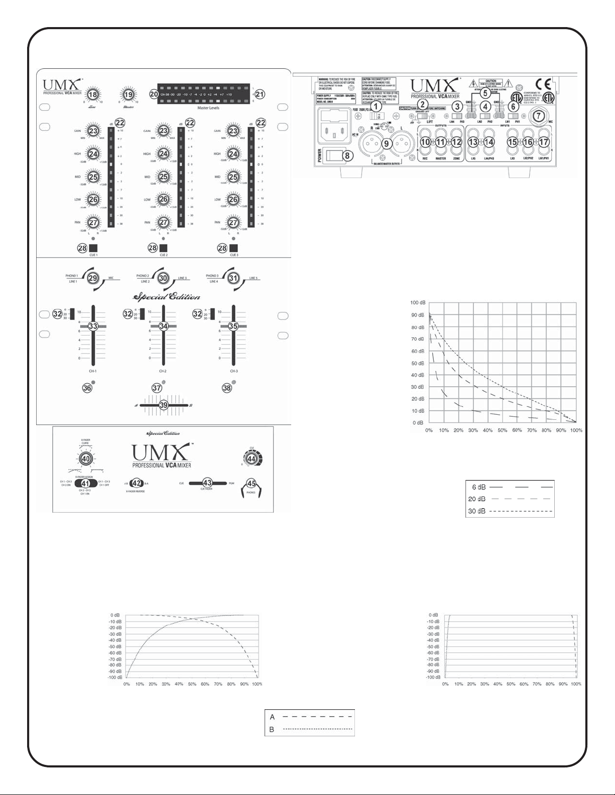
FRONT: BACK:
Channel Slide Curve
Kanalfaderkurve
Curva de los mandos deslizantes
de canal
Courbe des curseurs de canal
Curva cursori canale
A/B Amplitude (dB)
A/B-Signalstärke (dB)
Amplitud A/B (dB)
Amplitude A/B (dB)
Estensione A/B (dB)
Gradual Taper
Weicher Übergang
Disminución progresiva
Diminution progressive
Riduzione progressiva
CROSSFADER
Adjustment
CROSSFADER-Regelweg
Ajuste del CROSSFADER
Réglage du
CROSSFADER
Regolazione
CROSSFADER
Attenuation (dB)
Dämpfung (dB)
Atenuacion (dB)
Atténuation (dB)
Attenuazione (dB)
A/B Amplitude (dB)
A/B-Signalstärke (dB)
Amplitud A/B (dB)
Amplitude A/B (dB)
Estensione A/B (dB)
Travel (%)
Faderweg (%)
Recorrido (%)
Parcours (%)
Corso (%)
Radical Taper
Harter Übergang
Disminución radical
Diminution radicale
Riduzione radicale
Travel (%)
Faderweg (%)
Recorrido (%)
Parcours (%)
Corso (%)
(3)(3)
(3)
(3)(3)
Travel (%)
Faderweg (%)
Recorrido (%)
Parcours (%)
Corso (%)
Page 4
INTRODUCTION:
Congratulations on purchasing the UMX DIVISION UMX-SE VCA mixer.
This state of the art mixer is backed by a three year warranty, excluding
CROSSFADER and channel slides. Prior to use, we suggest that you
carefully read all the instructions. With VCA technology, audio is
processed in a voltage-control LED amplifier (VCA) removing it from the
CROSSFADER and channel slides giving them extended life and
reducing travel noise. The CROSSFADER and channel slides regulate
the DC voltage that controls the VCA circuit. Additional advantages of
VCA technology include the ability to provide precise curve adjustments
for the CROSSFADER and channel slides without sacrificing audio
quality. For additional information, refer to the diagrams on PAGE 3 for
CROSSFADER adjustment and channel slide curve.
FEATURES:
• 3 Stereo Channels
• State of the Art Cue Section
• 3 Phono/Line Convertible, 2 Line, and 1 Mic Input
• Cut Feature for Low, Mid and High on each channel
• Gain, High, Mid and Low tone controls on each channel
• Balanced and Unbalanced Master Outputs
• Zone and Record Outputs
• Master Output Peak Hold LED Meters
• Prefader Input Level Peak Hold LED Meters for each channel
• Adjustable Input Assign Switches
• Channel Slide Curve Control
• Assignable CROSSFADER with Curve Control
• CROSSFADER Reverse (Hamster) Switch
CAUTIONS:
1. All operating instructions should be read before using this equipment.
2. To reduce the risk of electrical shock, do not open the unit. There are NO
USER REPLACEABLE PARTS INSIDE. Please refer servicing to a
qualified service technician.
IN THE U.S.A., IF YOU HAVE ANY PROBLEMS WITH THIS UNIT, CALL 1-732-738-9003
FOR CUSTOMER SERVICE. DO NOT RETURN EQUIPMENT TO YOUR DEALER.
3. Do not expose this unit to direct sunlight or to a heat source such as a
radiator or stove.
4. This unit should be cleaned only with a damp cloth. Avoid solvents or
other cleaning detergents.
5. When moving this equipment, it should be placed in its original carton and
packaging. This will reduce the risk of damage during transit.
6. DO NOT EXPOSE THIS UNIT TO RAIN OR MOISTURE.
7. DO NOT USE ANY SPRAY CLEANER OR LUBRICANT ON ANY
CONTROLS OR SWITCHES.
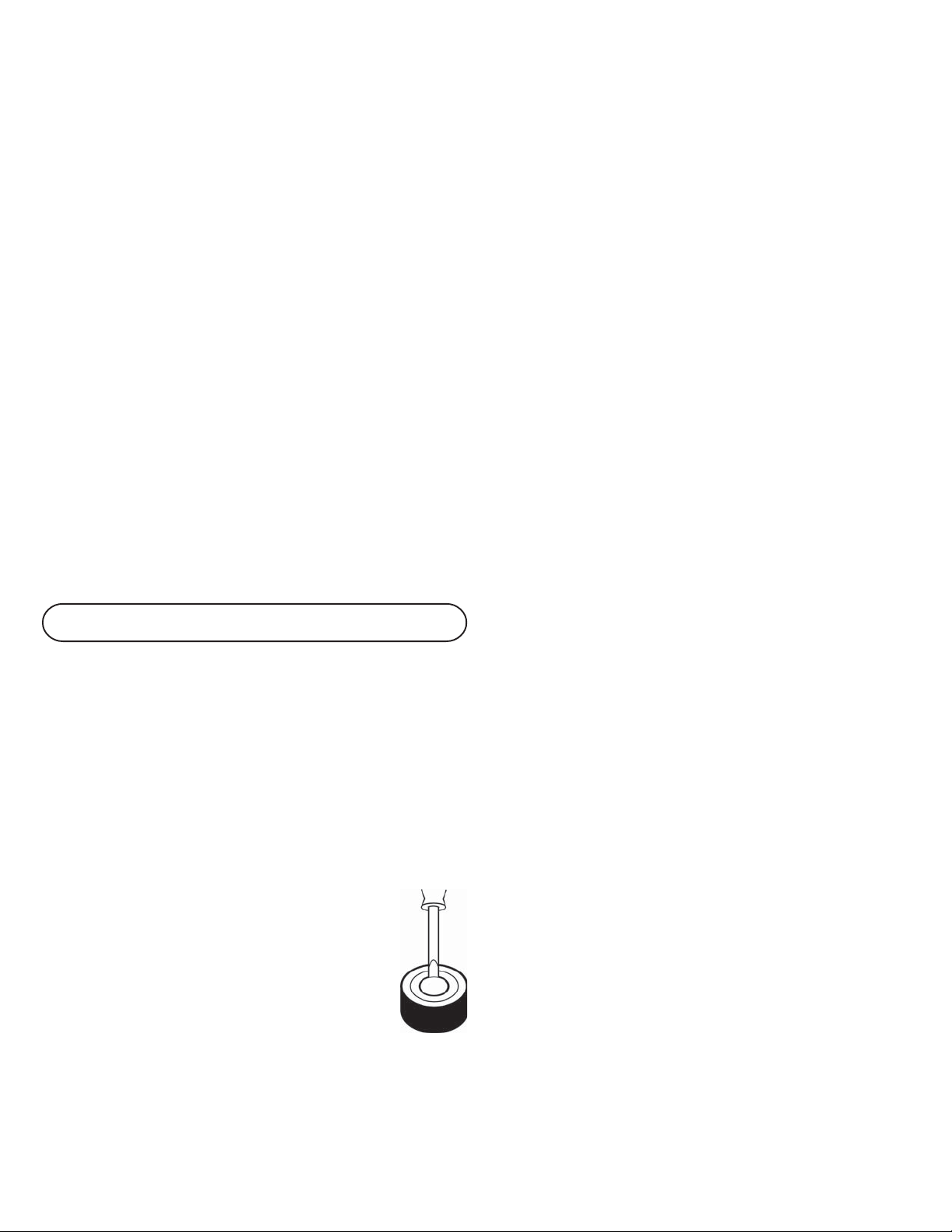
HEIGHT ADJUSTMENT:
When using a UMX mixer with professional turntables, such
as the UMX DIVISIONPT Series, you can make the mixer
level with the turntable by removing the mixer’s feet.
1. Place a small screw driver under the foot’s center anchor.
2. Gently pry the center anchor up and the foot will come OFF.
To replace the foot:
1. Place the foot on the mixer without the center anchor.
2. Replace the center anchor and push down on it to anchor the foot to the
mixer.
CONNECTIONS:
1. Before plugging in the power cord, make sure that the VOLTAGE
SELECTOR (1) switch is set to the correct voltage.
2. Make sure that the POWER (8) switch is in the OFF position. The
POWER LED (20) will be OFF.
3. The UMX-SE is supplied with 4 sets of output jacks. The BALANCED
MASTER OUTPUT (9) jacks are used to connect to your main amplifier
using standard XLR cables. We recommend using the balanced amp
outputs if the cables to your amp are 10 feet or more. BALANCED
MASTER OUTPUTS have three separate conductors, two of which are
signal (positive and negative) and one shield (ground). Pin 1 is ground
(shield). Pin 2 is signal hot (positive). Pin 3 is signal cold (negative). The
MASTER OUTPUT (11) jacks are unbalanced and used to connect to
your main amplifier. The REC OUTPUT (10) jacks can be used to
connect the mixer to the record input of your recorder enabling you to
record your mix. The ZONE OUTPUT (12) jacks allow you to hook up an
additional amplifier.
4. The MIC (7) input (found on the rear panel) accepts a 1/4" connector
and balanced and unbalanced microphones.
5. On the rear panel are 3 stereo PHONO/LINE (14, 16, 17) inputs and 2
stereo LINE (13, 15) inputs. The PHONO/LINE SWITCH (3) enables you
to set the (14) input to Phono or Line. The PHONO/LINE SWITCH (4)
enables you to set the (16) input to Phono or Line. The PHONO/LINE
SWITCH (6) enables you to set the (17) input to Phono or Line. The
phono inputs will accept only turntables with a magnetic cartridge.
GROUND SCREWS (5) for you to ground your turntables are located on
the rear panel. The stereo line inputs will accept any line level input such
as a CD player, a cassette player, etc.
6. Headphones can be plugged into the front panel mounted PHONES (45) jack.
USING THE GROUND LIFT SWITCH:
Depending on your system configuration, sometimes applying the ground
will create a quieter signal path. Sometimes lifting the ground can
eliminate ground loops and hum to create a quieter signal path.
1. With the mixer on, listen to the system in idle mode (no signal present)
with the ground applied (the GROUND LIFT SWITCH (2) in the left
position).
2. Then turn the power OFF before moving the GROUND LIFT
SWITCH (2). Lift the ground by moving the GROUND LIFT SWITCH to
the right, turn the power back on and listen to determine which position
will provide a signal devoid of background noise and hum. Keep the
GROUND LIFT SWITCH in the ground position if the noise level remains
the same in either position.
CAUTION: DO NOT TERMINATE THE AC GROUND ON THE POWER MIXER IN ANY WAY.
TERMINATION OF THE AC GROUND CAN BE HAZARDOUS.
OPERATION:
1. POWER ON: Once you have made all the equipment connections to your
mixer, press the POWER (8) switch. The power will turn on and the
POWER LED (20) will light.
2. CHANNEL 1: The GAIN (23), HIGH (24), MID (25), LOW (26), and PAN
(27) controls allow you to fully adjust the selected source. Switch # (29)
allows you to select the PHONO 1/LINE 1 (17) or the MIC (7) input. The
CHANNEL SLIDE (33) controls the input level of this channel.
3. CHANNEL 2: The GAIN (23), HIGH (24), MID (25), LOW (26), and PAN
(27) controls allow you to fully adjust the selected source. Switch # (30)
allows you to select the PHONO 2/LINE 2 (16) or the LINE 3 (15) input.
The CHANNEL SLIDE (34) controls the input level of this channel.
4. CHANNEL 3: The GAIN (23), HIGH (24), MID (25), LOW (26), and PAN
(27) controls allow you to fully adjust the selected source. Switch # (31)
allows you to select the PHONO 3/LINE 4 (14) or the LINE 5 (13) input.
The CHANNEL SLIDE (35) controls the input level of this channel.
5. TONAL CONTROLS: There is Low, Mid and High equalization for each
channel with an extremely wide range of adjustment.
SUGGESTION: YOU CAN USE THE CUT FEATURES ON EACH CHANNEL TO REMOVE LOW,
MID AND/OR HIGH TO CREATE SPECIAL EFFECTS.
6. INPUT ASSIGN SWITCHES: You can adjust the position of the INPUT
ASSIGN (29, 30, 31) switches to move left to right, up and down OR at
a 45 degree angle. Make these adjustments with the power OFF.
(4)(4)
(4)
(4)(4)
Page 5

1) Remove the channel slide, CROSSFADER
knobs and the 4 screws from the sides
of the lower face plate. Then
remove the lower faceplate.
2) Remove the 2 screws in the corners of
the assign switch plate. Rotate the
switch plate to the desired position,
replace the screws and tighten down.
3) To position the switch at a 45 degree angle, you need to reposition the
switch on the assign switch plate. First, remove the 2 screws in the
corners of the assign switch plate. Then, lift the switch plate up and
remove the 2 smaller screws next to the switch. Rotate the switch plate
to the right until the 45 degree holes align with the switch holes, replace
the screws and tighten down. Replace the switch plate and tighten down.
NOTE: KEEP TRACK OF WHERE YOU POSITION THE INPUT ASSIGN SWITCHES. TO AVOID
CONFUSION, MOVE THE SWITCH TO A POSITION NEAR THE CORRESPONDING PRINTING
ON THE FACEPLATE.
7. CHANNEL SLIDE CURVE SWITCHES: Use the 3 position CHANNEL
SLIDE CURVE (32) switches to adjust the kind of curve the channel
slides have. Move the selected channel slide curve switch to the 6 (top)
position to make the increase in level gradual and even. Move the
channel slide curve switch to the 20 (center) position to make the
increase in level less gradual as you move channel slide up. Move the
channel slide curve switch to the 30 (bottom) position to make the
increase in level even less gradual, especially at the top of the slide.
8. CROSSFADER SECTION: The CROSSFADER (39) allows the mixing of
one source into another. The UMX-SE features an assignable
CROSSFADER. The ASSIGN (41) switch allows you to select which
channels will play through the CROSSFADER and has 3 positions. When
the ASSIGN (41) switch is in the left postion, Channel 1 will play through
A (the left side of the CROSSFADER), channel 3 will play through B (the
right side of the CROSSFADER), and channel 2 will be on but not
assigned to the CROSSFADER. When the ASSIGN (41) switch is in the
center postion, Channel 2 will play through A, channel 3 will play
through B and channel 1 will be on but not assigned the the
CROSSFADER. When the ASSIGN (41) switch is in the right position,
Channel 2 will play through A, channel 3 will play through B and channel
1 will be OFF. The CROSSFADER ASSIGN LED (36, 37, 38) indicate
which channels are assigned to the CROSSFADER. When a channel is
assigned to the CROSSFADER, the CROSSFADER ASSIGN LED will light
BLUE. When a CROSSFADER ASSIGN LED is not lit, the channel is on
but not assigned to the CROSSFADER. When the CROSSFADER
ASSIGN LED (36) lights RED, channel 1 is OFF. The CROSSFADER
CURVE (40) control allows you to adjust the kind of curve the
CROSSFADER has. Move the CROSSFADER CURVE (40) control
to the right to make the curve steep and cutting (perfect for scratching).
Move the CROSSFADER CURVE (40) control to the left to make the
curve gradual and gentle. The CROSSFADER REVERSE SWITCH (42)
allows you to reverse the CROSSFADER so that B is control LED by the
left side of the CROSSFADER and A is control LED by the right side of
the CROSSFADER.
NOTE: WHEN THE CROSSFADER REVERSE SWITCH (42) IS ACTIVATED (MOVED TO THE
RIGHT), ONLY THE CROSSFADER REVERSES. THE CHANNEL SLIDES, GAIN, PAN AND
TONAL CONTROLS DO NOT REVERSE.
9. OUTPUT CONTROL SECTION: The level of the MASTER OUTPUT (9,
11) is controlLED by the MASTER (19) control. The ZONE (18) control
adjusts the level of the ZONE OUTPUT (12).
HINT: THE ZONE OUTPUT IS USED BY SOME DJS TO RUN MONITOR SPEAKERS IN THEIR DJ
BOOTH. YOU CAN ALSO USE IT AS A SECOND ZONE OR AMP OUTPUT.
NOTE: THE RECORD OUT (10) HAS NO LEVEL CONTROL. THE LEVEL IS SET BY THE
CHANNEL SLIDES AND THE GAIN CONTROLS OF THE SELECTED CHANNEL. THE TONAL
QUALITIES ARE SET BY THE LOW, MID AND HIGH CONTROLS OF THAT SAME CHANNEL.
10.CUE SECTION: By connecting a set of headphones to the PHONES (45)
jack, you can monitor any or all of the channels. Press the CUE ASSIGN
(28) buttons for channels 1 - 3 to select the channel or channels to be
monitored and their respective LED indicators will glow. Use the CUE
LEVEL (44) control to adjust the cue volume without effecting the
overall mix. By moving the CUE FADER (43) control to the left you will be
able to monitor the assigned cue signal. Moving the control to the right
will monitor the PGM (program) output.
11. DISPLAYS: The PEAK HOLD LED METER (21) indicates the MASTER
OUTPUT (9, 11) left and right channel levels. The individual channels each
have their own PREFADER INPUT LEVEL PEAK HOLD LED METERS
(22) which reflect the GAIN (23), HIGH (24), MID (25) and LOW (26)
rotary control adjustments. The CHANNNEL SLIDES (33, 34, 35) will not
effect the PREFADER INPUT LEVEL PEAK HOLD LED METERS (22).
SPECIFICATIONS:
INPUTS:
Mic..............................................................................1.5mV 2Kohm balanced
Phono..........................................................................................3mV 47Kohm
Line........................................................................................150 mV 27Kohm
OUTPUTS:
Master (balanced).............................................................0 dB 2 V 800 Ohm
Max.....................................................................................40 V Peak to Peak
Master/Zone (unbalanced)....................................................0 dB 1V 400ohm
Max......................................................................................20V Peak to Peak
Rec...........................................................................................225mV 5Kohm
MIC:
Mic..............................................................................1.5mV 2Kohm balanced
Controls............................................................................................Channel 1
GENERAL:
Low (Chnls 1-3).......................................................................+ 12dB/- 32 dB
Mid (Chnls 1-3).........................................................................+ 12dB/- 32 dB
High (Chnls 1-3).......................................................................+ 12dB/- 32 dB
Gain (Chnls 1-3)..............................................................................0 to -20dB
Frequency Response...................................................20Hz - 20KHz +/- 2dB
Distortion...................................................................................................0.08%
S/N Ratio................................................................................better than 80dB
Headphone Impedance..........................................................................16ohm
Power Source............................................................115/230V 60/50Hz 20W
Dimensions...........................10”w x 14.75”h x 4.25”d (254 x 375 x 108 mm)
Weight............................................................................................9 lbs (4 kg)
(5)(5)
(5)
(5)(5)
Page 6

EINLEITUNG:
Wir gratulieren Ihnen zum Kauf eines UMX DIVISION UMX-SE VCA
Mischpults. Dieses moderne Mischpult enthält eine dreijährige Garantie,
ausgenommen CROSSFADER und Kanalfader. Vor Anwendung dieses
Mischpults bitte alle Anweisungen sorgfältig durchlesen. Mit der VCA-
Technologie wird das Audiosignal in einem spannungsregulierten
Verstärker (Voltage Control LED Amplifier) bearbeitet und nicht über
Crossoder Kanalfader geführt, was zu einer erhöhten Lebensdauer und
geringeren Fadergeräuschen führt. Die Cross- und Kanalfader
regulieren eine Gleichstromspannung, die wiederum die VCA-Schaltung
steuert. Ein weiterer Vorteil der VCA-Technologie ist die Möglichkeit zur
präzisen Kurvensteuerung von Cross- und Kanalfadern ohne die
Qualität des Audiosignals zu beeinflussen. Weitere Informationen finden
Sie im Diagramm auf SEITE 3, das die CROSSFADER-Regulierung und
die Kanalfaderkurve darstellt.
FUNKTIONEN:
• 3 Stereokanäle
• Aufwendige Vorhör-Sektion
• 3 Phono-/Line (umschaltbar), 2 Line und 1 Mikrophon Eingang
• CUT-Equalizer Funktion für Bässe, Mitten- und Höhen pro Kanal
• Symmetrische und unsymmetrische Master-Ausgänge
• Zonen und Aufnahme Ausgänge
• LED-Anzeige für Master-Ausgangsspitzenwertspeicherung
• Vorpegel-Eingangsspitzenwertspeicherungs-LEDs für jeden Kanal
• Verstellbare Eingang-Zuweisungsschalter
• Kanalfaderkurven-Steuerung
• Zuortbarer CROSSFADER mit Kurvensteuerung
• CROSSFADER-Reverse (Hamster) Schalter
VORSICHTSMAßNAHMEN:
1. Vor Anwendung dieses Geräts bitte alle Anweisungen sorgfältig
durchlesen.
2. Das Gerät nicht öffnen, um das Risiko elektrischen Schocks zu
vermeiden. Es enthält KEINE VOM ANWENDER ERSETZBAREN TEILE.
Die Wartung darf nur von authorisierten Wartungstechnikern
durchgeführt werden.
3. Das Gerät keinem direktem Sonnenlicht oder einer Wärmequelle wie
Heizkörper oder Ofen aussetzen.
4. Dieses Gerät darf nur mit einem feuchten Tuch gesäubert werden.
Keine Lösungs- oder Reinigungsmittel benutzen.
5. Bei Umzügen sollte das Gerät in seinem ursprünglichen Versandkarton
und Verpackungsmaterial verpackt werden. Dadurch verhindert man,
daß das Gerät während des Transportes beschädigt wird.
6. DIESES GERÄT NICHT REGEN ODER FEUCHTIGKEIT AUSSETZEN.
7. AN DEN REGLERN ODER SCHALTERN KEIN SPRAY-
REINIGUNGSMITTEL ODER SCHMIERMITTEL BENUTZEN.
HÖHENJUSTIERUNG:
Wenn man einen UMX Mixer zusammen mit professionellen
Plattenspielern wie UMX DIVISION PT Serie benutzen möchte, kann man
die gleiche Gerätehöhe der Plattenspieler erreichen, indem man
die Füße des Mixers entfernt.
1. Mit einem kleinen Schraubenzieher den mittleren Stift des
Fußes heraushebeln.
2. Vorsichtig den Stift abnehmen und den Fuß herausziehen.
Um den Fuß wieder einzusetzen:
1. Den Fuß ohne den mittleren Stift in den Mixer drücken.
2. Den mittleren Stift einsetzen und fest eindrücken, um den
Fuß im Mixer zu verankern.
ANSCHLÜSSE:
1. Bevor Sie das Stromkabel anschließen, darauf achten, daß der
VOLTAGE SELECTOR (1) (Spannungswähler) auf die richtige
Spannung (230V) einstellt ist.
2. Darauf achten, daß der Netzschalter POWER (8) in OFF-Position
geschaltet ist. Die POWER LED (20) (Netzkontrolleuchte) darf nicht
leuchten.
3. Der UMX-SE verfügt über 4 Ausgangsbuchsenpaare. . Die Buchsen
BALANCED MASTER OUTPUT (9) dienen zum Anschluß an den
Hauptverstärker, wofür Standard-XLR-Kabel benutzt werden. Wir
empfehlen, die symmetrischen Master-Ausgänge zu benutzen, wenn die
Kabel zu Ihrem Verstärker 3 m oder länger sind. Symmetrische
Ausgänge haben drei (3) verschiedene Leiter, zwei für Signal (positiv
und negativ) und einen für Masse. An Pin 1 (Stift 1) gehört die Masse
(Erdung). An Pin 2 (Stift 2) gehört das aktive Signal (positiv). An Pin 3
(Stift 3) gehört das inaktive Signal (negativ). Die Buchsen MASTER
OUTPUT (11) sind unsymmetrisch und dienen zum Anschluß an einen
Hauptverstärker ohne symmetrischen Eingang. Die Buchsen REC
OUTPUT (10) können dazu dienen, das Mischpult an den
Aufnahmeeingang des Aufnahmegerätes anzuschließen, um die
Tonmischung aufnehmen zu können. Die Buchsen ZONE OUTPUT (12)
ermöglichen Anschluß an einen zusätzlichen Verstärker.
4. Der Eingang MIC (7) (an der Rückwand angebracht) nimmt
Klinkenstecker mit Durchmesser von 6,3 mm (1/4") für symmetrische und
unsymmetrische Mikrophone auf.
5. An der Rückwand sind jeweils 3 Stereoeingänge PHONO/LINE (14, 16,
17) und 2 Stereoeingänge LINE (13, 15). Der Schalter PHONO/LINE (3)
ermöglicht Ihnen, die Eingänge (14) zwischen Phono oder Line
umzuschalten. Der Schalter PHONO/LINE (4) ermöglicht Ihnen, die
Eingänge (16) zwischen Phono oder Line umzuschalten. Der Schalter
PHONO/LINE (6) ermöglicht Ihnen, die Eingänge (17) zwischen Phono
oder Line umzuschalten. Die Phono-Eingänge sind ausschließlich für
Plattenspieler mit einem magnetischem Tonabnehmer zu verwenden.
Erdungschrauben - GROUND SCREWS (5) zur Erdung des
Plattenspielers sind an der Rückwand angebracht. Die Stereo-LineEingänge sind für den Anschluß von CD-, MD- oder Kassettengeräten
vorgesehen.
6. Ein Kopfhörer kann an der an der Vorderseite montierten KopfhörerBuchse PHONES (45) eingesteckt werden.
BENUTZUNG DES MASSE
TRENNSCHALTERS:
Abhängig von Ihrer Systemkonfiguration, wenn man hin und wieder
Masse anlegt, kann man damit einen brummfreien Signalweg erreichen.
Wenn man die Masse trennt, kann man dadurch Erdungsschleifen und
Brummen eliminieren, um einen ruhigeren Signalpfad zu erhalten.
1. Wenn das Mischpult eingeschaltet ist, das System im Ruhemodus (ohne
Signal) bei angelegter Masse abhorchen (der Masse-Trennschalter
GROUND LIFT SWITCH (2) ist nach links geschaltet).
2. Achtung ! Den Netzschalter ausschalten, bevor der Mass-
Trennschalter betätigt wird! Den Trennschalter nach rechts
schieben, Netz wieder einschalten und prüfen ob die Brummgeräusche
eliminiert sind. Falls der Geräuschpegel in beiden Positionen unverändert
bleibt, unbedingt den Trennschalter wieder in Masseposition bringen.
VORSICHT: NIEMALS DIE ERDUNG (MASSE) AM MISCHPULT ABKLEMMEN. DIES KANN ZU
GEFAHREN UND STROMSCHLÄGEN FÜHREN.
BEDIENUNG:
1. NETZ EINSCHALTEN: Nachdem Sie alle Tonquellen am Mischpult
angeschlossen haben, drücken Sie auf die Taste POWER (8). Der Strom
wird eingeschaltet und die POWER LED (20) leuchtet auf.
2. KANAL 1: Die Regelelemente GAIN (23), HIGH (24), MID (25), LOW
(26), und PAN (27) (Balance) ermöglichen ein vollkommenes Regulieren
der ausgewählten Tonquelle. Schalter # (29) ermöglicht, den Eingang
von PHONO 1/LINE 1 (17) oder MIC (7) auszuwählen. CHANNEL SLIDE
(33) regelt den Ausgangspegel dieses Kanals.
(6)(6)
(6)
(6)(6)
Page 7

3. KANAL 2: Die Regelelemente GAIN (23), HIGH (24), MID (25), LOW
(26), und PAN (27) (Balance) ermöglichen ein vollkommenes Regulieren
der ausgewählten Tonquelle. Schalter # (30) ermöglicht, den Eingang
von PHONO 2/LINE 2 (16) oder LINE 3 (15) auszuwählen. CHANNEL
SLIDE (34) regelt den Ausgangspegel dieses Kanals.
4. KANAL 3: Die Regelelemente GAIN (23), HIGH (24), MID (25), LOW
(26), und PAN (27) (Balance) ermöglichen ein vollkommenes Regulieren
der ausgewählten Tonquelle. Schalter # (31) ermöglicht, den Eingang
von PHONO 3/LINE 4 (14) oder LINE 5 (13) auszuwählen. CHANNEL
SLIDE (35) regelt den Ausgangspegel dieses Kanals.
5. KLANGREGLER: Für jeden Kanal gibt es separate Bass- (Low), Mitten(Mid) und Höhen- (High) Regler mit einem äusserst breiten
Regulierbereich, die eine flexible Mischung bieten.
PROFI-TIP: SIE KÖNNEN DIE CUT FUNKTION EINES JEDEN KANALS BENUTZEN, UM LOW, MID
UND/ODER HIGH AUSZUBLENDEN UM DADURCH SPEZIALEFFEKTE ZU ERZIELEN.
6. EINGANGSZUWEISUNGSSCHALTER: Sie können die Position der
INPUT ASSIGN (29, 30, 31) Schalter ändern, wenn Sie die Schalter von
links nach rechts und von oben nach unten ODER in einem Winkel von
45 Grad bedienen möchten. Diese Einstellungen werden vorgenommen,
wenn der Netzschalter in OFF-Position steht.
1) Die Kanalfader-, die Crossfaderknöpfe
von den Fadern und die 4 Schrauben der
unteren Frontplatte entfernen. Dann die
untere Frontplatte entfernen.
2) Die 2 Schrauben an den Ecken der
Zuweisungs-Schalterplatte entfernen.
Die Schalterplatte in die gewünschte
Position drehen, die Schrauben wieder
einsetzen und festziehen.
3) Um den Schalter in einen Winkel von 45 Grad zu positionieren, den
Schalter auf der Zuweisungs-Schalterplatte umpositionieren. Dann die
Schalterplatte anheben und die 2 kleineren Schrauben neben dem
Schalter entfernen. Die Schalterplatte nach rechts drehen, bis
die Löcher im Winkel von 45 Grad mit den Schalterlöchern ausgerichtet
sind, die Schrauben wieder einsetzen und estziehen. Die Schalterplatte
wieder aufsetzen und festschrauben.
HINWEIS: DARAUF ACHTEN, WO SIE DIE EINGANGSZUWEISUNGSSCHALTER POSITIONIEREN.
UM VERWIRRUNG ZU VERMEIDEN, MÜSSEN DIE SCHALTER IN EINE POSITION IN DER
NÄHE DES ENTSPRECHENDEN AUFDRUCKS DER FRONTPLATTE GESCHOBEN WERDEN.
7. KANALFADERKURVEN-SCHALTER: Die 3 CHANNEL SLIDE CURVE
(32) Positionschalter benutzen, um die Kurvenart der Kanalfader
einzustellen. Den gewählten Kanalfaderkurven-Schalter in Position 6
(oben) schieben, um einen allmählichen und sanften Signalpegelanstieg
zu ermöglichen. Den Kanalfaderkurven-Schalter in Position 20 (Mitte)
schieben, um einen weniger sanften Signalpegelanstieg zu ermöglichen,
wenn der Kanal aufwärts geschoben wird. Den KanalfaderkurvenSchalter in Position 30 (unten) schieben, um einen schnell zunehmenden
Signalpegelanstieg zu ermöglichen, besonders am oberen Ende des
Faders.
8. CROSSFADER: Der Überblender CROSSFADER (39) ermöglicht das
Mischen von Tonquellen. Der UMX-SE bietet einen zuweisbaren
CROSSFADER. Die ASSIGN (41) Schalter ermöglichen Ihnen denjenigen
Kanal auszuwählen, der durch den CROSSFADER eingeblendet wird
und 3 Positionen hat. Steht der ASSIGN (41) Schalter in der linken
Position, wird Kanal 1 durch A, (die linke Seite des Crossfaders),
Kanal 3
durch B (die rechte Seite des Crossfaders) eingeblendet, Kanal 2 ist
zwar aktiv, aber nicht dem CROSSFADER zugewiesen . Steht der
ASSIGN (41) Schalter in Mittenposition, wird Kanal 2 durch A, Kanal 3
durch B eingeblendet, Kanal 1 ist aktiv, aber nicht dem CROSSFADER
zugewiesen. Steht der ASSIGN (41) Schalter in Rechtsposition, wird
Kanal 2 durch A, Kanal 3 durch B eingeblendet, und Kanal 1
ausgeschaltet, und auch nicht dem CROSSFADER zugewiesen . Die
CROSSFADER ASSIGN LED (36, 37, 38) zeigen an, welche Kanäle dem
CROSSFADER zugeordnet sind. Wenn ein Kanal dem CROSSFADER
zugewiesen ist, wird die CROSSFADER ASSIGN LED BLAU
aufleuchten. Wenn eine CROSSFADER ASSIGN LED nicht aufleuchtet,
ist der Kanal aktiv, aber nicht dem CROSSFADER zugewiesen. Wenn die
CROSSFADER ASSIGN LED (36) rot erleuchtet, ist der Kanal
ausgeschaltet. Die CROSSFADER CURVE (40) Steuerung
ermöglicht Ihnen, die Kurven des Crossfaders einzustellen. Die
CROSSFADER CURVE (40) Steuerung nach rechts verschieben, um
eine steile und schneidende Kurve zu erzielen (ideal für Scratching). Die
CROSSFADER CURVE (40) Steuerung nach links verschieben, um eine
allmählich ansteigende und sanfte Kurve zu erzielen. Der CROSSFADER
REVERSE SWITCH (42) ermöglicht den seitenverkehrten Betrieb des
Crossfaders, so daß B durch die linke Seite und A durch die rechte
Seite des Crossfaders geregelt wird.
HINWEIS: IST DER CROSSFADER-REVERSE-SCHALTER (42) AKTIVIERT (NACH RECHTS
GESCHOBEN), LÄUFT NUR DER CROSSFADER IN GEGENRICHTUNG. DIE KANALFADER,
VORPEGEL-, BALANCE- UND TONREGLER WERDEN HIERVON NICHT BEEINFLUSST.
9. AUSGANGSREGELUNG: Der Pegel des MASTER OUTPUT (9, 11)
(Verstärkerausgang) wird mittels des Drehreglers MASTER (19)
gesteuert. Der Regler ZONE (18) justiert den Pegel des ZONE OUTPUT
(12). EMPFEHLUNG: Die ZONE OUTPUT wird von einigen DJs benutzt,
um die Lautsprecher in der DJ-Kabine separat zu überwachen.
benfalls kann es als zweiter Verstärker-Ausgang benutzt werden.
HINWEIS: RECORD OUT (10) VERFÜGT ÜBER KEINEN EIGENEN PEGELREGLER. DER PEGEL
WIRD DURCH DIE KANALFADER UND DIE VORPEGELREGLER DES AUSGEWÄHLTEN
KANALS BEEINFLUSST. DIE TONQUALITÄT WIRD DURCH DIE TIEFEN-, HÖHEN, UND
MITTELBEREICHSREGLER DIESES KANALS EINGESTELLT.
10.VORHÖR SEKTION: Den Kopfhörer an der Buchse KOPFHÖRER PHONES (45) anschließen, um einen oder alle Kanäle abzuhören.
Drücken Sie die Tasten CUE ASSIGN (28) für Kanäle 1-3, um den/die zu
kontrollierende/n Kanal/Kanäle auswählen, die jeweilige LED-Anzeige
leuchtet auf. Betätigen Sie den Regler CUEING LEVEL (44), um die
Mithörlautstärke einzustellen, ohne dabei die allgemeine Mischung zu
beeinträchtigen. Indem Sie den Regler CUE FADER (43) nach links
schieben, können Sie das zugewiesene Mithörsignal kontrollieren. Nach
rechts schieben erhöht den Abhörpegel des PGM- (Programm-) bzw.
Mastersignales.
11. ANZEIGEN: Die Spitzenwertanzeige PEAK HOLD LED METER (21) zeigt
die linken und rechten Kanalpegel des MASTER OUTPUT (9, 11) an. Die
individuellen Kanäle haben jeweils ihre eigenen VorpegelEingangsspitzenwertspeicherungs-LEDs (22), die durch die
Drehknopfeinstellungen GAIN (23), HIGH (24), MID (25) und LOW (26)
beeinflusst werden. Die Kanalschieberegler (33, 34, 35) haben keinen
Einfluss auf die Vorpegel-LEDs (22).
TECHNISCHE DATEN:
EINGÄNGE:
Mikrophon..........................................................1,5 mV, 2 kOhm symmetrisch
Phono (Plattenspieler)..............................................................3 mV, 47 kOhm
Line (CD, MD, Kassette).......................................................150 mV, 27 kOhm
AUSGÄNGE:
Master (symmetrisch)........................................................0 dB 2 V 800 Ohm
max....................................................................................40 V Spitze-Spitze
Master/Zone (unsymmetrisch)..........................................0 dB 1 V 400 Ohm
max....................................................................................20 V Spitze-Spitze
Record (Aufnahme)................................................................225 mV 5 kOhm
MIKROFON:
Mikrophon......................................................1,5 mV, 2 kOhm unsymmetrisch
Regelmöglichkeit über...........................................................................Kanal 1
ALLGEMEINES:
Tiefenregler (Kanäle 1 - 3).......................................................+ 12dB/- 32 dB
Mittenregler (Kanäle 1 - 3)......................................................+ 12dB/- 32 dB
Höhenregler (Kanäle 1 - 3).....................................................+ 12dB/- 32 dB
Vorpegelregler (Kanäle 1 - 3)......................................................0 bis -20 dB
Frequenzgang............................................................20 Hz - 20 kHz +/- 2 dB
Klirrfaktor................................................................................................0,08%
Störabstand..........................................................................besser als 80 dB
Kopfhörerimpedanz.............................................................................16 Ohm
Netzspannung........................................................115/230 V, 60/50 Hz, 20W
Abmessungen.................................................................254 x 375 x 108 mm
Gewicht.....................................................................................................4 kg
(7)(7)
(7)
(7)(7)
Page 8

INTRODUCCIÓN:
Felicitaciones por su compra del mezclador VCA, modelo UMX-SE, de
UMX DIVISION. Este mezclador de la más avanzada tecnología está
respaldado por una garantía de tres años, salvo el CROSSFADER y los
mandos deslizantes de canal. Antes de usarlo, le recomendamos leer
cuidadosamente todas las instrucciones. Con la tecnologia VCA, el
audio se procesa en un amplificador de tensión controlada (VCA) que lo
saca del CROSSFADER y de los mandos deslizantes de canal lo que
les da larga vida y menos ruido de recorrido. El CROSSFADER y los
mandos deslizantes de canal regulan la tensión de corriente continua
que controla el circuito VCA. Otras ventajas ofrecidas por la tecnologia
VCA son la capacidad de proveer ajustes de curva precisos para el
CROSSFADER y los mandos deslizantes de canal sin sacrificar la
calidad auditiva. Para más informaciones, véase los diagramas en la
página 3 para el ajuste del CROSSFADER y para la curva de los mandos
deslizantes de canal.
CARACTERÍSTICAS:
• 3 canales estereo
• Sección Cue de última generación
• 3 entradas fono/línea convertible, 2 entradas de línea y 1
entrada para micrófono
• Característica CUT (Supresión) para Bajas, Medianas y Altas
Frecuencias para los canales 1 - 3
• Mandos de Ganancia, Bajas, Medianas y Altas para los canales 1 - 3
• Salidas maestras balanceadas y no balanceadas
• Salidas para zona y grabación
• Medidores LED de Master Output Peak Hold
• Medidores LED de Prefader Input Level Peak Hold para cada canal
• Interruptores de asignación de entrada ajustables
• Control de la curva del cursor deslizante del canal
• CROSSFADER asignable con control de la curva
• Inversor (Hamster) del CROSSFADER
PRECAUCIONES:
1. Deberán leerse todas las instrucciones de operación antes de usar el
equipo.
2. Para reducir el riesgo de shock eléctrico, no abra esta unidad. No
contiene PIEZAS REEMPLAZABLES POR EL USUARIO. Por favor,
refiera el servicio a un técnico de servicio calificado.
3. No exponga la unidad a la luz solar directa ni a una fuente de calor, por
ejemplo, un radiador o estufa.
4. Esta unidad sólo deberá limpiarse con un paño húmedo. Evite el uso de
disolventes u otros detergentes de limpieza.
5. Para mover este equipo, colóquelo en la caja y embalaje original, a fin de
reducir el riesgo de daños durante el transporte.
CONEXIONES:
1. Antes de conectar el cable de potencia, cerciórese de que el VOLTAGE
SELECTOR (1) (SELECTOR DE VOLTAJE) esté posicionado en la
tensión correcta.
2. Cerciórese de que el interruptor de POWER (8) (ENERGÍA) esté en la posición
OFF (apagada). El POWER LED (20) (LED de ENERGÍA) estará apagado.
3. El aparato UMX-SE está dotado de 4 series de jacks de salida para
amplificador. Los jacks BALANCED MASTER OUTPUT (9) (salida de
amplificador balanceada) se usan para la conexión al amplificador
principal con la ayuda de cables XLR estándares. Recomendamos el
uso de salidas de amplificador balanceadas si los cables que se
conectan al amplificador miden por lo menos 3 metros. A las salidas
balanceadas corresponden tres (3) conductores distintos: dos para la
función señal (positiva y negativa) y uno para la protección (tierra). Pin
1 (espiga 1) corresponde a la tierra (protección). Pin 2 (espiga 2)
corresponde a la función de señal activa (positiva). Pin 3 (espiga 3)
corresponde a la función de señal inactiva (negativa). Los jacks
MASTER OUTPUT (11) (amplificador de salida) no son balanceados y
se usan para la conexión al amplificador principal. Los jacks REC
OUTPUT (10) se usan para conectar el mezclador a la entrada de su
registrador lo que le permite registrar su propia mezcla de música. Los
jacks ZONE OUTPUT (12) (cabina de zona) le permiten conectar otro
amplificador.
4. La entrada MIC (7) (que se encuentra en el panel trasero) acepta
conector de 1/4 de pulgada y micrófonos balanceados y no balanceados.
5. En el panel trasero hay 3 entradas estereo PHONO/LINE (14, 16, 17) y 2
entradas estereo LINE (13, 15). El conmutador PHONO/LINE (3) le
permite arreglar la entrada (14) a Phono o Line (fonográfico o línea). El
conmutador PHONO/LINE (4) le permite arreglar la entrada (16) a Phono
o Line (fonográfico o línea). El conmutador PHONO/LINE (6) le permite
arreglar la entrada (17) a Phono o Line (fonográfico o línea). Las
entradas fonográficas solamente aceptarán giradiscos con cápsula
magnética. Tornillos de tierra - GROUND SCREWS (5) para poner los
giradiscos a tierra se encuentran en el panel trasero. Las entradas de
línea estereo aceptarán cualquier entrada de nivel de línea tal como
reproductor de discos compactos o platina de cassette, etc.
6. Los auriculares se enchufan en el jack de PHONES (45) (auriculares)
montado en el panel delantero.
USO DEL INTERRUPTOR DE SEPARACIÓN
DE TIERRA (GROUND LIFT):
Según la configuración de su sistema, a veces el hecho de aplicar la
tierra/masa resultará en una vía de señal con menos ruido. A veces, el
hecho de separar la tierra puede eliminar bucles de tierra y zumbido
para crear una vía de señal con menos ruido.
6. NO DEJE ESTA UNIDAD EXPUESTA A LLUVIA O HUMEDAD.
7. NO USE LIMPIADORES DE SPRAY O LUBRICANTES EN
CUALESQUIER CONTROLES O INTERRUPTORES.
AJUSTE DE ALTURA:
Cuando se usa el mezclador UMX con giradiscos profesionales tales
como los de la serie PT de UMX DIVISION, es posible poner el
mezclador y el giradiscos en el mismo nivel sacando las patas del
mezclador.
1. Coloque un pequeño destornillador debajo del anclaje
central de la pata.
2. Levante cuidadosamente el anclaje central y la pata se
separará. Para reponer la pata:
1. Coloque la pata en el mezclador sin el anclaje central.
2. Reponga el anclaje central y empuje hacia abajo para
anclar la pata al mezclador.
1. Con el mezclador prendido, escuche el sistema en modo de reposo (sin
presencia de señal) con tierra aplicada (GROUND LIFT SWITCH (2) en
la posición izquierda).
2. Apague el aparato antes de desplazar el GROUND LIFT SWITCH
(2). Separe la tierra del marco moviendo el GROUND LIFT SWITCH a la
derecha, prenda el aparato de nuevo y escuche para determinar cual de
las posiciones le dará señal sin ruido de fondo y sin zumbido. Mantenga
el GROUND LIFT SWITCH en la posición de puesta a tierra si el nivel del
ruido permanece igual.
CUIDADO: NO TERMINE DE NINGUNA MANERA LA TIERRA C.A. EN EL MEZCLADOR. EL
HECHO DE TERMINAR LA TIERRA C.A. PUEDE SER PELIGROSO.
FUNCIONAMIENTO:
1. ENCENDIDO: Una vez que haya efectuado todas las conexiones de los
equipos a su mezclador, oprima el POWER (8) (INTERRUPTOR DE
ENERGÍA). Se encenderá la unidad así como el POWER LED (20).
2. CANAL 1: Los mandos de GAIN (23) (ganancia), HIGH (24) (alto), MID (25)
(mediano), LOW (26) (bajo) y PAN (27) (balancear) le permiten arreglar
plenamente la fuente seleccionada. El interruptor # (29) le permite seleccionar
la entrada PHONO 1/LINE 1 (17) o MIC (7). El CHANNEL SLIDE (33) (cursor
deslizante de canal) controla el volumen de salida de este canal.
(8)(8)
(8)
(8)(8)
Page 9

3. CANAL 2: Los mandos de GAIN (23) (ganancia), HIGH (24) (alto), MID
(25) (mediano), LOW (26) (bajo) y PAN (27) (balancear) le permiten
arreglar plenamente la fuente seleccionada. El interruptor # (30) le
permite seleccionar la entrada PHONO 2/LINE 2 (16) o LINE 3 (15). El
CHANNEL SLIDE (34) (cursor deslizante de canal) controla el volumen
de salida de este canal.
4. CANAL 3: Los mandos de GAIN (23) (ganancia), HIGH (24) (alto), MID
(25) (mediano), LOW (26) (bajo) y PAN (27) (balancear) le permiten
arreglar plenamente la fuente seleccionada. El interruptor # (31) le
permite seleccionar la entrada PHONO 3/LINE 4 (14) o LINE 5 (13). El
CHANNEL SLIDE (35) (cursor deslizante de canal) controla el volumen
de salida de este canal.
5. MANDOS DE LA TONALIDAD: Existe igualación de los tonos bajos,
medianos y altos para cada canal con muy amplio alcance de ajuste lo
que le permite obtener mejor mezcla. SUGERÉNCIA: Puede usar las
funciones CUT en cada canal para suprimir los tonos bajos, medianos y/
o altos para crear efectos especiales.
6. INTERRUPTORES INPUT ASSIGN (ASIGNACIÓN DE ENTRADA): Se
puede arreglar la posición de los interruptores INPUT ASSIGN (29, 30,
31) para mover de derecha a izquierda, de arriba abajo O en ángulo de
45 grados. Haga los ajustes con el aparato desconectado.
1) Quite los botones del CROSSFADER,
cursor deslizante y los 4 tornillos
de los lados de la placa frontal
inferior. Saque después esta placa
frontal.
2) Quite los 2 tornillos en los rincones
de la placa del interruptor de
asignación. Gire esta placa hacia la
posición deseada, reponga los
tornillos y apriételos.
3) Para posicionar el interruptor en un ángulo de 45 grados, hace falta
reposicionar el interruptor en la placa del interruptor de asignación.
Primero, saque los 2 tornillos en los rincones de la placa. Después,
levante la placa del interruptor y saque los 2 tornillos más pequeños al
lado del interruptor. Gire la placa hacia la derecha hasta que los orificios
de 45 grados se alineen con los orificios del interruptor, reponga los
tornillos y apriételos. Reponga la placa del interruptor y apriételos.
NOTA: OBSERVE DONDE SE POSICIONAN LOS INTERRUPTORES DE ASIGNACIÓN DE
ENTRADA. PARA EVITAR TODA CONFUSIÓN, MUEVA EL INTERRUPTOR HACIA UNA
POSICIÓN CERCA DE LA LEYENDA CORRESPONDIENTE EN LA PLACA FRONTAL.
7. INTERRUPTORES DE LA CURVA DE LOS CURSORES
DESLIZANTES DEL CANAL: Use los interruptores CHANNEL SLIDE
CURVE (32) de 3 posiciones para adaptar la curva de los cursores
deslizantes del canal. Mueva el interruptor de la curva escogido
hacia la posición 6 (arriba) para aumentar el nivel de manera
progresiva y uniforme. Mueva el interruptor de la curva hacia la posición
20 (central) para aumentar el nivel de forma menos progresiva al mover
el cursor del canal hacia arriba. Mueva el interruptor de la curva hacia la
posición 30 (fondo) para aumentar el nivel de forma aun menos
progresiva, especialmente en la punta superior del cursor corredizo.
8. SECCIÓN DEL ATENUADOR DE TRANSFERENCIA: El CROSSFADER
(39) (ATENUADOR DE TRANSFERENCIA) le permite mezclar una fuente
con otra. El aparato UMX-SE incluye un CROSSFADER asignable. El
interruptor ASSIGN (41) le permite seleccionar los canales que
transmitirán la música por el CROSSFADER y tiene 3 posiciones. Cuando
el interruptor ASSIGN (41) ocupa la posición izquierda, el canal 1
transmitirá a través de A (lado izquierdo del CROSSFADER), el canal 3
transmitirá a través de B (lado derecho del CROSSFADER), y el canal 2
estará activado sin estar asignado al CROSSFADER. Cuando el
interruptor ASSIGN (41) ocupa la posición central, el canal 2 transmitirá
a través de A, el canal 3 a través de B y el canal 1 estará activado sin
ser asignado al CROSSFADER. Cuando el interruptor ASSIGN (41)
ocupa la posición derecha, el canal 2 transmitirá a través de A, el canal
3 a través de B y el canal 1 estará desactivado. Los CROSSFADER
ASSIGN LED (36, 37, 38) indican cuales canales están asignados al
CROSSFADER. Cuando un canal está asignado al CROSSFADER, el
CROSSFADER ASSIGN LED se prenderá en AZUL. Cuando el
CROSSFADER ASSIGN LED no está prendido, el canal está activado sin
estar asignado al CROSSFADER. Cuando el CROSSFADER ASSIGN LED
(36) está prendido en ROJO, el canal 1 está desactivado. El pulsador
CROSSFADER CURVE (40) le permite ajustar la curva del
CROSSFADER. Mueva el pulsador CROSSFADER CURVE (40) a la
derecha para producir una curva fuerte y cortante (perfecto para
realizar el “scratching”). Mueva el pulsador CROSSFADER CURVE (40)
a la izquierda para producir una curva progresiva y moderada. El
CROSSFADER REVERSE SWITCH (42) le permite invertir el
CROSSFADER; así, B será mandado por el lado izquierdo del
74CROSSFADER y A será mandado por el lado derecho del
CROSSFADER.
NOTA: CUANDO SE ACTIVA EL CROSSFADER REVERSE SWITCH (42) (POSICIONADO A LA
DERECHA), SOLAMENTE SE PRODUCE LA INVERSIÓN DEL CROSSFADER. NO SE
PRODUCE EN LOS CURSORES DESLIZANTES DE CANALES, EN EL GAIN , EN EL PAN Y
EN LOS MANDOS DE TONALIDAD.
9. SECCIÓN DE CONTROL DE LA SALIDA: El nivel de la salida del
amplificador MASTER OUTPUT (9, 11) se controla con el control
MASTER (19). El mando ZONE (18) (zona) ajusta el volumen de ZONE
OUTPUT (12) (salida de zona). SUGERENCIA: Ciertos DJs se sirven de
la SALIDA de la cabina para sus altovoces de monitoreo en la cabina DJ.
También se puede utilizar como segunda salida de ZONA o de
AMPLIFICADOR.
NOTA: EL RECORD OUT (10) NO TIENE CONTROL DE VOLUMEN. EL VOLUMEN SE ARREGLA
POR LOS CURSORES DESLIZANTES DE LOS CANALES Y POR LOS MANDOS DE
GANANCIA DEL CANAL SELECCIONADO. LAS CALIDADES TONALES SON ARREGLADAS
POR LOS MANDOS DE BAJOS, MEDIANOS Y ALTOS DEL MISMO CANAL.
10.SECCIÓN CUE: Conectando los auriculares al jack de PHONES (45),
podrá monitorizar cualquier canal o todos los canales. Oprima los
botones CUE ASSIGN (28) para los canales 1- 3 para seleccionar el
canal o los canales a monitorizar y sus indicadores LED respectivos se
prenderán. Use el control CUE LEVEL (44) para ajustar el volumen cue
sin afectar la mezcla global. Moviendo el control CUE FADER (43) hacia
la izquierda, Ud podrá monitorizar la señal cue asignada. Moviéndolo a la
derecha, podrá monitorizar la salida del programa (PGM).
11. DISPLAYS: El PEAK HOLD LED METER (21) indica los niveles de los
canales izquiero y derecho de la MASTER OUTPUT (9, 11) (SALIDA
MAESTRA). Los canales individuales tienen cada uno sus propios
PREFADER INPUT LEVEL PEAK HOLD LED METERS (22) los cuales
reflejan los ajustes de control rotativo GAIN (23), HIGH (24), MID (25) y
LOW (26). Los CHANNEL SLIDES (33, 34, 35) (CURSORES
DESLIZANTES DE LOS CANALES) no afectarán los PREFADER INPUT
LEVEL PEAK HOLD LED METERS (22).
ESPECIFICACIONES TÉCNICAS:
ENTRADAS:
Micrófono...............................................................1,5 mV 2 Kohmios balanceados
Fono.........................................................................................3 mV 47 Kohmios
Línea.....................................................................................150 mV 27 Kohmios
Auxiliar...................................................................................150 mV 27 Kohmios
SALIDAS:
Master (balanceada).................................0 dB 2 V 800 ohmios; Máx 40 V pico-pico
Master/Zone (Zona)....................................0 dB 1 V 400 ohmios; Máx 20 V pico-pico
Grabación.................................................................................225 mV 5 Kohmios
MICRÓFONO:
Micrófono...............................................................1,5 mV 2 Kohmios balanceados
Controles..................................................................................................canal 1
GENERALES:
Bajos (canales 1 - 3)........................................................................+ 12dB/- 32 dB
Medianos (canales 1 - 3)..................................................................+ 12dB/- 32 dB
Altos (canales 1 - 3)........................................................................+ 12dB/- 32 dB
Ganancia (canales 1 - 3)....................................................................de 0 a -20 dB
Respuesta de frecuencia......................................................20 Hz - 20 kHz +/- 2dB
Distorsión...................................................................................................................0,08%
Relación señal/ruido......................................................................superior a 80 dB
Impedancia del auricular.........................................................................16 ohmios
Fuente de Alimentación......................................................115/230 V 60/50 Hz 20W
Dimensiones..........................................................................254 x 375 x 108 mm
Peso............................................................................................................4 kg
(9)(9)
(9)
(9)(9)
Page 10

INTRODUCTION:
Nos félicitations à l’occasion de votre achat du mélangeur VCA, modèle
UMX-SE, de UMX DIVISION. Ce mélangeur très moderne est
accompagné d’une garantie de trois ans, à l’exception du CROSSFADER
et fader de chaque canal. Avant de vous en servir, lisez attentivement
toutes les instructions ci-après. A l’aide de la technologie VCA, l’audio
est traité dans un amplificateur à tension contrôlée (VCA) qui le sépare
du CROSSFADER et des curseurs de canal ce qui assure une longue vie
fonctionnelle et moins de bruit de course. Le.s CROSSFADER et les
curseurs de canal régularisent la tension à courant continu qui contrôle
le circuit VCA. Parmi d’autres avantages assurés par la technologie
VCA, l’on distingue la capacité de fournir des réglages précis de la
courbe pour le CROSSFADER et les curseurs de canal sans sacrifier la
qualité audio. Pour des informations supplémentaires, voir les schémas à
la page 3 pour le réglage du CROSSFADER et la courbe des curseurs de canal.
CARACTÉRISTIQUES:
• 3 Canaux Stéreo
• Section Cue très moderne
• 3 Entrées Phono/Ligne Convertible, 2 Entrées Ligne, et 1 Entrée Micro
• Caractéristique CUT (Suppression) de Fréquences
Basses, Moyennes et Hautes pour les Canaux 1 - 3
• Commandes Gain, Basses, Moyennes et Hautes pour les Canaux 1 - 3
• Sorties Principales Symétriques (XLR) et Doublées asymétriques RCA)
• Sortie Cabine et Enregistrement
• Vu-mètre à LEDs Sortie Master avec Maintien de Crête
• Vu-mètre à LEDs sur Chaque Tranche Stéréo avec Maintien de Crête
• Commutateurs d’Assignation d’Entrée Réglables
• Réglage de Course de Chaque Fader
• CROSSFADER Assignable avec Réglage de la Courbe
• Inverseur (Hamster) du CROSSFADER
MISES EN GARDE:
1. Toutes les instructions de fonctionnement doivent être lues avant de
vous servir de cet appareil.
2. Pour réduire le risque de commotion électrique, n’ouvrez pas l’appareil. Il
ne contient AUCUNE PIÈCE À REMPLACER PAR L’UTILISATEUR. La
solution de problèmes doit être confiée à un technicien qualifié.
CONNEXIONS:
1. Avant de brancher le cordon électrique, assurez-vous que le VOLTAGE
SELECTOR (1) (sélecteur de tension) se trouve sur la tension correcte.
2. Le commutateur POWER (8) (puissance) doit occuper la position OFF
(hors tension). La POWER LED (20) (DEL de puissance) sera éteinte.
3. L’appareil UMX-SE est équipé de 4 sorties séparées (amplificateurs).
Les BALANCED MASTER OUTPUT (9) (sortie symétrique) sont utilisés
pour le branchement à l’amplificateur principal à l’aide de câbles XLR
courants. Nous recommandons l’emploi de sorties d’amplificateur
équilibrées si les câbles reliant votre amplificateur mesurent au moins 3
mètres. Aux sorties équilibrées appartiennent trois (3) conducteurs
différents: deux pour le signal (positif et négatif) et un pour la protection
(terre). Pin 1 (cheville 1) correspond à la terre (protection). Pin 2
(cheville 2) correspond au signal actif (positif). Pin 3 (cheville 3)
correspond au signal inactif (négatif). Les jacks MASTER OUTPUT (11)
(sortie amplificateur) ne sont pas équilibrés et s’utilisent pour brancher
l’amplificateur principal. Les jacks REC OUTPUT (10) (sortie
enregistrement) servent à brancher le mélangeur à l’entrée
d’enregistrement de votre enregistreur ce qui vous permet
d’enregistrer votre mélange. Les jacks ZONE OUTPUT (12) (sortie zone)
vous permettent de brancher un amplificateur supplémentaire.
4. L’entrée MIC (7) (retrouvée sur le panneau arrière) accepte un connecteur de
1/4 de pouce et des microphones équilibrés et non équilibrés.
5. Sur le panneau arrière, 3 entrées stéréo PHONO/LINE (14, 16, 17) et 2
entrées stéréo LINE (13, 15). Le PHONO/LINE SWITCH (3)
(commutateur phono/ligne) vous permet de régler l’entrée (14) sur Phono
ou Ligne. Le PHONO/LINE SWITCH (4) vous permet de régler l’entrée
(16) sur Phono ou Ligne. Le PHONO/LINE SWITCH (6) vous permet de
régler l’entrée (17) sur Phono ou Ligne. Les entrées phono n’acceptent
que des platines vinyles avec cartouche magnétique (cellule de lecture).
Des visses de terre GROUND SCREWS (5) pour la mise à la terre des
platines vinyles sont situées en face arrière du mixer. Les entrées ligne
stéréo acceptent n’importe quelle source de niveau ligne telle que
lecteur CD, platine K7, platine Mini-Disc, tuner...
6. Le casque DJ doit être connecté au jack PHONES (45) situé en face avant.
3. N’exposez pas cet appareil aux rayons directs du soleil; ne l’exposez
pas non plus à une source de chaleur (p.e. radiateur, poêle).
4. Cet appareil ne doit être nettoyé qu’avec un chiffon humide. N’utilisez
pas de solvants ou d’autre produits de nettoyage.
5. Lorsque vous déplacez cet appareil, il doit être placé dans son
emballage et carton d’origine. Ceci réduira le risque d’endommagement
lors de tout transport.
6. PROTÉGEZ CET APPAREIL CONTRE LA PLUIE OU L’HUMIDITÉ.
7. N’APPLIQUEZ AUCUN PRODUIT DE NETTOYAGE OU DE
LUBRIFICATION PULVERISÉ SUR LES COMMANDES OU LES
INTERRUPTEURS ET COMMUTATEURS.
RÉGLAGE DE LA HAUTEUR:
Lorsque vous utilisez votre console de mixage UMX avec des platines
vinyles professionnelles, comme celles de la Série PT de UMX DIVISION,
vous pouvez ajustez la hauteur de votre console de mixage à la même
hauteur que celle de vos platines vinyles en démontant les pieds de
votre console de mixage.
1. Placez un petit tournevis sous la fixation centrale des pieds.
2. Soulevez, en faisant attention, la fixation central et le pied se
séparera.
Pour remettre le pied:
1. Placez le pied sous la console de mixage sans la fixation
centrale.
2. Remettez la fixation centrale et appuyez pour fixer le pied à
la console de mixage.
COMMUTATEUR DE MISE À LA TERRE:
Selon la configuration du système, parfois la mise en place d’une terre/
masse produira une voie de signalisation moins bruyante. Parfois, le
soulèvement de la terre/masse peut éliminer des circuits de terre ou le
ronronnement pour créer une voie de signalisation moins bruyante.
1. Le mélangeur étant sous tension, écoutez le système dans le mode de
repos (sans présence de signal) tout en ayant la terre/masse en place
(le GROUND LIFT SWITCH (2) occupe la position de gauche).
2. Ensuite, mettez l’appareil hors tension avant de mouvoir le
GROUND LIFT SWITCH (2). Séparez la terre/masse en déplaçant le
GROUND LIFT SWITCH à droite, mettez l’appareil de nouveau sous
tension et écoutez pour déterminer quelle position fournira un signal
sans bruit de fond et sans ronronnement. Gardez le GROUND LIFT
SWITCH dans la position de terre/masse si le niveau de bruit reste le
même dans l’une ou l’autre position.
ATTENTION: NE JAMAIS DECONNECTER LA TERRE DE L’ALIMENTATION DE LA CONSOLE DE
MIXAGE. DECONNECTEZ LA TERRE PEUT ETRE DANGEREUX.
FONCTIONNEMENT:
1. POWER ON (MISE SOUS TENSION): Dès que tous les branchements
sont effectués à votre mélangeur, appuyez sur le POWER (8) (touche
de mise sous tension). L’appareil se mettra sous tension et la POWER
LED (20) s’allumera.
2. CANAL 1: Les commandes GAIN (23), HIGH (24) (aiguë), MID (25)
(médium), LOW (26) (basse) et PAN (27) (balance) vous permettent de
régler entièrement la source choisie. Le commutateur # (29) vous permet
de choisir l’entrée PHONO 1/LINE 1 (17) ou MIC (7). Le CHANNEL
SLIDE (33) (fader) commande la sortie de ce canal.
(10)(10)
(10)
(10)(10)
Page 11

3. CANAL 2: Les commandes GAIN (23), HIGH (24) (aiguë), MID (25)
(médium), LOW (26) (basse) et PAN (27) (balance) vous permettent de
régler entièrement la source choisie. Le commutateur # (30) vous permet
de choisir l’entrée PHONO 2/LINE 2 (16) ou LINE 3 (15). Le CHANNEL
SLIDE (34) (fader) commande la sortie de ce canal.
4. CANAL 3: Les commandes GAIN (23), HIGH (24) (aiguë), MID (25)
(médium), LOW (26) (basse) et PAN (27) (balance) vous permettent de
régler entièrement la source choisie. Le commutateur # (31) vous permet
de choisir l’entrée PHONO 3/LINE 4 (14) ou LINE 5 (13). Le CHANNEL
SLIDE (35) (fader) commande la sortie de ce canal.
5. COMMANDES DE TONALITE: Chaque canal dispose d’une égalisation
des basses, moyennes et aigües avec une très grande gamme de
réglage, ce qui vous permet un meilleur mélange.
SUGGESTION: VOUS POUVEZ UTILISER LES CARACTÉRISTIQUES CUT SUR CHAQUE CANAL
POUR ÉLIMINER LES BASSES, MOYENNES ET/OU AIGÜES AFIN DE CRÉER DES EFFETS
SPÉCIAUX.
6. INPUT ASSIGN SWITCHES: Vous pouvez régler la position des
commutateurs (cut) INPUT ASSIGN (29, 30, 31) de gauche à droite, de
haut en bas, OU à un angle de 45 degrés. Faites les réglages avec
l’appareil hors tension.
1) Enlevez les boutons du CROSSFADER,
des curseurs canal et les 4 vis des
côtés de la plaque frontale inférieure.
Enlevez ensuite la plaque frontale
inférieure.
2) Enlevez les 2 vis se trouvant dans
les coins de la plaque comportant le
commutateur (cut) d’assignation.
Tournez la plaque du commutateur
(cut) sur la position désirée, remettez
les vis et serrez-les.
3) Pour positionner le commutateur à un angle de 45 degrés, vous devez
repositionner le commutateur (cut) sur la plaque du commutateur
d’assignation. D’abord, enlevez les 2 vis se trouvant dans les coins de
cette plaque. Soulevez ensuite la plaque et enlevez les 2 petites vis près
du commutateur. Tournez la plaque à droite jusqu’à ce que les orifices de
45 degrés s’alignent avec les orifices du commutateur, remettez les vis
et serrez-les. Remettez la plaque du commutateur et serrez-la.
REMARQUE: OBSERVEZ OÙ VOUS POSITIONNEZ LES COMMUTATEURS (CUT) INPUT ASSIGN.
POUR PRÉVENIR TOUTE CONFUSION, METTEZ LE COMMUTATEUR SUR UNE POSITION
PRÈS DE L’INSCRIPTION CORRESPONDANTE SUR LA PLAQUE FRONTALE.
7. COMMUTATEURS DE LA COURBE DES CURSEURS CANAL: Utilisez
les commutateurs CHANNEL SLIDE CURVE (32) à 3 positions pour
adapter la courbe des curseurs canal. Déplacez le commutateur de la
courbe du curseur canal choisi vers la position 6 (au sommet) pour
augmenter le niveau de façon progressive et uniforme. Déplacez le
commutateur de la courbe du curseur canal vers la position 20 (au
centre) pour augmenter le niveau de façon moins progressive au fur et
à mesure que le curseur coulissant monte. Déplacez le commutateur de
la courbe vers la position 30 (au fond) pour augmenter le niveau de
façon encore moins progressive, surtout au sommet du curseur.
8. SECTION CROSSFADER: Le CROSSFADER (39) (Atténuateur croisé)
permet le mélange d’une source avec une autre. L’appareil UMX-SE
inclut un CROSSFADER assignable. Le commutateur ASSIGN (41) vous
permet de choisir les canaux à transmettre et il inclut 3 positions.
Lorsque le commutateur ASSIGN (41) occupe la position gauche, le
canal 1 sera transmis par A (côté gauche du CROSSFADER), le canal 3
sera transmis par B (côté droit du CROSSFADER) et le canal 2 sera
activé sans être assigné au CROSSFADER. Lorsque le commutateur
ASSIGN (41) occupe la position centrale, le canal 2 sera transmis par A,
le canal 3 sera transmis par B et le canal 1 sera activé sans être
assigné au CROSSFADER. Lorsque le commutateur ASSIGN (41)
occupe la position droite, le canal 2 sera transmis par A, le canal 3 sera
transmis par B et le canal 1 ne sera pas activé. Les voyants
CROSSFADER ASSIGN - CROSSFADER ASSIGN LED (36, 37, 38)
indiquent quels canaux sont assignés au CROSSFADER. Lorsqu’un
canal est assigné au CROSSFADER, le voyant CROSSFADER ASSIGN
sera allumé en vert. Lorsqu’un voyant CROSSFADER ASSIGN n’est pas
BLEU, le canal est activé sans être assigné au CROSSFADER. Lorsque
le voyant CROSSFADER ASSIGN - CROSSFADER ASSIGN LED (36) est
allumé en ROUGE, le canal 1 est désactivé. La commande CROSSFADER
CURVE (40) vous permet d’ajuster la courbe du CROSSFADER. Glissez
la commande CROSSFADER CURVE (40) à droite pour produire une
courbe raide et coupante (parfaite pour le “scratching”). Glissez la
commande CROSSFADER CURVE (40) à gauche pour produire une
courbe progressive et modérée. Le CROSSFADER REVERSE SWITCH
(42) vous permet d’inverser le CROSSFADER; ainsi B sera commandé
par le côté gauche du CROSSFADER et A sera commandé par le côté
droit du CROSSFADER.
REMARQUE: LORSQUE LE CROSSFADER REVERSE SWITCH (42) EST ACTIVÉ (DÉPLACÉ À
DROITE), LE FONCTIONNEMENT DU CROSSFADER UNIQUEMENT SERA INVERSÉ. LE
FONCTIONNEMENT DES FADERS, DU GAIN ET DES CORRECTEURS DE TONALITÉ NE
CHANGENT PAS.
9. SECTION OUTPUT CONTROL: Le niveau de MASTER OUTPUT (9, 11)
est commandé par la commande MASTER (19). La commande ZONE
(18) ajuste le volume du ZONE OUTPUT (12) (sortie de la zone).
SUGGESTION: LA SORTIE DE ZONE EST UTILISÉE PAR CERTAINS ANIMATEURS DE DISQUES
POUR SE SERVIR DE HAUT-PARLEURS DE CONTRÔLE DANS LEUR CABINE (RETOUR).
VOUS POUVEZ AUSSI L’UTILISER COMME DEUXIÈME SORTIE DE ZONE OU AMP.
NOTA: LE RECORD OUT (10) N’A PAS DE COMMANDE DE VOLUME. LE VOLUME EST RÉGLÉ
PAR LES CURSEURS COULISSANTS DE CANAL ET LES COMMANDES DU GAIN DU CANAL
CHOISI. LES CORRECTIONS DE TONALITÉ SONT RÉGLÉES PAR LES COMMANDES DES
BASSES, HAUTES ET MOYENNES DE CE MÊME CANAL.
10.SECTION CUE: En connectant votre casque au jack PHONES (45), vous
pouvez surveiller n’importe lequel ou tous les canaux. Appuyez sur les
touches CUE ASSIGN (28) pour les canaux 1- 3 pour choisir le canal ou
les canaux à surveiller et leurs indicateurs DEL respectifs s’allumeront.
Utilisez la commande CUE LEVEL (44) pour ajuster le volume cue sans
affecter le mélange global. En déplaçant la commande CUE FADER (43)
à gauche, vous pourrez surveiller le signal cue assigné. Le fait de la
déplacer à droite, surveillera la sortie PGM (programme).
11. AFFICHAGES: Le compteur PEAK HOLD LED METER (21) (DEL PEAK
HOLD) indique les niveaux des canaux gauche et droit du MASTER
OUTPUT (9, 11) (SORTIE PRINCIPALE). Les canaux individuels ont
chacun leurs VU-mètres PREFADER INPUT LEVEL PEAK HOLD LED
METERS (22) (DEL PREFADER INPUT LEVEL PEAK HOLD) qui
indiquent les réglages de commande rotative GAIN (23), HIGH (24), MID
(25) et LOW (26). Les CHANNEL SLIDES (33, 34, 35) n’auront aucun
effet sur les VU-mètres DEL PREFADER INPUT LEVEL PEAK HOLD (22).
CARACTÉRISTIQUES TECHNIQUES:
ENTRÉES:
Mic.................................................................................1,5 mV 2 Kohm équilibrés
Phono............................................................................................3 mV 47 Kohm
Ligne..........................................................................................150 mV 27 Kohm
Aux............................................................................................150 mV 27 Kohm
SORTIES:
Master (sortie symétrique)..........................................................0 dB 2 V 800 Ohm
maxi............................................................................................40 V crête-crête
Master/zone (doublées asymétriques).............................................0 dB 1V 400 ohm
maxi............................................................................................20 V crête-crête
Enregistrement..............................................................................225 mV 5 Kohm
MICRO:
Mic.................................................................................1,5 mV 2 Kohm équilibrés
Commandes.............................................................................................canal 1
GÉNÉRALITÉS:
Basses (canaux 1 - 3)......................................................................+ 12dB/- 32 dB
Moyenne (canaux 1 - 3)..................................................................+ 12dB/- 32 dB
Hautes (canaux 1 - 3).....................................................................+ 12dB/- 32 dB
Gain (canaux 1 - 3)..........................................................................de 0 à - 20 dB
Réponse de fréquence........................................................20 Hz - 20 KHz =/- 2 dB
Distorsion...................................................................................................0,08%
Rapport signal/bruit......................................................................supérieur à 80 dB
Impédance écouteur..................................................................................16 ohm
Alimentation......................................................................115/230 V 60/50 Hz 20W
Dimensions............................................................................254 x 375 x 108 mm
Poids...........................................................................................................4 kg
(11)(11)
(11)
(11)(11)
Page 12

IN THE USA: IF YOU EXPERIENCE PROBLEMS WITHIN THE USA: IF YOU EXPERIENCE PROBLEMS WITH
IN THE USA: IF YOU EXPERIENCE PROBLEMS WITH
IN THE USA: IF YOU EXPERIENCE PROBLEMS WITHIN THE USA: IF YOU EXPERIENCE PROBLEMS WITH
THIS UNITTHIS UNIT
THIS UNIT
THIS UNITTHIS UNIT
CUSTCUST
CUST
CUSTCUST
Parts of the design of this product may be protected by worldwide
patents. Information in this manual is subject to change without notice
and does not represent a commitment on the part of the vendor. UMX
DIVISION shall not be liable for any loss or damage whatsoever arising
from the use of information or any error contained in this manual. No
part of this manual may be reproduced, stored in a retrieval system or
transmitted, in any form or by any means, electronic, electrical,
mechanical, optical, chemical, including photocopying and recording,
for any purpose without the express written permission of UMX DIVISION
It is recommended that all maintenance and service on this product is
performed by UMX DIVISION will not accept liability for loss or damage
caused by maintenance or repair performed by unauthorized personnel.
, CALL 1-732-738-9003 FOR , CALL 1-732-738-9003 FOR
, CALL 1-732-738-9003 FOR
, CALL 1-732-738-9003 FOR , CALL 1-732-738-9003 FOR
OMER SEROMER SER
OMER SER
OMER SEROMER SER
THIS EQUIPMENT TO YOUR DEALER.THIS EQUIPMENT TO YOUR DEALER.
THIS EQUIPMENT TO YOUR DEALER.
THIS EQUIPMENT TO YOUR DEALER.THIS EQUIPMENT TO YOUR DEALER.
VICE. DO NOVICE. DO NO
VICE. DO NO
VICE. DO NOVICE. DO NO
T AT A
TTEMPT TTTEMPT T
T A
TTEMPT T
T AT A
TTEMPT TTTEMPT T
UMX DIVISIONUMX DIVISION
UMX DIVISION
UMX DIVISIONUMX DIVISION
O RETURNO RETURN
O RETURN
O RETURNO RETURN
UMX DIVISION WUMX DIVISION W
UMX DIVISION W
UMX DIVISION WUMX DIVISION W
France • UMX DIVISIONFrance (GSL) • 1, Allee d’Effiat, Parc de l’Evénement, 91160 Longjumeau, France
Germany • UMX DIVISION GmbH • Liebigstr. 16, Haus B - 3.0G, 85757 Karlsfeld, Germany
UK • UMX DIVISION • Unit C4 Hazleton Industrial Estate, P08 9JU Waterlooville , UK
oror
ld Headquarld Headquar
or
ld Headquar
oror
ld Headquarld Headquar
TT
el: (732) 738-9003 • Fel: (732) 738-9003 • F
T
el: (732) 738-9003 • F
TT
el: (732) 738-9003 • Fel: (732) 738-9003 • F
Tél: + 33 1 69 79 97 70 • Fax: + 33 1 69 79 97 80
Tel: 08131 - 39171-0 • Fax: 08131 - 39171-9
Tel: 087 087 00880 • Fax: 087 087 00990
Spain • UMX DIVISION S.A. • Rosello, 516, 08026 Barcelona, Spain,
Tel: 349-3435-0814 • Fax: 3493-347-6961
© UMX DIVISION 2004 All Rights R© UMX DIVISION 2004 All Rights R
© UMX DIVISION 2004 All Rights R
© UMX DIVISION 2004 All Rights R© UMX DIVISION 2004 All Rights R
terter
s • 120 Clos • 120 Clo
ter
s • 120 Clo
terter
s • 120 Clos • 120 Clo
(12)(12)
(12)
(12)(12)
vv
er Placeer Place
v
er Place
vv
er Placeer Place
ax: (732) 738-9006ax: (732) 738-9006
ax: (732) 738-9006
ax: (732) 738-9006ax: (732) 738-9006
, Edison, NJ 08837 • , Edison, NJ 08837 •
, Edison, NJ 08837 •
, Edison, NJ 08837 • , Edison, NJ 08837 •
esereser
eser
esereser
vv
v
vv
ed.ed.
ed.
ed.ed.
USAUSA
USA
USAUSA
 Loading...