

Page 1
OPERA TIONS MANUAL
Bedienungsanleltung
Manual de funcionamiento
Manual de fonctionnement
Manual del utente
PROFESSIONAL VCA MIXER
Professionneller Professionneller
Professionneller
Professionneller Professionneller
Mezclador VCAMezclador VCA
Mezclador VCA
Mezclador VCAMezclador VCA
Mélangeur VCAMélangeur VCA
Mélangeur VCA
Mélangeur VCAMélangeur VCA
Miscelatore VCA per il professionaleMiscelatore VCA per il professionale
Miscelatore VCA per il professionale
Miscelatore VCA per il professionaleMiscelatore VCA per il professionale
para el profesional para el profesional
para el profesional
para el profesional para el profesional
pour le professionnel pour le professionnel
pour le professionnel
pour le professionnel pour le professionnel
VCA MischpultVCA Mischpult
VCA Mischpult
VCA MischpultVCA Mischpult
Multi Language Instructions
English............................................................................Page 4
Deutsch..........................................................................Page 6
Español...........................................................................Page 8
Francais..........................................................................Page 10
Italiano.............................................................................Page 12
Page 1
Page 2
2
2
3
1
9
5
6
8
7
10
11
12
14
4
4
5
7
6
8
9
121313
15
Page 2
Page 3
Page 3
Page 4
A/BA/B
A/BA/B
A/B
Amplitud A/B (dB)Amplitud A/B (dB)
AmplitudeAmplitude
AmplitudeAmplitude
(dB)(dB)
(dB)(dB)
A/B-Signalstärke (dB)A/B-Signalstärke (dB)
A/B-Signalstärke (dB)A/B-Signalstärke (dB)
Amplitud A/B (dB)Amplitud A/B (dB)
Amplitud A/B (dB)
Amplitude
(dB)
A/B-Signalstärke (dB)
Amplitude A/B (dB)Amplitude A/B (dB)
Amplitude A/B (dB)Amplitude A/B (dB)
Amplitude A/B (dB)
Crossfader AdjustmentCrossfader Adjustment
Crossfader Adjustment
Crossfader AdjustmentCrossfader Adjustment
Crossfader-RegelwegCrossfader-Regelweg
Crossfader-Regelweg
Crossfader-RegelwegCrossfader-Regelweg
Ajuste del CrossfaderAjuste del Crossfader
Ajuste del Crossfader
Ajuste del CrossfaderAjuste del Crossfader
Réglage du CrossfaderRéglage du Crossfader
Réglage du Crossfader
Réglage du CrossfaderRéglage du Crossfader
Regolazione CrossfaderRegolazione Crossfader
Regolazione Crossfader
Regolazione CrossfaderRegolazione Crossfader
Estensione A/B (dB)Estensione A/B (dB)
Estensione A/B (dB)Estensione A/B (dB)
Estensione A/B (dB)
Gradual TaperGradual Taper
Gradual Taper
Gradual TaperGradual Taper
Weicher ÜbergangWeicher Übergang
Weicher Übergang
Weicher ÜbergangWeicher Übergang
Disminución progresivaDisminución progresiva
Disminución progresiva
Disminución progresivaDisminución progresiva
Diminution progressiveDiminution progressive
Diminution progressive
Diminution progressiveDiminution progressive
Riduzione progressivaRiduzione progressiva
Riduzione progressiva
Riduzione progressivaRiduzione progressiva
Channel Slide CurveChannel Slide Curve
Channel Slide Curve
Channel Slide CurveChannel Slide Curve
KanalfaderkurveKanalfaderkurve
Kanalfaderkurve
KanalfaderkurveKanalfaderkurve
Curva de los mandos corredizos de canalCurva de los mandos corredizos de canal
Curva de los mandos corredizos de canal
Curva de los mandos corredizos de canalCurva de los mandos corredizos de canal
Courbe des curseurs de canalCourbe des curseurs de canal
Courbe des curseurs de canal
Courbe des curseurs de canalCourbe des curseurs de canal
Curva cursori canaleCurva cursori canale
Curva cursori canale
Curva cursori canaleCurva cursori canale
Page 4
A/BA/B
A/BA/B
A/B
Amplitud A/B (dB)Amplitud A/B (dB)
AmplitudeAmplitude
AmplitudeAmplitude
(dB)(dB)
(dB)(dB)
A/B-Signalstärke (dB)A/B-Signalstärke (dB)
A/B-Signalstärke (dB)A/B-Signalstärke (dB)
Amplitud A/B (dB)Amplitud A/B (dB)
Amplitud A/B (dB)
Amplitude
(dB)
A/B-Signalstärke (dB)
Amplitude A/B (dB)Amplitude A/B (dB)
Amplitude A/B (dB)Amplitude A/B (dB)
Amplitude A/B (dB)
Estensione A/B (dB)Estensione A/B (dB)
Estensione A/B (dB)Estensione A/B (dB)
Estensione A/B (dB)
TravelTravel
Travel
TravelTravel
(%)(%)
(%)
(%)(%)
Faderweg (%)Faderweg (%)
Faderweg (%)
Faderweg (%)Faderweg (%)
Recorrido (%)Recorrido (%)
Recorrido (%)
Recorrido (%)Recorrido (%)
Parcours (%)Parcours (%)
Parcours (%)
Parcours (%)Parcours (%)
Corso (%)Corso (%)
Corso (%)
Corso (%)Corso (%)
TravelTravel
Travel
TravelTravel
(%)(%)
(%)
(%)(%)
Faderweg (%)Faderweg (%)
Faderweg (%)
Faderweg (%)Faderweg (%)
Recorrido (%)Recorrido (%)
Recorrido (%)
Recorrido (%)Recorrido (%)
Parcours (%)Parcours (%)
Parcours (%)
Parcours (%)Parcours (%)
Corso (%)Corso (%)
Corso (%)
Corso (%)Corso (%)
Radical TaperRadical Taper
Radical Taper
Radical TaperRadical Taper
Harter ÜbergangHarter Übergang
Harter Übergang
Harter ÜbergangHarter Übergang
Disminución radicalDisminución radical
Disminución radical
Disminución radicalDisminución radical
Diminution radicaleDiminution radicale
Diminution radicale
Diminution radicaleDiminution radicale
Riduzione radicaleRiduzione radicale
Riduzione radicale
Riduzione radicaleRiduzione radicale
AttenuationAttenuation
AttenuationAttenuation
(dB)(dB)
(dB)(dB)
Dämpfung (dB)Dämpfung (dB)
Dämpfung (dB)Dämpfung (dB)
Atenuacion (dB)Atenuacion (dB)
Atenuacion (dB)Atenuacion (dB)
Atténuation (dB)Atténuation (dB)
Atténuation (dB)Atténuation (dB)
Attenuazione (dB)Attenuazione (dB)
Dämpfung (dB)
Atenuacion (dB)
Atténuation (dB)
Attenuazione (dB)Attenuazione (dB)
Attenuazione (dB)
Attenuation
(dB)
TravelTravel
Travel
TravelTravel
(%)(%)
(%)
(%)(%)
Faderweg (%)Faderweg (%)
Faderweg (%)
Faderweg (%)Faderweg (%)
Recorrido (%)Recorrido (%)
Recorrido (%)
Recorrido (%)Recorrido (%)
Parcours (%)Parcours (%)
Parcours (%)
Parcours (%)Parcours (%)
Corso (%)Corso (%)
Corso (%)
Corso (%)Corso (%)
Page 5
IntroductionIntroduction
Introduction
IntroductionIntroduction
Congratulations on purchasing the Gemini UMX-7 VCA mixer. This state
of the art mixer is backed by a three year warranty, excluding crossfader
and channel slides. Prior to use, we suggest that you carefully read all the
instructions.
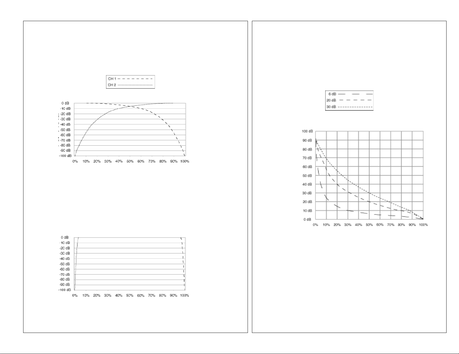
With VCA technology, audio is processed in a voltage-controlled amplifier
(VCA) removing it from the crossfader and channel slides giving them
extended life and reducing travel noise. The crossfader and channel slides
regulate the DC voltage that controls the VCA circuit. Additional
advantages of VCA technology include the ability to provide precise curve
adjustments for the crossfader and channel slides without sacrificing audio
quality. For additional information, refer to the diagrams on Page 3 for
crossfader adjustment and channel slide curve.
FeaturesFeatures
Features
FeaturesFeatures
•2 Stereo Channels
• State of the Art Cue Section with Split
•3 Phono/Line Convertible, 1 Line, and 1 Mic Input
• Adjustable Input Assign Switches
• Channel Slide Curve Control
• Crossfader with Curve Control
• Crossfader Reverse (Hamster) Switch
• Cut Feature for Low, Mid and High for each channel
• Gain, High, Mid and Low tone controls for each channel
• Mic loop
• Talkover
• Balanced and Unbalanced Master Outputs
• Zone and Record outputs
• Dual mode display
CautionsCautions
Cautions
CautionsCautions
1. All operating instructions should be read before using this equipment.
2. To reduce the risk of electrical shock, do not open the unit. There are
NO USER REPLACEABLE PARTS INSIDE. Please refer servicing to a
qualified service technician.
In the U.S.A., if you have any problems with this unit, callIn the U.S.A., if you have any problems with this unit, call
In the U.S.A., if you have any problems with this unit, call
In the U.S.A., if you have any problems with this unit, callIn the U.S.A., if you have any problems with this unit, call
1-732-969-9000 for customer service. Do not return equipment1-732-969-9000 for customer service. Do not return equipment
1-732-969-9000 for customer service. Do not return equipment
1-732-969-9000 for customer service. Do not return equipment1-732-969-9000 for customer service. Do not return equipment
1-732-738-9003
to your dealer.to your dealer.
to your dealer.
to your dealer.to your dealer.
3. Do not expose this unit to direct sunlight or to a heat source such as a
radiator or stove.
4. This unit should be cleaned only with a damp cloth. Avoid solvents or
other cleaning detergents.
5. When moving this equipment, it should be placed in its original carton
and packaging. This will reduce the risk of damage during transit.
6. DO NOT EXPOSE THIS UNIT TO RAIN OR MOISTURE.
7. DO NOT USE ANY SPRAY CLEANER OR LUBRICANT ON ANY
CONTROLS OR SWITCHES.
Height AdjustmentHeight Adjustment
Height Adjustment
Height AdjustmentHeight Adjustment
When using a UMX mixer with professional turntables, such
as the Gemini PT Series, you can make the mixer level with
the turntable by removing the mixer’s feet.
1. Place a small screw driver under the foot’s center anchor.
2. Gently pry the center anchor up and the foot will come off.
To replace the foot:
1. Place the foot on the mixer without the center anchor.
2. Replace the center anchor and push down on it to anchor the foot to
the mixer.
ConnectionsConnections
Connections
ConnectionsConnections
1. Make sure that the
comes supplied with a 18 volt AC adaptor. Plug the adaptor into the
rear panel
source.
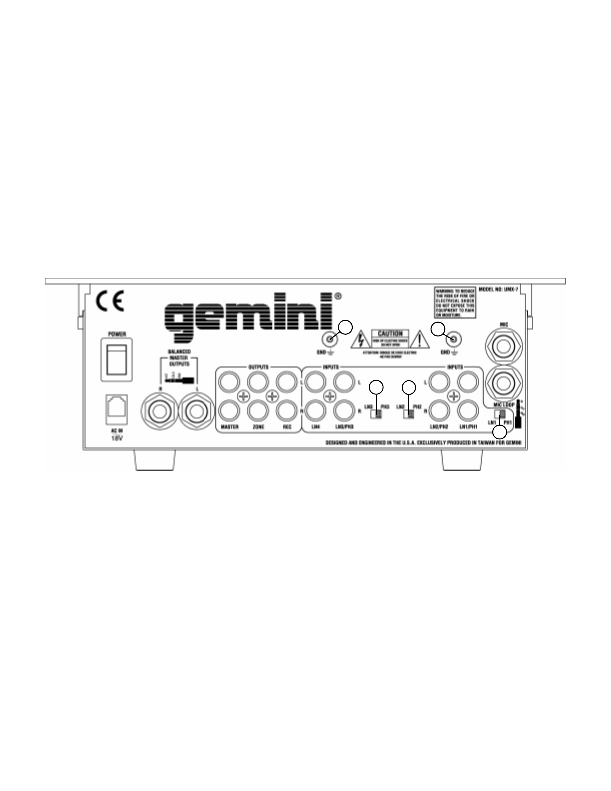
2. The UMX-7 is supplied with 4 sets of output jacks. The
MASTER OUTPUT (4)MASTER OUTPUT (4)
MASTER OUTPUT (4) jacks are used to connect to your main
MASTER OUTPUT (4)MASTER OUTPUT (4)
amplifier using standard cables with 1/4” connectors. We recommend
using the balanced amp outputs if the cables to your amp are 25 feet or
BALANCED MASTER OUTPUTSBALANCED MASTER OUTPUTS
more.
BALANCED MASTER OUTPUTS have three separate
BALANCED MASTER OUTPUTSBALANCED MASTER OUTPUTS
conductors, two of which are signal (positive and negative) and one
shield (ground). The balanced line uses a tip-ring-sleeve connection.
Tip = hot or positive (+), ring = cold or negative (-), and sleeve =
shield/ground. The
used to connect to your main amplifier. The
can be used to connect the mixer to the record input of your recorder
enabling you to record your mix. The
you to hook up an additional amplifier.
3. For your convenience, there are 2 mic inputs (located on the front panel
and the rear panel), however, only one mic input can be used at a time.
MIC (3)MIC (3)
The
MIC (3) input (found on the rear panel)
MIC (3)MIC (3)
(found on the front panel) accepts a 1/4" connector and balanced and
unbalanced microphones. The
and input for connection to an outboard signal enhancer (such as a key
controller, echo/reverb machine, etc...) using a standard balanced cable
with a 1/4” tip/ring/sleeve connector (tip = in, ring = out, and sleeve
= shield/ground).
4. On the rear panel are 3 stereo
5. Headphones can be plugged into the front panel mounted
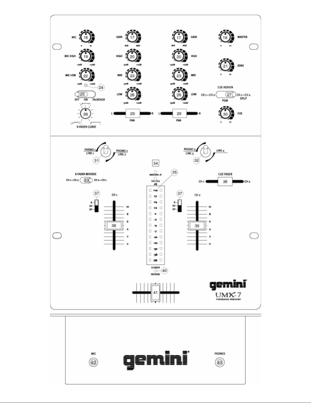
1. POWER ON: Once you have made all the equipment connections to
2. CHANNEL 1: The
3. CHANNEL 2: The
4. TONE CONTROLS: There is Low, Mid and High equalization for each
5. INPUT ASSIGN SWITCHES: You can adjust the position of the
LINE (8) LINE (8)
stereo
LINE (8) input. The
LINE (8) LINE (8)
set the
enables you to set the
SWITCHSWITCH
SWITCH
SWITCHSWITCH
phono inputs will accept only turntables with a magnetic cartridge.
GROUND SCREWS (2)GROUND SCREWS (2)
GROUND SCREWS (2) for you to ground your turntables are located
GROUND SCREWS (2)GROUND SCREWS (2)
on the rear panel. The stereo line inputs will accept any line level input
such as a CD player, a cassette player, etc.
(43)(43)
(43) jack.
(43)(43)
your mixer, press the
PAN (29)PAN (29)
PAN (29) controls allow you to fully adjust the selected source. Switch
PAN (29)PAN (29)
#
PHONO 2 (12)PHONO 2 (12)
PHONO 2 (12) input. The
PHONO 2 (12)PHONO 2 (12)
level of this channel.
PAN (29)PAN (29)
PAN (29) controls allow you to fully adjust the selected source. Switch
PAN (29)PAN (29)
#
input. The
channel.
channel with an extremely wide range of adjustment. SUGGESTION:
You can use the Cut Features on each channel to remove Low, Mid
and/or High to create special effects.
ASSIGN (31, 32)ASSIGN (31, 32)
ASSIGN (31, 32) switches to move left to right, up and down
ASSIGN (31, 32)ASSIGN (31, 32)
45 degree angle. Make these adjustments with the power OFF.
(9) (9)
(9) input to Phono or Line. The
(9) (9)
(15) (15)
(15) enables you to set the
(15) (15)
OperationOperation
Operation
OperationOperation
(31) (31)
(31) allows you to select the
(31) (31)
(32)(32)
(32) allows you to select the
(32)(32)
POWER (1)POWER (1)
POWER (1) switch is in the off position. This unit
POWER (1)POWER (1)
power jack. Then plug the adaptor into a proper power
BALANCED BALANCED
BALANCED
BALANCED BALANCED
MASTER OUTPUT (5) MASTER OUTPUT (5)
MASTER OUTPUT (5) jacks are unbalanced and
MASTER OUTPUT (5) MASTER OUTPUT (5)
MIC LOOP (14)MIC LOOP (14)
MIC LOOP (14) jack acts as an output
MIC LOOP (14)MIC LOOP (14)
PHONO/LINE (9, 12, 13) PHONO/LINE (9, 12, 13)
PHONO/LINE (9, 12, 13) inputs and 1
PHONO/LINE (9, 12, 13) PHONO/LINE (9, 12, 13)
PHONO/LINEPHONO/LINE
PHONO/LINE
PHONO/LINEPHONO/LINE
(12) (12)
(12) input to Phono or Line. The
(12) (12)
POWER (1) POWER (1)
POWER (1) switch.
POWER (1) POWER (1)
GAIN (17), HIGH (20), MID (23), LOW (26), GAIN (17), HIGH (20), MID (23), LOW (26),
GAIN (17), HIGH (20), MID (23), LOW (26), and
GAIN (17), HIGH (20), MID (23), LOW (26), GAIN (17), HIGH (20), MID (23), LOW (26),
CHANNEL CHANNEL
CHANNEL
CHANNEL CHANNEL
GAIN (17), HIGH (20), MID (23), LOW (26), GAIN (17), HIGH (20), MID (23), LOW (26),
GAIN (17), HIGH (20), MID (23), LOW (26), and
GAIN (17), HIGH (20), MID (23), LOW (26), GAIN (17), HIGH (20), MID (23), LOW (26),
CHANNEL CHANNEL
SLIDESLIDE
CHANNEL
CHANNEL CHANNEL
(39) (39)
SLIDE
(39) controls the input level of this
SLIDESLIDE
(39) (39)
(13) (13)
(13) input to Phono or Line. The
(13) (13)
LINE 1/PHONO 1 (13) LINE 1/PHONO 1 (13)
LINE 1/PHONO 1 (13) or the
LINE 1/PHONO 1 (13) LINE 1/PHONO 1 (13)
SLIDE SLIDE
SLIDE
SLIDE SLIDE
LINE 3/PHONO 3 (9) LINE 3/PHONO 3 (9)
LINE 3/PHONO 3 (9) or the
LINE 3/PHONO 3 (9) LINE 3/PHONO 3 (9)
REC OUTPUT (7) REC OUTPUT (7)
REC OUTPUT (7) jacks
REC OUTPUT (7) REC OUTPUT (7)
ZONE OUTPUT (6) ZONE OUTPUT (6)
ZONE OUTPUT (6) jacks allow
ZONE OUTPUT (6) ZONE OUTPUT (6)
OR OR
MIC (42)MIC (42)
OR the
MIC (42) input
OR OR
MIC (42)MIC (42)
SWITCHSWITCH
(10) (10)
SWITCH
(10) enables you to
SWITCHSWITCH
(10) (10)
PHONO/LINEPHONO/LINE
PHONO/LINE
PHONO/LINEPHONO/LINE
(38) (38)
(38) controls the input
(38) (38)
SWITCHSWITCH
SWITCH
SWITCHSWITCH
PHONO/LINEPHONO/LINE
PHONO/LINE
PHONO/LINEPHONO/LINE
PHONESPHONES
PHONES
PHONESPHONES
LINE 2/LINE 2/
LINE 2/
LINE 2/LINE 2/
LINE 4 (8)LINE 4 (8)
LINE 4 (8)
LINE 4 (8)LINE 4 (8)
(11) (11)
(11)
(11) (11)
OROR
OR at a
OROR
INPUTINPUT
INPUT
INPUTINPUT
Page 5
Page 6

1) Remove the channel slide, crossfader knobs and the 4 screws from
the sides of the lower face plate. Then remove the lower faceplate.
2) Remove the 2 screws in the corners of the assign switch plate.
Rotate the switch plate to the desired position, replace the screws
and tighten down.
3) To position the switch at a 45 degree angle, you need to reposition
the switch on the assign switch plate. First, remove the 2 screws in
the corners of the assign switch plate. Then, lift the switch plate up
and remove the 2 smaller screws next to the switch. Rotate the
switch plate to the right until the 45 degree holes align with the
switch holes, replace the screws and tighten down. Replace the
switch plate and tighten down.
NOTENOTE
: Keep track of where you position: Keep track of where you position
NOTE
: Keep track of where you position
NOTENOTE
: Keep track of where you position: Keep track of where you position
the input assign switches. To avoidthe input assign switches. To avoid
the input assign switches. To avoid
the input assign switches. To avoidthe input assign switches. To avoid
confusion, move the switch to a positionconfusion, move the switch to a position
confusion, move the switch to a position
confusion, move the switch to a positionconfusion, move the switch to a position
near the corresponding printing on thenear the corresponding printing on the
near the corresponding printing on the
near the corresponding printing on thenear the corresponding printing on the
faceplate.faceplate.
faceplate.
faceplate.faceplate.
6. CHANNEL SLIDE CURVE SWITCHES: Use the 3 position
SLIDE CURVE (37)SLIDE CURVE (37)
SLIDE CURVE (37) switches to adjust the kind of curve the channel
SLIDE CURVE (37)SLIDE CURVE (37)
slides have. Move the selected channel slide curve switch to the 6 (top)
position to make the increase in level gradual and even. Move the
channel slide curve switch to the 20 (center) position to make the
increase in level less gradual as you move channel slide up. Move the
channel slide curve switch to the 30 (bottom) position to make the
increase in level even less gradual, especially at the top of the slide.
7. CROSSFADER SECTION: The
of one source into another. The left side of the
CHANNEL 1 and the right side is CHANNEL 2. The
CURVE (28)CURVE (28)
CURVE (28) control allows you to adjust the kind of curve the
CURVE (28)CURVE (28)
crossfader has. Move the
right to make the curve steep and cutting (perfect for scratching). Move
CROSSFADER CURVE (28)CROSSFADER CURVE (28)
the
CROSSFADER CURVE (28) control to the left to make the curve
CROSSFADER CURVE (28)CROSSFADER CURVE (28)
gradual and gentle. The
allows you to reverse the crossfader so that CHANNEL 2 is controlled
by the left side of the crossfader and CHANNEL 1 is controlled by the
right side of the crossfader. When REVERSE is activated the
LED (40)LED (40)
LED (40) will light.
LED (40)LED (40)
NOTE: When the CROSSFADER REVERSE SWITCH (33) is activatedNOTE: When the CROSSFADER REVERSE SWITCH (33) is activated
NOTE: When the CROSSFADER REVERSE SWITCH (33) is activated
NOTE: When the CROSSFADER REVERSE SWITCH (33) is activatedNOTE: When the CROSSFADER REVERSE SWITCH (33) is activated
(moved to the right), only the crossfader reverses. The Channel Slides,(moved to the right), only the crossfader reverses. The Channel Slides,
(moved to the right), only the crossfader reverses. The Channel Slides,
(moved to the right), only the crossfader reverses. The Channel Slides,(moved to the right), only the crossfader reverses. The Channel Slides,
Gain and tonal controls do not reverse.Gain and tonal controls do not reverse.
Gain and tonal controls do not reverse.
Gain and tonal controls do not reverse.Gain and tonal controls do not reverse.
8. OUTPUT CONTROL SECTION: The level of the
(4, 5)(4, 5)
(4, 5) is controlled by the
(4, 5)(4, 5)
control adjusts the level of the
output is used by some DJs to run monitor speakers in their DJ booth.
You can also use it as a second ZONE or AMP output.
NOTE: The RECORD OUT (7) has no level control. The level is set by theNOTE: The RECORD OUT (7) has no level control. The level is set by the
NOTE: The RECORD OUT (7) has no level control. The level is set by the
NOTE: The RECORD OUT (7) has no level control. The level is set by theNOTE: The RECORD OUT (7) has no level control. The level is set by the
channel slides and the gain controls of the selected channel. The tonalchannel slides and the gain controls of the selected channel. The tonal
channel slides and the gain controls of the selected channel. The tonal
channel slides and the gain controls of the selected channel. The tonalchannel slides and the gain controls of the selected channel. The tonal
qualities are set by the low, mid and high controls of that same channel.qualities are set by the low, mid and high controls of that same channel.
qualities are set by the low, mid and high controls of that same channel.
qualities are set by the low, mid and high controls of that same channel.qualities are set by the low, mid and high controls of that same channel.
9. MIC CONTROLS: The purpose of the talkover section is to allow the
program playing to be muted so that the mic can be heard above the
music. The
MIC/TALKOVER (25)MIC/TALKOVER (25)
MIC/TALKOVER (25) switch is in the left position, the mic and
MIC/TALKOVER (25)MIC/TALKOVER (25)
talkover are both off. When the
center position the mic is on, the
talkover is off. When the
position, the mic and talkover will be on and the volume of all sources
except the Mic input are lowered by 16 dB.
the level of the MIC. The MIC EQ controls,
LOW (22)LOW (22)
LOW (22), allow you to fully adjust the tone of the MIC.
LOW (22)LOW (22)
10. CUE SECTION: By connecting a set of headphones to the
(43)(43)
(43) jack, you can monitor the program output, each channel
(43)(43)
individually or both channels together. The
you to select what to monitor and has 3 positions. Move the
ASSIGN (27)ASSIGN (27)
ASSIGN (27) to the left to monitor CHANNEL 1 and CHANNEL 2 in
ASSIGN (27)ASSIGN (27)
stereo. Move the
the program (PGM) output. Move the
to split the signals from each channel so that CHANNEL 1 will be
MIC/TALKOVER (25)MIC/TALKOVER (25)
MIC/TALKOVER (25)
MIC/TALKOVER (25)MIC/TALKOVER (25)
CUE ASSIGN (27)CUE ASSIGN (27)
CUE ASSIGN (27) to the center position to monitor
CUE ASSIGN (27)CUE ASSIGN (27)
CROSSFADER (41)CROSSFADER (41)
CROSSFADER (41) allows the mixing
CROSSFADER (41)CROSSFADER (41)
CROSSFADER CURVE (28)CROSSFADER CURVE (28)
CROSSFADER CURVE (28) control to the
CROSSFADER CURVE (28)CROSSFADER CURVE (28)
CROSSFADER REVERSE SWITCH (33)CROSSFADER REVERSE SWITCH (33)
CROSSFADER REVERSE SWITCH (33)
CROSSFADER REVERSE SWITCH (33)CROSSFADER REVERSE SWITCH (33)
MASTER (18) MASTER (18)
MASTER (18) control. The
MASTER (18) MASTER (18)
ZONE OUTPUT (6)ZONE OUTPUT (6)
ZONE OUTPUT (6).
ZONE OUTPUT (6)ZONE OUTPUT (6)
switch
has three settings. When the
MIC/TALKOVER (25)MIC/TALKOVER (25)
MIC/TALKOVER (25) switch is in the
MIC/TALKOVER (25)MIC/TALKOVER (25)
MIC INDICATOR (24)MIC INDICATOR (24)
MIC INDICATOR (24) will glow, but
MIC/TALKOVER (25)MIC/TALKOVER (25)
MIC/TALKOVER (25) switch is in the right
MIC/TALKOVER (25)MIC/TALKOVER (25)
MIC INDICATOR (24)MIC INDICATOR (24)
CUE ASSIGN (27)CUE ASSIGN (27)
CUE ASSIGN (27) to the right
CUE ASSIGN (27)CUE ASSIGN (27)
CROSSFADER (41) CROSSFADER (41)
CROSSFADER (41) is
CROSSFADER (41) CROSSFADER (41)
MASTER OUTPUTMASTER OUTPUT
MASTER OUTPUT
MASTER OUTPUTMASTER OUTPUT
HINT: The zone
MIC LEVEL (16)MIC LEVEL (16)
MIC LEVEL (16) controls
MIC LEVEL (16)MIC LEVEL (16)
MIC HIGH (19) MIC HIGH (19)
MIC HIGH (19) and
MIC HIGH (19) MIC HIGH (19)
CUE ASSIGN (27)CUE ASSIGN (27)
CUE ASSIGN (27) allows
CUE ASSIGN (27)CUE ASSIGN (27)
CHANNELCHANNEL
CHANNEL
CHANNELCHANNEL
CROSSFADERCROSSFADER
CROSSFADER
CROSSFADERCROSSFADER
REVERSEREVERSE
REVERSE
REVERSEREVERSE
ZONE (21)ZONE (21)
ZONE (21)
ZONE (21)ZONE (21)
PHONESPHONES
PHONES
PHONESPHONES
CUECUE
CUE
CUECUE
MICMIC
MIC
MICMIC
heard in one earphone and CHANNEL 2 will be heard in the other
earphone. While the
(the CHANNEL 1 and CHANNEL 2 combinations), move the
FADER (36)FADER (36)
FADER (36) to the left to isolate CHANNEL 1 and to the right to isolate
FADER (36)FADER (36)
CHANNEL 2. Move the
channels together (split or in stereo).
11. DISPLAY: The peak hold, dual function
MASTERMASTER
the
MASTER output left and right levels or the channel 1 and channel
MASTERMASTER
2 levels. You can choose the option you want by pressing the
(34)(34)
(34) button.
(34)(34)
NOTE: When the DISPLAY (35) is in the channel 1/channel 2 displayNOTE: When the DISPLAY (35) is in the channel 1/channel 2 display
NOTE: When the DISPLAY (35) is in the channel 1/channel 2 display
NOTE: When the DISPLAY (35) is in the channel 1/channel 2 displayNOTE: When the DISPLAY (35) is in the channel 1/channel 2 display
mode, by adjusting the individual channel gain and tone controls, you canmode, by adjusting the individual channel gain and tone controls, you can
mode, by adjusting the individual channel gain and tone controls, you can
mode, by adjusting the individual channel gain and tone controls, you canmode, by adjusting the individual channel gain and tone controls, you can
increase or decrease the signal to match the other channel’s signal. Theincrease or decrease the signal to match the other channel’s signal. The
increase or decrease the signal to match the other channel’s signal. The
increase or decrease the signal to match the other channel’s signal. Theincrease or decrease the signal to match the other channel’s signal. The
channel slides and crossfader have no effect on the display readings.channel slides and crossfader have no effect on the display readings.
channel slides and crossfader have no effect on the display readings.
channel slides and crossfader have no effect on the display readings.channel slides and crossfader have no effect on the display readings.
SpecificationsSpecifications
Specifications
SpecificationsSpecifications
INPUTS:
DJ Mic....................................................1.5mV 2Kohm balanced
Phono.........................................................................3mV 47Kohm
Line.......................................................................150 mV 27Kohm
OUTPUTS:
Master (balanced)...........................................0 dB 2 V 800 Ohm
Master/Zone (unbalanced)...................................0 dB 1V 400ohm
Rec...........................................................................225mV 5Kohm
MIC:
DJ Mic....................................................1.5mV 2Kohm balanced
Bass......................................................................................± 12dB
High.......................................................................................± 12dB
GENERAL:
Low............................................................................+ 12dB/- 32 dB
Mid............................................................................+ 12dB/- 32 dB
High..........................................................................+ 12dB/- 32 dB
Gain...........................................................................0 to -20dB
Frequency Response....................................20Hz - 20KHz +/- 2dB
Distortion................................................................................0.08%
S/N Ratio...............................................................better than 80dB
Talkover Attenuation..............................................................-16dB
Headphone Impedance.........................................................16ohm
Power Source.............................................115V/18V AC 0.75A
Dimensions...................................10”w x 14”h x 4.33”d (254 x 355 x 110 mm)
Weight...........................................................................6.5 lbs (3 kg)
CUE ASSIGN (27)CUE ASSIGN (27)
CUE ASSIGN (27) is in the left or right positions
CUE ASSIGN (27)CUE ASSIGN (27)
CUE FADER (36)CUE FADER (36)
CUE FADER (36) to the center to listen to both
CUE FADER (36)CUE FADER (36)
DISPLAY (35)DISPLAY (35)
DISPLAY (35) indicates either
DISPLAY (35)DISPLAY (35)
Max.............................40 V Peak to Peak
Max..............................20V Peak to Peak
230V/18V AC 0.75A
CUECUE
CUE
CUECUE
DISPLAY DISPLAY
DISPLAY
DISPLAY DISPLAY
Page 6
Page 7

EinleitungEinleitung
Einleitung
EinleitungEinleitung
Wir gratulieren Ihnen zum Kauf eines Gemini UMX-7 VCA Mischpults.
Dieses moderne Mischpult enthält eine dreijährige Garantie,
ausgenommen Crossfader und Kanalfader. Vor Anwendung dieses
Mischpults bitte alle Anweisungen sorgfältig durchlesen.
Mit der VCA-Technologie wird das Audiosignal in einem
spannungsregulierten Verstärker (Voltage Controlled Amplifier) bearbeitet
und nicht über Cross- oder Kanalfader geführt, was zu einer erhöhten
Lebensdauer und geringeren Fadergeräuschen führt. Die Cross- und
Kanalfader regulieren eine Gleichstromspannung, die wiederum die VCASchaltung steuert. Ein weiterer Vorteil der VCA-Technologie ist die
Möglichkeit zur präzisen Kurvensteuerung von Cross- und Kanalfadern
ohne die Qualität des Audiosignals zu beeinflussen. Weitere Informationen
finden Sie im Diagramm auf Seite 3, das die Crossfader-Regulierung und
die Kanalfaderkurve darstellt.
FunktionenFunktionen
Funktionen
FunktionenFunktionen
•2 Stereokanäle
• Aufwendige Vorhörsektion mit Split-Schalter
•3 Phono-/Line (umschaltbar), 2 Line und 1 Mikrophon Eingang
• Verstellbare Eingangs-Zuweisungsschalter
• Kanalfaderkurven-Steuerung
• Crossfader mit Kurvensteuerung
• Crossfader-Reverse (Hamster) Schalter
• CUT-Equalizer Funktion für Bässe, Mitten- und Höhen pro Kanal
• MIC-Effekteinschleifweg (Loop)
• Talkover
• Symmetrische und unsymmetrische Master-Ausgänge
• Zonen und Aufnahme Ausgänge
• Umschaltbares VU-Meter
VorsichtsmaßnahmenVorsichtsmaßnahmen
Vorsichtsmaßnahmen
VorsichtsmaßnahmenVorsichtsmaßnahmen
1. Vor Anwendung dieses Geräts bitte alle Anweisungen sorgfältig
durchlesen.
2. Das Gerät nicht öffnen, um das Risiko elektrischen Schocks zu
vermeiden. Es enthält KEINE VOM ANWENDER ERSETZBAREN
TEILE. Die Wartung darf nur von authorisierten Wartungstechnikern
durchgeführt werden.
3. Das Gerät keinem direkten Sonnenlicht oder einer Wärmequelle wie
Heizkörper oder Ofen aussetzen.
4. Dieses Gerät darf nur mit einem feuchten Tuch gesäubert werden.
Keine Lösungs- oder Reinigungsmittel benutzen.
5.Bei Umzügen sollte das Gerät in seinem ursprünglichen Versandkarton
und Verpackungsmaterial verpackt werden. Dadurch verhindert man,
daß das Gerät während des Transportes beschädigt wird.
6. DIESES GERÄT NICHT REGEN ODER FEUCHTIGKEIT AUSSETZEN.
7. AN DEN REGLERN ODER SCHALTERN KEIN SPRAYREINIGUNGSMITTEL ODER SCHMIERMITTEL BENUTZEN.
Um den Fuß wieder einzusetzen:
1. Den Fuß ohne den mittleren Stift in den Mixer drücken.
2. Den mittleren Stift einsetzen und fest eindrücken, um den Fuß im
Mixer zu verankern.
AnschlüsseAnschlüsse
Anschlüsse
AnschlüsseAnschlüsse
1. Darauf achten, daß der Netzschalter
geschaltet ist. Dieses Gerät wird mit einem 18-V-Wechselstromadapter
geliefert. Den Adapter in die Leistungsbuchse an der Rückwand
stecken. Dann den Adapter an der vorschriftsmässigen Stromquelle
anschliessen.
2. Der UMX-7 verfügt über 4 Ausgangsbuchsenpaare. Die Buchsen
BALANCED MASTER OUTPUT (4)BALANCED MASTER OUTPUT (4)
BALANCED MASTER OUTPUT (4) dienen zum Anschluß an den
BALANCED MASTER OUTPUT (4)BALANCED MASTER OUTPUT (4)
Hauptverstärker, wofür Standard 6,3mm-Stereo-Klinken-Kabel benutzt
werden. Wir empfehlen, die symmetrischen Master-Ausgänge zu
benutzen, wenn die Kabel zu Ihrem Verstärker 3 m oder länger sind.
Symmetrische Ausgänge haben drei (3) verschiedene Leiter: zwei für
Signal (positiv und negativ) und einen für Masse. Die symmetrische
Leitung benutzt eine Spitzen-Ring-Muffen-Verbindung. Spitze = heiß
bzw. plus (+), Ring = kalt bzw. minus (-) und Muffe = Abschirmung/
Masse. Die Buchsen (
dienen zum Anschluß an einen Hauptverstärker ohne symmetrischen
Eingang. Die Buchsen
Mischpult an den Aufnahmeeingang des Aufnahmegerätes
anzuschließen, um die Tonmischung aufnehmen zu können. Die
Buchsen
zusätzlichen Verstärker (z.B. für Monitorzwecke).
3. Zum einfachen Anschluß sind 2 MIC-Eingänge (an der Vorder- und
Rückseite) angebracht, wobei jedoch jeweils nur ein MIC-Eingang
benutzt werden kann. Der Eingang
der Eingang
Klinkenstecker sowie symmetrische und unsymmetrische Mikrofone
auf. Die Buchse für den
Eingang zum Anschluß an einen beliebigen Soundprozessor (wie z.B.
Tonhöhen-Controller, Echo/Hall-Gerät, usw. ...), wobei ein
symmetrisches Stereo-Klinken-Kabel mit 6,3mm mm Spitze/Ring/
Steckverbindung (Spitze = Eingang, Ring = Ausgang und Muffe =
Masse) verwendet wird.
4. An der Rückwand sind jeweils 3 Stereoeingänge
13)13)
13) und 1 Stereoeingang
13)13)
ermöglicht Ihnen, die Eingänge
umzuschalten. Der Schalter
Eingänge
PHONO/LINE (15)PHONO/LINE (15)
PHONO/LINE (15) ermöglicht Ihnen, die Eingänge
PHONO/LINE (15)PHONO/LINE (15)
Phono oder Line umzuschalten. Die Phono-Eingänge sind
ausschließlich für Plattenspieler mit einem magnetischem
Tonabnehmer zu verwenden. Erdungschrauben -
(2)(2)
(2) zur Erdung des Plattenspielers sind an der Rückwand angebracht. .
(2)(2)
Die Stereo-Line-Eingänge sind für den Anschluß von CD-, MD- oder
Kassettengeräten vorgesehen.
5. Ein Kopfhörer kann an der Kopfhörer-Buchse
Vorderseite eingesteckt werden.
ZONE OUTPUT (6)ZONE OUTPUT (6)
ZONE OUTPUT (6) ermöglichen den Anschluß an einen
ZONE OUTPUT (6)ZONE OUTPUT (6)
MIC (42)MIC (42)
MIC (42) (an der Vorderseite) nimmt einen 6,3mm
MIC (42)MIC (42)
(12)(12)
(12) zwischen Phono oder Line umzuschalten. Der Schalter
(12)(12)
BedienungBedienung
Bedienung
BedienungBedienung
MASTER OUTPUT )MASTER OUTPUT )
MASTER OUTPUT ) sind unsymmetrisch und
MASTER OUTPUT )MASTER OUTPUT )
REC OUTPUT (7)REC OUTPUT (7)
REC OUTPUT (7) können dazu dienen, das
REC OUTPUT (7)REC OUTPUT (7)
MIC-EFFEKTWEG (14) MIC-EFFEKTWEG (14)
MIC-EFFEKTWEG (14) dient als Ausgang und
MIC-EFFEKTWEG (14) MIC-EFFEKTWEG (14)
LINE (8)LINE (8)
LINE (8). Der Schalter
LINE (8)LINE (8)
PHONO/LINE (11) PHONO/LINE (11)
PHONO/LINE (11) ermöglicht Ihnen, die
PHONO/LINE (11) PHONO/LINE (11)
POWER (1)POWER (1)
POWER (1) in Off-Position
POWER (1)POWER (1)
MIC (3)MIC (3)
MIC (3) (an der Rückseite)
MIC (3)MIC (3)
PHONO/LINE (9, 12,PHONO/LINE (9, 12,
PHONO/LINE (9, 12,
PHONO/LINE (9, 12,PHONO/LINE (9, 12,
PHONO/LINE (10) PHONO/LINE (10)
PHONO/LINE (10)
(9)(9)
(9) zwischen Phono oder Line
(9)(9)
PHONO/LINE (10) PHONO/LINE (10)
(13)(13)
(13) zwischen
(13)(13)
GROUND SCREWSGROUND SCREWS
GROUND SCREWS
GROUND SCREWSGROUND SCREWS
PHONES (43)PHONES (43)
PHONES (43) auf der
PHONES (43)PHONES (43)
ODER
ODERODER
ODERODER
HöhenjustierungHöhenjustierung
Höhenjustierung
HöhenjustierungHöhenjustierung
Wenn man einen UMX Mixer zusammen mit professionellen
Plattenspielern wie Gemini PT Serie benutzen möchte, kann
man die gleiche Gerätehöhe der Plattenspieler erreichen,
indem man die Füße des Mixers entfernt.
1. Mit einem kleinen Schraubenzieher den mittleren Stift des
Fußes heraushebeln.
2. Vorsichtig den Stift abnehmen und den Fuß herausziehen.
1. NETZ EINSCHALTEN : Nachdem Sie alle Tonquellen am Mischpult
angeschlossen haben, drücken Sie auf die Taste
2. KANAL 1: Die Regelelemente
(26), (26),
(26), und
(26), (26),
Regulieren der ausgewählten Tonquelle. Schalter
Eingang von
auszuwählen.
Kanals.
3. KANAL 2: Die Regelelemente
(26), (26),
(26), und
(26), (26),
Regulieren der ausgewählten Tonquelle. Schalter #
Page 7
PAN (29)PAN (29)
PAN (29) (Balance) ermöglichen ein vollkommenes
PAN (29)PAN (29)
PAN (29)PAN (29)
PAN (29) (Balance) ermöglichen ein vollkommenes
PAN (29)PAN (29)
LINE 1/PHONO 1 (13)LINE 1/PHONO 1 (13)
LINE 1/PHONO 1 (13) oder
LINE 1/PHONO 1 (13)LINE 1/PHONO 1 (13)
CHANNEL SLIDE (38)CHANNEL SLIDE (38)
CHANNEL SLIDE (38) regelt den Ausgangspegel dieses
CHANNEL SLIDE (38)CHANNEL SLIDE (38)
GAIN (17), HIGH (20), MID (23), LOWGAIN (17), HIGH (20), MID (23), LOW
GAIN (17), HIGH (20), MID (23), LOW
GAIN (17), HIGH (20), MID (23), LOWGAIN (17), HIGH (20), MID (23), LOW
GAIN (17), HIGH (20), MID (23), LOWGAIN (17), HIGH (20), MID (23), LOW
GAIN (17), HIGH (20), MID (23), LOW
GAIN (17), HIGH (20), MID (23), LOWGAIN (17), HIGH (20), MID (23), LOW
POWER (1)POWER (1)
POWER (1).
POWER (1)POWER (1)
(31)(31)
(31) ermöglicht, den
(31)(31)
LINE 2/PHONO 2 (12) LINE 2/PHONO 2 (12)
LINE 2/PHONO 2 (12)
LINE 2/PHONO 2 (12) LINE 2/PHONO 2 (12)
(32)(32)
(32) ermöglicht, den
(32)(32)
Page 8

Eingang von
CHANNEL SLIDE (39)CHANNEL SLIDE (39)
CHANNEL SLIDE (39) regelt den Ausgangspegel dieses Kanals.
CHANNEL SLIDE (39)CHANNEL SLIDE (39)
4. KLANGREGLER: Für jeden Kanal gibt es separate Bass- (Low), Mitten(Mid) und Höhen- (High) Regler mit einem äusserst breiten
Regulierbereich, die eine flexible Mischung bieten. PROFI-TIP: Sie
können die CUT Funktion eines jeden Kanals benutzen, um Low, Mid
und/oder High auszublenden um dadurch Spezialeffekte zu erzielen.
5. EINGANGSZUWEISUNGSSCHALTER: Sie können die Position der
INPUT ASSIGN (31, 32)INPUT ASSIGN (31, 32)
INPUT ASSIGN (31, 32) Schalter ändern, wenn Sie die Schalter von
INPUT ASSIGN (31, 32)INPUT ASSIGN (31, 32)
links nach rechts und von oben nach unten
45 Grad bedienen möchten. Diese Einstellungen werden
vorgenommen, wenn der Netzschalter in OFF-Position steht.
1) Die Kanalfader-, die Crossfaderknöpfe von den Fadern und die 4
Schrauben der unteren Frontplatte entfernen. Dann die untere
Frontplatte entfernen.
2) Die 2 Schrauben an den Ecken der Zuweisungs-Schalterplatte
entfernen. Die Schalterplatte in die gewünschte Position drehen, die
Schrauben wieder einsetzen und festziehen.
3) Um den Schalter in einen Winkel von 45 Grad zu positionieren, den
Schalter auf der Zuweisungs-Schalterplatte umpositionieren. Dann
die Schalterplatte anheben und die 2 kleineren Schrauben neben
dem Schalter entfernen. Die Schalterplatte nach rechts drehen, bis
die Löcher im Winkel von 45 Grad mit den Schalterlöchern
ausgerichtet sind, die Schrauben wieder einsetzen und festziehen.
Die Schalterplatte wieder
aufsetzen und festschrauben.
HINWEISHINWEIS
: Darauf achten, wo Sie die: Darauf achten, wo Sie die
HINWEIS
: Darauf achten, wo Sie die
HINWEISHINWEIS
: Darauf achten, wo Sie die: Darauf achten, wo Sie die
EingangszuweisungsschalterEingangszuweisungsschalter
Eingangszuweisungsschalter
EingangszuweisungsschalterEingangszuweisungsschalter
positionieren. Um Verwirrung zupositionieren. Um Verwirrung zu
positionieren. Um Verwirrung zu
positionieren. Um Verwirrung zupositionieren. Um Verwirrung zu
vermeiden, müssen die Schalter in einevermeiden, müssen die Schalter in eine
vermeiden, müssen die Schalter in eine
vermeiden, müssen die Schalter in einevermeiden, müssen die Schalter in eine
Position in der Nähe desPosition in der Nähe des
Position in der Nähe des
Position in der Nähe desPosition in der Nähe des
entsprechenden Aufdrucks derentsprechenden Aufdrucks der
entsprechenden Aufdrucks der
entsprechenden Aufdrucks derentsprechenden Aufdrucks der
Frontplatte geschoben werden.Frontplatte geschoben werden.
Frontplatte geschoben werden.
Frontplatte geschoben werden.Frontplatte geschoben werden.
6. KANALFADERKURVEN -SCHALTER: Die 3
CURVE (37)CURVE (37)
CURVE (37) Positionschalter benutzen, um die Kurvenart der
CURVE (37)CURVE (37)
Kanalfader einzustellen. Den gewählten Kanalfaderkurven-Schalter in
Position 6 (oben) schieben, um einen allmählichen und sanften
Signalpegelanstieg zu ermöglichen. Den Kanalfaderkurven-Schalter in
Position 20 (Mitte) schieben, um einen weniger sanften
Signalpegelanstieg zu ermöglichen, wenn der Kanal aufwärts
geschoben wird. Den Kanalfaderkurven-Schalter in Position 30 (unten)
schieben, um einen schnell zunehmenden Signalpegelanstieg zu
ermöglichen, besonders am oberen Ende des Faders.
7. CROSSFADER: Der Überblender
Mischen von Tonquellen. Die linke Seite des
KANAL 1 und die rechte ist KANAL 2. Die
(28)(28)
(28) Steuerung ermöglicht Ihnen, die Kurven des Überblenders
(28)(28)
einzustellen. Die
verschieben, um eine steile und schneidende Kurve zu erzielen (ideal
für Scratching). Die
verschieben, um eine allmählich ansteigende und sanfte Kurve zu
erzielen. Der
seitenverkehrten Betrieb des Crossfaders Kanal 2 wird nun kontrolliert
durch die linke Seite des Crossfader und Kanal 1 durch die rechte Seite.
Ist der Reverse aktiviert, dann leuchtet der
HINWEIS: Ist der CROSSFADER REVERSE-SCHALTER (33) aktiviertHINWEIS: Ist der CROSSFADER REVERSE-SCHALTER (33) aktiviert
HINWEIS: Ist der CROSSFADER REVERSE-SCHALTER (33) aktiviert
HINWEIS: Ist der CROSSFADER REVERSE-SCHALTER (33) aktiviertHINWEIS: Ist der CROSSFADER REVERSE-SCHALTER (33) aktiviert
(nach rechts geschoben), läuft nur der Überblender in Gegenrichtung. (nach rechts geschoben), läuft nur der Überblender in Gegenrichtung.
(nach rechts geschoben), läuft nur der Überblender in Gegenrichtung. Die
(nach rechts geschoben), läuft nur der Überblender in Gegenrichtung. (nach rechts geschoben), läuft nur der Überblender in Gegenrichtung.
KanalfaderKanalfader
Kanalfader, Vorpegelregler und Tonregler werden hier von nicht beeinflusst.
KanalfaderKanalfader
8. AUSGANGSREGELUNG: Der Pegel des
(Verstärkerausgang) des Drehreglers
Regler
EMPFEHLUNG: Die
um die Lautsprecher in der DJ-Kabine separat zu überwachen.
Ebenfalls kann es als zweiter Verstärker -Ausgang benutzt werden.
HINWEIS: RECORD OUT (7) verfügt über keinen eigenen Pegelregler. DerHINWEIS: RECORD OUT (7) verfügt über keinen eigenen Pegelregler. Der
HINWEIS: RECORD OUT (7) verfügt über keinen eigenen Pegelregler. Der
HINWEIS: RECORD OUT (7) verfügt über keinen eigenen Pegelregler. DerHINWEIS: RECORD OUT (7) verfügt über keinen eigenen Pegelregler. Der
Pegel wird durch die Kanalfader und die Vorpegelregler des ausgewähltenPegel wird durch die Kanalfader und die Vorpegelregler des ausgewählten
Pegel wird durch die Kanalfader und die Vorpegelregler des ausgewählten
Pegel wird durch die Kanalfader und die Vorpegelregler des ausgewähltenPegel wird durch die Kanalfader und die Vorpegelregler des ausgewählten
Kanals beeinflusst. Die Tonqualität wird durch die Tiefen-, Höhen, undKanals beeinflusst. Die Tonqualität wird durch die Tiefen-, Höhen, und
Kanals beeinflusst. Die Tonqualität wird durch die Tiefen-, Höhen, und
Kanals beeinflusst. Die Tonqualität wird durch die Tiefen-, Höhen, undKanals beeinflusst. Die Tonqualität wird durch die Tiefen-, Höhen, und
Mittelbereichsregler dieses Kanals eingestellt.Mittelbereichsregler dieses Kanals eingestellt.
Mittelbereichsregler dieses Kanals eingestellt.
Mittelbereichsregler dieses Kanals eingestellt.Mittelbereichsregler dieses Kanals eingestellt.
LINE 3/PHONO 3 (9) LINE 3/PHONO 3 (9)
LINE 3/PHONO 3 (9) oder
LINE 3/PHONO 3 (9) LINE 3/PHONO 3 (9)
CROSSFADER CURVE (28)CROSSFADER CURVE (28)
CROSSFADER CURVE (28) Steuerung nach rechts
CROSSFADER CURVE (28)CROSSFADER CURVE (28)
CROSSFADER CURVE (28)CROSSFADER CURVE (28)
CROSSFADER CURVE (28) Steuerung nach links
CROSSFADER CURVE (28)CROSSFADER CURVE (28)
CROSSFADER REVERSE SWITCH (33) CROSSFADER REVERSE SWITCH (33)
CROSSFADER REVERSE SWITCH (33) ermöglicht den
CROSSFADER REVERSE SWITCH (33) CROSSFADER REVERSE SWITCH (33)
ZONE (21)ZONE (21)
ZONE (21) justiert den Pegel des
ZONE (21)ZONE (21)
ZONE OUTPUTZONE OUTPUT
ZONE OUTPUT wird von einigen DJs benutzt,
ZONE OUTPUTZONE OUTPUT
LINE 4 (8) LINE 4 (8)
LINE 4 (8) auszuwählen.
LINE 4 (8) LINE 4 (8)
ODER ODER
ODER in einem Winkel von
ODER ODER
CHANNEL SLIDECHANNEL SLIDE
CHANNEL SLIDE
CHANNEL SLIDECHANNEL SLIDE
CROSSFADER (41)CROSSFADER (41)
CROSSFADER (41) ermöglicht das
CROSSFADER (41)CROSSFADER (41)
MASTER (18)MASTER (18)
MASTER (18) gesteuert. Der
MASTER (18)MASTER (18)
CROSSFADERS (41)CROSSFADERS (41)
CROSSFADERS (41) ist
CROSSFADERS (41)CROSSFADERS (41)
CROSSFADER CURVECROSSFADER CURVE
CROSSFADER CURVE
CROSSFADER CURVECROSSFADER CURVE
REVERSE LED (40)REVERSE LED (40)
REVERSE LED (40).
REVERSE LED (40)REVERSE LED (40)
MASTER OUTPUT (4, 5)MASTER OUTPUT (4, 5)
MASTER OUTPUT (4, 5)
MASTER OUTPUT (4, 5)MASTER OUTPUT (4, 5)
ZONE OUTPUT (6)ZONE OUTPUT (6)
ZONE OUTPUT (6).
ZONE OUTPUT (6)ZONE OUTPUT (6)
9. MIKROFONREGLER: Durch die Talkover-Funktion wird das
abgespielte Programm gedämpft, um eine Ansage über das Mikrophon
hören zu können. Der Schalter
Einstellungen. Wenn der Schalter
Position steht, sind MIC und Talkover beide ausgeschaltet. Steht der
Schalter
eingeschaltet. Der
ausgeschaltet. Wenn der Schalter
Position steht, sind MIC und Talkover eingeschaltet, und Lautstärken
aller Tonquellen, außer des MIC-Eingangs, werden um 16 dB reduziert.
MIC LEVEL (16)MIC LEVEL (16)
MIC LEVEL (16) reguliert die Tonstärke von MIC. Die MIC EQ Regler,
MIC LEVEL (16)MIC LEVEL (16)
MIC HIGH (19) MIC HIGH (19)
MIC HIGH (19) und
MIC HIGH (19) MIC HIGH (19)
von MIC vollständig zu regulieren.
10. VORHÖR SEKTION: Den Kopfhörer an der KOPFHÖRER-Buchse
PHONES (43) PHONES (43)
PHONES (43) anschliessen um den Masterausgang (PGM), einen oder
PHONES (43) PHONES (43)
beide Kanäle vorzuhören. Der CUE-SCHALTER mit 3 Positionen macht es möglich eine Auswahl zu treffen. Indem Sie
den
und den KANAL 2 in Stereo vorhören. Schieben Sie den
(27)(27)
(27) zur Mitte um den Masterausgang (PGM) zu hören. Stellen Sie den
(27)(27)
CUE ASSIGN (27)CUE ASSIGN (27)
CUE ASSIGN (27) nach rechts um Kanal 1 und Kanal 2 getrennt von
CUE ASSIGN (27)CUE ASSIGN (27)
einander in je einer Kopfhörermuschel zu hören. Während der
ASSIGN (27)ASSIGN (27)
ASSIGN (27) rechts oder links steht, schieben Sie den
ASSIGN (27)ASSIGN (27)
nach links um den KANAL 1 zu isolieren und nach rechts um den
KANAL 2 zu isolieren. Schieben Sie den
um beide Kanäle zu hören (getrennt oder in Stereo).
11. ANZEIGEN: Die Doppelfunktionsanzeige
Darstellung entweder der Pegel des
rechts oder der Pegel der Kanäle 1 und 2. Die gewünschte Option kann
durch Druck auf die Taste
Zu beachten: Wenn das DISPLAY (35) sich im Anzeigemodus Kanal 1/Zu beachten: Wenn das DISPLAY (35) sich im Anzeigemodus Kanal 1/
Zu beachten: Wenn das DISPLAY (35) sich im Anzeigemodus Kanal 1/
Zu beachten: Wenn das DISPLAY (35) sich im Anzeigemodus Kanal 1/Zu beachten: Wenn das DISPLAY (35) sich im Anzeigemodus Kanal 1/
Kanal 2 befindet, kann das Signal mittels der einzelnenKanal 2 befindet, kann das Signal mittels der einzelnen
Kanal 2 befindet, kann das Signal mittels der einzelnen
Kanal 2 befindet, kann das Signal mittels der einzelnenKanal 2 befindet, kann das Signal mittels der einzelnen
Verstärkungsfaktor- und Toneinstellungen verstärkt oder verringertVerstärkungsfaktor- und Toneinstellungen verstärkt oder verringert
Verstärkungsfaktor- und Toneinstellungen verstärkt oder verringert
Verstärkungsfaktor- und Toneinstellungen verstärkt oder verringertVerstärkungsfaktor- und Toneinstellungen verstärkt oder verringert
werden, um es dem Signal des anderen Signals anzupassen. Diewerden, um es dem Signal des anderen Signals anzupassen. Die
werden, um es dem Signal des anderen Signals anzupassen. Die
werden, um es dem Signal des anderen Signals anzupassen. Diewerden, um es dem Signal des anderen Signals anzupassen. Die
Kanalschieber und der Überblender haben keinen Einfluß auf dieKanalschieber und der Überblender haben keinen Einfluß auf die
Kanalschieber und der Überblender haben keinen Einfluß auf die
Kanalschieber und der Überblender haben keinen Einfluß auf dieKanalschieber und der Überblender haben keinen Einfluß auf die
Anzeigewerte.Anzeigewerte.
Anzeigewerte.
Anzeigewerte.Anzeigewerte.
EINGÄNGE:
Mikrophon.......................................................1,5 mV, 2 kOhm symmetrisch
Phono (Plattenspieler)......................................................3 mV, 47 kOhm
Line (CD, MD, Kassette)..............................................150 mV, 27 kOhm
AUSGÄNGE:
Master (symmetrisch)........................................................0 dB 2 V 800 Ohm
Master/Zone (unsymmetrisch)...........................................0 dB 1 V 400 Ohm
Record (Aufnahme)............................................................225 mV / 5 kOhm
ALLGEMEINES:
Tiefenregler.........................................................................+ 12dB/- 32 dB
Mittenregler........................................................................+ 12dB/- 32 dB
Höhenregler........................................................................+ 12dB/- 32 dB
Vorpegelregler.........................................................................0 bis -20 dB
Frequenzgang..........................................................20 Hz - 20 kHz +/- 2 dB
Klirrfaktor...............................................................................................0,08%
Störabstand.........................................................................besser als 80 dB
Talkover-Dämpfung.............................................................................-16 dB
Kopfhörerimpedanz...........................................................................16 Ohm
Netzspannung...............................................115V/18V AC 0.75A
Abmessungen...........................................................254 x 355 x 110 mm
Gewicht......................................................................................................3 kg
MIC/TALKOVER (25)MIC/TALKOVER (25)
MIC/TALKOVER (25) in der mittleren Position, ist MIC
MIC/TALKOVER (25)MIC/TALKOVER (25)
CUE ASSIGN (27)CUE ASSIGN (27)
CUE ASSIGN (27) nach links stellen, können Sie den KANAL 1
CUE ASSIGN (27)CUE ASSIGN (27)
Technische DatenTechnische Daten
Technische Daten
Technische DatenTechnische Daten
MIC-Anzeiger (24)MIC-Anzeiger (24)
MIC-Anzeiger (24) ist erleuchtet, jedoch ist Talkover
MIC-Anzeiger (24)MIC-Anzeiger (24)
MIC LOW (22)MIC LOW (22)
MIC LOW (22), ermöglichen Ihnen, den Ton
MIC LOW (22)MIC LOW (22)
max......................................................40 V Spitze-Spitze
max......................................................20 V Spitze-Spitze
MIC/TALKOVER (25)MIC/TALKOVER (25)
MIC/TALKOVER (25) hat drei
MIC/TALKOVER (25)MIC/TALKOVER (25)
MIC/TALKOVER (25)MIC/TALKOVER (25)
MIC/TALKOVER (25) in der links
MIC/TALKOVER (25)MIC/TALKOVER (25)
MIC/TALKOVER (25)MIC/TALKOVER (25)
MIC/TALKOVER (25) in der rechts
MIC/TALKOVER (25)MIC/TALKOVER (25)
CUE ASSIGN (27)CUE ASSIGN (27)
CUE ASSIGN (27)
CUE ASSIGN (27)CUE ASSIGN (27)
CUE FADER (36)CUE FADER (36)
CUE FADER (36) zur Mitte
CUE FADER (36)CUE FADER (36)
DISPLAY (35)DISPLAY (35)
DISPLAY (35) gibt eine
DISPLAY (35)DISPLAY (35)
MASTER-MASTER-
MASTER-
MASTER-MASTER-
DISPLAY (34) DISPLAY (34)
DISPLAY (34) gewählt werden.
DISPLAY (34) DISPLAY (34)
AUSGANGSAUSGANGS
AUSGANGS links und
AUSGANGSAUSGANGS
230V/18V AC 0.75A
--
-
--
CUE ASSIGNCUE ASSIGN
CUE ASSIGN
CUE ASSIGNCUE ASSIGN
CUECUE
CUE
CUECUE
CUE FADER (36)CUE FADER (36)
CUE FADER (36)
CUE FADER (36)CUE FADER (36)
Page 8
Page 9

IntroducciónIntroducción
Introducción
IntroducciónIntroducción
Felicitaciones por su compra del mezclador VCA, modelo UMX-7, de
Gemini. Este mezclador de la más avanzada tecnología está respaldado
por una garantía de tres años, salvo el crossfader y los mandos deslizantes
de canal. Antes de usarlo, le recomendamos leer cuidadosamente todas las
instrucciones.
Con la tecnologia VCA, el audio se procesa en un amplificador de tensión
controlada (VCA) que lo saca del crossfader y de los mandos deslizantes
de canal lo que les da larga vida y menos ruido de recorrido. El crossfader
y los mandos deslizantes de canal regulan la tensión de corriente continua
que controla el circuito VCA. Otras ventajas ofrecidas por la tecnologia
VCA son la capacidad de proveer ajustes de curva precisos para el
crossfader y los mandos deslizantes de canal sin sacrificar la calidad
auditiva. Para más informaciones, véase los diagramas en la página 3 para
el ajuste del crossfader y para la curva de los mandos deslizantes de canal.
CaracterísticasCaracterísticas
Características
CaracterísticasCaracterísticas
•2 canales estereo
• Sección Cue de última generación con partidor
•3 entradas fono/línea convertible, 1 entrada de línea y 1 entrada para
micrófono
• Interruptores de asignación de entrada ajustables
• Control de la curva del cursor deslizante del canal
• Crossfader con control de la curva
• Inversor (Hamster) del crossfader
• Característica CUT (Supresión) para Bajas, Medianas y Altas
Frecuencias para los canales 1 - 2
• Mandos de Ganancia, Bajas, Medianas y Altas para los canales 1 - 2
• Mic Loop
• Talkover
• Salidas maestras balanceadas y no balanceadas
• Salidas para zone y grabación
• Visualización de modo doble
PrecaucionesPrecauciones
Precauciones
PrecaucionesPrecauciones
1. Deberán leerse todas las instrucciones de operación antes de usar el
equipo.
2. Para reducir el riesgo de shock eléctrico, no abra esta unidad. No
contiene PIEZAS REEMPLAZABLES POR EL USUARIO. Por favor,
refiera el servicio a un técnico de servicio calificado.
3. No exponga la unidad a la luz solar directa ni a una fuente de calor,
por ejemplo, un radiador o estufa.
4. Esta unidad sólo deberá limpiarse con un paño húmedo. Evite el uso
de disolventes u otros detergentes de limpieza.
5. Para mover este equipo, colóquelo en la caja y empaque original, a fin
de reducir el riesgo de daños durante el transporte.
6. NO DEJE ESTA UNIDAD EXPUESTA A LLUVIA O HUMEDAD.
7. NO USE LIMPIADORES DE ROCÍO O LUBRICANTES EN
CUALESQUIER CONTROLES O INTERRUPTORES.
Ajuste de alturaAjuste de altura
Ajuste de altura
Ajuste de alturaAjuste de altura
Cuando se usa el mezclador UMX con giradiscos
profesionales tales como los de la serie PT de Gemini, es
posible poner el mezclador y el giradiscos en el mismo nivel
sacando las patas del mezclador.
1. Coloque un pequeño destornillador debajo del anclaje
central de la pata.
2. Levante cuidadosamente el anclaje central y la pata se
separará.
Para reponer la pata:
1. Coloque la pata en el mezclador sin el anclaje central.
2. Reponga el anclaje central y empuje hacia abajo para anclar la pata al
mezclador.
ConexionesConexiones
Conexiones
ConexionesConexiones
1. Cerciórese de que el interruptor de
posición off (apagada). Esta unidad se suministra con un adaptador CA
de 18 voltios. Enchufe el adaptador en el jack de energía
trasero. Luego enchufe el adaptador en una fuente de energía
apropiada.
2. El aparato UMX-7 está dotado de 4 series de jacks de salida para
amplificador. Los jacks
amplificador balanceada) se usan para la conexión al amplificador
principal con la ayuda de cables estándares con conector de 1/4 de
pulgada. Recomendamos el uso de salidas de amplificador balanceadas
si los cables que se conectan al amplificador miden por lo menos 8
metros. A las salidas balanceadas corresponden tres (3) conductores
distintos: dos para la función señal (positiva y negativa) y uno para la
protección (tierra). La línea equilibrada utiliza una conexión del tipo
punta-anillo-manguera. Punta = activa o positiva (+), anillo = desactivo
o negativo (-) y manguera = protección/tierra. Los jacks
OUTPUTOUTPUT
(5)(5)
OUTPUT
(5) (amplificador de salida) no son balanceados y se usan
OUTPUTOUTPUT
(5)(5)
para la conexión al amplificador principal. Los jacks
se usan para conectar el mezclador a la entrada de su registrador lo que
le permite registrar su propia mezcla de música. Los jacks
OUTPUT (6)OUTPUT (6)
OUTPUT (6) (zona de salida) le permiten conectar otro amplificador.
OUTPUT (6)OUTPUT (6)
3. Para su comodidad, hay 2 entradas de micrófono (que se encuentran en
el panel trasero y en el panel delantero); sin embargo, se puede utilizar
una sola entrada de micrófono a la vez. La entrada
encuentra en el panel trasero)
en el panel delantero) acepta conector de 1/4 de pulgada y micrófonos
equilibrados y no equilibrados. El jack del
salida y entrada para la conexión a un amplificador de señal externo
(p.e. un controlador de llave, máquina eco/reverberación, etc.) con un
cable equilibrado común con conector de punta/anillo/manga de 1/4
de pulgada (punta = dentro, anillo = fuera, y manga = protección/
tierra)
4. En el panel trasero hay 3 entradas estereo
entrada estereo
arreglar la entrada
conmutador
Phono o Line (fonográfico o línea). El conmutador
le permite arreglar la entrada
Las entradas fonográficas solamente aceptarán giradiscos con cápsula
magnética. Tornillos de tierra giradiscos a tierra se encuentran en el panel trasero. Las entradas de
línea estereo aceptarán cualquier entrada de nivel de línea tal como
reproductor de discos compactos o platina de cassette, etc.
5. Los auriculares se enchufan en el jack de
montado en el panel delantero.
FuncionamientoFuncionamiento
Funcionamiento
FuncionamientoFuncionamiento
1. ENCENDIDO: Una vez que haya efectuado todas las conexiones de los
equipos a su mezclador, oprima el
ENERGÍA).
2. CANAL 1: Los mandos de
MID (23) MID (23)
MID (23) (mediano),
MID (23) MID (23)
permiten arreglar plenamente la fuente seleccionada. El interruptor #
(24) (24)
(24) le permite seleccionar la entrada
(24) (24)
PHONO 2 (12)PHONO 2 (12)
PHONO 2 (12). El
PHONO 2 (12)PHONO 2 (12)
controla el volumen de salida de este canal.
3. CANAL 2: Los mandos de
MID (23) MID (23)
MID (23) (mediano),
MID (23) MID (23)
permiten arreglar plenamente la fuente seleccionada. El interruptor #
Page 9
LINE (8)LINE (8)
LINE (8). El conmutador
LINE (8)LINE (8)
(9)(9)
(9) a Phono o Line (fonográfico o línea). El
(9)(9)
PHONO/LINE (11) PHONO/LINE (11)
PHONO/LINE (11) le permite arreglar la entrada
PHONO/LINE (11) PHONO/LINE (11)
CHANNEL SLIDE (38)CHANNEL SLIDE (38)
CHANNEL SLIDE (38) (cursor deslizante de canal)
CHANNEL SLIDE (38)CHANNEL SLIDE (38)
BALANCED MASTER OUTPUT (4)BALANCED MASTER OUTPUT (4)
BALANCED MASTER OUTPUT (4) (salida de
BALANCED MASTER OUTPUT (4)BALANCED MASTER OUTPUT (4)
GAIN (17) GAIN (17)
GAIN (17) (ganancia),
GAIN (17) GAIN (17)
LOW (26) LOW (26)
LOW (26) (bajo) y
LOW (26) LOW (26)
GAIN (17) GAIN (17)
GAIN (17) (ganancia),
GAIN (17) GAIN (17)
LOW (26) LOW (26)
LOW (26) (bajo) y
LOW (26) LOW (26)
POWER (1)POWER (1)
POWER (1) (ENERGÍA) esté en la
POWER (1)POWER (1)
MIC (3)MIC (3)
MIC (3) (que se
O O
O la entrada
O O
PHONO/LINE (10) PHONO/LINE (10)
PHONO/LINE (10) le permite
PHONO/LINE (10) PHONO/LINE (10)
(13)(13)
(13) a Phono o Line (fonográfico o línea).
(13)(13)
GROUND SCREWS (2)GROUND SCREWS (2)
GROUND SCREWS (2) para poner los
GROUND SCREWS (2)GROUND SCREWS (2)
PHONES (43)PHONES (43)
PHONES (43) (auriculares)
PHONES (43)PHONES (43)
POWER (1) POWER (1)
POWER (1) (INTERRUPTOR DE
POWER (1) POWER (1)
PAN (29) PAN (29)
PAN (29) (balancear) le
PAN (29) PAN (29)
LINE 1/PHONO 1 (13)LINE 1/PHONO 1 (13)
LINE 1/PHONO 1 (13) o
LINE 1/PHONO 1 (13)LINE 1/PHONO 1 (13)
PAN (29) PAN (29)
PAN (29) (balancear) le
PAN (29) PAN (29)
MIC (3)MIC (3)
MIC (42)MIC (42)
MIC (42) (que se encuentra
MIC (42)MIC (42)
MIC LOOP (14)MIC LOOP (14)
MIC LOOP (14) actúa como
MIC LOOP (14)MIC LOOP (14)
PHONO/LINE (9, 12, 13)PHONO/LINE (9, 12, 13)
PHONO/LINE (9, 12, 13) y 1
PHONO/LINE (9, 12, 13)PHONO/LINE (9, 12, 13)
PHONO/LINE (15) PHONO/LINE (15)
PHONO/LINE (15)
PHONO/LINE (15) PHONO/LINE (15)
HIGH (20) HIGH (20)
HIGH (20) (alto),
HIGH (20) HIGH (20)
HIGH (20) HIGH (20)
HIGH (20) (alto),
HIGH (20) HIGH (20)
del panel
MASTERMASTER
MASTER
MASTERMASTER
REC OUTPUTREC OUTPUT
REC OUTPUT
REC OUTPUTREC OUTPUT
ZONEZONE
ZONE
ZONEZONE
(12)(12)
(12) a
(12)(12)
LINE 2/LINE 2/
LINE 2/
LINE 2/LINE 2/
(7)(7)
(7)
(7)(7)
Page 10

(25) (25)
(25) le permite seleccionar la entrada
(25) (25)
(8)(8)
CHANNEL SLIDE (39)CHANNEL SLIDE (39)
(8). El
CHANNEL SLIDE (39) (cursor deslizante de canal) controla el
(8)(8)
CHANNEL SLIDE (39)CHANNEL SLIDE (39)
volumen de salida de este canal.
4. MANDOS DE LA TONALIDAD: Existe igualación de los tonos bajos,
medianos y altos para cada canal con muy amplio alcance de ajuste lo
que le permite obtener mejor mezcla. SUGERÉNCIA: Puede usar las
funciones CUT en cada canal para suprimir los tonos bajos, medianos
y/o altos para crear efectos especiales.
5. INTERRUPTORES INPUT ASSIGN (ASIGNACIÓN DE ENTRADA):
Se puede arreglar la posición de los interruptores
32) 32)
32) para mover de derecha a izquierda, de arriba abajo
32) 32)
45 grados. Haga los ajustes con el aparato desconectado.
1) Quite los botones del crossfader, cursor deslizante y los 4 tornillos
de los lados de la placa frontal inferior. Saque después esta placa
frontal.
2) Quite los 2 tornillos en los rincones de la placa del interruptor de
asignación. Gire esta placa hacia la posición deseada, reponga los
tornillos y apriételos.
3) Para posicionar el interruptor en un ángulo de 45 grados, hace falta
reposicionar el interruptor en la placa del interruptor de asignación.
Primero, saque los 2 tornillos en los rincones de la placa. Después,
levante la placa del interruptor y saque los 2 tornillos más pequeños
al lado del interruptor. Gire la placa hacia la derecha hasta que los
orificios de 45 grados se alineen con los orificios del interruptor,
reponga los tornillos y apriételos.
Reponga la placa del interruptor y
apriételos.
NOTA: Observe donde se posicionan losNOTA: Observe donde se posicionan los
NOTA: Observe donde se posicionan los
NOTA: Observe donde se posicionan losNOTA: Observe donde se posicionan los
interruptores de asignación de entrada.interruptores de asignación de entrada.
interruptores de asignación de entrada.
interruptores de asignación de entrada.interruptores de asignación de entrada.
Para evitar toda confusión, mueva elPara evitar toda confusión, mueva el
Para evitar toda confusión, mueva el
Para evitar toda confusión, mueva elPara evitar toda confusión, mueva el
interruptor hacia una posición cerca de lainterruptor hacia una posición cerca de la
interruptor hacia una posición cerca de la
interruptor hacia una posición cerca de lainterruptor hacia una posición cerca de la
leyenda correspondiente en la placaleyenda correspondiente en la placa
leyenda correspondiente en la placa
leyenda correspondiente en la placaleyenda correspondiente en la placa
frontal.frontal.
frontal.
frontal.frontal.
6. INTERRUPTORES DE LA CURVA DE LOS CURSORES CORREDIZOS
DEL CANAL: Use los interruptores
3 posiciones para adaptar la curva de los cursores corredizos del canal.
Mueva el interruptor de la curva escogido hacia la posición 6 (arriba)
para aumentar el nivel de manera progresiva y uniforme. Mueva el
interruptor de la curva hacia la posición 20 (central) para aumentar el
nivel de forma menos progresiva al mover el cursor del canal hacia
arriba. Mueva el interruptor de la curva hacia la posición 30 (fondo)
para aumentar el nivel de forma aun menos progresiva, especialmente
en la punta superior del cursor corredizo.
7. SECCIÓN DE ATENUADOR DE TRANSFERENCIA: El
ATENUADOR DE TRANSFERENCIA - CROSSFADER (41)ATENUADOR DE TRANSFERENCIA - CROSSFADER (41)
ATENUADOR DE TRANSFERENCIA - CROSSFADER (41) le
ATENUADOR DE TRANSFERENCIA - CROSSFADER (41)ATENUADOR DE TRANSFERENCIA - CROSSFADER (41)
permite mezclar una fuente en otra. El lado izquierdo del
CROSSFADER (41)CROSSFADER (41)
CROSSFADER (41) corresponde al CANAL 1 y el lado derecho
CROSSFADER (41)CROSSFADER (41)
corresponde al CANAL 2. El pulsador
permite ajustar la curva del crossfader. Mueva el pulsador
CROSSFADER CURVE (28)CROSSFADER CURVE (28)
CROSSFADER CURVE (28) a la derecha para producir una curva
CROSSFADER CURVE (28)CROSSFADER CURVE (28)
fuerte y cortante (perfecto para realizar el “scratching”). Mueva el
pulsador
curva progresiva y moderada. El
(33) (33)
(33) le permite invertir el crossfader; asi el canal 2 será mandado por el
(33) (33)
lado izquierdo del crossfader y el canal 1 lo será por el lado derecho del
crossfader. Cuando se activa el REVERSE, el
prende.
NOTA: Cuando se activa el CROSSFADER REVERSE SWITCH (33)NOTA: Cuando se activa el CROSSFADER REVERSE SWITCH (33)
NOTA: Cuando se activa el CROSSFADER REVERSE SWITCH (33)
NOTA: Cuando se activa el CROSSFADER REVERSE SWITCH (33)NOTA: Cuando se activa el CROSSFADER REVERSE SWITCH (33)
(posicionado a la derecha), solamente se produce la inversión del(posicionado a la derecha), solamente se produce la inversión del
(posicionado a la derecha), solamente se produce la inversión del
(posicionado a la derecha), solamente se produce la inversión del(posicionado a la derecha), solamente se produce la inversión del
crossfader. No se produce en los cursores deslizantes de canales, en el Gaincrossfader. No se produce en los cursores deslizantes de canales, en el Gain
crossfader. No se produce en los cursores deslizantes de canales, en el Gain
crossfader. No se produce en los cursores deslizantes de canales, en el Gaincrossfader. No se produce en los cursores deslizantes de canales, en el Gain
y en los mandos de tonalidad.y en los mandos de tonalidad.
y en los mandos de tonalidad.
y en los mandos de tonalidad.y en los mandos de tonalidad.
8. SECCIÓN DE CONTROL DE LA SALIDA: El nivel de la salida del
amplificador
MASTER (18)MASTER (18)
MASTER (18).
MASTER (18)MASTER (18)
ZONE OUTPUT (6)ZONE OUTPUT (6)
ZONE OUTPUT (6) (salida de zona). SUGERENCIA: Ciertos DJs se
ZONE OUTPUT (6)ZONE OUTPUT (6)
sirven de la SALIDA de la cabina para sus altovoces de monitoreo en la
cabina DJ. También se puede utilizar como segunda salida de ZONA o
de AMPLIFICADOR.
NOTA: El RECORD OUT (7) no tiene control de volumen. El volumen seNOTA: El RECORD OUT (7) no tiene control de volumen. El volumen se
NOTA: El RECORD OUT (7) no tiene control de volumen. El volumen se
NOTA: El RECORD OUT (7) no tiene control de volumen. El volumen seNOTA: El RECORD OUT (7) no tiene control de volumen. El volumen se
arregla por los cursores deslizantes de los canales y por los mandos dearregla por los cursores deslizantes de los canales y por los mandos de
arregla por los cursores deslizantes de los canales y por los mandos de
arregla por los cursores deslizantes de los canales y por los mandos dearregla por los cursores deslizantes de los canales y por los mandos de
CROSSFADER CURVE (28)CROSSFADER CURVE (28)
CROSSFADER CURVE (28) a la izquierda para producir una
CROSSFADER CURVE (28)CROSSFADER CURVE (28)
MASTER OUTPUT (4, 5)MASTER OUTPUT (4, 5)
MASTER OUTPUT (4, 5) se controla con el control
MASTER OUTPUT (4, 5)MASTER OUTPUT (4, 5)
El mando
ZONE (21)ZONE (21)
ZONE (21) (zona) ajusta el volumen de
ZONE (21)ZONE (21)
LINE 3/PHONO 3 (9)LINE 3/PHONO 3 (9)
LINE 3/PHONO 3 (9) o
LINE 3/PHONO 3 (9)LINE 3/PHONO 3 (9)
INPUT ASSIGN (31,INPUT ASSIGN (31,
INPUT ASSIGN (31,
INPUT ASSIGN (31,INPUT ASSIGN (31,
CHANNEL SLIDE CURVE (37) CHANNEL SLIDE CURVE (37)
CHANNEL SLIDE CURVE (37) de
CHANNEL SLIDE CURVE (37) CHANNEL SLIDE CURVE (37)
CROSSFADER CURVE (28)CROSSFADER CURVE (28)
CROSSFADER CURVE (28) le
CROSSFADER CURVE (28)CROSSFADER CURVE (28)
CROSSFADER REVERSE SWITCHCROSSFADER REVERSE SWITCH
CROSSFADER REVERSE SWITCH
CROSSFADER REVERSE SWITCHCROSSFADER REVERSE SWITCH
REVERSE LED (40)REVERSE LED (40)
REVERSE LED (40) se
REVERSE LED (40)REVERSE LED (40)
LINE 4LINE 4
LINE 4
LINE 4LINE 4
O O
O en ángulo de
O O
Page 10
ganancia del canal seleccionado. Las calidades tonales son arregladas porganancia del canal seleccionado. Las calidades tonales son arregladas por
ganancia del canal seleccionado. Las calidades tonales son arregladas por
ganancia del canal seleccionado. Las calidades tonales son arregladas porganancia del canal seleccionado. Las calidades tonales son arregladas por
los mandos de bajos, medianos y altos del mismo canal.los mandos de bajos, medianos y altos del mismo canal.
los mandos de bajos, medianos y altos del mismo canal.
los mandos de bajos, medianos y altos del mismo canal.los mandos de bajos, medianos y altos del mismo canal.
9. COMANDOS MICRO: El propósito de la sección talkover es de
permitir al programa de atenuarse para que se pueda oír el mensaje del
micrófono por encima de la música. El interruptor
(25)(25)
(25) tiene tres arreglos. Cuando el interruptor
(25)(25)
ocupa la posición izquierda, el MIC y la función talkover están ambos
apagados. Cuando el interruptor
posición central, el MIC está activado, el
encenderá pero la función talkover está apagada. Cuando el interruptor
MIC/TALKOVER (25)MIC/TALKOVER (25)
MIC/TALKOVER (25) ocupa la posición derecha, el MIC y la función
MIC/TALKOVER (25)MIC/TALKOVER (25)
talkover estarán encendidos y el volumen de todas las fuentes salvo las
entradas Mic serán reducidas por 16 dB. El
volumen del micrófono. Los mandos MIC EQ,
LOW (22)LOW (22)
LOW (22) le permiten ajustar completamente el tono del MIC.
LOW (22)LOW (22)
10. SECCIÓN CUE: Al conectar auriculares al jack de
puede monitorizar la salida del programa, cada canal individualmente
o ambos canales a la vez. El
permite seleccionar lo que le gusta monitorizar. Mueva el
ASSIGN (27)ASSIGN (27)
ASSIGN (27) hacia la izquierda para monitorizar el CANAL 1 y el
ASSIGN (27)ASSIGN (27)
CANAL 2 en estéreo. Mueva el
monitorizar la salida del programa (PGM). Mueva el
(27)(27)
(27) a la derecha para dividir las señales de cada canal para que el
(27)(27)
CANAL 1 se oiga en un auricular y el CANAL 2 en el otro. Con el
ASSIGN (27)ASSIGN (27)
ASSIGN (27) en la posición izquierda o derecha (las combinaciones
ASSIGN (27)ASSIGN (27)
del CANAL 1 y del CANAL 2), mueva el
izquierda para aislar el CANAL 1 y a la derecha para aislar el CANAL
2. Mueva el
(separados o en estéreo).
11. VISUALIZADOR: El visualizador
indica ya sea los niveles de salida maestra izquierda y derecha
MASTER MASTER
MASTER o los niveles del canal 1 y del canal 2. Se puede elegir la
MASTER MASTER
opción apretando el botón de visualizador
NOTANOTA
: Cuando el visualizador DISPLAY (35) está en modalidad de: Cuando el visualizador DISPLAY (35) está en modalidad de
NOTA
: Cuando el visualizador DISPLAY (35) está en modalidad de
NOTANOTA
: Cuando el visualizador DISPLAY (35) está en modalidad de: Cuando el visualizador DISPLAY (35) está en modalidad de
despliegue del canal 1/canal 2, se puede aumentar o disminuir la señaldespliegue del canal 1/canal 2, se puede aumentar o disminuir la señal
despliegue del canal 1/canal 2, se puede aumentar o disminuir la señal
despliegue del canal 1/canal 2, se puede aumentar o disminuir la señaldespliegue del canal 1/canal 2, se puede aumentar o disminuir la señal
para igualarla a la señal del otro canal graduando los controles depara igualarla a la señal del otro canal graduando los controles de
para igualarla a la señal del otro canal graduando los controles de
para igualarla a la señal del otro canal graduando los controles depara igualarla a la señal del otro canal graduando los controles de
ganancia y tono de cada canal. Las llaves de canal corredizas y elganancia y tono de cada canal. Las llaves de canal corredizas y el
ganancia y tono de cada canal. Las llaves de canal corredizas y el
ganancia y tono de cada canal. Las llaves de canal corredizas y elganancia y tono de cada canal. Las llaves de canal corredizas y el
atenuador no tienen efecto sobre la lectura del visualizador.atenuador no tienen efecto sobre la lectura del visualizador.
atenuador no tienen efecto sobre la lectura del visualizador.
atenuador no tienen efecto sobre la lectura del visualizador.atenuador no tienen efecto sobre la lectura del visualizador.
Especificaciones técnicasEspecificaciones técnicas
Especificaciones técnicas
Especificaciones técnicasEspecificaciones técnicas
ENTRADAS:
Micrófono DJ.................................................1,5 mV 2 Kohmios balanceados
Fono........................................................................3 mV 47 Kohmios
Línea...........................................................................150 mV 27 Kohmios
SALIDAS:
Master (balanceada).....................................................0 dB 2 V 800 ohmios
Master/Zone (Zona).....................................................0 dB 1 V 400 ohmios
Grabación........................................................................225 mV 5 Kohmios
MICRÓFONO:
Micrófono DJ...................................................1,5 mV 2 Kohmios balanceados
Bajos..................................................................................................+ 12 dB
Altos....................................................................................................+ 12 dB
GENERALES:
Bajos................................................................................+ 12dB/- 32 dB
Medianos........................................................................+ 12dB/- 32 dB
Altos................................................................................+ 12dB/- 32 dB
Ganancia...........................................................................de 0 a -20 dB
Respuesta de frecuencia.............................20 Hz - 20 KHz +/- 2dB
Distorsión..............................................................................0,08%
Relación señal/ruido.....................................................superior a 80 dB
Atenuación talkover...................................................................-16 dB
Impedancia del auricular......................................................16 ohmios
Fuente de Alimentación..........................................115V/18V AC 0.75A
Dimensiones..............................................................254 x 355 x 110 mm
Peso..............................................................................................3 kg
CUE FADER (36)CUE FADER (36)
CUE FADER (36) al centro para escuchar ambos canales
CUE FADER (36)CUE FADER (36)
Máx...............................................40 V pico-pico
Máx...............................................20 V pico-pico
MIC/TALKOVER (25)MIC/TALKOVER (25)
MIC/TALKOVER (25) ocupa la
MIC/TALKOVER (25)MIC/TALKOVER (25)
CUE ASSIGN (27)CUE ASSIGN (27)
CUE ASSIGN (27) de 3 posiciones le
CUE ASSIGN (27)CUE ASSIGN (27)
CUE ASSIGN (27)CUE ASSIGN (27)
CUE ASSIGN (27) hacia el centro para
CUE ASSIGN (27)CUE ASSIGN (27)
DISPLAY (35)DISPLAY (35)
DISPLAY (35), de doble función,
DISPLAY (35)DISPLAY (35)
INDICADOR MIC (24)INDICADOR MIC (24)
INDICADOR MIC (24) se
INDICADOR MIC (24)INDICADOR MIC (24)
MIC LEVEL (16)MIC LEVEL (16)
MIC LEVEL (16) controla el
MIC LEVEL (16)MIC LEVEL (16)
CUE FADER (36)CUE FADER (36)
CUE FADER (36) hacia la
CUE FADER (36)CUE FADER (36)
DISPLAY (34)DISPLAY (34)
DISPLAY (34).
DISPLAY (34)DISPLAY (34)
MIC/TALKOVERMIC/TALKOVER
MIC/TALKOVER
MIC/TALKOVERMIC/TALKOVER
MIC/TALKOVER (25)MIC/TALKOVER (25)
MIC/TALKOVER (25)
MIC/TALKOVER (25)MIC/TALKOVER (25)
MIC HIGH (19)MIC HIGH (19)
MIC HIGH (19) y
MIC HIGH (19)MIC HIGH (19)
PHONES (43)PHONES (43)
PHONES (43), se
PHONES (43)PHONES (43)
CUECUE
CUE
CUECUE
CUE ASSIGNCUE ASSIGN
CUE ASSIGN
CUE ASSIGNCUE ASSIGN
230V/18V AC 0.75A
MICMIC
MIC
MICMIC
CUECUE
CUE
CUECUE
Page 11

IntroductionIntroduction
Introduction
IntroductionIntroduction
Nos félicitations à l’occasion de votre achat du mélangeur VCA, modèle
UMX-7, de Gemini. Ce mélangeur très moderne est accompagné d’une
garantie de trois ans, à l’exception du crossfader et fader de chaque canal.
Avant de vous en servir, lisez attentivement toutes les instructions ci-après.
A l’aide de la technologie VCA, l’audio est traité dans un amplificateur à
tension contrôlée (VCA) qui le sépare du crossfader et des curseurs de
canal ce qui assure une longue vie fonctionnelle et moins de bruit de
course. Le.s crossfader et les curseurs de canal régularisent la tension à
courant continu qui contrôle le circuit VCA. Parmi d’autres avantages
assurés par la technologie VCA, l’on distingue la capacité de fournir des
réglages précis de la courbe pour le crossfader et les curseurs de canal sans
sacrifier la qualité audio. Pour des informations supplémentaires, voir les
schémas à la page 3 pour le réglage du crossfader et la courbe des curseurs
de canal.
CaractéristiquesCaractéristiques
Caractéristiques
CaractéristiquesCaractéristiques
•2 canaux stéreo
• Section Cue très moderne avec division
•3 entrées phono/ligne convertible, 1 entrée ligne, et 1 entrée micro
• Commutateurs d’assignation d’entrée réglables
• Réglage de la courbe de chaque fader
• Crossfader avec réglage de la courbe
• Inverseur (Hamster) du crossfader
• Caractéristique CUT (Suppression) de fréquences Basses, Moyennes et
Hautes pour les canaux 1 - 2
• Commandes Gain, Basses, Moyennes et Hautes pour les canaux 1 - 2
• Mic Loop
• Talkover
• Sorties principales symétriques (Jack) doublées asymétriques (RCA)
• Sortie zone et enregistrement
• VU-mètre double affichage
Mises en gardeMises en garde
Mises en garde
Mises en gardeMises en garde
1. Toutes les instructions de fonctionnement doivent être lues avant de
vous servir de cet appareil.
2. Pour réduire le risque de commotion électrique, n’ouvrez pas
l’appareil. Il ne contient AUCUNE PIÈCE À REMPLACER PAR
L’UTILISATEUR. La solution de problèmes doit être confiée à un
technicien qualifié.
3. N’exposez pas cet appareil aux rayons directs du soleil; ne l’exposez
pas non plus à une source de chaleur (p.e. radiateur, poêle).
4. Cet appareil ne doit être nettoyé qu’avec un chiffon humide. N’utilisez
pas de solvants ou d’autre produits de nettoyage.
5. Lorsque vous déplacez cet appareil, il doit être placé dans son
emballage et carton d’origine. Ceci réduira le risque
d’endommagement lors de tout transport.
6. PROTÉGEZ CET APPAREIL CONTRE LA PLUIE OU L’HUMIDITÉ.
7. N’APPLIQUEZ AUCUN PRODUIT DE NETTOYAGE OU DE
LUBRIFICATION PULVERISÉ SUR LES COMMANDES OU LES
INTERRUPTEURS ET COMMUTATEURS.
Réglage de la hauteurRéglage de la hauteur
Réglage de la hauteur
Réglage de la hauteurRéglage de la hauteur
Lorsque vous utilisez votre console de mixage UMX avec des
platines vinyles professionnelles, comme celles de la Série PT de
Gemini, vous pouvez ajustez la hauteur de votre console de
mixage à la même hauteur que celle de vos platines vinyles en
démontant les pieds de votre console de mixage.
1. Placez un petit tournevis sous la fixation centrale des
pieds.
Page 11
2. Soulevez, en faisant attention, la fixation central et le pied se séparera.
Pour remettre le pied:
1. Placez le pied sous la console de mixage sans la fixation centrale.
2. Remettez la fixation centrale et appuyez pour fixer le pied à la console
de mixage.
ConnexionsConnexions
Connexions
ConnexionsConnexions
1. Le commutateur
(hors tension). Cet appareil est doté d’un adaptateur de 18 Vca.
Raccordez l’adaptateur à la prise
l’adaptateur à une source électrique appropriée.
2. L’appareil UMX-7 est équipé de 4 sorties séparées (amplificateurs). Les
BALANCED MASTER OUTPUT (4)BALANCED MASTER OUTPUT (4)
BALANCED MASTER OUTPUT (4) (amplificateur à sortie équilibrée)
BALANCED MASTER OUTPUT (4)BALANCED MASTER OUTPUT (4)
sont utilisés pour le branchement à l’amplificateur principal à l’aide de
câbles courants avec connecteurs de 1/4 de pouce. Nous
recommandons l’emploi de sorties d’amplificateur équilibrées si les
câbles reliant votre amplificateur mesurent au moins 8 mètres. Aux
sorties équilibrées appartiennent trois (3) conducteurs différents:deux
pour le signal (positif et négatif) et un pour la protection (terre). La
ligne équilibrée utilise un raccord de pointe-anneau-manchon. Pointe =
sous tension - positif (+), anneau = hors tension ou négatif (-) et
manchon = protection/terre. Les
amplificateur) ne sont pas équilibrés et s’utilisent pour brancher
l’amplificateur principal. Les jacks
enregistrement) servent à brancher le mélangeur à l’entrée
d’enregistrement de votre enregistreur ce qui vous permet d’enregistrer
votre mixe. Les
brancher un amplificateur supplémentaire.
3. Pour votre commodité, il y a 2 entrées de microphone (situées sur le
panneau avant et sur le panneau arrière); toutefois, une seule entrée de
micro ne peut être utilisée à la fois. L’entrée
panneau arrière)
avant) accepte un connecteur de 1/4 de pouce et des microphones
équilibrés et non équilibrés. Le jack du
entrée et sortie pour branchement à un réhausseur de signal externe
(p.e. une commande à clé, appareil échos/réverbérations, etc.) lequel
utilise un câble équilibré courant avec connecteur à pointe/bague/
manchon de 1/4 de pouce (pointe = rentrée, bague = sortie, et
manchon = protection/masse).
4. Sur le panneau arrière, 3 entrées stéréo
entrée stéréo
phono/ligne) vous permet de régler l’entrée
PHONO/LINE SWITCH (11)PHONO/LINE SWITCH (11)
PHONO/LINE SWITCH (11) vous permet de régler l’entrée
PHONO/LINE SWITCH (11)PHONO/LINE SWITCH (11)
Phono ou Ligne. Le
régler l’entrée
que des platines vinyles avec cartouche magnétique (cellule de lecture).
Des visses de terre
platines vinyles sont situées en face arrière du mixer. Les entrées ligne
stéréo acceptent n’importe quelle source de niveau ligne (lecteur CD,
platine K7, platine Mini-Disc, tuner…).
5. Le casque DJ doit être connecté au jack
avant.
FonctionnementFonctionnement
Fonctionnement
FonctionnementFonctionnement
1. POWER ON (MISE SOUS TENSION): Dès que tous les branchements
sont effectués à votre mélangeur, appuyez sur le
mise sous tension).
2. CANAL 1: Les commandes
(médium),
régler entièrement la source choisie. Le commutateur #
permet de choisir l’entrée
(12)(12)
(12). Le
(12)(12)
ce canal.
3. CANAL 2: Les commandes
(médium),
régler entièrement la source choisie. Le commutateur #
POWER (1)POWER (1)
POWER (1) (puissance) doit occuper la position OFF
POWER (1)POWER (1)
sur le panneau arrière. Puis, raccordez
MASTER OUTPUTMASTER OUTPUT
MASTER OUTPUT
MASTER OUTPUTMASTER OUTPUT
REC OUTPUTREC OUTPUT
REC OUTPUT
REC OUTPUTREC OUTPUT
ZONE OUTPUT (6)ZONE OUTPUT (6)
ZONE OUTPUT (6) (sortie zone) vous permettent de
ZONE OUTPUT (6)ZONE OUTPUT (6)
OU OU
OU l’entrée
OU OU
LINE (8)LINE (8)
LINE (8). Le
LINE (8)LINE (8)
(13)(13)
(13) sur Phono ou Ligne. Les entrées phono n’acceptent
(13)(13)
GROUND SCREWS (2)GROUND SCREWS (2)
GROUND SCREWS (2) pour la mise à la terre des
GROUND SCREWS (2)GROUND SCREWS (2)
LOW (26)LOW (26)
LOW (26) (basse) et
LOW (26)LOW (26)
CHANNEL SLIDE (38)CHANNEL SLIDE (38)
CHANNEL SLIDE (38) (fader de canal) commande la sortie de
CHANNEL SLIDE (38)CHANNEL SLIDE (38)
LOW (26)LOW (26)
LOW (26) (basse) et
LOW (26)LOW (26)
MIC (42)MIC (42)
MIC (42) (retrouvée sur le panneau
MIC (42)MIC (42)
MIC LOOP (14)MIC LOOP (14)
MIC LOOP (14) agit comme
MIC LOOP (14)MIC LOOP (14)
PHONO/LINE (9, 12, 13)PHONO/LINE (9, 12, 13)
PHONO/LINE (9, 12, 13) et 1
PHONO/LINE SWITCH (10)PHONO/LINE SWITCH (10)
PHONO/LINE SWITCH (10) (commutateur
PHONO/LINE SWITCH (10)PHONO/LINE SWITCH (10)
PHONO/LINE SWITCH (15)PHONO/LINE SWITCH (15)
PHONO/LINE SWITCH (15) vous permet de
PHONO/LINE SWITCH (15)PHONO/LINE SWITCH (15)
GAIN (17)GAIN (17)
GAIN (17),
GAIN (17)GAIN (17)
PAN (29)PAN (29)
PAN (29) (balance) vous permettent de
PAN (29)PAN (29)
LINE 1/PHONO 1 (13)LINE 1/PHONO 1 (13)
LINE 1/PHONO 1 (13) ou
LINE 1/PHONO 1 (13)LINE 1/PHONO 1 (13)
GAIN (17)GAIN (17)
GAIN (17),
GAIN (17)GAIN (17)
PAN (29)PAN (29)
PAN (29) (balance) vous permettent de
PAN (29)PAN (29)
PHONO/LINE (9, 12, 13)PHONO/LINE (9, 12, 13)
PHONES (38)PHONES (38)
PHONES (38) situé en face
PHONES (38)PHONES (38)
HIGH (20) HIGH (20)
HIGH (20) (aiguë),
HIGH (20) HIGH (20)
HIGH (20) HIGH (20)
HIGH (20) (aiguë),
HIGH (20) HIGH (20)
(5)(5)
(5) (sortie
(5)(5)
(7)(7)
(7) (sortie
(7)(7)
MIC (3)MIC (3)
MIC (3) (retrouvée sur le
MIC (3)MIC (3)
(9)(9)
(9) sur Phono ou Ligne. Le
(9)(9)
POWER (1)POWER (1)
POWER (1) (touche de
POWER (1)POWER (1)
(12)(12)
(12) sur
(12)(12)
MID (23)MID (23)
MID (23)
MID (23)MID (23)
(31)(31)
(31) vous
(31)(31)
LINE 2/PHONO 2LINE 2/PHONO 2
LINE 2/PHONO 2
LINE 2/PHONO 2LINE 2/PHONO 2
MID (23)MID (23)
MID (23)
MID (23)MID (23)
(32)(32)
(32) vous permet
(32)(32)
Page 12

de choisir l’entrée
SLIDE (39)SLIDE (39)
SLIDE (39) (fader de canal) commande la sortie de ce canal.
SLIDE (39)SLIDE (39)
4. COMMANDES DE TONALITE: Chaque canal dispose d’une
égalisation des basses, moyennes et aigües avec une très grande
gamme de réglage, ce qui vous permet un meilleur mélange.
SUGGESTION: Vous pouvez utiliser les caractéristiques CUT sur
chaque canal pour éliminer les basses, moyennes et/ou aigües afin de
créer des effets spéciaux.
5. INPUT ASSIGN SWITCHES: Vous pouvez régler la position des
commutateurs (cut)
haut en bas,
l’appareil hors tension.
1) Enlevez les boutons du crossfader, des curseurs canal et les 4 vis des
côtés de la plaque frontale inférieure. Enlevez ensuite la plaque
frontale inférieure.
2) Enlevez les 2 vis se trouvant dans les coins de la plaque comportant
le commutateur (cut) d’assignation. Tournez la plaque du
commutateur sur la position désirée, remettez les vis et serrez-les.
3) Pour positionner le commutateur (cut) à un angle de 45 degrés,
vous devez repositionner le commutateur sur la plaque du
commutateur (cut)d’assignation. D’abord, enlevez les 2 vis se
trouvant dans les coins de cette plaque. Soulevez ensuite la plaque
et enlevez les 2 petites vis près du commutateur. Tournez la plaque
à droite jusqu’à ce que les orifices de 45 degrés s’alignent avec les
orifices du commutateur, remettez
les vis et serrez-les. Remettez la
plaque du commutateur et serrez-la.
REMARQUEREMARQUE
REMARQUE
REMARQUEREMARQUE
positionnez les commutateurs (cut) inputpositionnez les commutateurs (cut) input
positionnez les commutateurs (cut) input
positionnez les commutateurs (cut) inputpositionnez les commutateurs (cut) input
assign. Pour prévenir toute confusion,assign. Pour prévenir toute confusion,
assign. Pour prévenir toute confusion,
assign. Pour prévenir toute confusion,assign. Pour prévenir toute confusion,
mettez le commutateur sur une positionmettez le commutateur sur une position
mettez le commutateur sur une position
mettez le commutateur sur une positionmettez le commutateur sur une position
près de l’inscription correspondante sur laprès de l’inscription correspondante sur la
près de l’inscription correspondante sur la
près de l’inscription correspondante sur laprès de l’inscription correspondante sur la
plaque frontale.plaque frontale.
plaque frontale.
plaque frontale.plaque frontale.
6. COMMUTATEURS DE LA COURBE DES CURSEURS CANAL:
Utilisez les commutateurs
positions pour adapter la courbe des curseurs canal. Déplacez le
commutateur de la courbe du curseur canal choisi vers la position 6 (au
sommet) pour augmenter le niveau de façon progressive et uniforme.
Déplacez le commutateur de la courbe du curseur canal vers la position
20 (au centre) pour augmenter le niveau de façon moins progressive au
fur et à mesure que le curseur coulissant monte. Déplacez le
commutateur de la courbe vers la position 30 (au fond) pour
augmenter le niveau de façon encore moins progressive, surtout au
sommet du curseur.
7. SECTION CROSSFADER: Le
permet le mélange d’une source avec une autre. Le côté gauche du
CROSSFADER (41)CROSSFADER (41)
CROSSFADER (41) est le CANAL 1 et le côté droit est le CANAL 2. La
CROSSFADER (41)CROSSFADER (41)
commande
courbe du crossfader. Glissez la commande
(28)(28)
(28) à droite pour produire une courbe raide et coupante (parfaite pour
(28)(28)
le “scratching”). Glissez la commande
gauche pour produire une courbe progressive et modérée. Le
CROSSFADER REVERSE SWITCH (33) CROSSFADER REVERSE SWITCH (33)
CROSSFADER REVERSE SWITCH (33) vous permet d’inverser le
CROSSFADER REVERSE SWITCH (33) CROSSFADER REVERSE SWITCH (33)
crossfader; ainsi le canal 2 ser commandé par le côté gauche du
crossfader et le canal 1 par le côté droit du crossfader. Quand REVERSE
est activé, alors le
REMARQUE: Lorsque le CROSSFADER REVERSE SWITCH (33) estREMARQUE: Lorsque le CROSSFADER REVERSE SWITCH (33) est
REMARQUE: Lorsque le CROSSFADER REVERSE SWITCH (33) est
REMARQUE: Lorsque le CROSSFADER REVERSE SWITCH (33) estREMARQUE: Lorsque le CROSSFADER REVERSE SWITCH (33) est
activé (déplacé à droite), le fonctionnement du crossfader uniquement seraactivé (déplacé à droite), le fonctionnement du crossfader uniquement sera
activé (déplacé à droite), le fonctionnement du crossfader uniquement sera
activé (déplacé à droite), le fonctionnement du crossfader uniquement seraactivé (déplacé à droite), le fonctionnement du crossfader uniquement sera
inversé. Le fonctionnement des faders, du gain et des correcteurs deinversé. Le fonctionnement des faders, du gain et des correcteurs de
inversé. Le fonctionnement des faders, du gain et des correcteurs de
inversé. Le fonctionnement des faders, du gain et des correcteurs deinversé. Le fonctionnement des faders, du gain et des correcteurs de
tonalité ne changent pas.tonalité ne changent pas.
tonalité ne changent pas.
tonalité ne changent pas.tonalité ne changent pas.
8. SECTION OUTPUT CONTROL: Le niveau de
5)5)
5) est commandé par la commande
5)5)
ZONE (21)ZONE (21)
ZONE (21) ajuste le volume du
ZONE (21)ZONE (21)
SUGGESTION: La sortie de zone est utilisée par certains animateurs de
disques pour se servir de haut-parleurs de contrôle dans leur cabine
(retour). Vous pouvez aussi l’utiliser comme deuxième sortie de ZONE
ou AMP.
REMARQUE: Le RECORD OUT (7) (sortie enregistrement) ne possède pasREMARQUE: Le RECORD OUT (7) (sortie enregistrement) ne possède pas
REMARQUE: Le RECORD OUT (7) (sortie enregistrement) ne possède pas
REMARQUE: Le RECORD OUT (7) (sortie enregistrement) ne possède pasREMARQUE: Le RECORD OUT (7) (sortie enregistrement) ne possède pas
de réglage de volume. Ce dernier dépend des réglages de volume (fader), dede réglage de volume. Ce dernier dépend des réglages de volume (fader), de
de réglage de volume. Ce dernier dépend des réglages de volume (fader), de
de réglage de volume. Ce dernier dépend des réglages de volume (fader), dede réglage de volume. Ce dernier dépend des réglages de volume (fader), de
gain et de tonalité (basse / médium / aigüe) de chaque canal.gain et de tonalité (basse / médium / aigüe) de chaque canal.
gain et de tonalité (basse / médium / aigüe) de chaque canal.
gain et de tonalité (basse / médium / aigüe) de chaque canal.gain et de tonalité (basse / médium / aigüe) de chaque canal.
OU OU
OU à un angle de 45 degrés. Faites les réglages avec
OU OU
: Observez où vous: Observez où vous
: Observez où vous
: Observez où vous: Observez où vous
CROSSFADER CURVE (28)CROSSFADER CURVE (28)
CROSSFADER CURVE (28) vous permet d’ajuster la
CROSSFADER CURVE (28)CROSSFADER CURVE (28)
LINE 3/PHONO 3 (9)LINE 3/PHONO 3 (9)
LINE 3/PHONO 3 (9) ou
LINE 3/PHONO 3 (9)LINE 3/PHONO 3 (9)
INPUT ASSIGN (31, 32)INPUT ASSIGN (31, 32)
INPUT ASSIGN (31, 32) de gauche à droite, de
INPUT ASSIGN (31, 32)INPUT ASSIGN (31, 32)
CHANNEL SLIDE CURVE (37) CHANNEL SLIDE CURVE (37)
CHANNEL SLIDE CURVE (37) à 3
CHANNEL SLIDE CURVE (37) CHANNEL SLIDE CURVE (37)
CROSSFADER (41)CROSSFADER (41)
CROSSFADER (41) (l’atténuateur croisé)
CROSSFADER (41)CROSSFADER (41)
REVERSE LED (40)REVERSE LED (40)
REVERSE LED (40) s’allume.
REVERSE LED (40)REVERSE LED (40)
ZONE OUTPUT (6) ZONE OUTPUT (6)
ZONE OUTPUT (6) (sortie de la zone).
ZONE OUTPUT (6) ZONE OUTPUT (6)
LINE 4 (8)LINE 4 (8)
LINE 4 (8). Le
LINE 4 (8)LINE 4 (8)
CROSSFADER CURVECROSSFADER CURVE
CROSSFADER CURVE
CROSSFADER CURVECROSSFADER CURVE
CROSSFADER CURVE (28)CROSSFADER CURVE (28)
CROSSFADER CURVE (28) à
CROSSFADER CURVE (28)CROSSFADER CURVE (28)
MASTER OUTPUT (4,MASTER OUTPUT (4,
MASTER OUTPUT (4,
MASTER (18)MASTER (18)
MASTER (18). La commande
MASTER (18)MASTER (18)
MASTER OUTPUT (4,MASTER OUTPUT (4,
CHANNELCHANNEL
CHANNEL
CHANNELCHANNEL
Page 12
9. REGLAGE DU MICROPHONE: “TALKOVER” - Le propos de cette
section est de permettre au programme en marche d’être assourdi de
sorte que le message transmis par le micro puisse être entendu pardessus la musique. Le
Lorsque le
MIC et la fonction talkover sont au repos. Lorsque le
(25)(25)
(25) occupe la position centrale, le MIC est sous tension, le
(25)(25)
INDICATORINDICATOR
INDICATOR
INDICATORINDICATOR
Lorsque le
fonction talkover seront activés et le volume de toutes les sources, sauf
les entrées mic, sera réduit de 16 dB. Le
volume du microphone. Les commandes MIC EQ,
MIC LOW (22)MIC LOW (22)
MIC LOW (22), vous permettent de régler entièrement le ton du MIC.
MIC LOW (22)MIC LOW (22)
10. SECTION CUE: Le casque DJ doit être connecté au jack
vous pouvez suivre la sortie du programme, chaque canal
individuellement ou les deux ensemble. Le
positions vous permet de choisir ce que vous voulez suivre. Déplacez le
CUE ASSIGN (27)CUE ASSIGN (27)
CUE ASSIGN (27) à gauche pour suivre le CANAL 1 et le CANAL 2
CUE ASSIGN (27)CUE ASSIGN (27)
en stéréo. Déplacez le
suivre la sortie du programme (PGM). Déplacez le
à droite pour séparer les signaux de chaque canal de sorte que le
CANAL 1 soit entendu dans un écouteur et le CANAL 2 dans l’autre.
En ayant le
(combinaisons CANAL 1 et CANAL 2), déplacez le
vers la gauche pour isoler le CANAL 1 et à droite pour isoler le
CANAL 2. Déplacez le
deux canaux ensemble (séparés ou en stéréo).
11. AFFICHAGE: Le
double fonction indique soit les niveaux gauche et droit de la sortie
MASTER MASTER
MASTER ou les niveaux canal 1 et canal 2. Vous pouvez choisir
MASTER MASTER
l’option que vous désirez en appuyant sur le bouton
REMARQUE: Quand le DISPLAY (34) est en mode d’affichage canal 1/REMARQUE: Quand le DISPLAY (34) est en mode d’affichage canal 1/
REMARQUE: Quand le DISPLAY (34) est en mode d’affichage canal 1/
REMARQUE: Quand le DISPLAY (34) est en mode d’affichage canal 1/REMARQUE: Quand le DISPLAY (34) est en mode d’affichage canal 1/
canal 2, en réglant les commandes individuelles de gain et de tonalité,canal 2, en réglant les commandes individuelles de gain et de tonalité,
canal 2, en réglant les commandes individuelles de gain et de tonalité,
canal 2, en réglant les commandes individuelles de gain et de tonalité,canal 2, en réglant les commandes individuelles de gain et de tonalité,
vous pouvez augmenter ou diminuer le signal afin de l’ajuster au signal devous pouvez augmenter ou diminuer le signal afin de l’ajuster au signal de
vous pouvez augmenter ou diminuer le signal afin de l’ajuster au signal de
vous pouvez augmenter ou diminuer le signal afin de l’ajuster au signal devous pouvez augmenter ou diminuer le signal afin de l’ajuster au signal de
l’autre canal. Les faders et le crossfader n’ont alors aucune incidence sur lel’autre canal. Les faders et le crossfader n’ont alors aucune incidence sur le
l’autre canal. Les faders et le crossfader n’ont alors aucune incidence sur le
l’autre canal. Les faders et le crossfader n’ont alors aucune incidence sur lel’autre canal. Les faders et le crossfader n’ont alors aucune incidence sur le
VU-mètre.VU-mètre.
VU-mètre.
VU-mètre.VU-mètre.
Caractéristiques techniquesCaractéristiques techniques
Caractéristiques techniques
Caractéristiques techniquesCaractéristiques techniques
ENTRÉES:
DJ Mic..............................................................1,5 mV 2 Kohm équilibrés
Phono..................................................................................3 mV 47 Kohm
Ligne................................................................................150 mV 27 Kohm
SORTIES:
Master (sortie symétrique).................................................0 dB 2 V 800 Ohm
Master/zone (doublées asymétriques)....................0 dB 1V 400 ohm
Enregistrement......................................................................225 mV 5 Kohm
MICRO:
DJ Mic.................................................................1,5 mV 2 Kohm équilibrés
Basses...............................................................................................+12 dB
Hautes..............................................................................................+12 dB
GÉNÉRALITÉS:
Basses....................................................................................+ 12dB/- 32 dB
Moyenne...............................................................................+ 12dB/- 32 dB
Hautes................................................................................+ 12dB/- 32 dB
Gain.........................................................................................de 0 à - 20 dB
Réponse de fréquence.........................................20 Hz - 20 KHz =/- 2 dB
Distorsion..........................................................................................0,08%
Rapport signal/bruit........................................................supérieur à 80 dB
Atténuation talkover.........................................................................-16 dB
Impédance écouteur........................................................................16 ohm
Alimentation..............................................................115V/18V AC 0.75A
Dimensions.................................................................254 x 355 x 110 mm
Poids....................................................................................................3 kg
MIC/MIC/TALKOVER (25)MIC/MIC/TALKOVER (25)
MIC/MIC/TALKOVER (25) occupe la position de gauche, le
MIC/MIC/TALKOVER (25)MIC/MIC/TALKOVER (25)
(24) (24)
(24) s’allumera mais la fonction talkover est au repos.
(24) (24)
MIC/TALKOVER (25)MIC/TALKOVER (25)
MIC/TALKOVER (25) occupe la position droite, le MIC et la
MIC/TALKOVER (25)MIC/TALKOVER (25)
CUE ASSIGN (27)CUE ASSIGN (27)
CUE ASSIGN (27) dans la position de gauche ou de droite
CUE ASSIGN (27)CUE ASSIGN (27)
MIC/TALKOVER (25)MIC/TALKOVER (25)
MIC/TALKOVER (25) comporte trois réglages.
MIC/TALKOVER (25)MIC/TALKOVER (25)
MIC/TALKOVERMIC/TALKOVER
MIC/TALKOVER
MIC/TALKOVERMIC/TALKOVER
MICMIC
MIC
MICMIC
MIC LEVEL (16)MIC LEVEL (16)
MIC LEVEL (16) commande le
MIC LEVEL (16)MIC LEVEL (16)
CUE ASSIGN (27)CUE ASSIGN (27)
CUE ASSIGN (27) à la position centrale pour
CUE ASSIGN (27)CUE ASSIGN (27)
CUE FADER (36)CUE FADER (36)
CUE FADER (36) au centre pour écouter les
CUE FADER (36)CUE FADER (36)
DISPLAY (35)DISPLAY (35)
DISPLAY (35) (Affichage) de maintien de crête à
DISPLAY (35)DISPLAY (35)
maxi...............................................40 V crête-crête
maxi...............................................20 V crête-crête
MIC HIGH (19)MIC HIGH (19)
MIC HIGH (19) et
MIC HIGH (19)MIC HIGH (19)
PHONES (43)PHONES (43)
PHONES (43),
PHONES (43)PHONES (43)
CUE ASSIGN (27)CUE ASSIGN (27)
CUE ASSIGN (27) à 3
CUE ASSIGN (27)CUE ASSIGN (27)
CUE ASSIGN (27)CUE ASSIGN (27)
CUE ASSIGN (27)
CUE ASSIGN (27)CUE ASSIGN (27)
CUE FADER (36)CUE FADER (36)
CUE FADER (36)
CUE FADER (36)CUE FADER (36)
DISPLAY (34).DISPLAY (34).
DISPLAY (34).
DISPLAY (34).DISPLAY (34).
230V/18V AC 0.75A
Page 13

IntroduzioneIntroduzione
Introduzione
IntroduzioneIntroduzione
Complimenti per l’acquisto di questo miscelatore VCA, modello UMX-7,
Gemini. Questo miscelatore d’avanguardia offre una garanzia di tre anni,
escluso il crossfader ed i cursori canale. Prima dell’uso leggere
attentamente queste istruzioni.
Con la tecnologia VCA, si trata l’audio nel miscellatore con voltaggio
controllato (VCA); si rimuove del crossfader e dei cursori canale ed in
questo modo si allunga la sua vita funzionale e si riduce il rumore di
movimento. Il crossfader e gli cursori canale regulanno il voltaggio a
corrente continua il quale controlla il circuito VCA. Un vantaggio
supplementare della tecnologia VCA è la capacità di fornire una
regolazione precisa della curva per il crossfader ed i cursori canale senza
sacrificare la qualità auditiva. Per informazioni supplementari, vedere il
schema nella pag. 3 per la regolazione del crossfader y della curva dei
cursori canale.
CaratteristicheCaratteristiche
Caratteristiche
CaratteristicheCaratteristiche
•2 canali stereo
• Sezione Cue d’avanguardia con divisione
•3 ingressi Phono/Linea convertibile, 1 linee e 1 Mic
• Interrutori assegnazione d’entrata regolabili
• Controllo curva per i cursori canale
• Crossfader con controllo curva
• Invertitore crossfader (Hamster)
• Funzione CUT (taglio) per Basso, Medio e Alto per i canali 1-2
• Regolatore di Amplificazione, Basso, Medio e Alto bilanciamento per il
Canale 1-2
• Mic Loop
• Talkover
• Controllo bilanciamento e sbilanciamento per l’uscita Master
• Uscite zone e registrazione
• Display modo doppio
PrecauzioniPrecauzioni
Precauzioni
PrecauzioniPrecauzioni
1. Leggere attentamente queste istruzioni prima di usare questo
apparecchio.
2. Per evitare scosse elettriche non aprire l’apparecchio.
INTERNAMENTE NON CI SONO COMPONENTI SOSTITUIBILI
DALL’UTENTE. Per le riparazioni rivolgersi solo a personale
qualificato.
3. Non esporre l’apparecchio alla luce diretta del sole o metterlo vicino a
fonti di calore come caloriferi o stufe.
4. Pulire questo apparecchio solo con un panno inumidito. Evitare di
usare solventi o altri detergenti.
5. Per trasportare questo apparecchio si consiglia di rimetterlo nella
scatola e usare l’imballaggio originale. Questo eviterà di danneggiarlo
durante il trasporto.
6. EVITARE DI ESPORRE L’APPARECCHIO ALLA PIOGGIA O
ALL’UMIDITA’.
7. NON USARE DETERGENTI SPRAY O LUBRIFICANTI SU
QUALSIASI CONTROLLO O INTERRUTTORE.
Regolazione dell’altezzaRegolazione dell’altezza
Regolazione dell’altezza
Regolazione dell’altezzaRegolazione dell’altezza
Quando si usa il miscelatore UMX con giradischi di tipo
professionale come la serie Gemini PT, è possibile portare il
miscelatore all’altezza del giradischi togliendo i piedini del
miscelatore.
1. Inserire un piccolo cacciavite sotto l’ancoraggio centrale
del piedino.
2. Far leva delicatamente sull’ancoraggio centrale spingendo
verso l’alto; il piedino si staccherà.
Per rimontare il piedino:
1. Appoggiare il piedino sul miscelatore senza l’ancoraggio centrale.
2. Rimontare l’ancoraggio centrale e premervi sopra per fissare il piedino
al miscelatore.
CollegamentiCollegamenti
Collegamenti
CollegamentiCollegamenti
1. Assicurarsi che il
fornito con un adattatore di 18 volt CA. Inserire l’adattatore nel power
jack posto sul pannello posteriore. Inserire poi l’adattatore
nell’appropriata presa di corrente.
2. Il UMX-7 viene fornito con 4 set di jack per l’uscita dell’amplificazione.
I jacks
l’amplificatore principale con un cavo standard con connettori da 1/4".
Si consiglia di usare le uscite amp bilanciate se i cavi dell’amplificatore
sono di 8 metri o superiori. Gli uscite bilanciate hanno tre (3)
conduttori diversi: due per la funzione segnale (positivo e negativo) ed
uno per la funzione di protezione (terra). La linea bilanciata utilizza un
collegamento puntale-anello intermedio-manicotto. Puntale = ingresso
segnale o positivo (+), anello intermedio = ritorno segnale o negativo () e manicotto = schermo/massa. I jacks
sono bilanciati e sono usati per collegare l’amplificatore principale. I
jacks
all’ingresso record del registratore per permettere di registrare la
miscelazione. I jack
amplificatore addizionale.
3. Per la sua comodità, ci sono 2 ingressi MIC (posto sul pannello
posteriore e sul pannello anteriore), tuttavia si può usare un solo
ingresso MIC allo stesso temp. L’ingresso
posteriore)
un connettore da 1/4" e microfoni bilanciati e non bilianciati. Il jack
MIC LOOP (14)MIC LOOP (14)
MIC LOOP (14) agisce come ingresso e uscita per la connessione ad un
MIC LOOP (14)MIC LOOP (14)
intensificatore externo del segnale (come regolatore chiave, macchina
eco/riverberazione, ecc...) usando un cavo bilanciato normale con
connettore punta/anello/bussola da 1/4" (punta = dentro, anello =
fuori, e bussola = schermo/terra).
4. Sul pannello posteriore ci sono 3 ingressi
ingresso
di impostare gli ingressi su Phono o Line
LINE (11)LINE (11)
LINE (11) permette di impostare gli ingressi su Phono o Line
LINE (11)LINE (11)
L’interruttore
Phono o Line
giradischi con la cartuccia magnetica. Sul pannello posteriore si
trovanno viti di MESSA A TERRA messa a terra dei giradischi. Gli ingressi della linea stereo accettano
qualsiasi ingresso di livello di linea come ad esempio un lettore di CD,
registratori a cassette ecc.
5. Le cuffie possono essere inserite nel jack
pannello anteriore.
1. ACCENSIONE: Dopo che sono stati eseguiti tutti i collegamenti degli
apparecchi con il miscelatore, premere
2. CANALE 1: I comandi
PAN (29)PAN (29)
PAN (29) (bilanciare) permettono di regolare correttamente la sorgente
PAN (29)PAN (29)
selezionata. L’interruttore #
LINE 1/PHONO 1 (13) LINE 1/PHONO 1 (13)
LINE 1/PHONO 1 (13) o
LINE 1/PHONO 1 (13) LINE 1/PHONO 1 (13)
CANALE canale.
3. CANALE 2: I comandi
PAN (29) PAN (29)
PAN (29) (bilanciare) permettono di regolare correttamente la sorgente
PAN (29) PAN (29)
selezionata. L’interruttore #
LINE 3/PHONO 3 (9)LINE 3/PHONO 3 (9)
LINE 3/PHONO 3 (9) o
LINE 3/PHONO 3 (9)LINE 3/PHONO 3 (9)
CHANNEL SLIDE (39)CHANNEL SLIDE (39)
CHANNEL SLIDE (39) controlla il livello d’uscita di questo canale.
CHANNEL SLIDE (39)CHANNEL SLIDE (39)
4. COMANDI TONO: Per ciascun canale c’è un equalizzatore individuale
per i Bassi, Medi e Alti con una gamma di regolazione estremamente
Page 13
BALANCED MASTER OUTPUT (4)BALANCED MASTER OUTPUT (4)
BALANCED MASTER OUTPUT (4) sono usati per collegare
BALANCED MASTER OUTPUT (4)BALANCED MASTER OUTPUT (4)
REC OUTPUTREC OUTPUT
REC OUTPUT
REC OUTPUTREC OUTPUT
LINEELINEE
LINEE stereo
LINEELINEE
FunzionamentoFunzionamento
Funzionamento
FunzionamentoFunzionamento
CHANNEL SLIDE (38) CHANNEL SLIDE (38)
CHANNEL SLIDE (38) controlla il livello d’uscita di questo
CHANNEL SLIDE (38) CHANNEL SLIDE (38)
POWER (1)POWER (1)
POWER (1) sia su off. Questo apparecchio viene
POWER (1)POWER (1)
MASTER OUTPUTMASTER OUTPUT
MASTER OUTPUT
MASTER OUTPUTMASTER OUTPUT
(7)(7)
(7) possono essere usati per collegare il mixer
(7)(7)
ZONE OUTPUT (6)ZONE OUTPUT (6)
ZONE OUTPUT (6) permettono di collegare un
ZONE OUTPUT (6)ZONE OUTPUT (6)
MIC (3)MIC (3)
MIC (3) (posto sul pannello
O O
O l’ingresso
O O
PHONO/LINE (15)PHONO/LINE (15)
PHONO/LINE (15) permette di impostare gli ingressi su
PHONO/LINE (15)PHONO/LINE (15)
(13) (13)
(13). Gli ingressi phono accetteranno solamente i
(13) (13)
MIC (42) MIC (42)
MIC (42) (posto sul pannello anteriore) accetta
MIC (42) MIC (42)
(8)(8)
(8). L’interruttore
(8)(8)
GAIN (17), HIGH (20), MID (23), LOW (26),GAIN (17), HIGH (20), MID (23), LOW (26),
GAIN (17), HIGH (20), MID (23), LOW (26), e
GAIN (17), HIGH (20), MID (23), LOW (26),GAIN (17), HIGH (20), MID (23), LOW (26),
(31)(31)
(31) permette di selezionare gli ingressi
(31)(31)
LINE 2/PHONO 2 (12)LINE 2/PHONO 2 (12)
LINE 2/PHONO 2 (12). Il CURSORE
LINE 2/PHONO 2 (12)LINE 2/PHONO 2 (12)
GAIN (17), HIGH (20), MID (23), LOW (26),GAIN (17), HIGH (20), MID (23), LOW (26),
GAIN (17), HIGH (20), MID (23), LOW (26), e
GAIN (17), HIGH (20), MID (23), LOW (26),GAIN (17), HIGH (20), MID (23), LOW (26),
(32)(32)
(32) permette di selezionare gli ingressi
(32)(32)
LINE 4 (8)LINE 4 (8)
LINE 4 (8). Il CURSORE CANALE -
LINE 4 (8)LINE 4 (8)
MIC (3)MIC (3)
PHONO/LINE (9, 12, 13) PHONO/LINE (9, 12, 13)
PHONO/LINE (9, 12, 13) e 1
PHONO/LINE (9, 12, 13) PHONO/LINE (9, 12, 13)
PHONO/LINE (10)PHONO/LINE (10)
PHONO/LINE (10) permette
PHONO/LINE (10)PHONO/LINE (10)
(9) (9)
(9). L’interruttore
(9) (9)
GROUND SCREWS (2)GROUND SCREWS (2)
GROUND SCREWS (2) per la
GROUND SCREWS (2)GROUND SCREWS (2)
PHONES (43)PHONES (43)
PHONES (43) che si trova sul
PHONES (43)PHONES (43)
POWER (1)POWER (1)
POWER (1).
POWER (1)POWER (1)
(5)(5)
(5) non
(5)(5)
PHONO/PHONO/
PHONO/
PHONO/PHONO/
(12) (12)
(12).
(12) (12)
Page 14

ampia che permette una miscelazione armoniosa. SUGGERIMENTO:
E’ possibile usare la funzione CUT di ciascun canale per rimuovere i
Bassi, Medi e/o Alti e creare effetti speciali.
5. INTERRUTORI INPUT ASSIGN: Si può aggiustare la posizione dei
interrutori
in su e in giù
realizzano con il apparecchio fermo.
1) Rimuovete i botoni del crossfader, cursori canale ed i 4 viti del lato
della placca frontale inferiore. Poi, rimuovete questa placca
inferiore.
2) Rimuovete i 2 viti negli angoli della placca interruttore
assegnazione. Rotate la placca interrutore nella posizione
desiderata, rimettete ed serrate i viti.
3) Per mettere l’interrutore in un angolo di 45 gradi, ha bisogno di
rimettere in posizione l’interrutore con la placca interrutore di
assegnazione. Primo, rimuovete i 2 viti negli angoli della placa
interrutore di assegnazione. Poi, alzate la placca ed rimuovete i 2
viti più piccole vicine al interrutore. Fate tornare la placca
interrutore alla destra fino ad
allinearsi i fori di 45 gradi con i fori
del interrutore; rimettete ed serrate i
viti. Rimettete ed serrate la placca
interrutore.
NOTA: Osservate dove si hanno messo inNOTA: Osservate dove si hanno messo in
NOTA: Osservate dove si hanno messo in
NOTA: Osservate dove si hanno messo inNOTA: Osservate dove si hanno messo in
posizione gli interrutori input assign. Perposizione gli interrutori input assign. Per
posizione gli interrutori input assign. Per
posizione gli interrutori input assign. Perposizione gli interrutori input assign. Per
evitare la confusione, muovete ilevitare la confusione, muovete il
evitare la confusione, muovete il
evitare la confusione, muovete ilevitare la confusione, muovete il
interrutore verso una posizione vicina allainterrutore verso una posizione vicina alla
interrutore verso una posizione vicina alla
interrutore verso una posizione vicina allainterrutore verso una posizione vicina alla
leggenda nella placca frontale.leggenda nella placca frontale.
leggenda nella placca frontale.
leggenda nella placca frontale.leggenda nella placca frontale.
6. INTERRUTORI CURVA CURSORI CANALE: Si può usare gli
interrutori
cursori canale. Spostate il interrutore curva selezzionato nella posizione
6 (cima) per aumentare il livello in modo progressivo ed uniforme.
Spostate il interrutore curva nella posizione 20 (centrale) per aumentare
il livello in modo meno progressivo mentre il cursore si muove verso
l’alto. Spostate il interrutore curva nella posizione 30 (fondo) per
aumentare il livello ancora meno progressivo, sopratutto nella cima del
cursore.
7. SEZIONE CROSSFADER (Dissolvenza incrociata): Il
(41)(41)
(41) permette di miscelare una sorgente con un’altra. La parte sinistra
(41)(41)
CROSSFADER (41)CROSSFADER (41)
del
CROSSFADER (41) corrisponde al CANALE 1 e quella destra
CROSSFADER (41)CROSSFADER (41)
corrisponde al CANALE 2. Il pulsante
permette di regolare la curva del crossfader. Spostate il pulsante
CROSSFADER CURVE (28) CROSSFADER CURVE (28)
CROSSFADER CURVE (28) alla destra per produrre una curva erta e
CROSSFADER CURVE (28) CROSSFADER CURVE (28)
tagliente (perfetto per il “scratching”). Spostate il pulsante
CROSSFADER CURVE (28)CROSSFADER CURVE (28)
CROSSFADER CURVE (28) alla sinistra per produrre una curva
CROSSFADER CURVE (28)CROSSFADER CURVE (28)
progressiva e moderata. Con il
(33) (33)
(33) è possibile rovesclare il crossfader cossichè il canale 2 sarà
(33) (33)
controllato per il lato sinistro del crossfader ed il canale 1 per il lato
destro. Quando il REVERSE si attiva, allora il
illumina.
NOTA: Quando il CROSSFADER REVERSE SWITCH (33) si attivaNOTA: Quando il CROSSFADER REVERSE SWITCH (33) si attiva
NOTA: Quando il CROSSFADER REVERSE SWITCH (33) si attiva
NOTA: Quando il CROSSFADER REVERSE SWITCH (33) si attivaNOTA: Quando il CROSSFADER REVERSE SWITCH (33) si attiva
(spostato alla destra), solo il crossfader funziona in senso inverso. La(spostato alla destra), solo il crossfader funziona in senso inverso. La
(spostato alla destra), solo il crossfader funziona in senso inverso. La
(spostato alla destra), solo il crossfader funziona in senso inverso. La(spostato alla destra), solo il crossfader funziona in senso inverso. La
marcia in senso inverso non si fa per i cursori scorrevole canale, il gain edmarcia in senso inverso non si fa per i cursori scorrevole canale, il gain ed
marcia in senso inverso non si fa per i cursori scorrevole canale, il gain ed
marcia in senso inverso non si fa per i cursori scorrevole canale, il gain edmarcia in senso inverso non si fa per i cursori scorrevole canale, il gain ed
i controlli della tonalità.i controlli della tonalità.
i controlli della tonalità.
i controlli della tonalità.i controlli della tonalità.
8. SEZIONE CONTROLLO OUTPUT: Il livello del
(4, 5) (4, 5)
(4, 5) è controllato con la levetta scorrevole
(4, 5) (4, 5)
CONTROL (21)CONTROL (21)
CONTROL (21) regola il livello dell’uscita
CONTROL (21)CONTROL (21)
SUGGERIMENTO: L’uscita zone è usata da alcuni DJ per far
funzionare i monitor degli speaker nella cabina DJ. E’ anche possibile
usarlo come una seconda uscita ZONE o AMP.
NOTA: Il RECORD OUT (7) non ha nessun controllo di livello. Il livello èNOTA: Il RECORD OUT (7) non ha nessun controllo di livello. Il livello è
NOTA: Il RECORD OUT (7) non ha nessun controllo di livello. Il livello è
NOTA: Il RECORD OUT (7) non ha nessun controllo di livello. Il livello èNOTA: Il RECORD OUT (7) non ha nessun controllo di livello. Il livello è
impostato dai cursori del canale e i regolatori di amplificazione del canaleimpostato dai cursori del canale e i regolatori di amplificazione del canale
impostato dai cursori del canale e i regolatori di amplificazione del canale
impostato dai cursori del canale e i regolatori di amplificazione del canaleimpostato dai cursori del canale e i regolatori di amplificazione del canale
selezionato. Le qualità delle tonalità sono impostate dai controlli delselezionato. Le qualità delle tonalità sono impostate dai controlli del
selezionato. Le qualità delle tonalità sono impostate dai controlli del
selezionato. Le qualità delle tonalità sono impostate dai controlli delselezionato. Le qualità delle tonalità sono impostate dai controlli del
bass, treble e mid di detto canale.bass, treble e mid di detto canale.
bass, treble e mid di detto canale.
bass, treble e mid di detto canale.bass, treble e mid di detto canale.
9. COMMANDI MICROFONO: TALKOVER - Questa funzione permette
di attenuare la riproduzione del programma in modo che si possa
sentire il microfono sopra la musica. L’interruttore
(25)(25)
(25) ha tre impostazioni. Quando l’interruttore
(25)(25)
impostato sulla posizione sinistra, il MIC e il talkover sono entrambi
spenti. Quando l’interruttore
INPUT ASSIGN (31, 32)INPUT ASSIGN (31, 32)
INPUT ASSIGN (31, 32) per muovere da sinistra a destra,
INPUT ASSIGN (31, 32)INPUT ASSIGN (31, 32)
OPPURE OPPURE
OPPURE in angolo di 45 gradi. Questi regolazioni si
OPPURE OPPURE
CHANNEL SLIDE CURVE (37)CHANNEL SLIDE CURVE (37)
CHANNEL SLIDE CURVE (37) per aggiustare la curva
CHANNEL SLIDE CURVE (37)CHANNEL SLIDE CURVE (37)
CROSSFADERCROSSFADER
CROSSFADER
CROSSFADERCROSSFADER
CROSSFADER CURVE (28)CROSSFADER CURVE (28)
CROSSFADER CURVE (28)
CROSSFADER CURVE (28)CROSSFADER CURVE (28)
CROSSFADER REVERSE SWITCHCROSSFADER REVERSE SWITCH
CROSSFADER REVERSE SWITCH
CROSSFADER REVERSE SWITCHCROSSFADER REVERSE SWITCH
REVERSE LED (40)REVERSE LED (40)
REVERSE LED (40) si
REVERSE LED (40)REVERSE LED (40)
MASTER OUTPUTMASTER OUTPUT
MASTER OUTPUT
MASTER OUTPUTMASTER OUTPUT
MASTER (18)MASTER (18)
MASTER (18). Il
MASTER (18)MASTER (18)
ZONE (6)ZONE (6)
ZONE (6).
ZONE (6)ZONE (6)
MIC/TALKOVER (25)MIC/TALKOVER (25)
MIC/TALKOVER (25) è
MIC/TALKOVER (25)MIC/TALKOVER (25)
MIC/TALKOVER (25)MIC/TALKOVER (25)
MIC/TALKOVER (25) è impostato sulla
MIC/TALKOVER (25)MIC/TALKOVER (25)
ZONEZONE
ZONE
ZONEZONE
MIC/TALKOVERMIC/TALKOVER
MIC/TALKOVER
MIC/TALKOVERMIC/TALKOVER
Page 14
posizione centrale il MIC è acceso. L’
illuminerà, ma il talkover è spento. Quando l’interruttore
TALKOVER (25)TALKOVER (25)
TALKOVER (25) è impostato sulla posizione destra, il MIC e il talkover
TALKOVER (25)TALKOVER (25)
saranno accessi e il volume delle sorgenti ad eccezione degli ingressi
Mic verranno abbassati a 16 dB. Il
del microfono. I controlli MIC EQ,
permettono di regolare correttamente il tono del MIC.
10. SEZIONE CUE: Collegando un set du cuffie al jack
possibile controllare l'uscita programma (PGM), ogni canale
individualmente o entrambi. Il
permette la selezione della cosa da controllare. Muovendo il
ASSIGN (27)ASSIGN (27)
ASSIGN (27) sulla sinistra, si potrà controllare il CANALE 1 ed il
ASSIGN (27)ASSIGN (27)
CANALE 2 in stereo. Muovendolo sulla posizione centrale sarà
possibile controllare l'uscita programma (PGM). Muovendo il
ASSIGN (27) ASSIGN (27)
ASSIGN (27) sulla destra, si potrà separare i segnali di ogni canale in
ASSIGN (27) ASSIGN (27)
modo che si possa sentire il CANALE 1 in una cuffia ed il CANALE 2
in l'altra. Con il
(combinazioni CANALE 1 e CANALE 2), far scorrere il
(36)(36)
(36) sulla sinistra per insolare il CANALE 1 e sulla destra per insolare il
(36)(36)
CANALE 2. Far scorrere il CUE ASSIGN sulla posizione centrale per
sentire insieme il CANALE 1 ed il CANALE 2 (diviso o in stereo).
11. IL VISUALIZZATORE: Il
doppia funzione indica o il livelli di uscita
livelli del canale 1 e canale 2. Potete scegliere quale volete schiacciando
il tasto
NOTANOTA
NOTA
NOTANOTA
aumentare o diminuire il segnale regolando i controlli GAIN e TONEaumentare o diminuire il segnale regolando i controlli GAIN e TONE
aumentare o diminuire il segnale regolando i controlli GAIN e TONE
aumentare o diminuire il segnale regolando i controlli GAIN e TONEaumentare o diminuire il segnale regolando i controlli GAIN e TONE
individuali del canale per farlo corrispondere al segnale dell’altro canale.individuali del canale per farlo corrispondere al segnale dell’altro canale.
individuali del canale per farlo corrispondere al segnale dell’altro canale.
individuali del canale per farlo corrispondere al segnale dell’altro canale.individuali del canale per farlo corrispondere al segnale dell’altro canale.
Le levette scorrevole dei canali e il crossfader non hanno effetto nei lettureLe levette scorrevole dei canali e il crossfader non hanno effetto nei letture
Le levette scorrevole dei canali e il crossfader non hanno effetto nei letture
Le levette scorrevole dei canali e il crossfader non hanno effetto nei lettureLe levette scorrevole dei canali e il crossfader non hanno effetto nei letture
del display.del display.
del display.
del display.del display.
INGRESSI:
Ingresso microfono DJ................................1.5mV 2Kohm bilanciati
Phono.........................................................................3mV 47Kohm
Linea.....................................................................150 mV 27Kohm
USCITA:
Master (bilanciamento)...................................................0 dB 2 V 800 Ohm
Master/Zone.....................................................................0 dB 1V 400ohm
Rec.......................................................................................225mV 5Kohm
MIC:
Ingresso microfono DJ.............................................1.5mV 2Kohm bilanciati
Bass....................................................................................................± 12 dB
High...................................................................................................± 12 dB
GENERALE:
Bass......................................................................................+ 12dB/- 32 dB
Mid.......................................................................................+ 12dB/- 32 dB
Treble....................................................................................+ 12dB/- 32 dB
Regolatore di amplificazione...................................................da 0 a -20dB
Risposta in frequenza............................................20Hz - 20KHz +/- 2dB
Distorsione..........................................................................................0,08%
Rapporto segnale/disturbo (S/N)......................................migliore di 80 dB
Livello talkover......................................................................................-16dB
Impedenza cuffia..............................................................................16ohm
Alimentazione...........................................................115V/18V AC 0.75A
Dimensioni................................................................254 x 355 x 110 mm
Peso.......................................................................................................3 kg
DISPLAY (34)DISPLAY (34)
DISPLAY (34).
DISPLAY (34)DISPLAY (34)
: Quando il DISPLAY (35) é in posizione canale 1/canale 2, potete: Quando il DISPLAY (35) é in posizione canale 1/canale 2, potete
: Quando il DISPLAY (35) é in posizione canale 1/canale 2, potete
: Quando il DISPLAY (35) é in posizione canale 1/canale 2, potete: Quando il DISPLAY (35) é in posizione canale 1/canale 2, potete
Specifiche TecnicheSpecifiche Tecniche
Specifiche Tecniche
Specifiche TecnicheSpecifiche Tecniche
CUE ASSIGN (27) CUE ASSIGN (27)
CUE ASSIGN (27) sulla posizione sinistra o destra
CUE ASSIGN (27) CUE ASSIGN (27)
DISPLAY (35) DISPLAY (35)
DISPLAY (35) con tenuta a massimo e con
DISPLAY (35) DISPLAY (35)
INDICATORE INDICATORE
INDICATORE
INDICATORE INDICATORE
MIC LEVEL (16)MIC LEVEL (16)
MIC LEVEL (16) controlla il livello
MIC LEVEL (16)MIC LEVEL (16)
MIC HIGH (19) MIC HIGH (19)
MIC HIGH (19) e
MIC HIGH (19) MIC HIGH (19)
CUE ASSIGN (27)CUE ASSIGN (27)
CUE ASSIGN (27) con 3 posizioni
CUE ASSIGN (27)CUE ASSIGN (27)
Max.............................40 V picco a picco
Max..............................20V picco a picco
MIC (24)MIC (24)
MIC (24) si
MIC (24)MIC (24)
MIC/MIC/
MIC/
MIC/MIC/
MIC LOW (22)MIC LOW (22)
MIC LOW (22),
MIC LOW (22)MIC LOW (22)
PHONES (43)PHONES (43)
PHONES (43), è
PHONES (43)PHONES (43)
CUECUE
CUE
CUECUE
CUECUE
CUE
CUECUE
CUE FADERCUE FADER
CUE FADER
CUE FADERCUE FADER
MASTER MASTER
MASTER destri e sinistri o i
MASTER MASTER
230V/18V AC 0.75A
Page 15

In the USA: If you experience problems with this unit,
call 1-732-738-9003 for Gemini Customer Service.
Do not attempt to return this equipment to your dealer.
Parts of the design of this product may be protected by worldwide patents.
Information in this manual is subject to change without notice and does
not represent a commitment on the part of the vendor. Gemini Sound
Products Corp. shall not be liable for any loss or damage whatsoever
arising from the use of information or any error contained in this manual.
No part of this manual may be reproduced, stored in a retrieval system or
transmitted, in any form or by any means, electronic, electrical, mechanical,
optical, chemical, including photocopying and recording, for any purpose
without the express written permission of Gemini Sound Products Corp.
It is recommended that all maintenance and service on this product is
performed by Gemini Sound Products Corp. or its authorized agents.
Gemini Sound Products Corp. will not accept liability for loss or damage
caused by maintenance or repair performed by unauthorized personnel.
Worldwide Headquarters • 120 Clover Place, Edison, NJ 08837 • USA
Tel: (732) 738-9003 • Fax: (732) 738-9006
France • G.S.L. France • 11, Avenue Leon Harmel, Z.I. Antony, 92160 Antony, France
Germany • Gemini Sound Products GmbH • Ottostrasse 6, 85757 Karlsfeld, Germany
UK • Gemini Sound Products • Unit C4 Hazleton Industrial Estate, Waterlooville, UK P08 9JU
Spain • Gemini Sound Products S.A. • Rosello, 516, Barcelona, Spain, 08026
© Gemini Sound Products Corp. 2002 All Rights Reserved
Tel: + 33 (0) 1 55 59 04 70 • Fax: + 33 (0) 1 55 59 04 80
Tel: 08131 - 39171-0 • Fax: 08131 - 39171-9
Tel: 087 087 00880 • Fax: 087 087 00990
Tel: 349-3435-0814 • Fax: 3493-347-6961
 Loading...