

Page 1

General
g
DEH41045 SPTK1 Instruction Manual
Instruction Manual for Spectra Breaker
Test Kit (SPTK1)
Applicable to Spectra RMS Circuit Breakers without Displays Only
CAUTION: The use of Test Rating Plug catalog
number SRPT1 in a breaker carrying load will result
in tripping at loads of 10% or higher.
Note: Do NOT use the Spectra Breaker Test Kit with
Spectra MVT trip units (Spectra breakers with 4
Button LCD displays) or other trip units.
WARNING: Danger of electrical shock or injury.
Turn OFF the power ahead of equipment before
installing or removing any device.
The Spectra Breaker Test Kit is designed for testing of the
basic Spectra RMS Molded Case Circuit Breaker (E, F, G & K
Frame). The Test Kit tests the operation of the circuit
breaker actuator and mechanism by simulating a trip in the
electronics of the circuit breaker.
The Test Kit consists of a housing with a cable assembly
attached. Two pushbuttons are provide on the unit: battery
test and trip test.
The Test Kit has three 9V batteries, which are field
replaceable.
Following steps shall be used to check the Spectra Breaker.
STEP1: Push the Battery test push button to the ON
position. If the led lights then the battery is OK.
If LED does not light please replace the batteries.
STEP 2: Remove load from the spectra Circuit breaker.
STEP 3: Remove the installed rating plug as follows:
Rating Plug Removal
To remove the rating plug it is recommended that a tool be used to
minimize the risk of damage. A suitable removal tool is GE Cat.
No. TRTOOL (AUGATT114-1 IC remover or equivalent).
Squeeze the two rating plug tabs to release the lock and pull firmly
upwards while maintain pressure on the tabs. IF no tool is available
, grasp the two ends of the rating plug tabs with two small (1/8”
maximum width bade) flat head screwdrivers and gently pry out.
NOTE: Protection to the breaker is maintained at a much lower
rating (7 -15% of sensor rating) when the rating plug is pulled out.
If the breaker is carrying more than 7% of the sensor rating load
current when the rating plug is removed, the breaker may trip.
STEP 4:
Install the test rating plug catalog number SRPT1
(supplied with test kit and available separately). Make
sure that Test Kit rating plug is properly inserted.
Rating Plug Installation
Inspect for Physical Damage. With no rating plug in the circuit
breaker the following should be inspected:
a) The plastic cover of the circuit breaker around the rating
plug opening should be in good condition: no gouges or
breaks.
b) The red rejections pin in the rating plug cavity should be
inspected. It should be standing straight up.
c) The digiclips should be inspected to verify that they are
not bent.
STEP 5: Connect the phone plug end (coming out from
Spectra Breaker Test Kit) to the jack on the test rating plug
SRPT1.
STEP 6: Reset the Spectra Circuit breaker by moving the
handle to the off position. Move the handle to the on
position.
STEP 7: Push the Trip test button to the ON position on
the Spectra Test Kit. The breaker should trip. If the breaker
does not trip the actuator may be replaced and the test
repeated. If the breaker still does not trip the circuit breaker
should be replaced.
Page 2
g GE Consumer & Industrial
General Electric Company
41 Woodford Ave., Plainville, CT 06062
DEH-41045 R03 0198© 2004 General Electric Company
These instructions do not cover all details or variations in equipment nor do they provide for every possible contingency
that may be met in connection with installation, operation, or maintenance. Should further information be desired or
should particular problems arise that are not covered sufficiently for the purchaser’s purposes, the matter should be
referred to the GE Company.
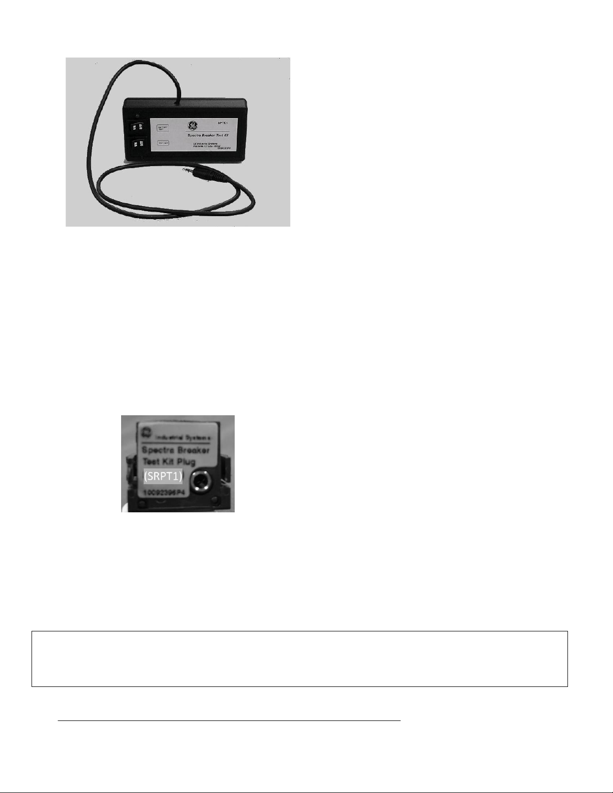
Fig 1: Spectra Breaker Test Kit
STEP8: Remove the phone jack from the Spectra Breaker
rating plug.
STEP9: Remove the Spectra Test Rating Plug using the
procedure of step 3.
STEP10: Install the proper rating plug using the
Instruction of Step 4.
Fig 2: Test Rating Plug
 Loading...