

Page 1
Installation Guide
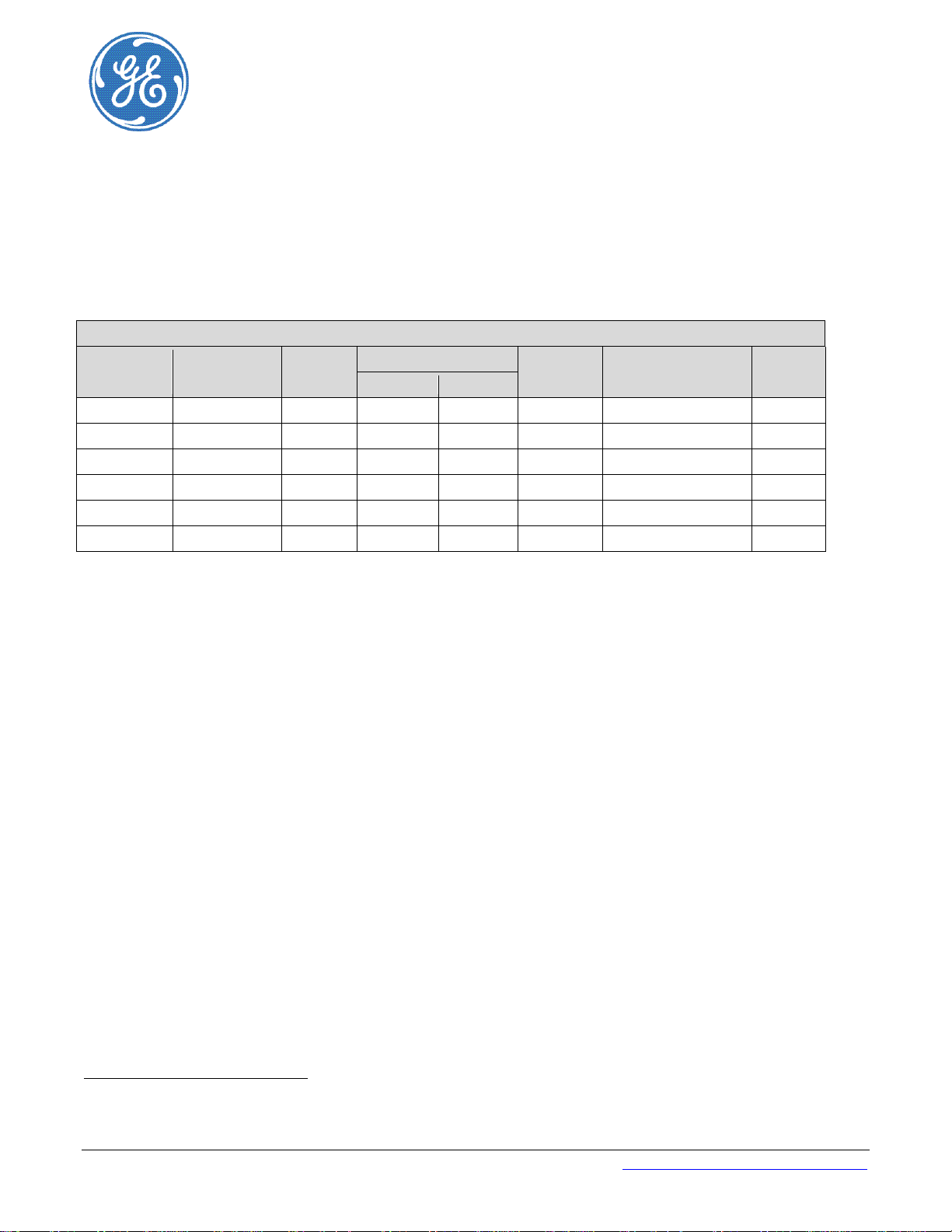
Micro-BDCBB Configurations
Buses
Battery
Return
19”
14
-
12 or 2
12 or 2
-
108992070
3
19”
14 2 2 1 VIM1
CC109145455
4
19”
14 2 1 1 VIM1
CC109145447
8
23”
22
-
12 or 2 1 -
108991056
1
23”
22 2 2
12 or 2
VIM1
CC109145463
2
23”
22 2 1
12 or 2
VIM1
CC109145430
6
Micro-BDCBB DC Battery Distribution Circuit Breaker Bay
ED83368-30
600 A, −48V / +24V, 19” or 23”
Mounting
Notes:
1. Group 1 – Field conversion to +24V and Dual buses is not supported.
2. Group 3 – Field conversion to +24V is not supported.
Fuse/Breaker
Positions
Shunts1
Meter Ordering Code Group
1 Shunts, when provided, are two 600A shunts, one on each side - A Bus (left) and B bus (right).
2 Factory Configuration – Convert to 2-bus by removing the installed bridging bus bar.
Service and Assistance - call +1 877 546 3243 or +1 972 244 9288 http://www.ge.com/powerelectronics
© 2012 General Electric Company. All rights reserved.
850027449 Issue 1 December 2012 1
The VIM1 meter sums the two shunts for one battery bus configurations.
Page 2
Micro-BDCBB ED83368-30
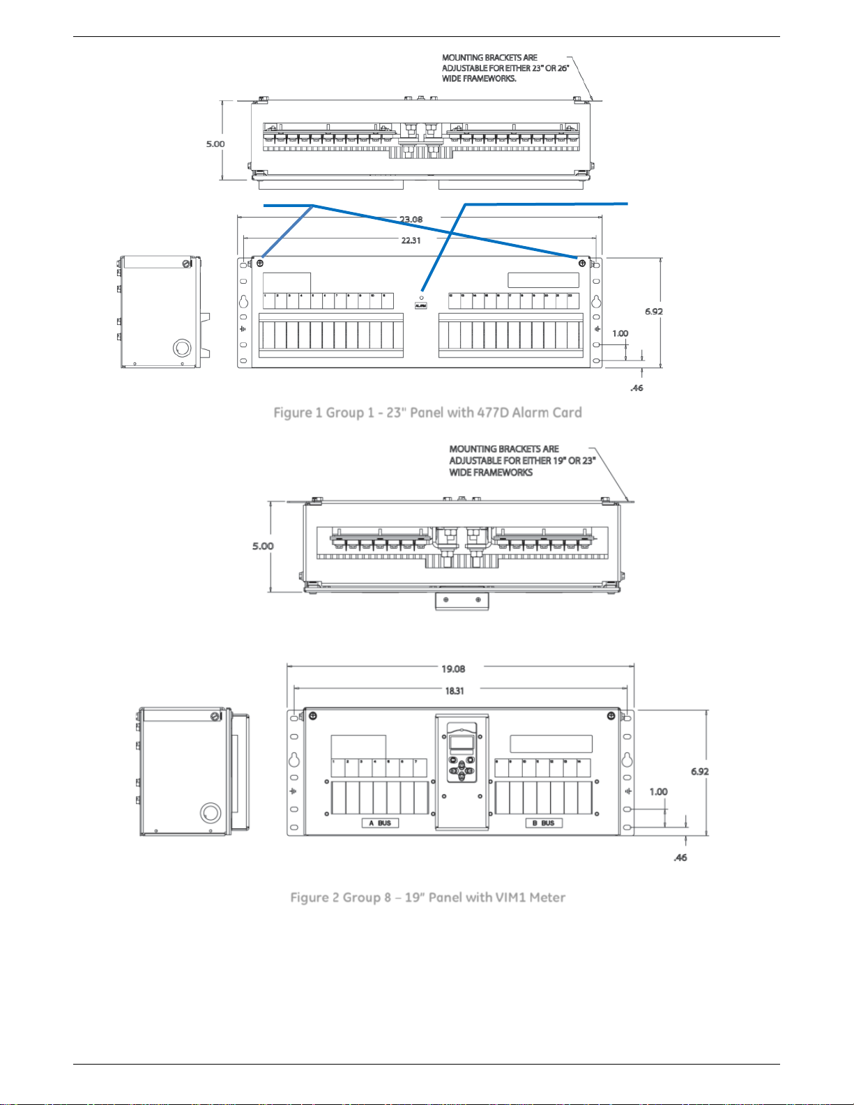
Front Panel Screws
Alarm LED
Figure 1 Group 1 - 23" Panel with 477D Alarm Card
850027449 Issue 1 DRAFT December 2012 2
Figure 2 Group 8 – 19” Panel with VIM1 Meter
Page 3
Micro-BDCBB ED83368-30
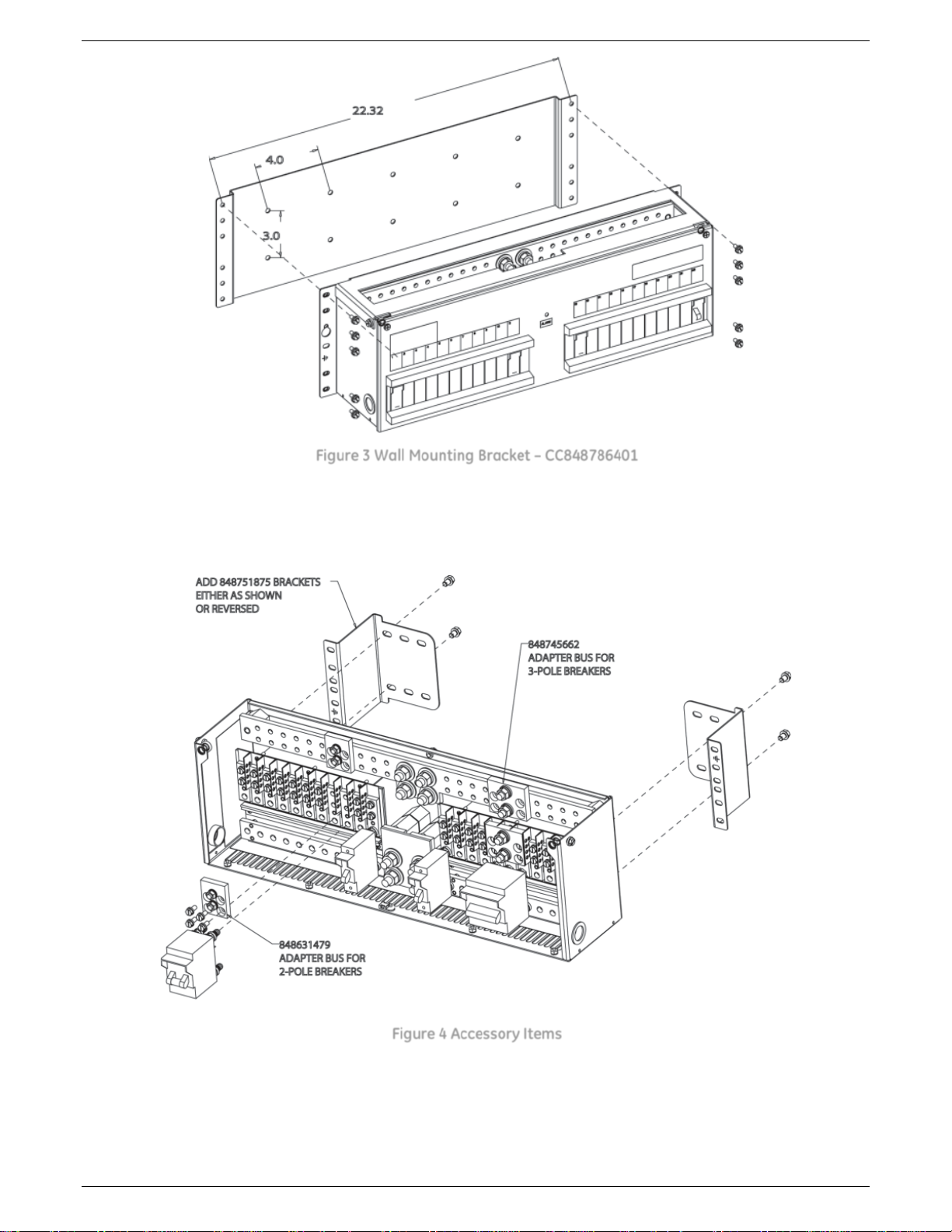
Figure 3 Wall Mounting Bracket – CC848786401
Figure 4 Accessory Items
850027449 Issue 1 DRAFT December 2012 3
Page 4

Micro-BDCBB ED83368-30
Installation Notes
1. Follow all Installation Notes. Read before installing, maintaining, or repairing the equipment.
2. Follow all site specific installation notes and instructions.
3. Mount to grounded frame using 12-24 screws provided.
Grounding for the equipment is through this connection to the frame.
Make sure frame is properly grounded.
4. Do not install this equipment over combustible surfaces.
5. Follow NEC, and local and national codes and rules.
6. Use a personal ESD strap when accessing or removing electronic components.
7. Use only protectors and holders specified in the equipment Ordering Guide.
8. 90A and 100A 1-pole breakers require an adjoining position be left unoccupied for thermal reasons.
9. Size protectors (fuses or circuit breakers) as required by the National Electric Code (NEC) and/or local codes.
Refer to the equipment ratings to assure current does not exceed:
Continuous Load (List 1) - 64% of protector rating
Maximum Load (List 2 - typically end of discharge) - 80% of protector rating.
10. Field-wired Conductors - Follow all National Electric Code (NEC) and local rules and regulations when making
field connections.
• Size field-wired conductors based on listed recommendations, National Electric Code (NEC) and/or local
codes based on 70°C ampacity.
• Insulation rating: 90°C minimum; 105°C (minimum) if internal to enclosed equipment cabinets.
11. Bonding Network - Suitable for installation as part of either
• Common Bonding Network (CBN)
• Isolated Bonding Network (IBN)
12. Facilities - Suitable for installation in
• Network Telecommunication Facilities
• Locations where the NEC applies
13. DC Return - Isolated DC Return (DC-I) or Common DC Return (DC-C)
14. Intra-building ports - Equipment and subassembly ports are suitable for connection to intra-building or
unexposed wiring or cabling. The equipment and subassembly ports can be connected to shielded intrabuilding cabling grounded at both ends.
850027449 Issue 1 DRAFT December 2012 4
Page 5

Micro-BDCBB ED83368-30
J2 & J3 - Alarm Out
Close on Alarm
Open on Alarm
Convert from -48V to +24V
Notes: 1. Not applicable to panels with VIM1 meter which automatically work with -48V and +24V.
2. Not Applicable to Panels with 477D alarm card.
Panels with VIM1 meter work with either +24V or -48V automatically.
Panels with 477D alarm card work only with -48V.
Convert Battery and Return from 1 bus to 2 buses – Group 3 only
Notes: 1. Not applicable to panels with VIM1 meter which must be factory configured for single or dual bus.
2. Not applicable to Group 1which is single bus only.
Battery and return buses may be converted in configurations bridging bus bars.
1. Remove nuts and washers securing bridging Bus Bar.
2. Remove bridging Bus Bar.
3. Replace nuts and washers.
4. Torque to 120 in-lb
Battery Bridging Bus Bar Return Bridging Bus Bar
Figure 5 Bridging Bus Bars
Alarm Card 477 Alarm Jumper
Not applicable to panels with VIM1 meter.
Position the jumper on HDR1 for Open on Alarm or Close on Alarm.
J1
Figure 6 Alarm Card
Alarm Jumper - HDR1
850027449 Issue 1 DRAFT December 2012 5
Page 6

Micro-BDCBB ED83368-30
Load A
Battery Return Connections
Load B
Load A
Load B
A Breakers
B Breakers
Load Connections
Battery Connections - 3/8” on 1” centers – torque 16 ft-lb
Load Connections
Return Connections
Battery Connection
Breaker Load Connections - 1/4” on 5/8” centers – torque 55 in-lb
Return Connections
Battery Connection
2-Load configuration shown
Figure 7 DC Connections
Battery Connections – Loads - Figure 7
For single load configurations, A and B sections are bridged: Battery, Battery Return, Breaker Loads, and Load
Returns.
1. Connect battery feeds and returns.
2. Connect Breaker loads and returns.
Breakers and Fuse Holders
1. Open Breaker Access Covers by loosening front panel screws.
2. Install protectors and protector holders
3. Close Breaker Access Covers and tighten Breaker Access Screws.
4. Install fuses into fuse holders.
5. Install multi-pole bus kits included with each protector and protector holder occupying 2 or 3 positions.
Load Connections - Figure 7
1. Connect breaker load wires to Breaker Load Connections.
2. Connect breaker load return wires to the Return Bus.
850027449 Issue 1 DRAFT December 2012 6
Page 7

Micro-BDCBB ED83368-30
Alarm Cable Pinouts and Description
VIM1 Meter
Alarm Card - 477
Pin
Form-C
Alarm3
Wire Color
Pin
Alarm
Wire Color
7
Fuse NO
Blue
J2-1
Fuse
Brown
1
Fuse NC
White/Blue
J2-2
Fuse C
Yellow
2
Fuse C4
Slate
J3-1
Fuse
Brown
10
OVL NO
White/Slate
J3-2
Fuse C
Yellow
4
OVL NC
Orange
5
OVL C
White/Orange
12
PL NO
Yellow
6
PL NC
White/Yellow
11
PL C
White
Alarm Wiring
20 AWG recommended.
1. Butt-splice office alarm wires to the provided alarm cable.
2. Connect the alarm cable connector to the VIM1 meter or alarm card.
3
4
850027449 Issue 1 DRAFT December 2012 7
NO signals Open on Alarm. NC signals Close on Alarm.
C signals, such as “Fuse C” are common or return signals for the similarly named signals, such as “Fuse NO”.
Page 8

Micro-BDCBB ED83368-30
Previous Menu
Display
Display Menus
Arrows Keys
VIM1 Meter
The VIM1 can be configured to display the voltage, current, and panel identifier of each monitored load bus.
Notes specific to application in this equipment 5067:
1. Lamp Test does not activate 5067 Alarm LED - Figure 1.
Alarm Indication
When an alarm occurs, LCD backlight on the display changes color from green (normal) to red (alarm active). The
front panel text also changes from “No Alarms” to “Alarms”
Navigation Keys
Left and Right Keys are used for menu navigation. Up and Down keys are used to change the parameter values of
the meter. They also allow screen contrast adjustment at:
Menu►System Parameters►Display Contrast
Save Changes
Refresh
Navigate Menus
Adjust Values in Con
Figure 8 VIM1 Meter
Alarm and Monitoring
Visual, Audible and Remote Alarms
The VIM1 monitor includes an audible alarm with a user configurable on/off feature. There is a form-C relay for
each of the three alarms for remote monitoring.
All alarms are active when the VIM1 is unpowered. Alarms are asserted when their relay coils are not powered.
Power Loss/Under Voltage
Generates an alarm when power is lost to a load bus or when a user configurable low voltage threshold is reached.
Overload
Generates an alarm when a user configurable current threshold is reached. A configurable time delay may also be
set to avoid nuisance alarms due to bus transients.
Breaker/Fuse
Generates an alarm when either a circuit breaker trips or a fuse blows.
Network Connectivity
There are two RJ45 type connectors on the board for future use.
850027449 Issue 1 DRAFT December 2012 8
Page 9
Micro-BDCBB ED83368-30
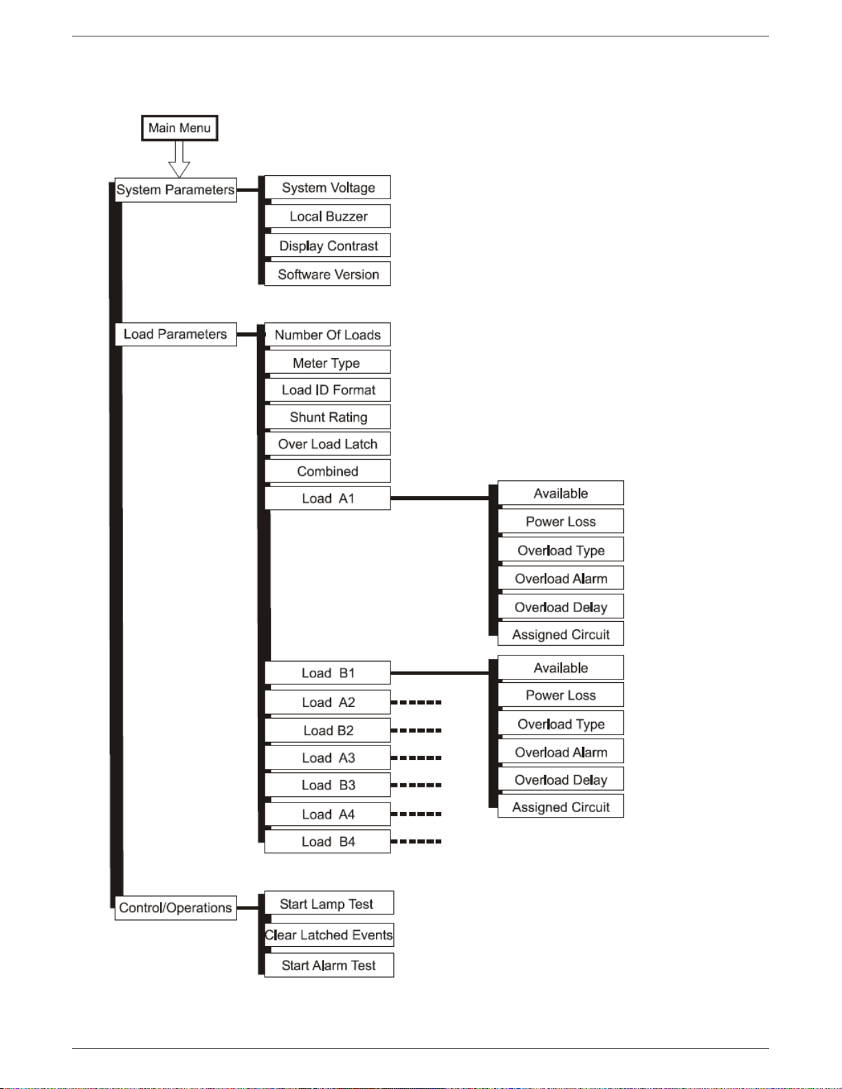
Menu Map
The VIM1 front panel is structured such there are three main menu items: System Parameters, Load Parameters,
and Control/Operations. Each key menu item has sub items as shown in the menu map below.
850027449 Issue 1 DRAFT December 2012 9
Page 10

Micro-BDCBB ED83368-30
System Parameters
Description
48V.
Disabled.
from 0-100% in 1% increments. Factory default is 50%.
Displays the version of the application code running in the meter in the format
(vX.Y). Version 1.5 is the latest as of this printing.
Load Parameters
Description
Used to identify the number of individual loads/buses in the distribution. Value
configurable from 1-8. Factory default is 6.
Configures meter to display individual monitored bus voltages (voltage), voltages
(volt_curr).
Configures display format used in referencing individual DC loads/buses.
1, 2, 3, 4 … format. Factor Default is to use the A1 format.
Used to indicate where the first load in the distribution is located. Allowable
right). Every monitored shunt is considered a load. Factory default is “top-left”.
Used to define the current rating of the shunt in the load bus. All shunts in the
4000A. The factory default is 800A.
A single configuration for all panels/buses that allows a temporary Over Load
event to be latched. Factory default is “Disabled”.
Displays the load value as one combined sum by adding up all shunts in the
system and presenting it as values for a single load. Factory default is disabled.
Indicates if the load is available or in use. Allowable configurations are “installed”
“installed”.
The Power Loss (PL) alarm is triggered upon loss of the primary DC or when the
are 40.00V and 20.00V, respectively.
The Power Overload Type defines whether the smart meter is to treat the
(OVL) alarm. Factor default is “Single Bus” configuration”.
The Load Overload (OVL) alarm event is triggered when any measured panel
can be configured from 1-4000A. Factory default is 800A.
Programming the Meter
VIM1 parameters like shunt size and number of load buses are preconfigured when it is factory installed in a
BDFB/BDCBB or Micro-BDFB. Only customer specific preferences need to be adjusted in the field. As a
replacement or mete upgrade, the factory default settings may need to be adjusted for the application. Listed
below are the configurable parameters and their associated factory defaults available through the front panel.
Following the table are the typical items that need to be configured or verified in a retrofit or replacement
application.
System Voltage
Local Buzzer
Display Contrast
Software Version
Number Of Loads
Meter Type
Load ID Format
First Load (location)
Shunt Rating
Used to identify system voltage. Selectable between 24V and 48V. Factory default is
Allows the integrated audible alarm to be Enabled or Disabled. Factory default is
Allows the display contrast to be adjusted for the local ambient lighting. Adjustable
and currents (volt_curr), or only currents (current). This configuration is defined by
the internal wiring of the distribution. Factory default is Voltage and Current
Allowable formats: A1, A, and 1. “A1” identifies loads using an A1, B1; A2, B2; …
format. “A” identifies loads using an A, B, C, D ... format. “1” identifies loads using a
configurations are: top-left, top-right, btm-left (bottom-left), btm-right (bottom-
load must be of the same size. A 50mV shunt is assumed. Allowable range is 1-
Overload Latch
Combined Load
Load Available
(A1-A4;B1- B4)
Load Power Loss
Load Overload
Type
Load Overload
850027449 Issue 1 DRAFT December 2012 10
and “not installed”. “Installed” loads imply that the load is in use. “Not Installed”
loads imply that the load may be present, but it is not in use. Information
obtained from the load should not be relevant. Factor default is set to be
individual’s panels’ DC input has reached the configured low voltage threshold.
This Power Loss voltage threshold is configurable between 40.00-60.00V for 48V
systems and 20.00-30.00V for 24V systems. Factory defaults for these thresholds
Overload alarm event for a “Single Bus” or for an “Redundant Bus” configuration.
The “Single Bus” configuration is based on straight Overload threshold being
exceeded. The “Redundant Bus” configuration causes the VIM1 to sum the two
respective left and right load shunt measurements and compare it to the
individual overload thresholds configured for the each of the respective panels in
the pairing. The lowest Overload value threshold configured for the Redundant
loads shall take priority and be used in the comparison. Once the “Redundant
Bus” measurement exceeds this threshold, the controller asserts the Over Load
currents exceed their respective configured thresholds. These OVL thresholds
Page 11

Micro-BDCBB ED83368-30
Delay
An Overload Delay can be set to prevent nuisance alarms. This delay is
The VIM1 has eight individual load circuits with each circuit having voltage and
rearranged details of the circuit connections can be seen in T83150-30.
Parameters
Cycles the illumination of the front panel LED and Backlight through Red, Amber,
and Green
Events
Clears a latched Overload Alarm event. Note the Overload Latched Event must be
Asserts Form-C alarms available at connector J3 in a fixed sequence: Fuse Alarm
wiring.
Bullet Style Load Circuit Breakers
Ordering Code
Amperage
CB Positions (Poles)
Min. Wire Gage
407998137 3 1
10
407998145 5 1
10
407998152
10
1
10
407998160
15
1
10
407998178
16
1
10
407998186
20
1
10
407998194
25
1
10
407998202
30
1
10
408213486
40
1
8
407998210
45
1
8
407998228
50
1
6
407998236
60
1
6
407998244
70
1
2
407998251
80
1
2
407998269
90
1
2
407998277
100
1
2
CC848808551
100
2
2
408185353
125
2
2
408185346
150 2 1/0
408564941
200 3 2/0
408573975
225 3 4/0
408535752
250 3 4/0
Multi-Pole Adapter Bus Kits – 1 per multi-pole breaker
Ordering Code
CB Positions (Poles)
Hardware Included
850021775 2 5/16” on 1” centers
850021955 3 5/16” on 1” centers
Load Overload
Assigned Circuits
Control and
Operations
Start Lamp Test
Clear Latched
Start Alarm Test
configurable between 0-300 seconds. Factory default is 0 seconds.
shunt measurement capability. These circuits are pre-wired with fixed positions
in the Lineage BDFB/BDCBBs. If circuit wiring from the VIM is redressed in the
field this feature can be used to assign the appropriate circuit to the new load
location.
Note: in the 6-load H569-445 circuits 1-6 are attached in a descending order
viewing from the front of the system in a top left to right numbering scheme. The
VIM1 will automatically assign the right circuit if only the first “Load Location” is
utilized and the internal wiring is not touched. Note: if wiring has been
Description
enabled to have a latched alarm.
(FA), Power Loss (PL), and Overload (OVL). Alarm asserted is displayed on the front
panel. Feature can be used to test the site’s remote monitoring systems and
850027449 Issue 1 DRAFT December 2012 11
Page 12

Micro-BDCBB ED83368-30
Bullet Style Fuse Holder and TPS/TLS Fuses Style Fuse Holder and TPS/TLS Fuses
Ordering Code
Amperage
406700567
3
406700583
5
406700591
6
406700609
10
406700617
15
406700625
20
406700633
25
406700641
30
406700658
40
406700674
50
406700682
60
406700690
70
CC408618020
80
CC408618037
90
CC408618045
100
CC408618061*
125
402328926
0.18 Alarm Fuse
408548944
Bullet Fuse Holder, TFD-101-011-09 (Alarms on Blown Fuse or Fuse Head Removal)
CC408617410
Bullet Fuse Holder, TFD-101-011-10 (Alarms on Blown Fuse Only)
Bullet Style GMT Fuse Holder and GMT Fuses
405006222
0.25A
406976894
0.5A
405673146
1.33A
405181983
2A
406976985
3A
406159061
5A
405725433
7.5A
406159236
10A
406473959
12A
CC109103157
6-pos GMT Bullet Fuse Holder, requires 2 positions
408515823
Fuse Puller
* Maximum of 3 125A fuses per side. A space must be left between each fuse.
850027449 Issue 1 DRAFT December 2012 12
 Loading...