

Page 1
g
MicroVersaTrip Plus™ and
MicroVersaTrip PM™ Trip Units
for Type AKR Low-Voltage Power Circuit Breakers
Power Break
Power Break
R-Frame Molded-Case Circuit Breakers
Low-Voltage Power Circuit Breaker Conversion Kits
User’s Guide
GEH–6273E
® Insulated-Case Circuit Breakers
® II Insulated-Case Circuit Breakers
Page 2

Page 3

WARNINGS
g
CAUTIONS
NOTES
GEH–6273E
WARNINGS, CAUTIONS, AND NOTES
AS USED IN THIS PUBLICATION
Warning notices are used in this publication to emphasize that hazardous voltages, currents, or other conditions that could cause personal injury exist in this equipment or may
be associated with its use.
Warning notices are also used for situations in which inattention or lack of equipment
knowledge could cause either personal injury or damage to equipment.
Caution notices are used for situations in which equipment might be damaged if care is
not taken.
Notes call attention to information that is especially significant to understanding and
operating the equipment.
This document is based on information available at the time of its publication. While
efforts have been made to ensure accuracy, the information contained herein does not
cover all details or variations in hardware and software, nor does it provide for every possible contingency in connection with installation, operation, and maintenance. Features
may be described herein that are not present in all hardware and software systems. GE
Electrical Distribution & Control assumes no obligation of notice to holders of this document with respect to changes subsequently made.
GE Electrical Distribution & Control makes no representation or warranty, expressed,
implied, or statutory, with respect to, and assumes no responsibility for the accuracy,
completeness, sufficiency, or usefulness of the information contained herein. No warrantees of merchantability or fitness for purpose shall apply.
The following are trademarks of GE Company:
MicroVersaTrip Plus™, MicroVersaTrip PM™, Power Break®, Spectra RMS™, Epic™,
POWER LEADER™
©Copyright 1996 GE Company
All Ri
hts Reserved
i
Page 4

MicroVersaTrip Plus™ and MicroVersaTrip PM™ Trip Units
Table of Contents
Chapter 1. Introduction
1-1 Read This First ............................................................................................................1
1-2 Product Structure ........................................................................................................1
1-3 Trip Unit Functions.....................................................................................................3
1-4 Trip Unit Catalog Numbers.........................................................................................3
1-5 Rating Plugs.................................................................................................................5
1-6 Equipment Interfaces.................................................................................................. 6
MicroVersaTrip Plus Trip Units............................................................................6
Neutral Current Sensors........................................................................................6
MicroVersaTrip PM Trip Units.............................................................................6
POWER LEADER Communication Network........................................................6
Voltage Inputs.......................................................................................................6
Power Requirements .............................................................................................7
1-7 Trip Unit Information.................................................................................................7
Trip Unit Label Information ................................................................................7
Function Keys........................................................................................................7
Battery Function....................................................................................................8
Liquid Crystal Display ...........................................................................................9
1-8 MicroVersaTrip Plus and MicroVersaTrip PM Accuracies.......................................... 9
Chapter 2. Setup Mode
2-1 Overview ....................................................................................................................10
2-2 Operating Modes....................................................................................................... 10
2-3 Setup Mode Operation.............................................................................................. 10
Long-Time Pickup .............................................................................................. 16
Long-Time Delay................................................................................................. 16
Short-Time Pickup .............................................................................................. 16
Short-Time Delay ................................................................................................ 17
Instantaneous Pickup.......................................................................................... 18
High-Range Instantaneous Overcurrent Protection ........................................... 18
Ground-Fault Pickup........................................................................................... 18
Ground-Fault Delay............................................................................................. 19
Voltage-Unbalance Relay Pickup ........................................................................ 19
Voltage-Unbalance Relay Delay ..........................................................................20
Current-Unbalance Relay Pickup........................................................................ 20
Current-Unbalance Relay Delay.......................................................................... 20
Undervoltage Relay Pickup................................................................................. 20
Undervoltage Relay Zero-Volt Trip Enable......................................................... 20
Undervoltage Relay Delay................................................................................... 21
Overvoltage Relay Pickup.................................................................................... 21
Overvoltage Relay Delay...................................................................................... 21
Power-Reversal Relay Pickup............................................................................... 21
ii
Page 5

MicroVersaTrip Plus™ and MicroVersaTrip PM™ Trip Units
Power Direction Setup......................................................................................... 21
Power-Reversal Relay Delay................................................................................. 21
Rating Plug Current Setting................................................................................ 22
Potential Transformer Primary Voltage.............................................................. 22
Potential Transformer Connection..................................................................... 22
Power Demand Intervals..................................................................................... 23
Communication Address .................................................................................... 23
Accessory Configuration Setup (RMS9D Series Trip Units Only) ...................... 23
Chapter 3. Metering Mode
3-1 Overview ....................................................................................................................25
3-2 Metering Mode Operation ........................................................................................25
Current................................................................................................................ 27
Voltage ................................................................................................................ 27
Energy................................................................................................................. 27
Total Real Power................................................................................................. 27
Total Aggregate Power........................................................................................ 28
Power Demand.................................................................................................... 28
Peak Power Demand ........................................................................................... 28
Frequency............................................................................................................ 28
Table of Contents
Chapter 4. Status Mode
4-1 Overview ....................................................................................................................29
Trip Information ................................................................................................ 29
Trip Operations Counters................................................................................... 29
4-2 Status Mode Operation.............................................................................................. 29
Normal Status Display ......................................................................................... 29
Long-Time Overcurrent Pickup Display ............................................................. 29
Trip Target and Fault Displays ........................................................................... 30
Long-Time Overcurrent Fault Display ................................................................ 30
Short-Time Overcurrent Fault Display................................................................ 30
Instantaneous Fault Display................................................................................ 30
Ground-Fault Display.......................................................................................... 31
Protective-Relay Fault Display ............................................................................. 31
Shunt Trip and Undervoltage Release Trip Displays (RMS9D Series Trip
Units Only) ................................................................................................... 31
Clearing the Trip Information............................................................................ 31
Trip Operations Counter Display ....................................................................... 31
Clearing the Trip Operations Counters.............................................................. 32
iii
Page 6

MicroVersaTrip Plus™ and MicroVersaTrip PM™ Trip Units
Table of Contents
Chapter 5. Maintenance and Trouble-Shooting
5-1 Trip Unit Removal and Replacement ....................................................................... 33
Power Break Insulated-Case Circuit Breakers .....................................................33
Power Break II Insulated-Case Circuit Breakers.................................................. 33
Type AKR Low-Voltage Power Circuit Breakers.................................................. 33
5-2 Rating Plug Removal and Replacement.................................................................... 34
5-3 Trouble-Shooting Guide............................................................................................ 34
Appendices
Catalog Numbers for RMS9C Units in AK/AKR Circuit Breakers .................................. 36
Catalog Numbers for RMS9C Units in Power Break® Circuit Breakers.......................... 37
Catalog Numbers for RMS9D Units in Power Break® II Circuit Breakers...................... 38
Trip Unit Battery Suppliers............................................................................................. 39
iv
Page 7

MicroVersaTrip Plus™ and MicroVersaTrip PM™ Trip Units
List of Figures
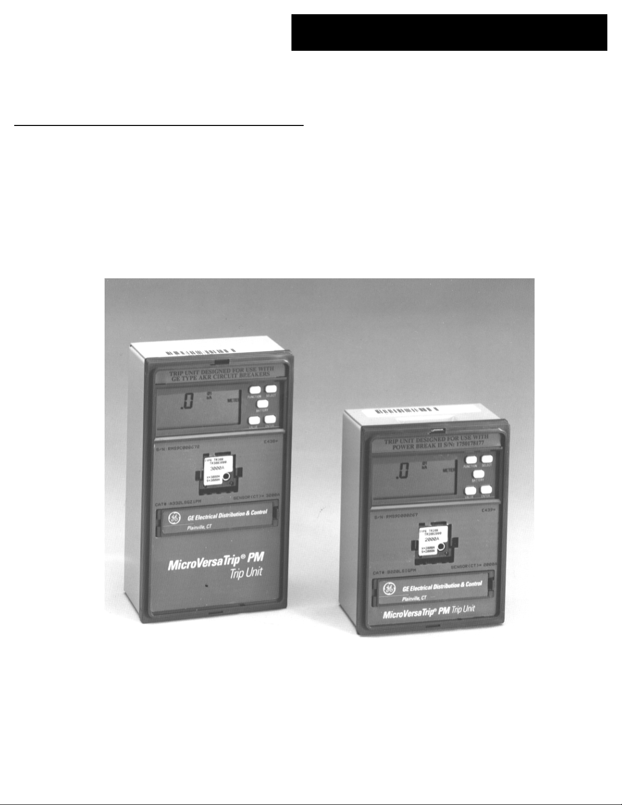
1. Front view of MicroVersaTrip PM Trip Unit (series RMS9C).................................................1
2. Front view of MicroVersaTrip PM Trip Unit (series RMS9D). ...............................................1
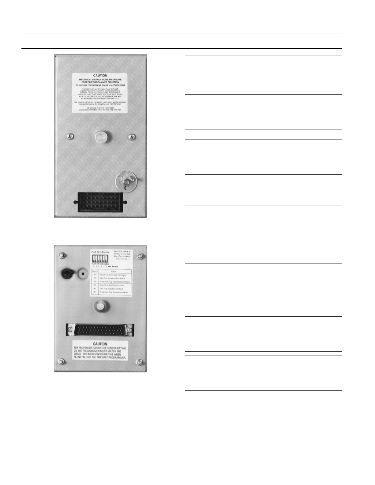
3. Rear view of MicroVersaTrip PM Trip Unit (series RMS9C)................................................. 2
4. Rear view of MicroVersaTrip PM Trip Unit (series RMS9D)..................................................2
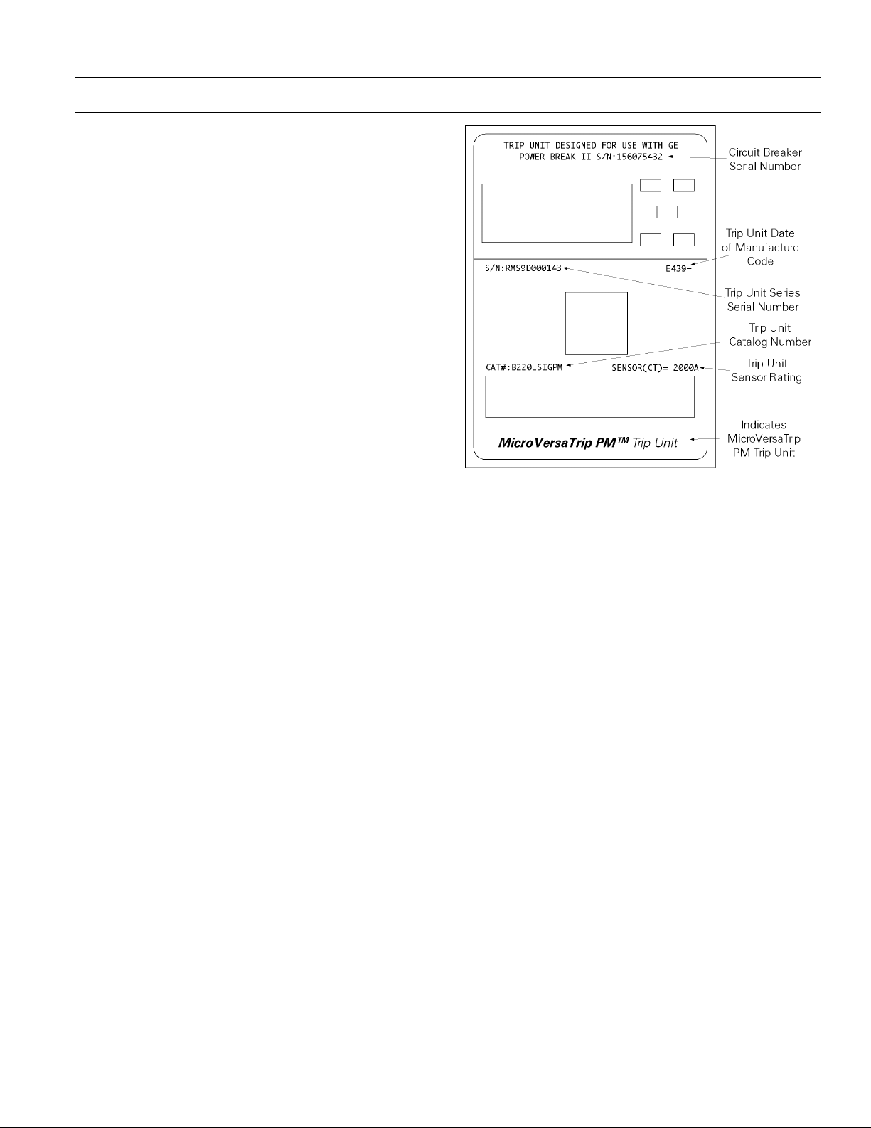
5. Labels on front of Trip Unit....................................................................................................7
6. Function key placement on face of Trip Unit......................................................................... 8
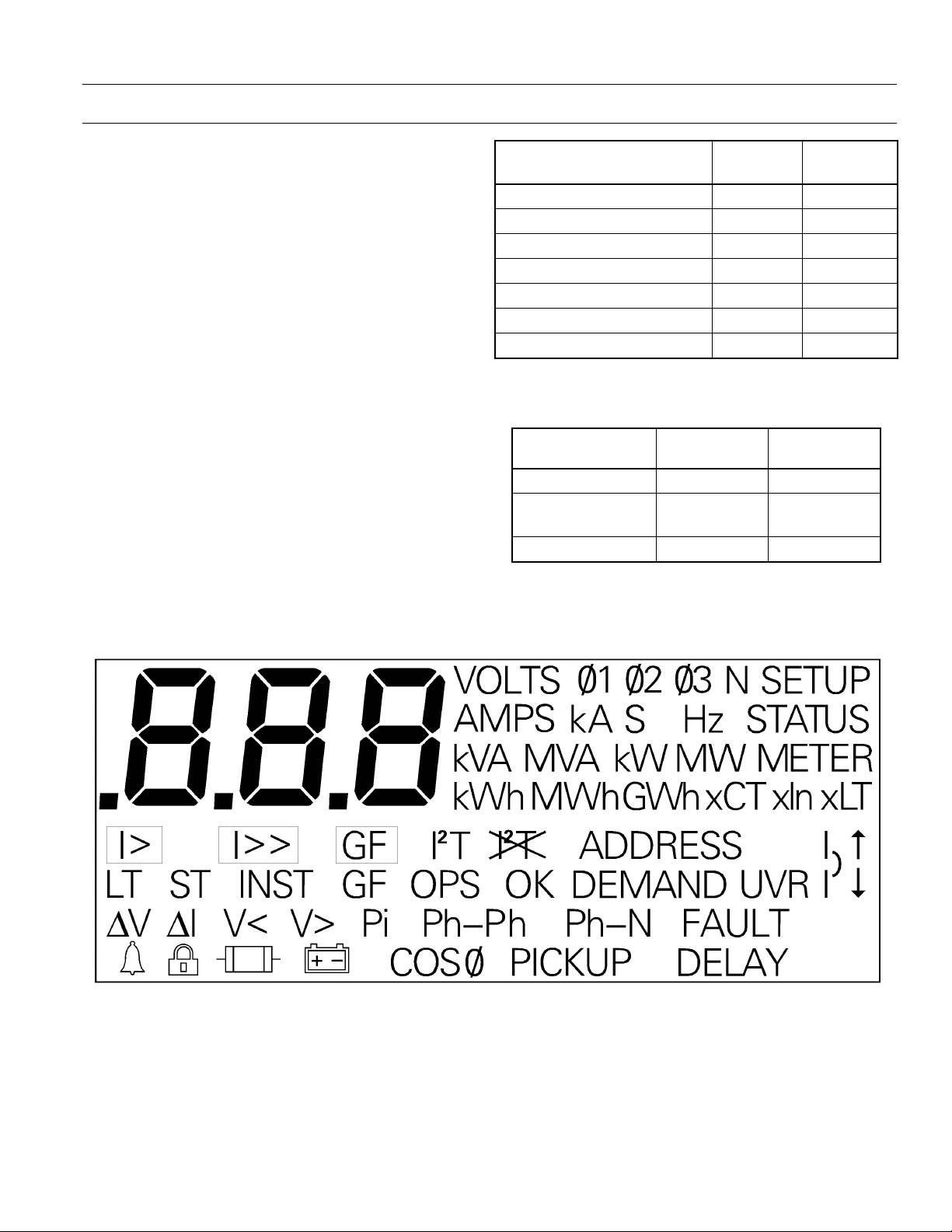
7. Liquid crystal display segments...............................................................................................9
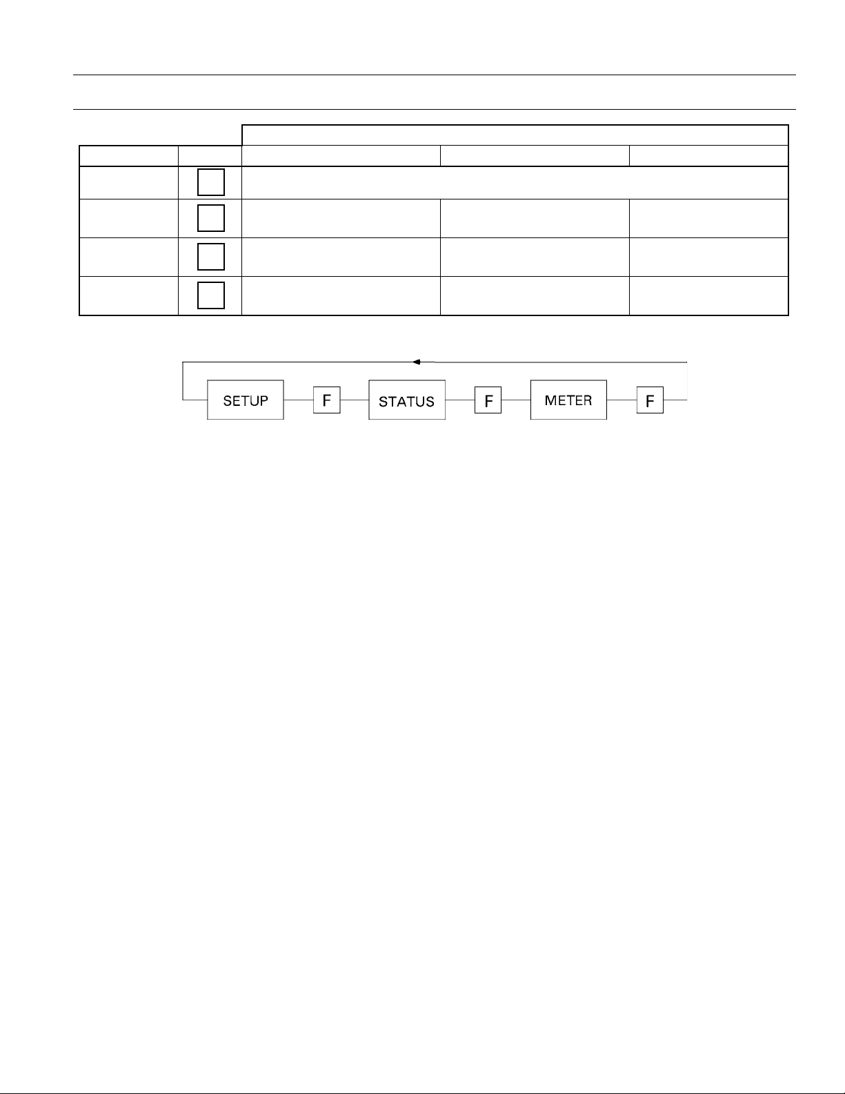
8. Operation of FUNCTION key, showing progression among Trip Unit operating modes.... 11
9. Trip Unit setup mode programming function flow.............................................................. 12
10. Trip Unit display for long-time pickup................................................................................. 16
11. Time-current curve illustrating long-time pickup................................................................ 16
12. Trip Unit display for long-time delay.................................................................................... 16
13. Time-current curve illustrating long-time delay....................................................................16
14. Trip Unit display for short-time pickup coupled with long-time pickup. ............................. 17
15. Time-current curve illustrating short-time pickup................................................................ 17
16. Trip Unit display for short-time delay................................................................................... 17
17. Time-current curve for short-time delay with
18. Time-current curve for short-time delay with
19. Trip Unit display for instantaneous pickup.......................................................................... 18
20. Instantaneous overcurrent protection set point.................................................................... 18
21. Trip Unit display for ground-fault pickup. ........................................................................... 18
22. Time-current curve for ground-fault pickup........................................................................ 19
23. Trip Unit display for ground-fault delay, showing
24. Time-current curve for ground-fault delay with
25. Time-current curve for ground-fault delay with
26. Trip Unit display for voltage-unbalance relay pickup........................................................... 20
27. Trip Unit display for voltage-unbalance relay delay.............................................................. 20
28. Trip Unit display for current-unbalance relay pickup. ......................................................... 20
29. Trip Unit display for current-unbalance relay delay............................................................. 20
30. Trip Unit display for undervoltage relay pickup................................................................... 20
31. Trip Unit display for undervoltage relay zero-volt trip disabled. .......................................... 20
32. Trip Unit display for undervoltage relay zero-volt trip enabled............................................ 21
33. Trip Unit display for undervoltage relay delay. .................................................................... 21
34. Trip Unit display for overvoltage relay pickup...................................................................... 21
35. Trip Unit display for overvoltage relay delay........................................................................ 21
36. Trip Unit display for power-reversal relay pickup................................................................. 21
37. Trip Unit display for power direction setup, showing line to load........................................ 21
38. Trip Unit display for power-reversal relay delay.................................................................... 22
39. Trip Unit display for rating plug current set point............................................................... 22
40. Trip Unit display for potential transformer primary voltage set point. ................................ 22
I2T OUT. ......................................................... 17
I2T IN.............................................................. 17
I2T out. ................................................... 19
I2T OUT. ..................................................... 19
I2T IN.......................................................... 19
v
Page 8

MicroVersaTrip Plus™ and MicroVersaTrip PM™ Trip Units
List of Figures
41. Trip Unit display for potential transformer connection choice............................................ 23
42. Trip Unit display for power demand interval....................................................................... 23
43. Trip Unit display for setting communication address.......................................................... 23
44. Logic diagram for accessory configurations.......................................................................... 23
45. Accessory configuration switch on rear of Trip Unit, showing factory settings. ................... 24
46. Setting the accessory configuration switches.........................................................................24
47. Trip Unit metering mode function flow............................................................................... 25
48. Trip Unit display for current metering................................................................................. 27
49. Trip Unit display for line-to-neutral voltages........................................................................ 27
50. Trip Unit display for line-to-line voltages.............................................................................. 27
51. Trip Unit display for aggregate energy................................................................................. 27
52. Trip Unit display for aggregate real power........................................................................... 27
53. Trip Unit display for aggregate apparent power...................................................................28
54. Trip Unit display for power demand.................................................................................... 28
55. Trip Unit display for frequency............................................................................................. 28
56. Trip Unit display for normal status....................................................................................... 29
57. Trip Unit status display for long-time overcurrent pickup.................................................... 30
58. Typical fault display following a breaker trip........................................................................ 30
59. Trip Unit Status display for long-time overcurrent trip. ....................................................... 30
60. Trip Unit status display for short-time overcurrent trip........................................................ 30
61. Trip Unit status display for instantaneous overcurrent trip.................................................. 30
62. Trip Unit status display for ground-fault trip....................................................................... 31
63. Trip Unit status display for protective-relay trip. .................................................................. 31
64. Trip Unit status display for Undervoltage Release trip......................................................... 31
65. Trip Unit status display for long-time overcurrent trip counter............................................ 32
66. Removing the interchangeable rating plug.......................................................................... 34
vi
Page 9

MicroVersaTrip Plus™ and MicroVersaTrip PM™ Trip Units
List of Tables
1. Breaker type referred to by first character of Trip Unit catalog number................................3
2. Breaker frame size maximum CT referred to by second character of Trip Unit catalog
number....................................................................................................................................4
3. Installed breaker CT size referred to by third and fourth characters of Trip Unit catalog
number....................................................................................................................................4
4. Trip Unit catalog number suffixes for optional functions...................................................... 4
5. MicroVersaTrip PM Trip Unit suffixes for communication, metering, and relaying.............4
6. Rating plug catalog numbers.................................................................................................. 5
7. Protective relay and metering accuracies and resolutions. .....................................................9
8. Trip-time curves for breaker types covered in this guide. .......................................................9
9. Abbreviations used in setup procedure descriptions............................................................. 10
10. Actions of function keys in Trip Unit operating modes........................................................11
11. Lower-limit delays for long-time delay bands........................................................................ 16
12. Lower-limit delays for
13. Instantaneous pickup settings for various frame sizes with and without the short-time
function................................................................................................................................. 18
14. Ground-fault pickup settings, as a function of sensor rating................................................. 18
15. Lower-limit delays for ground-fault delay bands................................................................... 19
16. Trip Unit rating plug options............................................................................................... 22
17. Accessory configuration switch settings, including factory defaults......................................24
18. Trip Unit display targets for protective relays....................................................................... 31
I2T OUT short-time delay bands.......................................................... 17
vii
Page 10

Page 11

MicroVersaTrip Plus™ and MicroVersaTrip PM™ Trip Units
1-1 Read This First
The MicroVersaTrip Plus™ and MicroVersaTrip
PM™ Trip Units described in this publication are
used on Power Break® and Power Break® II
insulated-case circuit breakers, Type AKR low-voltage
power circuit breakers, R-Frame molded-case circuit
breakers, and low-voltage power circuit breaker
conversion kits.
Spectra RMS™ molded-case circuit breakers use
different versions of MicroVersaTrip Plus and
MicroVersaTrip PM Trip Units that are not
interchangeable with the units described here. Refer
to GEH-5934 for information on these Trip Units.
1-2 Product Structure
MicroVersaTrip Trip Units come in two different
sizes that are not interchangeable. The larger Trip
Unit (series RMS9C) is used on Power Break circuit
breakers, Type AKR circuit breakers, and conversion
kits. The smaller Trip Unit (series RMS9D) is used
only on Power Break II circuit breakers. Each of the
two sizes is available in both MicroVersaTrip Plus
and MicroVersaTrip PM configurations. The front
views of the MicroVersaTrip PM Trip Units are
shown in Figures 1 (RMS9C) and 2 (RMS9D).
Chapter 1. Introduction
Figure 1. Front view of MicroVersaTrip PM Trip Unit (series
RMS9C).
The RMS9C Trip Unit has a 36-pin rear connector,
while the RMS9D Trip Unit has a 50-pin rear connector, as shown in Figures 3 and 4. These connectors provide the Trip Units’ main connections to the
circuit breaker frame and to the equipment control
signals.
Both types of Trip Unit have recessed connectors in
the front panel to accept interchangeable current
rating plugs.
Both types of Trip Unit have a top-mounted 20-pin
connector that provides future access to the optional
Remote Display accessory. (
normally used with a Power Break II circuit breaker.)
This connector has a removable cover to protect it
when not in use.
Series RMS9D Trip Units also have a 6-position DIP
switch, not present on series RMS9C Trip Units, that
is used to configure the Power Break II integrated
accessories. This switch is located on the rear of the
unit.
Note:
this accessory is not
Figure 2. Front view of MicroVersaTrip PM Trip Unit (series
RMS9D).
1
Page 12
MicroVersaTrip Plus™ and MicroVersaTrip PM™ Trip Units
Chapter 1. Introduction
Figure 3. Rear view of MicroVersaTrip PM Trip Unit (series
RMS9C).
CCCCAAAAUUUUTTTTIIIIOOOONNNN::
must be performed with the breaker in the OPEN or
TRIPPED position. Draw-out breakers should be
racked out first.
AAAATTTTTTTTEEEENNNNTTTTIIIIOOOONNNN::
disjoncteur doit être en position ouverte ou
déclenchée. Les disjoncteurs débrochables doivent
ètre en position débrochée.
CCCCAAAAUUUUTTTTIIIIOOOONNNN::::
without its assigned Trip Unit. Installation of an
incorrect Trip Unit may result in unsafe operation of
the breaker.
AAAATTTTTTTTEEEENNNNTTTTIIIIOOOONNNN::
déclencheur. Une mauvaise installation du
déclencheur peut être dangereuse.
CCCCAAAAUUUUTTTTIIIIOOOONNNN::
breaker is carrying current reduces the breaker’s
current-carrying capacity to approximately 25% of
the current sensor rating. This may result in undesired tripping.
::
Removal of a Trip Unit from its breaker
::
Pour retirer déclencheur, le
Do not attempt to operate the breaker
::
Ne pas utiliser le disjoncteur sans son
::
Removal of the rating plug while the
Figure 4. Rear view of MicroVersaTrip PM Trip Unit (series
RMS9D).
AAAATTTTTTTTEEEENNNNTTTTIIIIOOOONNNN::
disjoncteur est sous tension, le déclencheur se régle
automatiquement à approximativement 25% du
calibre du transformateur de courant. Ceci peut
entrainer un déclenchement indésirable.
NNNNOOOOTTTTEEEE::
are undesirable for the specific application. Ensure
that settings are appropriately adjusted before energizing.
NNNNOOOOTTTTEEEE::
standards qui peuvent être inadéquates pour
certaines applications. Vérifier ces réglages avant de
mettre le disjoncteur sous tension.
::
Trip Units as received may have settings that
::
Les disjoncteurs sont livrés avec des réglages
::
Si le calibreur est retiré alors que le
2
Page 13

MicroVersaTrip Plus™ and MicroVersaTrip PM™ Trip Units
Chapter 1. Introduction
1-3 Trip Unit Functions
MicroVersaTrip Plus and MicroVersaTrip PM Trip
Units have specific standard and optional functions.
All Trip Units share a series of interchangeable
rating plugs. The standard functions for both types
of Trip Unit are as follows:
• Protection
– Long-time protection
– Instantaneous protection
• Status
– Trip target (trip type)
– Trip information (magnitude and phase)
– Trip operations counters
• Metering display
– Phase current (selectable among phases)
The optional functions available on both types of
Trip Unit are as follows:
• High-range (fixed) instantaneous overcurrent
protection
• Short-time protection, with or without I
• Ground-fault protection, with or without I
• Defeatable ground fault, with or without I
• Zone-selective interlock, with ground fault only
or with both ground fault and short time
protection
Additional optional functions available only with
MicroVersaTrip PM Trip Units are as follows:
• Available configurations
– Communication and metering
– Communication and protective relaying
– Communication, metering, and protective
relaying
• Remote communication with POWER
LEADER™ communications network
(commnet)
• Metering functions
– Voltage (V)
– Energy (kWh/MWh/GWh)
– Total real power (kW/MW)
– Total apparent power (kVA/MVA)
– Demand power (kW/MW)
– Peak demand power (kW/MW)
2
T
2
T
2
T
– Frequency (Hz)
• Protective relaying
– Undervoltage
– Overvoltage
– Voltage unbalance
– Current unbalance
– Power reversal
NNNNOOOOTTTTEEEE::
external +24 Vdc control power.
NNNNOOOOTTTTEEEE::
necessite l’utilisation d’une alimentation extérieure
24 Vcc.
::
MicroVersaTrip PM style Trip Units require
::
Le déclencheur de type MicroVersaTrip PM
1-4 Trip Unit Catalog Numbers
A simple catalog-numbering system defines all of the
standard and optional Trip Unit functions for each
of the two series of Trip Units. Catalog number keys
are found in Appendix 1 for AKR breakers,
Appendix 2 for RMS9C Trip Units in Power Break®
breakers, and in Appendix 3 for RMS9D Trip Units
in Power Break® II breakers. A208LIPMR is an
example of a valid catalog number.
The first character of each catalog number defines
the type of breaker for which it is configured, as
listed in Table 1.
CCCChhhhaaaarrrraaaacccctttteeeerr
Table 1. Breaker type referred to by first character of Trip Unit
The second character of the catalog number indicates the highest rated phase current transformer
(CT) sensor allowed for that breaker frame, as listed
in Table 2.
rr
BBBBrrrreeeeaaaakkkkeeeerrrr TTTTyyyyppppee
A AKR RMS9C
B Power Break II RMS9D
C Power Break RMS9C
catalog number.
ee
TTTTrrrriiiipppp UUUUnnnniiiitt
tt
3
Page 14

MicroVersaTrip Plus™ and MicroVersaTrip PM™ Trip Units
Chapter 1. Introduction
MMMMaaaaxxxxiiiimmmmuuuummmm AAAAlllllllloooowwwwaaaabbbbllllee
CCCChhhhaaaarrrraaaacccctttteeeerr
rr
2 2000 A
3 2500/3000/3200 A
4 4000 A
5 5000 A
CCCCTT
TT
ee
Table 2. Breaker frame size maximum CT referred to by second
character of Trip Unit catalog number.
The third and fourth characters of the catalog
number indicate the CT that is actually installed in
the breaker, as listed in Table 3. The table also indicates whether each CT is available with only RMS9C
Trip Units or with both types.
CCCChhhhaaaarrrraaaacccctttteeeerrrrssssCCCCTTTT SSSSiiiizzzzeeeeTTTTrrrriiiipppp UUUUnnnniiiitttt SSSSeeeerrrriiiieeeess
01 150 A RMS9C
02 200 A both
03 225 A RMS9C
04 400 A both
06 600 A RMS9C
08 800 A both
10 1000 A both
16 1600 A both
20 2000 A both
25 2500 A both
30 3000 A both
32 3200 A RMS9C
40 4000 A both
50 5000 A RMS9C
ss
Table 3. Installed breaker CT size referred to by third and
fourth characters of Trip Unit catalog number.
The fifth character of the catalog number is the letter L, which indicates that all Trip Units come with
long-time overcurrent protection. Additional letters
are appended to the catalog number to indicate
installed protective functions, as in Table 4. These
suffixes are valid for both MicroVersaTrip Plus and
MicroVersaTrip PM style Trip Units. They are
appended from left to right in the order given.
xx
SSSSuuuuffffffffiiiixx
S Short-time overcurrent protection
I Instantaneous overcurrent protection
H Fixed high-range instantaneous
K Fixed high-range instantaneous (AKR-30S
only)
G Ground fault
GD Defeatable ground fault (not UL listed)
Z1 orZ2Zone-selective interlock:
Z1 – ground fault only
Z2 -– ground fault and short time
X Switchable instantaneous/short time and
ground fault (AKR only, not UL listed)
PPPPrrrrooootttteeeeccccttttiiiivvvveeee FFFFuuuunnnnccccttttiiiioooonn
nn
Table 4. Trip Unit catalog number suffixes for optional
functions.
MicroVersaTrip PM catalog numbers contain an
additional one- or two-letter suffix to indicate the
communication, metering, and relaying functions
installed, as shown in Table 5. MicroVersaTrip Plus
catalog numbers do not have this final suffix.
xx
SSSSuuuuffffffffiiiixx
(none) MicroVersaTrip Plus Trip Unit
PM Metering, relaying, and communication
M Metering and communication
P Relaying and communication
FFFFuuuunnnnccccttttiiiioooonn
nn
Table 5. MicroVersaTrip PM Trip Unit suffixes for
communication, metering, and relaying.
Finally, if the Trip Unit is ordered as a replacement,
an “R” suffix is appended to the catalog number.
For example, a Trip Unit with catalog number
B210LSIGZ1PM has the following functions:
B2 -- Trip Unit for Power Break II with maximum
CT of 2000 A
10 – breaker current sensor (CT) of 1000 A
L -- long-time overcurrent protection
S -- short-time overcurrent protection
I -- adjustable instantaneous protection
G -- ground-fault protection
Z1 – ground-fault zone-selective interlock
4
Page 15

MicroVersaTrip Plus™ and MicroVersaTrip PM™ Trip Units
Chapter 1. Introduction
PM -- MicroVersaTrip PM with metering, relaying,
and communication
Rating plugs for Power Break, Power Break II, and
Type AKR breakers cannot be interchanged with
Spectra RMS™ MicroVersaTrip Plus and
MicroVersaTrip PM Trip Units.
1-5 Rating Plugs
A built-in rejection feature prevents the insertion of a
Interchangeable rating plugs are used to establish or
change the current rating of the breaker. Rating
plugs for MicroVersaTrip Plus or MicroVersaTrip
PM Trip Units in either Power Break®, Power
Break® II, or Type AKR breakers are
interchangeable within the same sensor rating.
rr
SSSSeeeennnnssssoooorr
gg
CCCCaaaattttaaaalllloooogg
NNNNuuuummmmbbbbeeeerr
TR1B100 150 100 AKR30S, AKR30H TR16B1000 1000 AKR50S, AKR50H
TR1B125 125 Conversion Kits TR16B1100 1600 1100 TP1616, THP1616
TR1B150 150 TR16B1200 1200 Conversion Kits
TR2B100 100 SSD, SSF, SHD, SHF TR16B1600 1600
TR2B150 200 150 TP82, THP82 TR20B750 750 SSD, SSF, SHD, SHF
TR2B200 200 TC82, THC82 TR20B800 800 TC2020, THC2020
TR225B100 100 TR20B1000 1000 TC2520, THC2520
TR225B150 225 150 Conversion Kits TR20B1200 2000 1200 TP2020, THP2020
TR225B225 225 TR20B1500 1500 TP2520, THP2520
TR4B150 150 SSD, SSF, SHD, SHF TR20B1600 1600 AKRT50H
TR4B200 200 AKR30 TR20B2000 2000 Conversion Kits
TR4B225 400 225 TP84, THP84 TR25B1600 1600 SSD, SSF, SHD, SHF
TR4B250 250 TC84, THC84 TR25B2000 2500 2000 TC2525, THC2525
TR4B300 300 AKR30S, AKR30H TR25B2500 2500 TP2525, THP2525
TR4B400 400 Conversion Kits TR30B1200
TR6B300 300 TR30B1600
TR6B400 400 TR30B2000 3000 2000 TP3030, THP3030
TR6B450 600 450 Conversion Kits TR30B2500 2500 Conversion Kits
TR6B500 500 TR30B3000 3000
TR6B600 600 TR32B1200 1200
TR8B300 300 SSD, SSF, SHD, SHF TR32B1600 1600 AKR75, AKR75H
TR8B400 400 TP88, THP88 TR32B2400 3200 2400 Conversion Kits
TR8B450 450 TC88, THC88 TR32B3200 3200
TR8B500 800 500 AKR30 TR40B1600 1600 SSD, SSF, SHD, SHF
TR8B600 600 AKR30S, AKR30H TR40B2000 2000 TC4040, THC4040
TR8B700 700 AKR50S, AKR50H TR40B2500 2500 TP4040, THP4040
TR8B800 800 TR40B3000 4000 3000 AKR100
TR10B400 400 SSD, SSF, SHD, SHF TR40B3600
TR10B600 600 TC1610, THC1610 TR40B4000 4000
TR10B800 1000 800 TP1610, THP1610 TR50B3200 3200
TR10B1000 1000 TC2510, THC2510 TR50B4000 5000 4000 AKR125
1
Not for use with Type AKR breakers.
2
Conversion kits only.
rr
TR1B60 60 TR16B600 600 SSD, SSF, SHD, SHF
TR1B80 80 AKR30 TR16B800 800 TC1610, THC1610
RRRRaaaattttiiiinnnngggg,,
AAAAmmmmppppss
,,
ss
gg
PPPPlllluuuugg
RRRRaaaattttiiiinnnngg
gg
BBBBrrrreeeeaaaakkkkeeeerrrr FFFFrrrraaaammmmeeeess
TP2510, THP2510 TR50B5000 5000
rating plug with an incorrect sensor rating into a
Trip Unit. Similarly, a Spectra RMS rating plug can
not be inserted into a Power Break, Power Break II,
or Type AKR breaker.
Rating plug catalog numbers are listed in Table 6.
rr
SSSSeeeennnnssssoooorr
gg
CCCCaaaattttaaaalllloooogg
ss
NNNNuuuummmmbbbbeeeerr
rr
2
2
1
RRRRaaaattttiiiinnnngggg,,
AAAAmmmmppppss
,,
ss
gg
PPPPlllluuuugg
RRRRaaaattttiiiinnnnggggBBBBrrrreeeeaaaakkkkeeeerrrr FFFFrrrraaaammmmeeeess
1200 SSD, SSF, SHD, SHF
1600 TC3030, THC3030
3600 Conversion Kits
ss
Table 6. Rating plug catalog numbers.
5
Page 16

MicroVersaTrip Plus™ and MicroVersaTrip PM™ Trip Units
Chapter 1. Introduction
1-6 Equipment Interfaces
MicroVersaTrip Plus Trip Units
MicroVersaTrip Plus Trip Units do not usually
require connections within the equipment, since all
wiring is contained within the circuit breaker. The
only two connections are for optional zone-selective
interlock (Z1 and Z2), made by secondary disconnect, and the neutral sensor, which uses a special
dedicated disconnect.
Zone-selective interlocking coordinates breakers, so
that the downstream breaker is allowed the first
opportunity to clear a disturbance. The two types of
available zone-selective interlocking are Z1, which
reacts only to ground faults, and Z2, which reacts to
both ground faults and short-time overcurrent pickups.
Neutral Current Sensors
CCCCAAAAUUUUTTTTIIIIOOOONNNN::
single-phase, three-wire and three-phase, four-wire
systems. When the Trip Unit is connected to a threephase, three-wire system, the neutral sensor
terminals of the breaker are left open. Do not short
any neutral current sensor terminals in a threephase, three-wire system, as this could result in damage to, or malfunction of, the electrical system.
::
Neutral current sensors are required for
RMS9C-type MicroVersaTrip PM Trip Units require
a connection to an auxiliary switch within the
breaker that senses the breaker position. This
connection is not required for RMS9D-type
MicroVersaTrip PM Trip Units used on Power
Break® II breakers.
POWER LEADER™ Communication Network
The POWER LEADER Communication Network
(commnet) transmits data and instructions between
the Trip Unit and an external intelligent device. The
external device may be the POWER LEADER system,
the Epic system, or a POWER LEADER Monitor.
Devices on commnet may be up to 1000 feet apart
without signal repeaters, subject to certain constraints. A maximum of 30 devices can be connected
without a signal repeater. Refer to GEH-5943 for
installation and operation of the POWER LEADER
system.
Commnet connections are made directly to wiring
terminations on breaker frames. All commnet connections to the Trip Units are made through the 36pin or 50-pin plug on the Trip Unit, which mates
with a receptacle on the breaker frame. These additional connections are made to the equipment
through the secondary disconnects of the breaker.
Voltage Inputs
AAAATTTTTTTTEEEENNNNTTTTIIIIOOOONNNN::
neutre est nécessaire pour les réseaux 3 phases +
neutre. Si le neutre n’est pas distribué, les bornes de
neutre du déclencheur doivent être laissées ouvertes.
Ne pas les court-circuiter (ceci peut endommager le
déclencheur et entrainer un mauvais
fonctionnement du système électrique.
::
Un transformateur de courant de
MicroVersaTrip PM Trip Units
In addition to the inputs received by MicroVersaTrip
Plus Trip Units, MicroVersaTrip PM Trip Units also
receive inputs from external voltage conditioners, a
+24 Vdc control power supply, and communication
connections. External +24 Vdc control power is
required for operation.
Voltage inputs are sensed by conventional instrument potential transformers(PTs). PTs have 120 Vac
secondaries and must always be used in groups of
three; no open-delta connections are permitted. PT
primaries are connected either line-to-line or line-toneutral, as required.
PTs may be used for other monitoring functions,
subject to reasonable burden limitations. Note that
PTs must be connected in a specific sequence to
ensure proper phase relations and power-flow sensing.
Each PT output feeds an individual voltage conditioner that scales the nominal voltage to approximately 1.76 Vac for use by the Trip Unit.
6
Page 17
MicroVersaTrip Plus™ and MicroVersaTrip PM™ Trip Units
Power Requirements
A small amount of power is necessary to energize the
liquid crystal display (LCD) during setup, for
viewing breaker status, and for metering displays.
MicroVersaTrip PM Trip Units require external +24
Vdc control power for proper operation. The four
sources of such power are the following:
•
Flow of current
provide sufficient power to energize the LCD
when at least 20% of the sensor’s ampere rating
is flowing.
•+
24 Vdc control power
MicroVersaTrip PM Trip Units are supplied
with external +24 Vdc power that, whenever
present, energizes the LCD. Some breaker
models that are configured for MicroVersaTrip
Plus Trip Units may be optionally equipped to
accept an external +24 Vdc supply.
•
Internal Battery Power
internal battery that powers the unit temporarily
when the
Battery power automatically turns off 30 seconds
after the last keypad press. The battery power
supply is disabled when any current is sensed
through the current sensors.
•
MicroVersaTrip Portable Power Pack
MicroVersaTrip Portable Power Pack contains a
dc power source and a jack. The LCD is energized when the jack is plugged into the rating
plug test receptacle.
•
Power Break® II Undervoltage Release and
BATTERY key on the display is pressed.
Shunt Trip Accessories
accessories supply +24 Vdc power to the Trip
Unit.
1-7 Trip Unit Information
Trip Unit Label Information
Following are descriptions of the various labels on
the front of the Trip Unit, as illustrated in Figure 5.
•
Extreme top
serial number of the breaker, unless it is a
replacement unit.
•
Upper-left corner
number, such as
-- Breaker current sensors
– Breakers with
– The Trip Unit has an
-- The
– When energized, these
-- circuit breaker series and/or
– Trip Unit-series serial
RMS9C000143.
Chapter 1. Introduction
Figure 5. Labels on front of Trip Unit.
•
Upper-right corner
ture code, such as
•
Lower-left corner
Unit, such as
•
Lower-right corner
Unit, such as
•
Below battery cover
is MicroVersaTrip Plus or MicroVersaTrip PM.
There are several other labels on the Trip Unit that
are not generally visible when the unit is plugged
into a breaker:
•
Under battery cover
•
Side of unit
bar-coded serial number of unit.
•
Rear of unit
Trip Units also have a label to indicate which
accessory functions are activated by the rearpanel DIP switches.
-- bar-coded catalog number and
-- yellow caution label. RMS9D-series
Function Keys
The Trip Unit has four function keys and a battery
enable key. These are marked
VALUE, ENTER, and BATTERY, as illustrated in Figure
6. All setup, status, and metering functions and
displays are accessed through these keys. As each set
-- Trip Unit date of manufac-
E439=.
-- catalog number of the Trip
B220LSIGPM.
-- sensor rating of the Trip
SENSOR (CT) = 2000A.
-- indicates whether the unit
– yellow caution label.
FUNCTION, SELECT,
7
Page 18

MicroVersaTrip Plus™ and MicroVersaTrip PM™ Trip Units
Chapter 1. Introduction
energized breaker. Typical usage could include one
half-hour of use for first-time cold setup, 10 Trip
Unit status checks per year on a de-energized
breaker, and one or two configuration changes per
year.
Figure 6. Function key placement on face of Trip Unit.
point is entered, it is stored in the Trip Unit’s nonvolatile memory, so subsequent loss of power does
not result in loss or change of any settings.
The functions of the five keys are
•
FUNCTION -- selects the mode of display.
•
SELECT -- chooses the next item for display.
•
VALUE -- selects the phase-to-phase display or
allows changing of set points.
•
ENTER -- stores set points.
•
BATTERY -- powers the Trip Unit from the
internal battery.
Chapter 2 describes the operation of these keys in
detail.
Battery Function
Pressing the BATTERY key on the face of the Trip
Unit powers the unit from its internal battery. Battery power is maintained for 30 seconds after the last
key is pressed. This self-powered mode allows setting
up the Trip Unit or viewing trip targets when the
breaker is de-energized and external control power is
unavailable. All normal setup, meter, and status
functions can be performed with battery power.
The battery is
not
required for proper operation or
protection of the breaker. It is not needed nor used
to store setpoints, configurations, or trip target
information. It provides a source of power to display
setpoints and trip information only if no other
source of power is available.
Battery Replacement
Replace the battery if it does not power up the Trip
Unit or if the low-battery symbol appears in the
display when the
BATTERY key is pressed. Lift the
right-side tab of the battery cover on the front of the
Trip Unit to expose the 3.9 V AA lithium cell. A
suitable replacement is the Electrochem 3B24–XA,
which is available from industrial distributors. The
manufacturer’s address is listed in Appendix 4.
WWWWAAAARRRRNNNNIIIINNNNGGGG::
::
Replace the battery with Electrochem
3B24–XA only. Use of a different battery may present
risk of fire, explosion, or damage to equipment.
Observe proper battery polarity when installing in
the Trip Unit battery compartment.
AAAATTTTTTTTEEEENNNNTTTTIIIIOOOONNNN::
::
Remplacer la batterie avec
uniquement des Electrochem 3B24–XA. L’utilisation
d’autres batteries peut présenter un risque de feu,
d’explosion ou d’endommagement du matériel.
Respecter la polarité de la batterie en l’installant
dans son logement.
The battery is intended to power the Trip Unit when
it is otherwise unpowered. At low line currents the
Trip Unit display is not active. Pressing the
BATTERY
key under these conditions will not power the Trip
Unit.
Note that at temperatures above 40° C, the
BATTERY
key may have to be held down for up to 5 seconds for
the Trip Unit to be powered.
Batteries
The Trip Unit uses a lithium sulfuryl chloride battery with a typical life of two years in a normally
WWWWAAAARRRRNNNNIIIINNNNGGGG::
::
The battery may explode if mistreated.
Do not recharge, disassemble, or dispose of in fire.
Keep the battery away from children and dispose of
the used battery promptly.
AAAATTTTTTTTEEEENNNNTTTTIIIIOOOONNNN::
::
La batterie peut exploser en cas de
mauvaise utilisation. Ne pas la recharger, l’ouvrir ou
la jeter dans un feu. Doit être garder hors de portée
des enfants. Une fois usée, la batterie doit être jeté
rapidement.
8
Page 19
MicroVersaTrip Plus™ and MicroVersaTrip PM™ Trip Units
Chapter 1. Introduction
Liquid Crystal Display
Figure 7 illustrates the LCD with all segments illuminated. The various segments are energized in
response to conditions sensed by the Trip Unit.
1-8 MicroVersaTrip Plus and
MicroVersaTrip PM Accuracies
The accuracy data in Table 7 represent the average
expected performance of MicroVersaTrip Plus and
MicroVersaTrip PM Trip Units. These data are valid
for setup, metering, and status mode displays. These
data include the effects of Trip Unit ambienttemperature variation from 0° C to 70° C.
All percentages are based on full-scale values. Fullscale current is
plug. Full-scale voltage is the potential transformer
primary voltage rating. These data do not include
the accuracy rating of any measuring instrument.
Refer to the trip-time curves listed in Table 8 for
characteristics and accuracies of overcurrent protection.
xIn
, the rating of the breaker’s rating
FFFFuuuullllllll----SSSSccccaaaallllee
ee
VVVVaaaalllluuuuee
Current (A, kA) ± 2% ± 0.5 digit
Voltage (V) ± 1.5% ± 0.5 digit
Energy (kWh, MWh, GWh) ± 3.5% ± 0.5 digit
Real power (kW, MW) ± 3.5% ± 0.5 digit
Total power (kVA, MVA) ± 3.5% ± 0.5 digit
Frequency (Hz) ± 1 Hz ± 1 Hz
Time delay (sec) ± 1 sec ± 1 sec
AAAAccccccccuuuurrrraaaaccccyyyyRRRReeeessssoooolllluuuuttttiiiioooonn
ee
Table 7. Protective relay and metering accuracies and
resolutions.
TTTTrrrriiiipppp----TTTTiiiimmmmee
BBBBrrrreeeeaaaakkkkeeeerrrr TTTTyyyyppppee
AKR GES-9910 GES-9911
Power Break® and
R-Frame
Power Break® II GES-9989 GES-9990
ee
CCCCuuuurrrrvvvveeeess
GES-9909 GES-9911
ee
GGGGrrrroooouuuunnnndddd----FFFFaaaauuuulllltt
ss
CCCCuuuurrrrvvvveeeess
tt
ss
Table 8. Trip-time curves for breaker types covered in this
guide.
nn
Figure 7. Liquid crystal display segments.
9
Page 20
MicroVersaTrip Plus™ and MicroVersaTrip PM™ Trip Units
Chapter 2. Setup Mode
2-1 Overview
This chapter describes the operation of the four
function keys, set point and time-delay adjustments,
and their accuracies. The setup procedures should
only be repeated if the Trip Unit or the protection
characteristics are changed, requiring different set
points and time delays.
These procedures apply to MicroVersaTrip Plus and
MicroVersaTrip PM Trip Units. Setup programming
must be performed with the rating plug installed.
For Trip Units set up through either the POWER
LEADER™ system or the Epic MicroVersaTrip Field
Programming Unit, refer to instructions published
for those systems.
Table 9 contains a list of abbreviations used
throughout the description of the setup procedures.
AAAAbbbbbbbbrrrr....DDDDeeeessssccccrrrriiiippppttttiiiioooonn
xIn
xCT
xLT
Rating plug ampere rating.
Current sensor ampere rating.
Long–time (LT) current setting in amperes.
Multiply LT set point by rating plug amperes.
xLT
H
Short-time (ST) withstand rating of breaker in
amperes.
F FUNCTION key on face of Trip Unit.
nn
= (LT setpoint multiplier) x (
xIn
)
2-2 Operating Modes
MicroVersaTrip Plus and MicroVersaTrip PM Trip
Units have three operating modes: Setup, Metering,
and Status. The effects of each of the four function
keys in each mode are listed in Table 10.
All the function keys, except for
ENTER, automatically
step the Trip Unit display to the next available
option each time the key is pressed. Continued pressing of a key eventually loops the display back to the
initial option for that function. This is illustrated in
Figure 8 for the
FUNCTION key, which shows that
repeatedly pressing this key cycles the mode among
Status, Metering, and Setup. Pressing the
ENTER key
more than once has no effect.
In Setup mode, depressing the
VALUE key for about 5
seconds activates a fast scan that rapidly displays
each of the available set points or time delays for
some of the trip characteristics.
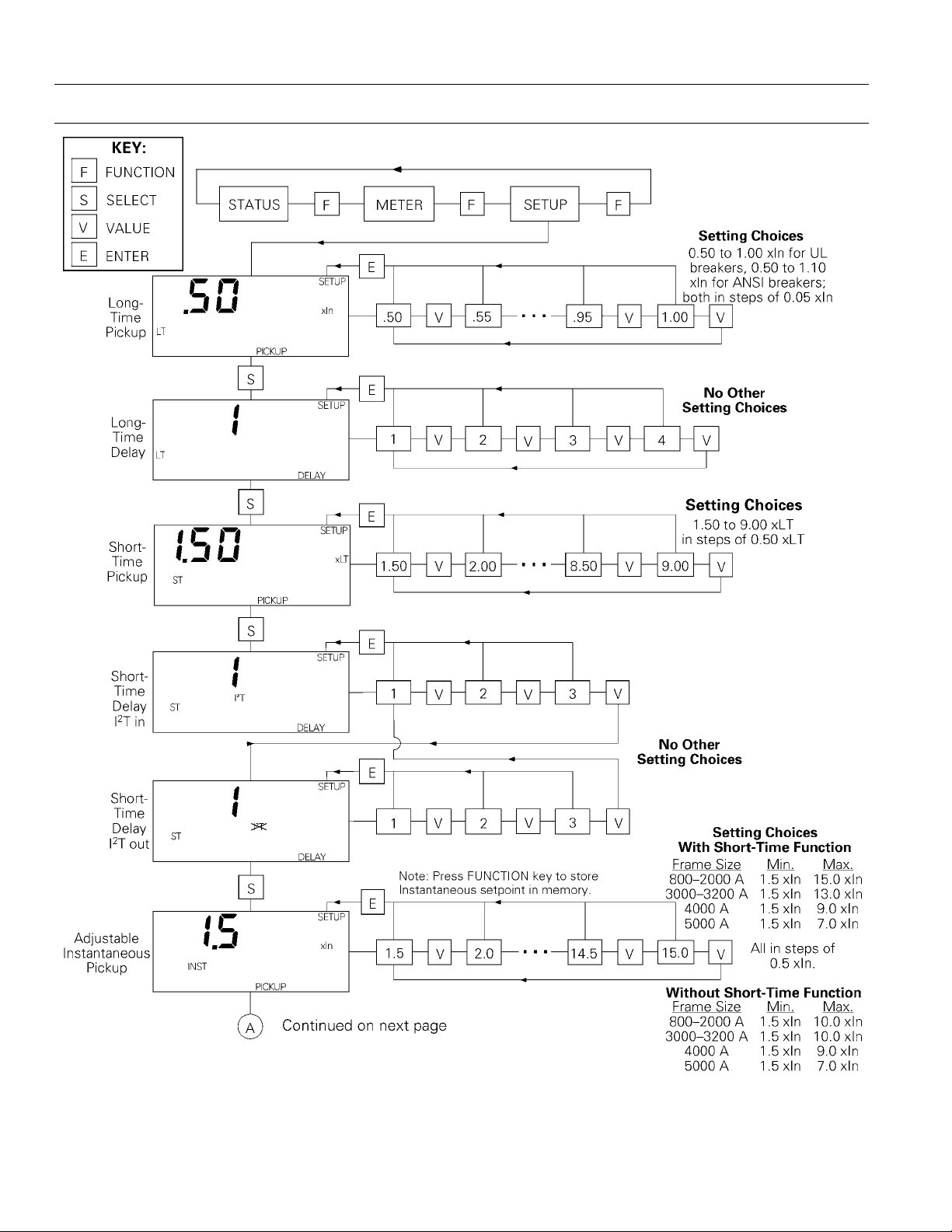
2-3 Setup Mode Operation
The following instructions describe setup procedures
for all available Trip Unit functions. These are illustrated in Figure 9. All Trip Units provide long-time
overcurrent protection, long-time delay, and some
form of instantaneous overcurrent protection when
installed in Power Break® circuit breakers. All other
functions are optional.
S
SELECT key on face of Trip Unit.
V
VALUE key on face of Trip Unit.
E
ENTER key on face of Trip Unit.
Table 9. Abbreviations used in setup procedure descriptions.
If a specific set of Trip Unit functions, such as relaying or short-time overcurrent protection, has not
been ordered, that function will not appear on the
Trip Unit display. Ignore setup mode instructions for
such functions.
The Trip Unit must be provided with control power
during setup. This can come from internal battery
power, from a MicroVersaTrip Portable Power Pack,
from an external +24 Vdc power supply, or by energizing the breaker to at least 20% of its sensor load.
To begin the process, press the
SETUP appears in the upper-right corner of the Trip
FUNCTION key until
Unit display. Setup mode always begins with longtime pickup. After a choice has been made for this
and each subsequent trip function, press
SELECT t o
advance to the next function.
10
Page 21
MicroVersaTrip Plus™ and MicroVersaTrip PM™ Trip Units
Chapter 2. Setup Mode
yy
KKKKeeeeyy
FUNCTION
SELECT
VALUE
ENTER
SSSSyyyymmmmbbbbooooll
F
S
V
E
ll
Select next programming
display
Display next set point or timedelay value
Store set point or time-delay
value into memory
SSSSeeeettttuuuupp
pp
Select one of three modes: Setup, Metering, Status
Table 10. Actions of function keys in Trip Unit operating modes.
Figure 8. Operation of FUNCTION key, showing progression among Trip Unit operating modes.
Set points are entered into memory in three steps:
display, select, and activate, as described below:
1111....Press the
VALUE key until the desired set point
is displayed flashing on the LCD.
2222....Press the
displayed value stops flashing and the
ENTER key to select this set point. The
SETUP
icon flashes on the LCD. This indicates that
the value has been stored in memory but is not
yet active. If a new set point is displayed but not
selected by pressing the
ENTER key (set point
value still flashing), then the displayed set
point is not entered into memory and the
original value is maintained. Multiple set point
changes can be made in this fashion without
changing the active settings. For each of these
changes, the
3333....Press the
settings in the Trip Unit. The
SETUP icon continues to flash.
FUNCTION key to activate these
SETUP icon no
longer flashes, which indicates that any
TTTTrrrriiiipppp UUUUnnnniiiitttt OOOOppppeeeerrrraaaattttiiiinnnngggg MMMMooooddddee
MMMMeeeetttteeeerrrriiiinnnngg
Select next metering display Select next status display
Display next phase value No effect
No effect No effect
ee
gg
SSSSttttaaaattttuuuuss
ss
selected settings are also currently active. The
FUNCTION key should always be pressed
following set point changes to ensure that the
active settings match the stored settings.
The set point change steps are summarized as
follows:
• Display set point – Press the
VALUE key until the
desired setting is flashing.
• Select set point – Press the
stops flashing and the
ENTER key; the setting
SETUP icon starts
flashing.
• Activate set points – Press the
activate the settings; the
FUNCTION key to
SETUP icon stops
flashing.
Always confirm settings on the Trip Unit after
making changes by exiting and re-entering Setup
mode and rechecking each changed setting.
11
Page 22
MicroVersaTrip Plus™ and MicroVersaTrip PM™ Trip Units
Chapter 2. Setup Mode
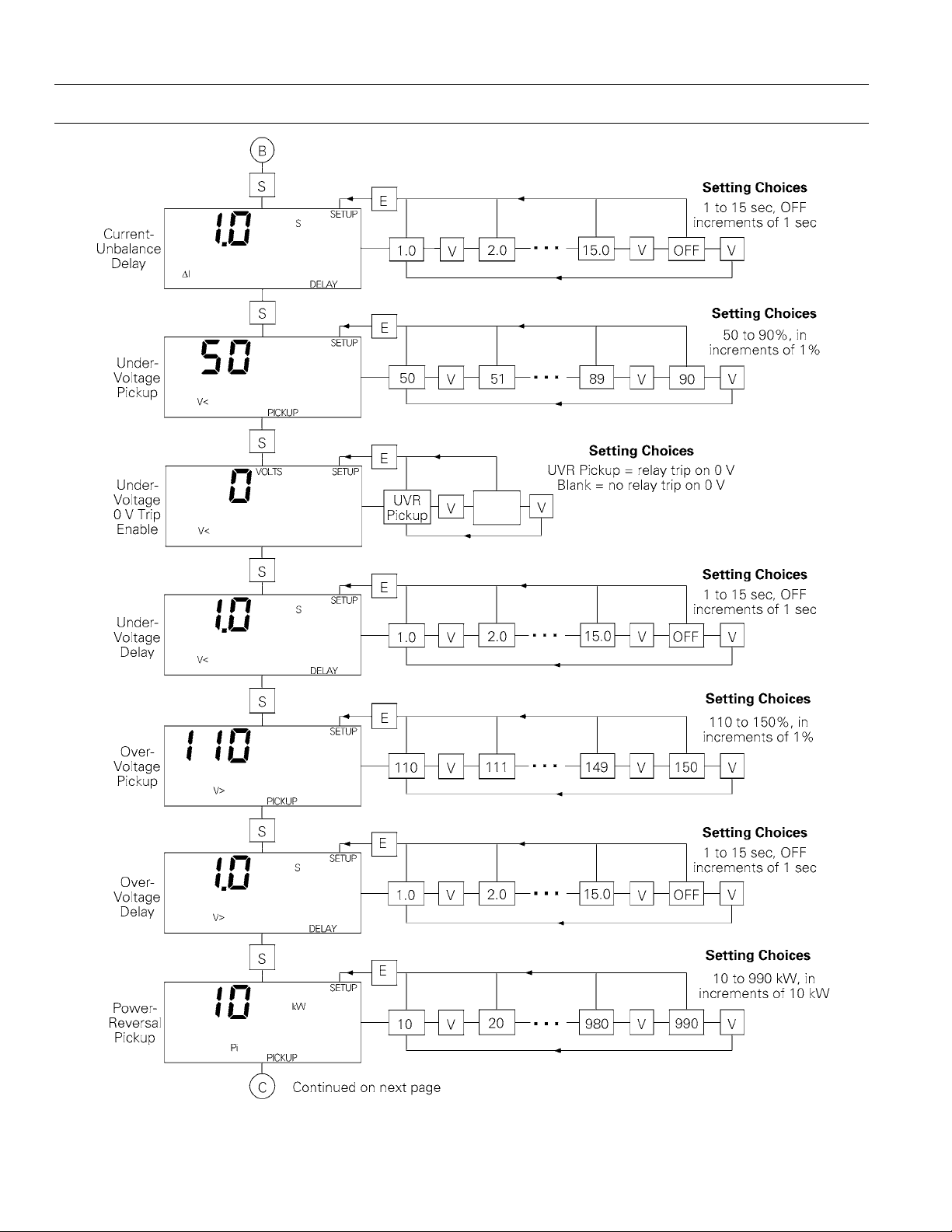
Figure 9. Trip Unit setup mode programming function flow.
12
Page 23
MicroVersaTrip Plus™ and MicroVersaTrip PM™ Trip Units
Chapter 2. Setup Mode
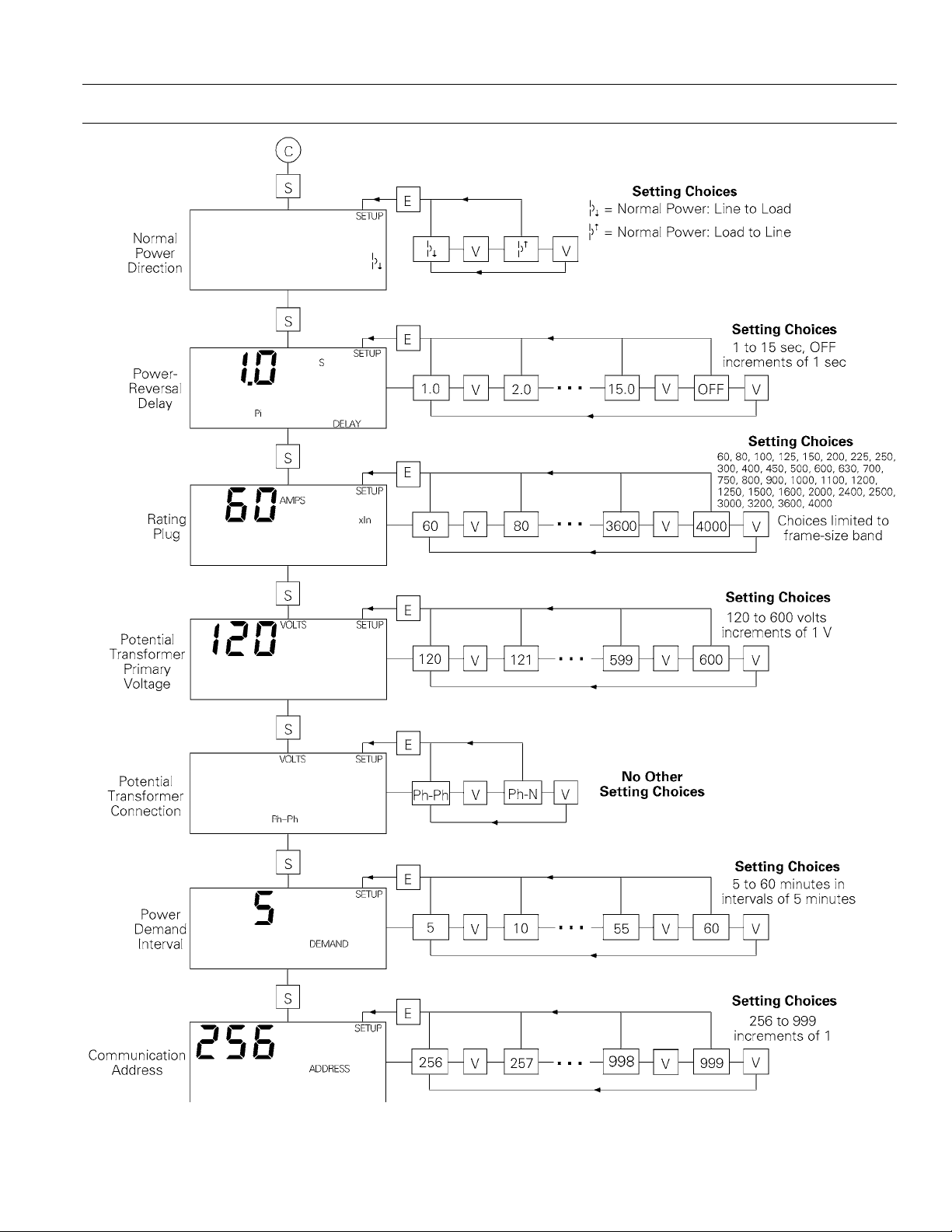
Figure 9. Trip Unit setup mode programming function flow (continued).
13
Page 24
MicroVersaTrip Plus™ and MicroVersaTrip PM™ Trip Units
Chapter 2. Setup Mode
Figure 9. Trip Unit setup mode programming function flow (continued).
14
Page 25
MicroVersaTrip Plus™ and MicroVersaTrip PM™ Trip Units
Chapter 2. Setup Mode
Figure 9. Trip Unit setup mode programming function flow (continued).
15
Page 26

MicroVersaTrip Plus™ and MicroVersaTrip PM™ Trip Units
Chapter 2. Setup Mode
Long-Time Pickup
The first setup-mode display is always the long-time
pickup setpoint, as illustrated in Figure 10. This set
point establishes the breaker’s nominal ampere rating,
xLT
, as a fraction of the rating plug value,
(
xLT
= LT multiplier x
scroll through the available choices. Press
store the desired set point.
Figure 10. Trip Unit display for long-time pickup.
The choices for UL breakers are 0.50 to 1.00 times
xln
in steps of 0.05. The pickup value tolerance band
is 0% to +20% of the set point.
The choices for ANSI breakers are 0.50 to 1.10 times
xln
, in steps of 0.05. The pickup value is defined for
−10% to +10% of the set point.
xIn
). Press the VALUE key to
xIn
ENTER to
in Table 11. Figure 13 illustrates the effect of this
delay on trip time. Press the
through the four choices of time-delay bands. Press
ENTER to store the desired value.
Figure 12. Trip Unit display for long-time delay.
BBBBaaaannnnddddDDDDeeeellllaaaayyyy,,,, sssseeeecc
1 2.4
2 4.9
3 9.8
420
Table 11. Lower-limit delays for long-time delay bands.
VALUE key to cycle
cc
Figure 11 illustrates the long-time pickup settings.
Figure 11. Time-current curve illustrating long-time pickup.
Long-Time Delay
The Trip Unit display for long-time delay is illustrated in Figure 12. This function allows normal
momentary overloads without nuisance tripping.
The time delays at the lower limit of the bands at
600% of the long-time current setting,
xLT
, are listed
Figure 13. Time-current curve illustrating long-time delay.
Short-Time Pickup
The short-time pickup function establishes the current at which short-time trip is activated. Short-time
pickup is coupled with long-time pickup and the
choices of pickup settings are from 1.5 to 9.0 times
the long-time setting,
Trip Unit display is illustrated in Figure 14.
xLT
, in steps of 0.5
xLT
. The
16
Page 27

MicroVersaTrip Plus™ and MicroVersaTrip PM™ Trip Units
Chapter 2. Setup Mode
Figure 14. Trip Unit display for short-time pickup coupled with
long-time pickup.
The time-current curve for short-time pickup is
shown in Figure 15.
Figure 15. Time-current curve illustrating short-time pickup.
Short-Time Delay
The Trip Unit display for short-time delay is shown
in Figure 16. This function delays the breaker trip on
a short-time trip. The choices of time-delay bands
are listed in Table 12. The delay with
current of 600% of
band. The delay with
xLT
at the lower limit of the
I2T OUT is for the lower limit of
each band.
I2T IN is for a
Figure 16. Trip Unit display for short-time delay.
dd
BBBBaaaannnndd
1 0.10
2 0.21
3 0.35
TTTTiiiimmmmeeee DDDDeeeellllaaaayyyyssss,,,, sssseeeecc
Table 12. Lower-limit delays for I
2
T OUT short-time delay bands.
cc
Figure 17. Time-current curve for short-time delay with I
2
T OUT.
On ANSI Trip Units ordered with the user-selectable,
switchable instantaneous overcurrent and groundfault option, “X,” an additional value of
at the end of the delay band settings. Choosing
OFF appears
OFF
disables short-time protection. The short-time OFF
band is interlocked with instantaneous pickup, so
that only one function can be turned off at a time.
I2T OUT function, illustrated in Figure 17, estab-
The
lishes a constant time delay.
I2T IN biases the delay
with a constant slope, as shown in Figure 18.
Figure 18. Time-current curve for short-time delay with I
17
2
T IN.
Page 28

MicroVersaTrip Plus™ and MicroVersaTrip PM™ Trip Units
Chapter 2. Setup Mode
Instantaneous Pickup
Instantaneous overcurrent protection, with Trip Unit
display illustrated in Figure 19, causes an immediate
breaker trip when the chosen current level is
reached. The pickup value may be set in steps of 0.5
xIn
from 1.5
frame size and the presence of the short-time
function, as listed in Table 13.
Note the difference from short-time pickup, which is
based on a multiple of
characteristic is shown in Figure 20.
Figure 19. Trip Unit display for instantaneous pickup.
xIn
to a maximum dependent on the
xLT
. The time-current
the listing of numerical values. Choose this setting to
disable instantaneous protection. The instantaneous
OFF selection is interlocked with short-time pickup,
so that only one function can be turned off at a time.
High-Range Instantaneous Overcurrent
Protection
High-range instantaneous overcurrent protection
has a fixed trip setting equal to the breaker frame’s
short-time withstand rating,
H
, with pickup tolerance
+0%, –20%. When this option is installed, skip programming of instantaneous pickup and go on to the
next function by pressing
SELECT.
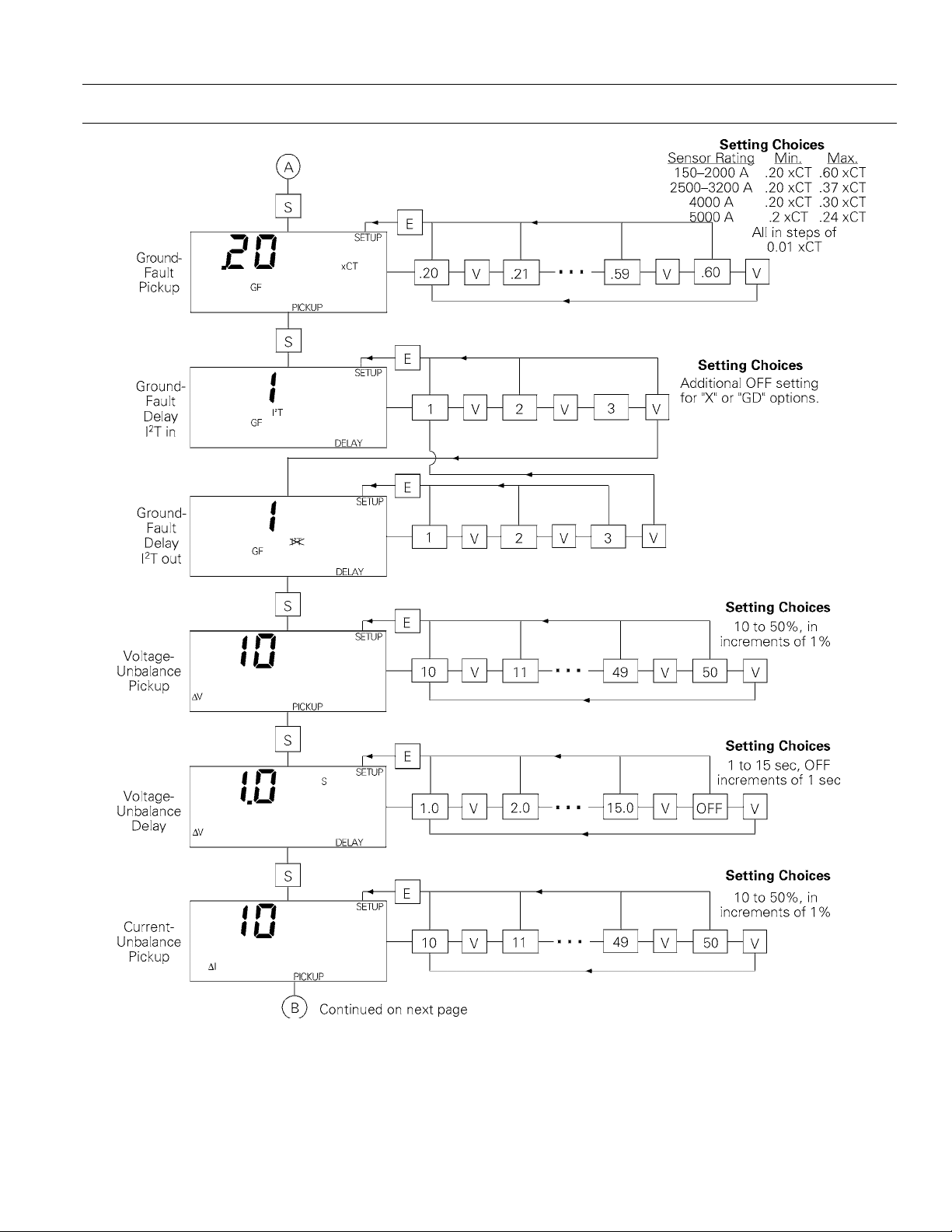
Ground-Fault Pickup
The trip unit display for ground-fault pickup is
shown in Figure 21. This function sets the pickup
current for ground-fault protection. The available
settings are listed in Table 14 as multiples of
current sensor rating, in steps of 0.01
maximum value is limited to 1200 A. Figure 22
illustrates the time-current curve for ground-fault
pickup.
xCT
xCT
the
. The
Figure 20. Instantaneous overcurrent protection set point.
FFFFrrrraaaammmmeeee MMMMaaaaxxxx.... AAAAmmmmpp
RRRRaaaattttiiiinnnngg
2000 1.5–10.0
3200 1.5–10.0
4000 1.5–9.0
5000 1.5–7.0
pp
gg
SSSSeeeettttppppooooiiiinnnnttttss
WWWWiiiitttthhhhoooouuuutttt SSSSTT
ss
xIn
xIn
xIn
xIn
SSSSeeeettttppppooooiiiinnnnttttss
TT
WWWWiiiitttthhhh SSSSTT
1.5–15.0
1.5–13.0
1.5–9.0
1.5–7.0
ss
TT
xIn
xIn
xIn
xIn
Table 13. Instantaneous pickup settings for various frame sizes
with and without the short-time function.
On Trip Units with the user-selectable switchable
instantaneous overcurrent and ground-fault option,
X, an additional value of
OFF appears at the end of
Figure 21. Trip Unit display for ground-fault pickup.
SSSSeeeennnnssssoooorrrr,,,, AA
150–2000 0.20–0.60
2500–3200 0.20–0.37
AA
4000 0.20–0.30
SSSSeeeetttt PPPPooooiiiinnnnttttss
ss
Table 14. Ground-fault pickup settings, as a function of sensor
rating.
18
Page 29

MicroVersaTrip Plus™ and MicroVersaTrip PM™ Trip Units
Chapter 2. Setup Mode
Figure 22. Time-current curve for ground-fault pickup.
Ground-Fault Delay
This function sets the delay before the breaker trips
when the ground-fault pickup current has been
detected. The Trip Unit display is shown in Figure
23. The choices are listed in Table 15. The delay for
I2T OUT is at the lower limit of each band. The delay
for
I2T IN is at 200% of the pickup setting at the lower
limit of the band.
BBBBaaaannnnddddTTTTiiiimmmmeeee DDDDeeeellllaaaayyyy,,,, sssseeeecc
OFF Disabled
1 0.10
2 0.21
3 0.35
cc
Table 15. Lower-limit delays for ground-fault delay bands.
Figure 24. Time-current curve for ground-fault delay with I
OUT
.
2
T
I2T OUT function establishes a constant time
The
delay, as shown in Figure 24.
I2T IN biases the delay
with a constant slope, as shown in Figure 25.
With the X or GD options (switchable ground fault),
an
OFF selection appears as an additional time-delay
set point. Selecting
OFF disables ground-fault protec-
tion.
Figure 23. Trip Unit display for ground-fault delay, showing I
2
out.
Figure 25. Time-current curve for ground-fault delay with I
T
Voltage-Unbalance Relay Pickup
This function compares the highest or lowest phase
voltage with the average of all three phases and
initiates a trip if the difference exceeds the set point.
The true rms voltage is computed for each phase.
The range of set points is from 10 to 50% of the
unbalance, with an increment of 1%. The Trip Unit
display is shown in Figure 26.
2
T IN.
19
Page 30

MicroVersaTrip Plus™ and MicroVersaTrip PM™ Trip Units
Chapter 2. Setup Mode
Figure 26. Trip Unit display for voltage-unbalance relay pickup.
Voltage-Unbalance Relay Delay
This function sets the delay time before a voltageunbalance trip occurs. The range of delays is 1 to 15
seconds, in steps of 1 second. Choosing
voltage-unbalance protection. The Trip Unit display
is shown in Figure 27.
Figure 27. Trip Unit display for voltage-unbalance relay delay.
OFF disables
Current-Unbalance Relay Pickup
This function compares the true RMS current in the
highest or lowest phase with the average of all three
phases and initiates a trip if the difference exceeds
the set point. The range of set points is 10 to 50% of
the unbalance, with an increment of 1%. The Trip
Unit display is shown in Figure 28.
Figure 29. Trip Unit display for current-unbalance relay delay.
Undervoltage Relay Pickup
This function measures the true rms voltage in all
phases and initiates a trip if any phase voltage drops
below the set point. The range of set points is 50 to
90% of the nominal voltage, with an increment of
1%. The Trip Unit display is shown in Figure 30.
Figure 30. Trip Unit display for undervoltage relay pickup.
Undervoltage Relay Zero-Volt Trip Enable
This function determines if the relay trips when all
three phase voltages drop to zero volts. The Trip
Unit display for zero-volt trip disabled is shown in
Figure 31. The Trip Unit display for zero-volt trip
enabled is shown in Figure 32.
Figure 28. Trip Unit display for current-unbalance relay pickup.
Current-Unbalance Relay Delay
This function sets the delay time before a currentunbalance trip occurs. The range of delays is 1 to 15
seconds, in steps of 1 second. Choosing
current-unbalance protection. The Trip Unit display
is shown in Figure 29.
OFF disables
Figure 31. Trip Unit display for undervoltage relay zero-volt trip
disabled.
20
Page 31

MicroVersaTrip Plus™ and MicroVersaTrip PM™ Trip Units
Chapter 2. Setup Mode
Figure 32. Trip Unit display for undervoltage relay zero-volt trip
enabled.
Undervoltage Relay Delay
This function sets the delay time before an undervoltage trip occurs. The range of delays is 1 to 15
seconds, in steps of 1 second. Choosing
undervoltage protection. The Trip Unit display is
shown in Figure 33.
Figure 33. Trip Unit display for undervoltage relay delay.
OFF disables
Overvoltage Relay Pickup
This function measures the true rms voltage in all
phases and initiates a trip if any phase voltage
exceeds the set point. The range of set points is 110
to 150% of the nominal voltage, with an increment
of 1%. The Trip Unit display is shown in Figure 34.
Figure 35. Trip Unit display for overvoltage relay delay.
Power-Reversal Relay Pickup
This function measures the direction of power flow
through the breaker and initiates a trip if a sufficient
magnitude of reverse power is detected. The range of
set points is 10 kW to 990 kW, in steps of 10 kW. The
Trip Unit display is shown in Figure 36.
Figure 36. Trip Unit display for power-reversal relay pickup.
Power Direction Setup
This function selects the normal power flow direction for the breaker, either from line to load or from
load to line. Figure 37 shows the setup display for
normal power flow of line to load. This direction
setup also affects the sign of the normal power
metering displays.
Figure 34. Trip Unit display for overvoltage relay pickup.
Overvoltage Relay Delay
This function sets the delay time before an overvoltage trip occurs. The range of delays is 1 to 15 seconds, in steps of 1 second. Choosing
overvoltage protection. The Trip Unit display is
shown in Figure 35.
OFF disables
Figure 37. Trip Unit display for power direction setup, showing
line to load.
Power-Reversal Relay Delay
This function sets the delay time before a powerreversal trip occurs. The range of delays is 1 to 15
seconds, in steps of 1 second. Choosing
21
OFF disables
Page 32
MicroVersaTrip Plus™ and MicroVersaTrip PM™ Trip Units
Chapter 2. Setup Mode
power-reversal protection. The Trip Unit display is
shown in Figure 38.
Figure 38. Trip Unit display for power-reversal relay delay.
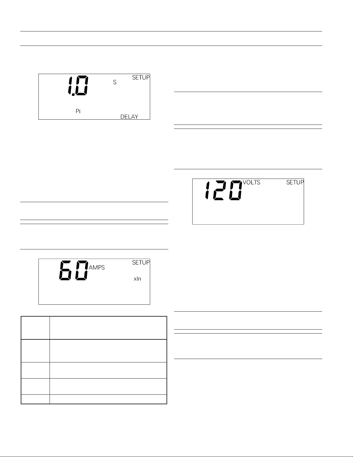
Rating Plug Current Setting
The Trip Unit display for rating plug setting is
shown in Figure 39. Enter the current setting of the
rating plug by scrolling through the list with
and pressing ENTER when the correct value is
reached. Table 16 lists the available rating plugs for
the various Trip Units.
CCCCAAAAUUUUTTTTIIIIOOOONNNN::
::
Incorrect storage of this set point will
result in incorrect metering values.
VALUE
Potential Transformer Primary Voltage
Enter the primary voltage rating of the potential
transformer, as illustrated in Figure 40. The range of
values is 120 to 600 volts, with an increment of 1 volt.
CCCCAAAAUUUUTTTTIIIIOOOONNNN::
result in incorrect metering values. Even if this setting is entered remotely, it must be entered again
locally.
AAAATTTTTTTTEEEENNNNTTTTIIIIOOOONNNN::
enregistrée pour ce réglage, les mesures seront
fausses. Cette valeur doit être enregistrée locallement
même dans le cas d’une utilisation à distance avec
commnet.
::
Incorrect storage of this set point will
::
Si une valeur incorrecte est
AAAATTTTTTTTEEEENNNNTTTTIIIIOOOONNNN::
::
Si une valeur incorrecte est
enregistrée pour ce réglage, les mesures seront
fausses.
Figure 39. Trip Unit display for rating plug current set point.
rr
BBBBrrrreeeeaaaakkkkeeeerr
ee
FFFFrrrraaaammmmee
SSSSiiiizzzzeeeeRRRRaaaattttiiiinnnngggg PPPPlllluuuugggg OOOOppppttttiiiioooonnnnssss,,,, AAAAmmmmppppss
60, 80, 100, 125, 150, 200, 225, 250, 300, 400,
800–2000
A
2500–320
0 A
4000 A
5000 A 3200, 4000, 5000
450, 500, 600, 630, 700, 750, 800, 900, 1000,
1100, 1200, 1250, 1500, 1600, 2000
1200, 1500, 1600, 2000, 2400, 2500, 3000,
3200
1600, 2000, 2400, 2500, 3000, 3200, 3600,
4000
ss
Figure 40. Trip Unit display for potential transformer primary
voltage set point.
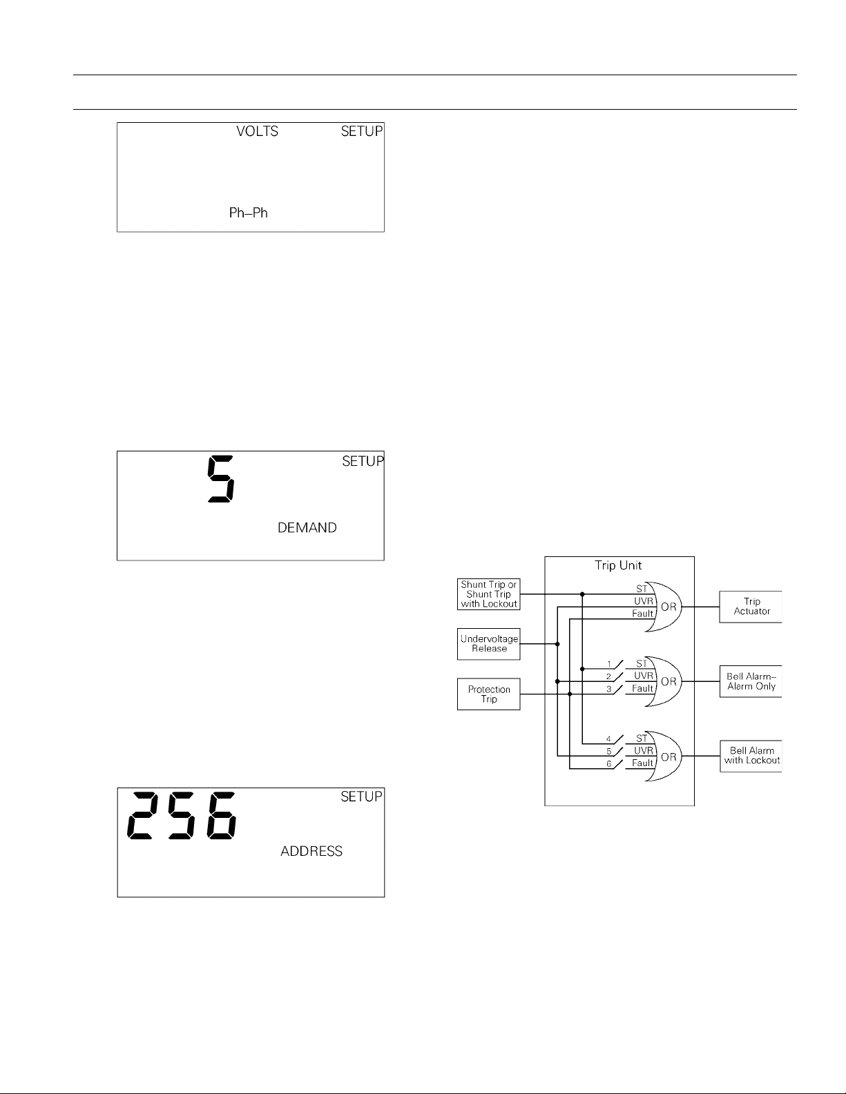
Potential Transformer Connection
Note that this step applies only to MicroVersaTrip
PM Trip Units.
Select the appropriate potential transformer connection, either line-to-line (
(
Ph-N), as illustrated in Figure 41.
CCCCAAAAUUUUTTTTIIIIOOOONNNN::
::
Incorrect storage of this set point will
result in incorrect metering values.
AAAATTTTTTTTEEEENNNNTTTTIIIIOOOONNNN::
::
Si une valeur incorrecte est
enregistrée pour ce réglage, les mesures seront
fausses.
Ph-Ph) or line-to-neutral
Table 16. Trip Unit rating plug options.
22
Page 33
MicroVersaTrip Plus™ and MicroVersaTrip PM™ Trip Units
Chapter 2. Setup Mode
Figure 41. Trip Unit display for potential transformer
connection choice.
Power Demand Intervals
This function sets the power demand interval, which
can be in the range of 5 to 60 minutes, in steps of 5
minutes. This setpoint specifies the time interval for
power demand averaging. The Trip Unit calculates a
rolling average of breaker power over this time interval. The Trip Unit display is illustrated in Figure 42.
MicroVersaTrip PM Trip Unit. Simply press
identify the unit to the FPU.
the FPU’s display must not be changed at the
breaker.
The address shown on
ENTER to
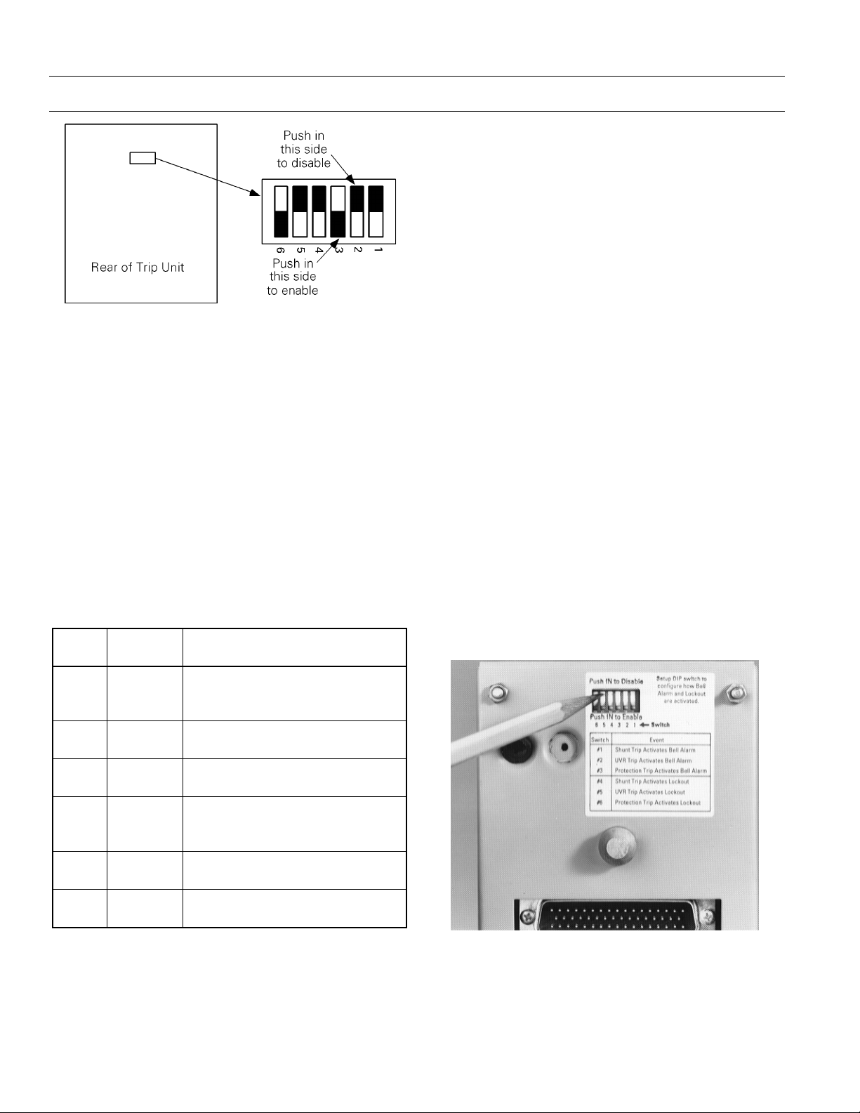
Accessory Configuration Setup (RMS9D
Series Trip Units Only)
RMS9D Trip Units have a six-position DIP switch
module on the rear of the unit that controls the configuration of the Power Break® II integrated accessories. These switches can be set up to define the types
of signals (protection trip, Shunt trip, Shunt Trip
with Lockout, or Undervoltage Release trip) that
activate the Bell Alarm–Alarm Only and Bell Alarm
with Lockout accessories on the Power Break II
breaker. Each of the six switches enables or disables
a different path to activate these accessories from the
different types of trip signals. Figure 44 shows the
logic function for the switches.
The Trip Unit DIP switches are illustrated in Figure
45, with the factory settings shown. Table 17 lists the
switch functions.
Figure 42. Trip Unit display for power demand interval.
Communication Address
Note that this step applies only to MicroVersaTrip
PM Trip Units connected to either POWER
LEADER™ or Epic MicroVersaTrip systems.
With POWER LEADER systems, the address is
assigned at the breaker. The address options are
from 256 to 999, in steps of 1, as illustrated in Figure
43.
Figure 43. Trip Unit display for setting communication address.
With Epic MicroVersaTrip systems, the Field
Programming Unit (FPU) calls for removal of the
rating plug. This is not required for addressing a
Figure 44. Logic diagram for accessory configurations.
23
Page 34
MicroVersaTrip Plus™ and MicroVersaTrip PM™ Trip Units
Chapter 2. Setup Mode
3333....When a protection trip (long-time, short-time,
instantaneous, ground-fault, or protectiverelay) occurs, the contacts of the Bell
Alarm–Alarm Only also change state. The
Figure 45. Accessory configuration switch on rear of Trip Unit,
showing factory settings (solid part indicates that switch is
pushed in on that side).
Description of Switch Settings
Following are descriptions of the effects of each
accessory switch when it is
enabled
:
1111....When a Shunt Trip or Shunt Trip with Lockout
accessory causes the breaker to trip, the
contacts of the Bell Alarm–Alarm Only also
change state. The factory switch setting is
disabled
.
2222....When an Undervoltage Release accessory
causes the breaker to trip, the contacts of the
Bell Alarm–Alarm Only also change state. The
factory switch setting is
yy
FFFFaaaaccccttttoooorrrryy
hh
SSSSwwwwiiiittttcccchh
1 Disabled
2 Disabled
3 Enabled
4 Disabled
5 Disabled
6 Enabled
SSSSeeeettttttttiiiinnnnggggFFFFuuuunnnnccccttttiiiioooonn
Shunt Trip or Shunt Trip with
Lockout activates Bell
Alarm–Alarm Only
UVR trip activates Bell
Alarm–Alarm Only
Protection trip activates Bell
Alarm–Alarm Only
Shunt Trip or Shunt Trip with
Lockout activates Bell Alarm with
Lockout
UVR trip activates Bell Alarm with
Lockout
Protection trip activates Bell
Alarm with Lockout
disabled
nn
.
factory switch setting is
4444....When the Shunt Trip or Shunt Trip with
Lockout accessory causes the breaker to trip,
the contacts of the Bell Alarm with Lockout
also change state. The factory switch setting is
disabled
.
5555....When the Undervoltage Release accessory
causes the breaker to trip, the contacts of the
Bell Alarm with Lockout also change state. The
factory switch setting is
6666....When a protection trip (long-time, short-time,
instantaneous, ground-fault, or protectiverelay) occurs, the contacts of the Bell Alarm
with Lockout also change state. The factory
switch setting is
enabled
To change switch settings on RMS9D series Trip
Units, refer to Chapter 5 to remove the Trip Unit
from the breaker. Push in the appropriate Enable or
Disable side of the switch to configure the accessories, as shown in Figure 46, and carefully reinstall the
Trip Unit. Verify that the new switch settings are
correct by testing the breaker responses to
Undervoltage Release trips and Shunt trips.
enabled
disabled
.
.
.
Table 17. Accessory configuration switch settings, including
factory defaults.
Figure 46. Setting the accessory configuration switches.
24
Page 35
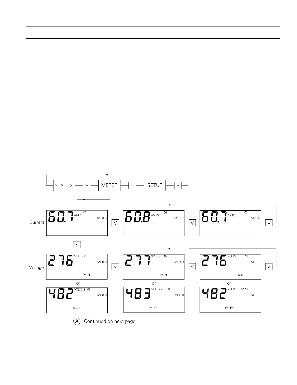
MicroVersaTrip Plus™ and MicroVersaTrip PM™ Trip Units
Chapter 3. Metering Mode
3-1 Overview
The metering mode displays parameter values for
that part of the electrical system controlled by the
breaker’s MicroVersaTrip Plus or MicroVersaTrip
PM Trip Unit. Both currents and voltages are computed as true rms values. There is no loss of accuracy
even in the presence of high levels of harmonics. All
metering displays are updated once each second.
Accuracies and resolutions are described in Section
1-8 and Table 7.
All values except frequency are displayed to three
significant figures. For example, phase currents
might be displayed as 60.7
KA.
The Trip Unit metering displays are appropriate to
the actual configuration ordered. All MicroVersaTrip Plus and MicroVersaTrip PM Trip Units
AMPS, 492 AMPS, or 1.22
include current metering. Two configurations of the
MicroVersaTrip PM Trip Units (with PM and M
suffixes in their catalog numbers) have the full
complement of metering displays.
The Trip Unit must be provided with control power
to display metered values. This can come from internal battery power, from a MicroVersaTrip Portable
Power pack, from an external +24 Vdc power supply,
or by energizing the breaker to at least 20% of its
sensor load.
3-2 Metering Mode Operation
Metering mode is reached by pressing FUNCTION
until METER appears in the upper-right corner of the
display. Metering mode always begins with the phase
currents. The sequence in which the metered values
appear is illustrated in Figure 47.
Figure 47. Trip Unit metering mode function flow.
25
Page 36
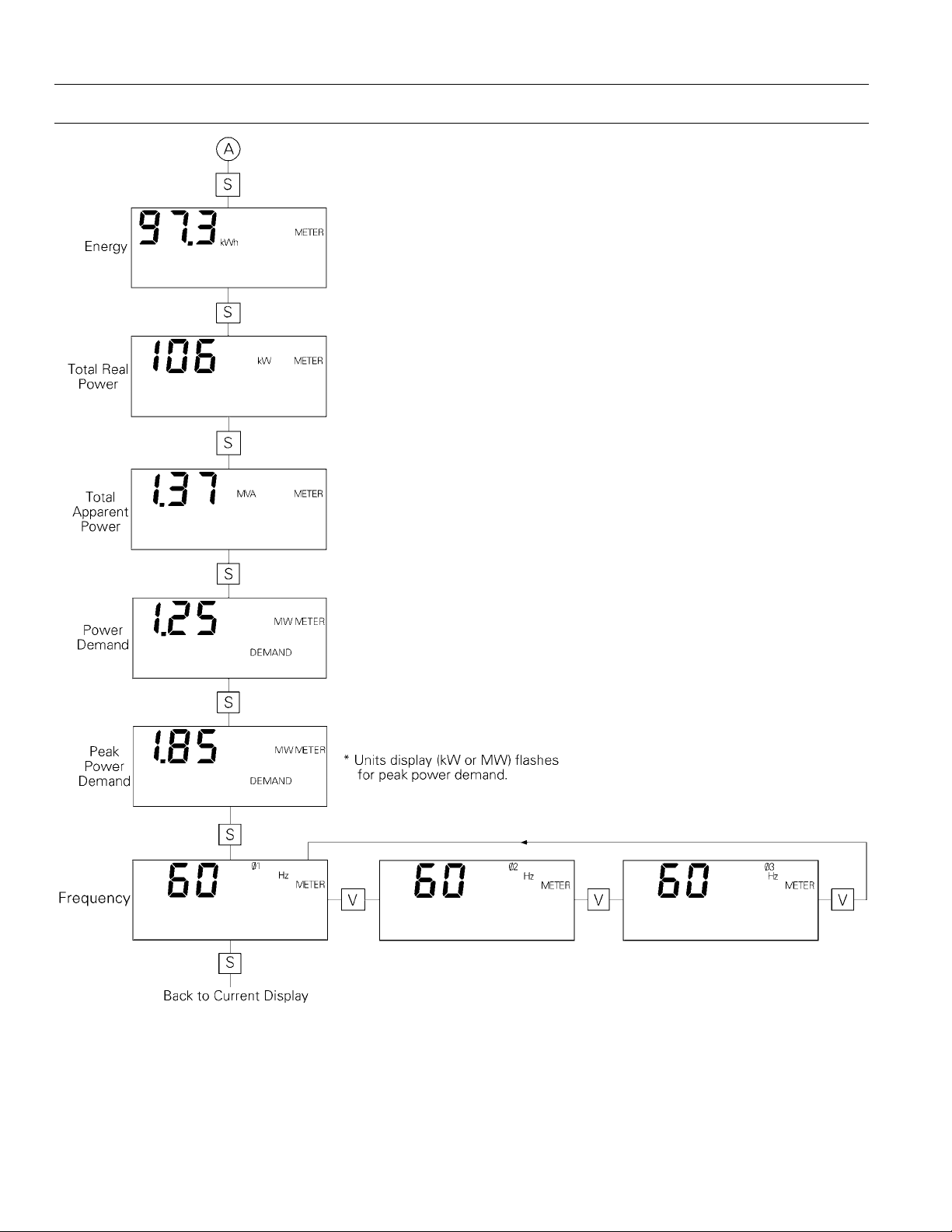
MicroVersaTrip Plus™ and MicroVersaTrip PM™ Trip Units
Chapter 3. Metering Mode
Figure 47. Trip Unit metering mode function flow (continued).
26
Page 37
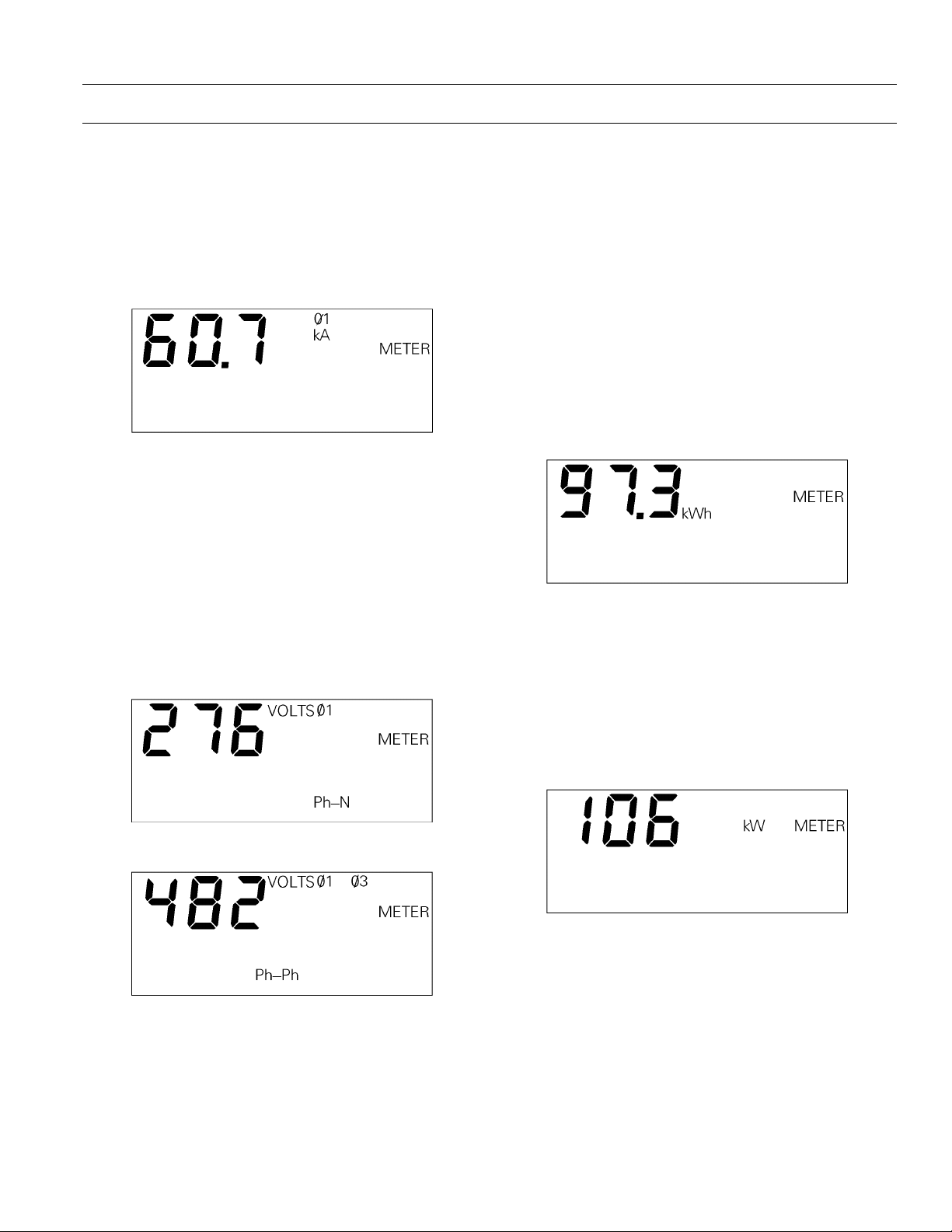
MicroVersaTrip Plus™ and MicroVersaTrip PM™ Trip Units
Chapter 3. Metering Mode
Current
The initial metering display is phase 1 line current,
as illustrated in Figure 48. Press
among the three phases. Current is displayed from 0
to 999 amperes and from 1.00 to a maximum of 999
kA. For current values less than 5% of the current
sensor rating, the displayed value is zero.
Figure 48. Trip Unit display for current metering.
VALUE to cycle
Voltage
The voltage displayed by this function depends on
how the Trip Unit was configured during Setup. If
the breaker was configured with phase-to-neutral
connections, the display shows individual phase voltages, as in Figure 49. If the breaker was configured
with phase-to-phase connections, the display shows
voltages between the phases, as in Figure 50. Press
VALUE to cycle through the three phase voltages.
Energy
This display, illustrated in Figure 51, shows the
aggregate energy flow through the breaker. The
value is displayed from 0 to 999 kWh, then automatically switches units to display 1.00 to 999 Mwh, and
then again to display 1.00 to 999 GWh. When 999
GWh is exceeded, the display switches back to 0
kWh. The largest negative energy value displayed is
−99 GWh.
Accumulated energy is stored in nonvolatile memory. The value in the display can be reset through
the Trip Unit keypad. To reset the energy value,
hold down the
The displayed energy value will reset to zero.
Figure 51. Trip Unit display for aggregate energy.
VALUE key and press the SELECT key.
Total Real Power
The value displayed for total real power, illustrated
in Figure 52, represents the aggregate real power in
watts flowing through all three phases. The value is
displayed from 0 to 999 kW, then automatically
switches units to display 1.00 to 999 MW.
Figure 49. Trip Unit display for line-to-neutral voltages.
Figure 50. Trip Unit display for line-to-line voltages.
Figure 52. Trip Unit display for aggregate real power.
27
Page 38
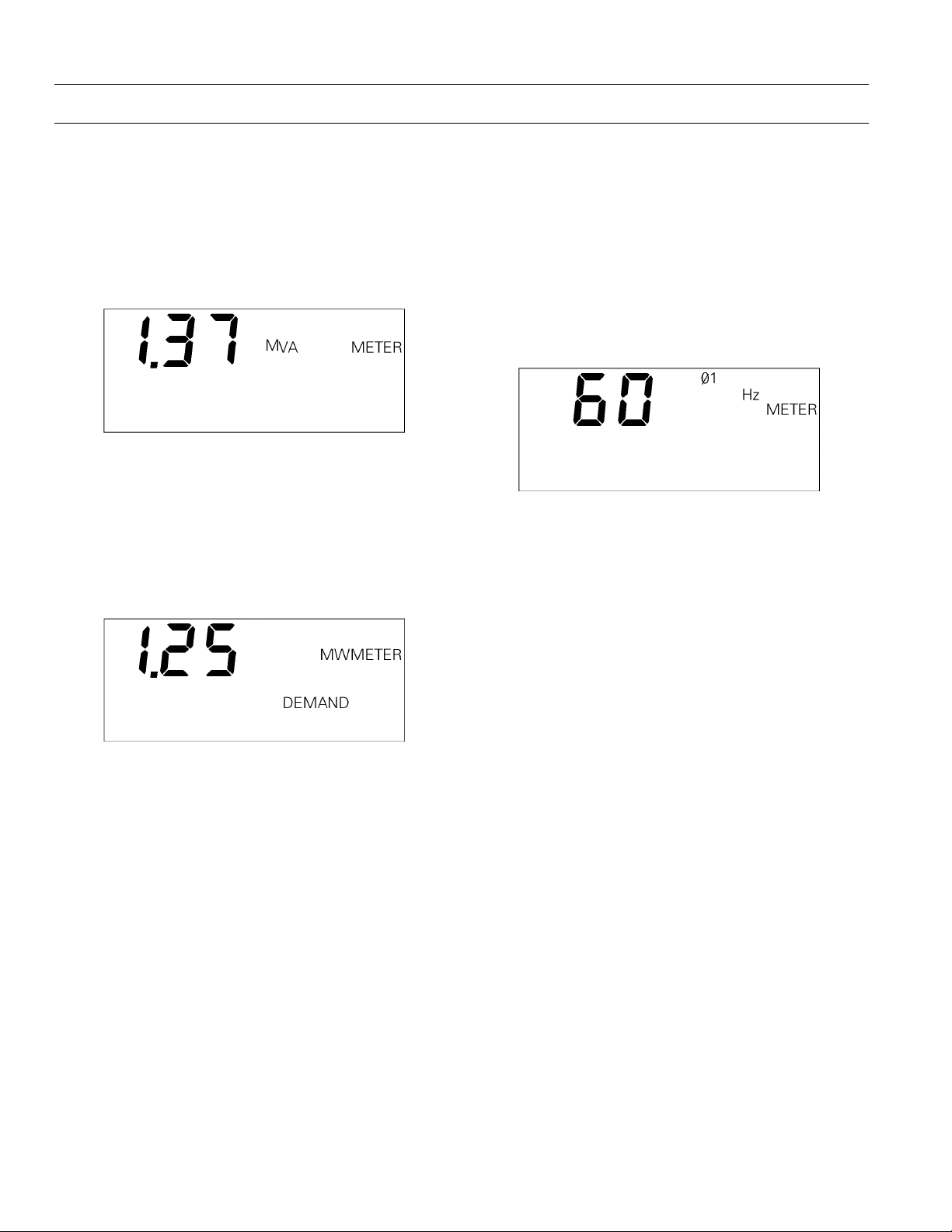
MicroVersaTrip Plus™ and MicroVersaTrip PM™ Trip Units
Chapter 3. Metering Mode
Total Apparent Power
The value displayed for total apparent power, as
illustrated in Figure 53, represents the aggregate
total apparent power in volt-amperes flowing
through all three phases. The value is displayed from
0 to 999 kVA, then automatically switches units to
display 1.00 to 999 MVA.
Figure 53. Trip Unit display for aggregate apparent power.
Power Demand
Power demand is the average of total power over the
selected interval (5, 10, …, 55, 60 minutes). This display is updated every minute. The power demand
display is illustrated in Figure 54.
Frequency
This display, illustrated in Figure 55, shows the frequency of the line current. Either line voltage or
current must be present for this display to appear.
The frequency is calculated from the current and
voltage signals. If both are present, the voltage frequency is displayed. If neither are present, this display does not appear.
The frequency is displayed in steps of 1 Hz.
Figure 55. Trip Unit display for frequency.
Figure 54. Trip Unit display for power demand.
Peak Power Demand
Peak power demand is stored in nonvolatile memory.
Every minute, the power demand is calculated and
compared against the stored peak power demand. If
the new power demand is greater than the stored
peak demand, the Trip Unit stores the new power
demand as the peak value. The display of peak
power demand is identical to the display illustrated
in Figure 54, except that the units segment (in this
case, MW) flashes.
Peak demand is stored in nonvolatile memory. The
value in the display can be reset through the Trip
Unit keypad. To reset the peak demand to the present demand, hold down the
SELECT key.
VALUE key and press the
28
Page 39

MicroVersaTrip Plus™ and MicroVersaTrip PM™ Trip Units
Chapter 4. Status Mode
4-1 Overview
Trip Unit Status mode is selected by pressing the
FUNCTION key until STATUS appears on the display.
Status mode indicates the present status of the Trip
Unit and circuit breaker. It also displays information
about trip conditions and the trip history of the
breaker. Two categories of information can be
displayed: trip information and trip operations
counters.
Trip Information
Various trip information parameters are displayed
when an overcurrent trip or protective relay trip
occurs. Additionally, RMS9D series Trip Units provide target indications if a breaker Undervoltage
Release or Shunt Trip accessory trip occurs.
The Status display indicates when a long-time, shorttime, or ground-fault trip is imminent (breaker is in
pickup). Following a trip, the Trip Unit displays a
trip target to indicate the type of trip, the fault current magnitude at trip, and the phase of the fault
(where appropriate). For adjustable-instantaneous
trips, the Trip Unit displays the instantaneous function setpoint rather than the actual current. Fault
magnitude is not displayed for high-range instantaneous trips.
long-time, short-time, adjustable-instantaneous, and
ground-fault. The corresponding counter is incremented after any of these trips. A maximum of 256
trips can be counted for each type of fault, after
which the counter rolls over to zero.
4-2 Status Mode Operation
This section describes each of the Status mode displays.
Normal Status Display
When the breaker is closed and its circuit energized,
the normal status display appears, as illustrated in
Figure 56. This display indicates that the Trip Unit is
not in long-time pickup and that all trip targets are
cleared.
Figure 56. Trip Unit display for normal status.
Trip information is stored in the Trip Unit memory
and displayed when Trip Unit power is returned or if
internal battery power is enabled. Trip information
is always available if Trip Unit power is maintained
following a fault.
The Status display records trip information only for
those options ordered with the Trip Unit. For example, only MicroVersaTrip PM Trip Units can be
equipped with protective relays and thus display
information about them.
RMS9D series Trip Units only display trip targets for
Undervoltage Release and Shunt Trip accessory trips
when those accessory modules are installed in the
Power Break® II breaker.
Trip Operations Counters
Trip operations counters record the total number of
overcurrent trips. Separate internal counters are
provided for each of the following types of trips:
Long-Time Overcurrent Pickup Display
When the long-time overcurrent function has
reached 95% of the Trip Unit’s long-time current
rating,
illustrated in Figure 57. During the transition from
95% to 100% of the set point, the frequency of flashing increases. When the set point is reached, but
before the time delay has expired, the flashing stops,
indicating that tripping is imminent.
29
xLT
, PICKUP begins to flash on the display, as
Page 40
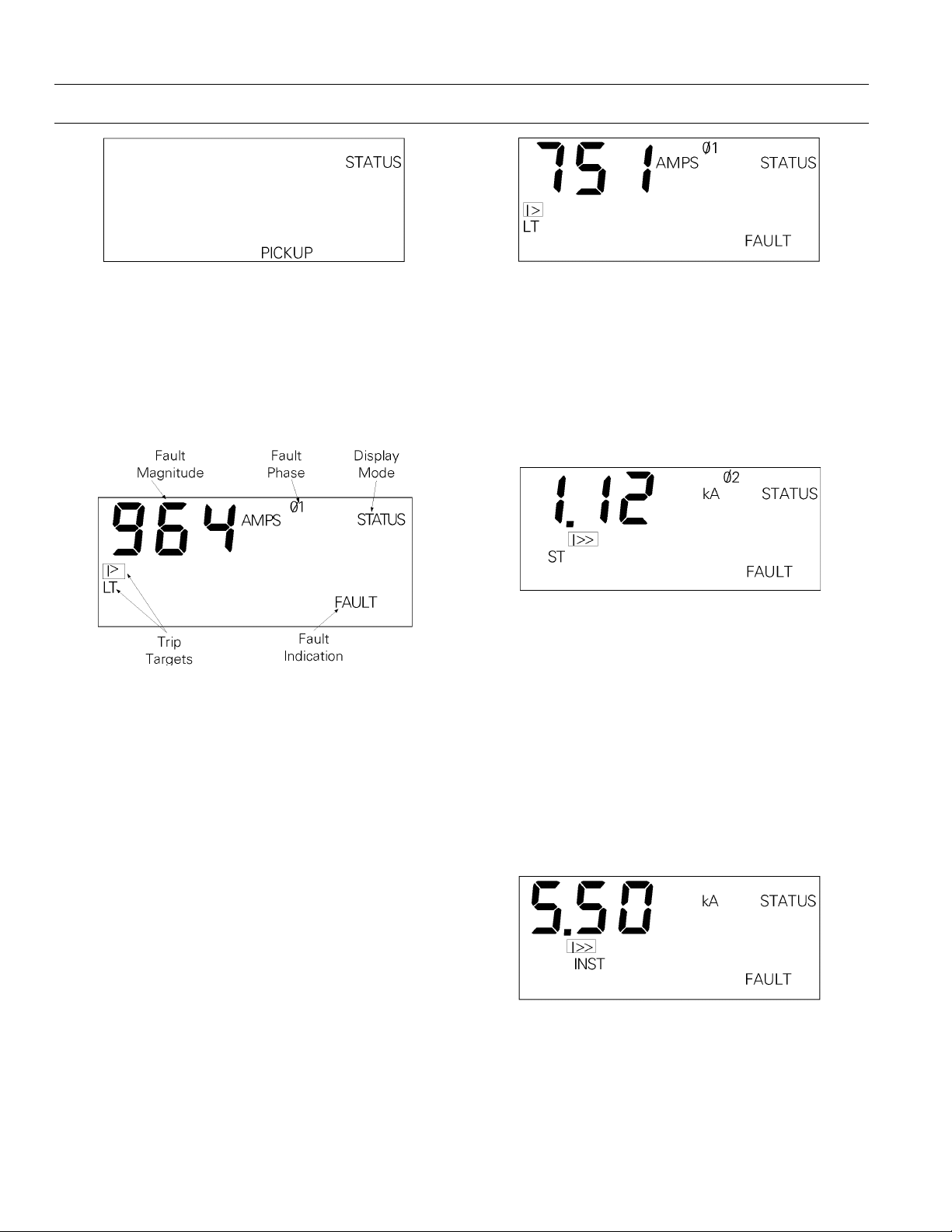
MicroVersaTrip Plus™ and MicroVersaTrip PM™ Trip Units
Chapter 4. Status Mode
Figure 57. Trip Unit status display for long-time overcurrent
pickup.
Trip Target and Fault Displays
When the breaker trips, information about the trip
can be displayed in Status mode. Figure 58 illustrates
a typical fault display following a trip.
Figure 58. Typical fault display following a breaker trip.
The
FAULT segment indicates that the breaker has
tripped because of an overcurrent condition or a
protective relay. This segment remains visible until it
is cleared, including displays in Setup and Meter
mode. This provides an indication that trip information is available, even if other screens are being displayed. If the trip was caused by a protective relay,
the
FAULT segment flashes in Setup or Meter mode.
After an overcurrent trip, the
appropriate overcurrent target are displayed in all
modes, without blinking, until cleared.
FAULT segment and the
Figure 59. Trip Unit Status display for long-time overcurrent
trip.
Short-Time Overcurrent Fault Display
After a short-time trip, the status display appears as
in Figure 60. The information presented is similar to
that in the long-time overcurrent display, with the
short-circuit (
Figure 60. Trip Unit status display for short-time overcurrent
I>>) and short-time (ST) targets.
trip.
Instantaneous Fault Display
The status display for an adjustable instantaneous
trip is illustrated in Figure 61. Because of the fast
response of this function, the Trip Unit displays only
the threshold current for the fault, not the actual
fault current nor the phase on which the fault
occurred. For high-range instantaneous trips, the
threshold current is also not displayed, only the trip
target.
Long-Time Overcurrent Fault Display
After a long-time overcurrent trip, the trip information display contains the fault current magnitude at
trip, the phase on which the fault occurred, and the
overload (
display is illustrated in Figure 59.
I>) and long-time (LT) trip targets. This
Figure 61. Trip Unit status display for instantaneous
overcurrent trip.
30
Page 41
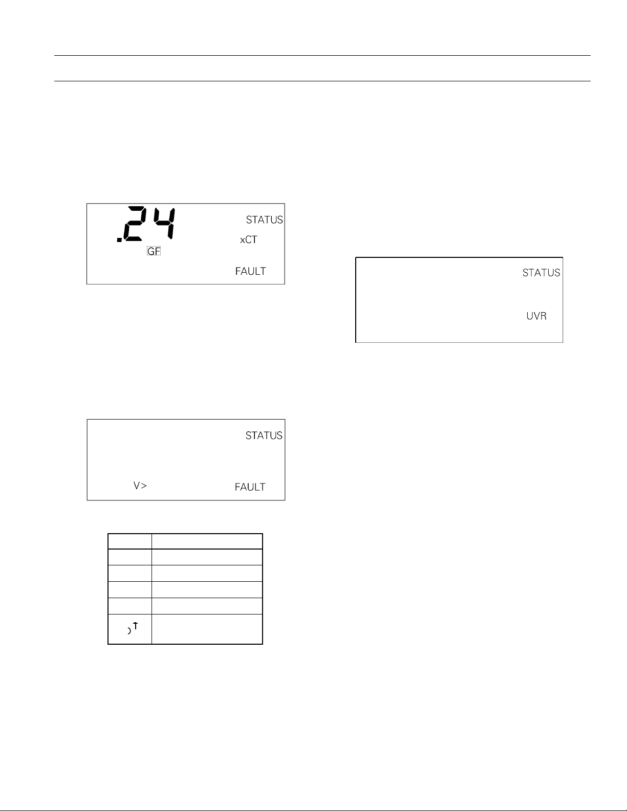
MicroVersaTrip Plus™ and MicroVersaTrip PM™ Trip Units
Chapter 4. Status Mode
Ground-Fault Display
When a ground-fault trip occurs, the display illustrated in Figure 62 appears. The fault current is displayed in units of
xCT
, the breaker CT sensor rating.
Multiply the sensor rating of the breaker by the displayed fault current multiplier to obtain the groundfault current at trip.
Figure 62. Trip Unit status display for ground-fault trip.
Protective-Relay Fault Display
After a protective-relay trip, the display indicates
FAULT with a target for the type of relay that initiated
the trip. This is illustrated in Figure 63 for an
overvoltage trip. The targets for the five protective
relays are listed in Table 18.
Shunt Trip and Undervoltage Release Trip
Displays (RMS9D Series Trip Units Only)
When a Power Break ®II breaker trips due to the
Shunt Trip, Shunt Trip with Lockout, or
Undervoltage Release, the display indicates the trip
with a flashing target, as illustrated in Figure 64. The
indications
ST and UVR appear for Shunt Trip and
Undervoltage Release trips, respectively. Note that
the
FAULT segment does not display, since the trip
originated external to the breaker and may not
represent a true fault condition.
Figure 64. Trip Unit status display for Undervoltage Release
trip.
Clearing the Trip Information
Figure 63. Trip Unit status display for protective-relay trip.
CCCCooooddddeeeePPPPrrrrooootttteeeeccccttttiiiivvvveeee RRRReeeellllaaaayy
∆V Voltage unbalance
∆I Current unbalance
V< Undervoltage
V> Overvoltage
Power reversal
I
I
yy
Table 18. Trip Unit display targets for protective relays.
Since trip information is stored in nonvolatile memory, the Trip Unit continues displaying the trip
information until it is manually cleared or a new trip
occurs. After the trip information has been recorded
or reviewed, it can be cleared with the keypad. With
the Trip Unit in Status mode, hold down the
VALUE
key and press the SELECT key. The trip information is
then cleared and the display reverts to
STATUS OK, as
in Figure 56.
Trip Operations Counter Display
Trip operations counters record the total number of
overcurrent trips. To review any of the trip operations counters while in Status mode, press the
key until the desired count appears. Figure 65
illustrates a typical trip operations counter display.
This example indicates that there have been three
long-time trips on this breaker since the counter was
last reset.
SELECT
31
Page 42

MicroVersaTrip Plus™ and MicroVersaTrip PM™ Trip Units
Chapter 4. Status Mode
Figure 65. Trip Unit status display for long-time overcurrent trip
counter.
Clearing the Trip Operations Counters
Since the trip operations counters are stored in nonvolatile memory, the Trip Unit maintains the information indefinitely. To clear a particular counter,
first display the corresponding count, then hold
down the
trip counter is reset to zero.
VALUE key and press the SELECT key. The
32
Page 43

MicroVersaTrip Plus™ and MicroVersaTrip PM™ Trip Units
Chapter 5. Maintenance and Trouble-Shooting
Rating plugs and MicroVersaTrip Plus and MicroVersaTrip PM Trip Units are factory tested and normally shipped installed in their breaker frame
assemblies or as part of a conversion kit. There is no
requirement for periodic maintenance of the Trip
Units.
within the Trip Units.
There are no user-serviceable components
5-1 Trip Unit Removal and
Replacement
Rejection pins are installed on the rear of all Trip
Units to prevent installation of an incorrect Trip
Unit into a breaker. Do not use excessive force when
installing a Trip Unit. Replacement of a Trip Unit
always requires repeating the setup procedures, as
described in Chapter 2.
Power Break® Insulated-Case Circuit
Breakers
Power Break circuit breakers are shipped from the
factory with their Trip Units installed. Removal is
only necessary for replacement. Refer to GEH-6303
for detailed instructions on replacing Trip Units in
Power Break circuit breakers.
WWWWAAAARRRRNNNNIIIINNNNGGGG::
the breaker off, disconnect it from all voltage
sources, and discharge the closing springs.
AAAAVVVVEEEERRRRTTTTIIIISSSSSSSSEEEEMMMMEEEENNNNTTTT::
procédure, mettre le disjoncteur en position OFF, le
déconnecter de toute tension d’alimentation, et
décharger les ressorts de fermeture.
Power Break II Insulated-Case Circuit
Breakers
Power Break II circuit breakers are shipped from the
factory with their Trip Units installed. Removal is
only necessary for replacement or to change the
accessory-configuration switches.
To remove the Trip Unit, perform the following
procedure:
::
Before beginning this procedure, turn
::
Avant de commencer cette
WWWWAAAARRRRNNNNIIIINNNNGGGG::
the breaker OFF, disconnect it from all voltage
sources, and discharge the closing springs, if they are
charged, by closing and then opening the breaker.
AAAAVVVVEEEERRRRTTTTIIIISSSSSSSSEEEEMMMMEEEENNNNTTTT::
procédure, mettre le disjoncteur en position OFF, le
déconnecter de toute tension d’alimentation, et
décharger les ressorts de fermeture.
1111....Loosen the four #8-32 screws on the breaker
trim-plate assembly and remove the trim plate.
2222....Loosen the four #10-32 screws at the corner of
the breaker cover. Remove the cover from the
breaker face.
3333....Pull the Trip Unit locking lever to the right,
then hold the Trip Unit near the battery cover
and lift it straight out of the breaker.
To reinstall the Trip Unit, perform the following
procedure:
1111....Pull the Trip Unit locking lever to the right.
While holding the lever, carefully align the
connector on the rear of the Trip Unit with the
connector in the breaker. Press down on the
Trip Unit while holding it near the battery
cover. When the Trip Unit is fully seated, slide
the locking lever back to the left.
2222....Reinstall the breaker top cover and tighten the
four #10-32 screws to 32 in-lbs.
3333....Replace the trim plate and tighten the four
#8-32 screws to 20 in-lbs.
::
Before beginning this procedure, turn
::
Avant de commencer cette
Type AKR Low-Voltage Power Circuit
Breakers
Type AKR circuit breakers are shipped from the factory with their Trip Units installed. Removal is necessary only for replacement. Trip Units are separately
mounted on the breaker structure and are removed
by moving the Trip Unit removal bracket. When a
Trip Unit is replaced, the locking arm snaps back
into place to indicate proper engagement. Refer to
GEH-6303 for detailed instructions on replacing
Trip Units in in Type AKR circuit breakers.
33
Page 44

MicroVersaTrip Plus™ and MicroVersaTrip PM™ Trip Units
Chapter 5. Maintenance and Trouble-Shooting
WWWWAAAARRRRNNNNIIIINNNNGGGG::
breakers before attempting to remove or replace the
Trip Unit. Because of the exposed location of the
Trip Unit, failure to observe this warning may result
in equipment damage or personal injury, including
death.
AAAATTTTTTTTEEEENNNNTTTTIIIIOOOONNNN::
AKR de toute tension avant d’enlever ou remplacer
le déclencheur. L’emplacement du déclencheur
étant proche de parties sous tension, le non respect
de cet avertissement peut entrainer des
endommagements du matériel, et des blessures
pouvant être mortelles.
::
Always de-energize Type AKR circuit
::
Deconneter le disjoncteur de type
5-2 Rating Plug Removal and
Replacement
CCCCAAAAUUUUTTTTIIIIOOOONNNN::
breaker is carrying current reduces the breaker’s
current-carrying capacity to approximately 25% of
the current sensor rating.
AAAATTTTTTTTEEEENNNNTTTTIIIIOOOONNNN::
et traversé par un courant, le niveau de protection
s’ajuste à approximativement 25% du calibre du
transformateur d’intensité.
Interchangeable rating plugs are removed with a
Rating Plug Extractor, Catalog No. TRTOOL.
(Suitable equivalents are commercially available as
“integrated circuit (DIP) extractors.”) Grasp the rating plug tabs with the extractor and pull the plug out
as illustrated in Figure 66. Be sure to grab the tabs
and not the front cover of the rating plug, or the
plug may be damaged.
::
Removal of the rating plug while the
::
Si le calibreur est retiré le disjoncteur
Figure 66. Removing the interchangeable rating plug.
Rejection features are provided on all rating plugs to
prevent application mismatches. Never force a rating
plug into place. Refer to Chapter 1 to find the
appropriate rating plugs for each sensor rating and
breaker frame.
If a replacement rating plug has a different rating
than the plug that was removed, follow the appropriate setup procedure in Chapter 2 to enter the new
rating.
Do not attempt to use a rating plug from a Spectra
RMS™ breaker or a MicroVersaTrip RMS-9/MVT-4
function trip in a MicroVersaTrip Plus or MicroVersaTrip PM Trip Unit.
5-3 Trouble-Shooting Guide
The following guide is provided for trouble-shooting
and isolating common problems. It does not cover
every possible condition. Contact the Customer
Support Center at 800-843-3742 if the problem is not
resolved by these procedures.
34
Page 45

MicroVersaTrip Plus™ and MicroVersaTrip PM™ Trip Units
Chapter 5. Maintenance and Trouble-Shooting
SSSSyyyymmmmppppttttoooomm
1. The Trip Unit display is
2. The Trip Unit display
3. The Trip Unit display
4. The trip indication
5. Unit does not com-
mm
blank.
flashes.
flashes ERR.
target will not clear.
municate with the
Monitor, POWER
LEADER Distribution
Software, or FPU.
PPPPoooossssssssiiiibbbblllleeee CCCCaaaauuuussssee
Line current is below 20% of
the breaker sensor rating
(MicroVersaTrip Plus).
External +24 Vdc is absent
(MicroVersaTrip PM).
Can occur on Plus-style Trip
Units when the load current
fluctuates near 20% of the
breaker sensor rating.
The built-in self test has
detected an error.
Trip Unit is not in Status
mode.
The commnet wires are
shorted or improperly
connected.
FPU version is lower than 2.0.
The Trip Unit address is
incorrect.
ee
CCCCoooorrrrrrrreeeeccccttttiiiivvvveeee AAAAccccttttiiiioooonn
At least 20% of the current sensor rating,
be flowing through the breaker to activate the display.
If not, power the Trip Unit with the internal battery
or the Portable Power Pack. The battery power supply
is disabled when any current is sensed through the
current sensors.
Check that the control power supply is present and
operational.
Power the Trip Unit with the internal battery or the
Portable Power Pack.
Replace the Trip Unit.
Press FUNCTION until STATUS is displayed. Hold
down the VALUE key and press the SELECT key to
clear the target.
Locate and repair the short or the incorrect connection.
Update the FPU to version 2.0 or higher.
Check that the address assigned to the Trip Unit, as
in Chapter 2, agrees with the address at the host.
nn
xCT
, must
6. Current readings are
incorrect.
7. Voltage readings are
incorrect.
8. The display is blank or
the Low Battery symbol
appears when the
BATTERY key is pressed.
The rating plug value was
defined incorrectly.
The potential transformer
(PT) primary voltage was
defined incorrectly.
The PT connection was
defined incorrectly.
The battery is discharged.
The battery was stored too
long with no power applied to
the Trip Unit
35
Read the X value from the rating plug name plate
and enter this as the
current set point procedure in Chapter 2.
xIn
value with the rating plug
Do not
enter the sensor rating, S.
Read the PT primary rating from the PT name plate
and enter this value with the PT primary voltage
procedure in Chapter 2.
Follow the PT connection procedure in Chapter 2 to
enter Ph-N for a wye-connected PT primary or Ph-Ph
for a delta-connected PT.
Replace the battery.
Power the Trip Unit with external power or by
energizing the breaker for several days to freshen the
battery.
Page 46

MicroVersaTrip Plus™ and MicroVersaTrip PM™ Trip Units
Appendix 1
Catalog Numbers for RMS9C Trip
Units in AKR Circuit Breakers
The following table contains the catalog number
options for AKR circuit breakers, with an illustration
of a valid number and the options that each part of
the number refers to.
AAAA 22
22
00004444 LLLL SSSS IIII GGGG ZZZZ1111 PPPP MMMM RR
RR
CCCCooooddddeeeeDDDDeeeessssccccrrrriiiippppttttiiiioooonn
A AKR BBBBrrrreeeeaaaakkkkeeeerrrr TTTTyyyyppppee
225–2000 A maximum CT
2
3200 A maximum CT
3
4000 A maximum CT
4
150 A
01
225 A
03
400 A
04
600 A
06
800 A
08
1600 A
16
2000 A
20
3000 A
30
3200 A
32
4000 A
40
Long-time (standard)
L
Short-time
S
High instantaneous
H
Instantaneous
I
Fixed high instantaneous
K
Ground fault
G
Defeatable ground fault (not UL listed)
GD
W curve
W
Ground-fault zone-selective interlock
Z1
Ground-fault and short-time ZSI
Z2
Switchable instantaneous short time and ground fault
X
PMRelaying and communication
Metering and communication
R Replacement trip unit RRRReeeeppppllllaaaacccceeeemmmmeeeennnntt
nn
FFFFuuuunnnnccccttttiiiioooonn
BBBBrrrreeeeaaaakkkkeeeerrrr FFFFrrrraaaammmmee
((((mmmmaaaaxxxx CCCCTTTT))
IIIInnnnssssttttaaaalllllllleeeedddd CCCCTT
OOOOvvvveeeerrrrccccuuuurrrrrrrreeeennnntttt PPPPrrrrooootttteeeeccccttttiiiioooonn
GGGGrrrroooouuuunnnndddd----FFFFaaaauuuulllltt
PPPPrrrrooootttteeeeccccttttiiiioooonn
OOOOppppttttiiiioooonnnnaaaallll FFFFuuuunnnnccccttttiiiioooonnnnss
CCCCoooommmmmmmmuuuunnnniiiiccccaaaattttiiiioooonnnn,,
MMMMeeeetttteeeerrrriiiinnnngggg,,,, &&&& RRRReeeellllaaaayyyyiiiinnnngg
nn
ee
ee
))
TT
nn
tt
nn
ss
,,
gg
tt
36
Page 47

MicroVersaTrip Plus™ and MicroVersaTrip PM™ Trip Units
Catalog Numbers for RMS9C Trip
Units in Power Break
The following table contains the catalog number
options for Power Break circuit breakers, with an
illustration of a valid number and the options that
each part of the number refers to.
® Circuit Breakers
Appendix 2
CCCC 22
22
00008888 LLLL SSSS IIII GGGG ZZZZ1111 PPPP MMMM RR
RR
CCCCooooddddeeeeDDDDeeeessssccccrrrriiiippppttttiiiioooonn
C Power Break BBBBrrrreeeeaaaakkkkeeeerrrr TTTTyyyyppppee
800–2000 A maximum CT
2
3000 A maximum CT
3
4000 A maximum CT
4
200 A
02
400 A
04
800 A
08
1000 A
10
1600 A
16
2000 A
20
2500 A
25
3000 A
30
4000 A
40
Long-time (standard)
L
Short-time
S
High instantaneous
H
Instantaneous
I
GGDGround fault
Defeatable ground fault (not UL listed)
Z1Z2Ground-fault zone-selective interlock
Ground-fault and short-time ZSI
PMRelaying and communication
Metering and communication
R Replacement trip unit RRRReeeeppppllllaaaacccceeeemmmmeeeennnntt
nn
FFFFuuuunnnnccccttttiiiioooonn
BBBBrrrreeeeaaaakkkkeeeerrrr FFFFrrrraaaammmmee
((((mmmmaaaaxxxx CCCCTTTT))
IIIInnnnssssttttaaaalllllllleeeedddd CCCCTT
OOOOvvvveeeerrrrccccuuuurrrrrrrreeeennnntttt PPPPrrrrooootttteeeeccccttttiiiioooonn
GGGGrrrroooouuuunnnndddd----FFFFaaaauuuulllltt
PPPPrrrrooootttteeeeccccttttiiiioooonn
OOOOppppttttiiiioooonnnnaaaallll FFFFuuuunnnnccccttttiiiioooonnnnss
CCCCoooommmmmmmmuuuunnnniiiiccccaaaattttiiiioooonnnn,,
MMMMeeeetttteeeerrrriiiinnnngggg,,,, &&&& RRRReeeellllaaaayyyyiiiinnnngg
nn
ee
ee
))
TT
nn
tt
nn
ss
,,
gg
tt
37
Page 48
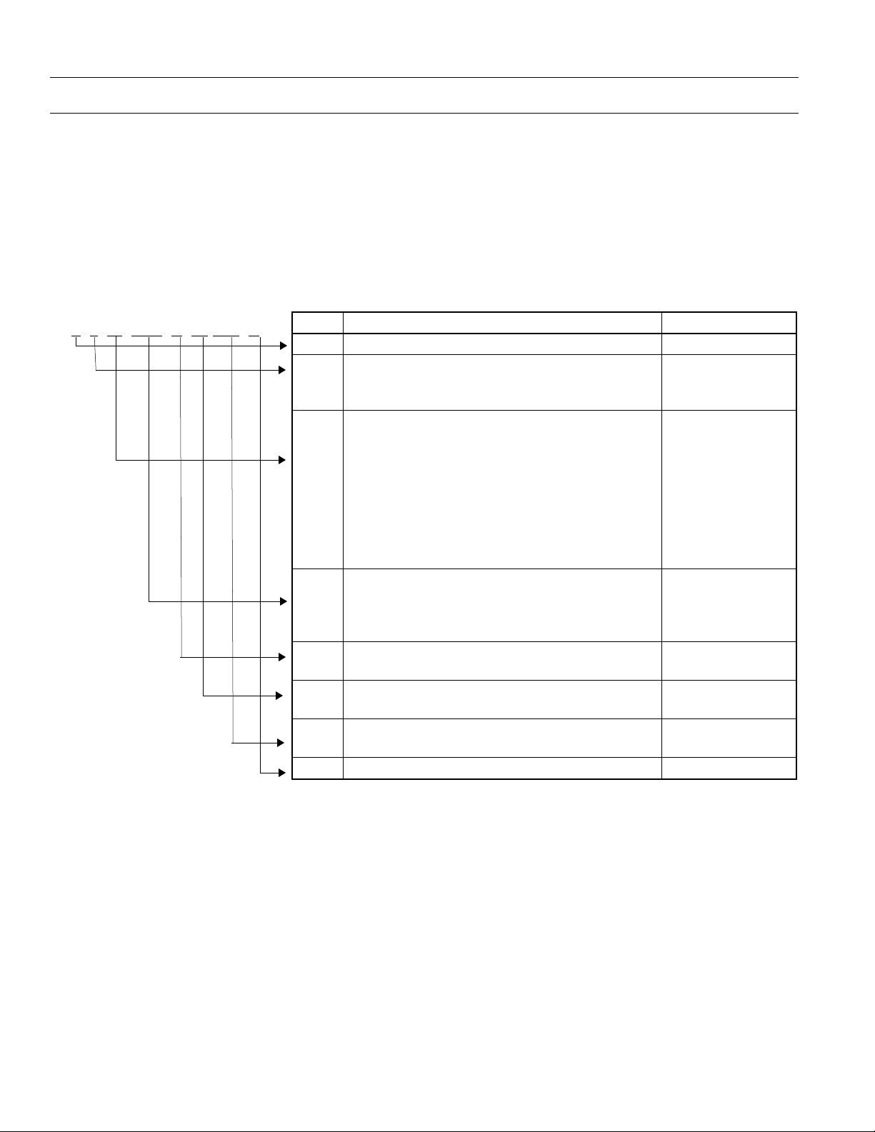
MicroVersaTrip Plus™ and MicroVersaTrip PM™ Trip Units
Appendix 3
Catalog Numbers for RMS9D Trip
Units in Power Break
Breakers
The following table contains the catalog number
options for Power Break II circuit breakers, with an
illustration of a valid number and the options that
each part of the number refers to.
® II Circuit
BBBB 22
22
00008888 LLLL SSSS IIII GGGG ZZZZ1111 PPPP MMMM RR
RR
CCCCooooddddeeeeDDDDeeeessssccccrrrriiiippppttttiiiioooonn
B Power Break II BBBBrrrreeeeaaaakkkkeeeerrrr TTTTyyyyppppee
2000 A maximum CT
2
3000/3200 A maximum CT
3
4000 A maximum CT
4
200 A
02
400 A
04
800 A
08
1000 A
10
1600 A
16
2000 A
20
2500 A
25
3000 A
30
4000 A
40
Long-time (standard)
L
Short-time
S
High instantaneous
H
Instantaneous
I
GGDGround fault
Defeatable ground fault (not UL listed)
Z1Z2Ground-fault zone-selective interlock
Ground-fault and short-time ZSI
PMRelaying and communication
Metering and communication
R Replacement trip unit RRRReeeeppppllllaaaacccceeeemmmmeeeennnntt
nn
FFFFuuuunnnnccccttttiiiioooonn
BBBBrrrreeeeaaaakkkkeeeerrrr FFFFrrrraaaammmmee
((((mmmmaaaaxxxx CCCCTTTT))
IIIInnnnssssttttaaaalllllllleeeedddd CCCCTT
OOOOvvvveeeerrrrccccuuuurrrrrrrreeeennnntttt PPPPrrrrooootttteeeeccccttttiiiioooonn
GGGGrrrroooouuuunnnndddd----FFFFaaaauuuulllltt
PPPPrrrrooootttteeeeccccttttiiiioooonn
OOOOppppttttiiiioooonnnnaaaallll FFFFuuuunnnnccccttttiiiioooonnnnss
CCCCoooommmmmmmmuuuunnnniiiiccccaaaattttiiiioooonnnn,,
MMMMeeeetttteeeerrrriiiinnnngggg,,,, &&&& RRRReeeellllaaaayyyyiiiinnnngg
nn
ee
ee
))
TT
nn
tt
nn
ss
,,
gg
tt
38
Page 49

MicroVersaTrip Plus™ and MicroVersaTrip PM™ Trip Units
Trip Unit Battery Suppliers
CCCCaaaattttaaaalllloooogg
SSSSuuuupppppppplllliiiieeeerr
Wilson Greatbatch Ltd.
Electrochem Lithium Batteries
10,000 Wehrle Drive
Clarence, NY
(716) 759–5428
Contact the supplier for the nearest distributor.
rr
NNNNuuuummmmbbbbeeeerr
3B24–XA
Appendix 4
gg
rr
39
Page 50

Page 51

Page 52

g
General Electric Company
41 Woodford Ave., Plainville, CT 06062
GEH6273 R06 1299 © 1999 General Electric Company
GE Electrical Distribution & Control
 Loading...