

Page 1
GE Consumer & Industrial
ASTAT XT
User Manual
Page 2
2 •Warnings
WARNINGS
1. DISCONNECT POWER BEFORE INSTALLING OR SERVICING.
2. HAZARDOUS VOLTAGES ARE PRESENT IN THE MOTOR CIRCUIT EVEN WHEN THE STARTER IS OFF. AN
ISOLATION CONTACTOR IS RECOMMENDED, CONFIGURED TO PROVIDE AUTOMATIC ISOLATION WHEN
THE MOTOR IS TURNED OFF.
3. UNIT MAY CONTAIN MORE THAN ONE LIVE CIRCUIT. DISCONNECT BOTH CONTROL AND MAIN CIRCUITS
BEFORE INSTALLING OR SERVICING.
4. SOFT STOP SHOULD NOT BE USED AS AN EMERGENCY STOP.
5. STOPPING MODE MUST BE SET TO MEET APPLICABLE STANDARDS FOR OPERATOR SAFETY.
6. SEPARATE MOTOR OVERCURRENT PROTECTION IS REQUIRED TO BE PROVIDED IN ACCORDANCE WITH
THE CANADIAN ELECTRICAL CODE, PART 1. ASTAT-XT PROVIDES SEPARATE MOTOR PROTECTION.
CAUTIONS
1. SEMI-CONDUCTOR FUSES SPECIFIED MAY NOT PROVIDE BRANCH CIRCUIT PROTECTION. REFER TO
LOCAL APPLICABLE ELECTRICAL CODES.
2. OVERLOAD RELAY SETTING SHOULD BE PROPERLY COORDINATED WITH MOTOR.
3. SLOW SPEED RUNNING WILL AFFECT THE MOTOR THERMAL CHARACTERISTIC DUE TO REDUCED
COOLING.
CARE MUST BE TAKEN WHEN OPERATING MOTOR UNDER THESE CONDITIONS.
4. ABNORMAL STARTING TIMES IN EXCESS OF 30 SECONDS, OR CLOSELY REPEATED OPERATIONS OF
ACCELERATION RAMP/DECELERATION RAMP, SLOW SPEED, MAY CAUSE MOTOR DAMAGE. CONTACT
MOTOR MANUFACTURER FOR PROPER MOTOR SELECTION.
5. IF CONTROL POWER IS LOST BETWEEN STARTS, THE OVERLOAD RELAY PROTECTION IS RESET TO COLD
START CONDITIONS.
REMARKS:
1. Read this manual thoroughly before using the ASTAT-XT and store in a safe place for reference.
2. Make sure that this manual is delivered to the end user.
3. The policy of GE Industrial Systems is one of continuous improvement.
The right is reserved to alter the design on any structural details of the products at any time without giving notice.
Page 3

3 • Table of Contents
ASTAT-XT User Manual
1.
Generalities..................................................................................................................................................... 7
1.1 Squirrel-Cage Motor Starting.................................................................................................................................................... 7
1.2 Advantages of the ASTAT-XT Solid State Soft Starters ................................................................................................. 7
2. Types and Ratings ......................................................................................................................................... 8
2.1 IEC Ratings. Recommended Motor and Type Unit Ratings........................................................................................ 8
2.2 NEMA Ratings . Recommended Motor and Type Unit Ratings................................................................................. 9
2.3 Thermal Characteristics ............................................................................................................................................................10
3. Technical Specifications .............................................................................................................................11
3.1 General Specifications ...............................................................................................................................................................11
3.2 Weight................................................................................................................................................................................................13
3.3 I/O Terminal Board Specifications........................................................................................................................................13
3.4 I/O Wiring..........................................................................................................................................................................................17
3.5 Ordering Information..................................................................................................................................................................18
3.5.1 Ordering Accessories .................................................................................................................................................18
3.6 Operating Modes ..........................................................................................................................................................................19
4. Control Keypad.............................................................................................................................................20
4.1 LCD Arrangement.........................................................................................................................................................................20
4.2 Push-Buttons..................................................................................................................................................................................21
4.3 Status LEDs......................................................................................................................................................................................21
4.4 Reviewing and Modifying Parameters...............................................................................................................................21
4.5 Special Actions Performed in Test/Maintenance Mode .............................................................................................22
4.5.1 Run Self Test ...................................................................................................................................................................22
4.5.2 View Software Version...............................................................................................................................................22
4.5.3 Obtain Default Parameters ..................................................................................................................................... 22
4.5.4 Reset Statistical Data .................................................................................................................................................22
4.5.5 Calibrate Voltage and Current (Factory Use Only!) .....................................................................................23
4.6 Mode Pages.....................................................................................................................................................................................23
4.7 Overview of All Mode Pages and Factory Defaults......................................................................................................24
4.7.1 Display Mode – Page 0 ..............................................................................................................................................26
4.7.2 Main Settings – Page 1 ..............................................................................................................................................27
4.7.3 Start Settings – Page 2 ..............................................................................................................................................29
4.7.3.1 Soft Start Parameters.......................................................................................................................................32
4.7.4 Stop Settings – Page 3 ...............................................................................................................................................34
4.7.4.1 Soft Stop Parameters ....................................................................................................................................... 35
4.7.5 DUAL Settings Parameters – Page 4...................................................................................................................36
4.7.6 Slow Speed & Energy Save Parameters – page 5........................................................................................37
4.7.7 Fault Settings – Page 6 ..............................................................................................................................................38
4.7.8 I/O Settings Parameters – Page 7........................................................................................................................ 40
4.7.8.1 Terminal 7 and 8 Programming ..................................................................................................................41
4.7.9 COMM. Parameters – Page 8 – With the Modbus standard PCB ..........................................................42
4.7.10 Comm. Parameters – Page 8 – With the Profibus optional PCB............................................................42
4.7.11 Comm. Parameters – Page 8 – With the DeviceNet Optional PCB ......................................................43
4.7.12 Statistical Data – page 9...........................................................................................................................................44
4.8 Non Adjustable Protection and Fault Reset.....................................................................................................................45
4.8.1 Under/Over Frequency .............................................................................................................................................45
4.8.2 Phase Loss.......................................................................................................................................................................45
4.8.3 Phase Sequence ...........................................................................................................................................................45
4.8.4 Wrong Connection ......................................................................................................................................................45
4.8.5 Shorted SCR ....................................................................................................................................................................45
4.8.6 Heat-Sink Over Temperature .................................................................................................................................45
4.8.7 External Fault .................................................................................................................................................................45
4.8.8 Fault and Reset .............................................................................................................................................................45
4.8.9 Auto Reset........................................................................................................................................................................46
4.9 Timing Occurrence Table..........................................................................................................................................................46
Page 4

4 • Table of Contents
5. Installation .................................................................................................................................................... 47
5.1 Prior to Installation.......................................................................................................................................................................47
5.2 Mounting...........................................................................................................................................................................................47
5.3 Temperature Range & Heat Dissipation............................................................................................................................47
5.3.1 Forced Ventilation........................................................................................................................................................48
5.4 Main PCB and Optional PCBs..................................................................................................................................................48
5.5 Dip Switch Settings on the Main PCB..................................................................................................................................49
5.5.1 Switch # 1 – Display Modes ....................................................................................................................................49
5.5.2 Switch # 2 – Not used ................................................................................................................................................50
5.5.3 Switch # 3 – Main/ D.Set: Generator Parameters.........................................................................................50
5.5.4 Switches # 5, 6 – Language Selection................................................................................................................50
5.5.5 Switch # 7 – Expanded Settings............................................................................................................................ 50
5.5.6 Switch # 8 – Software Lock .....................................................................................................................................50
5.6 Internal Fan Control ....................................................................................................................................................................51
5.7 Analog I/O (Terminals T1, T2, Gnd, Out (-), Out (+)) ........................................................................................................51
5.8 Remote Key-Pad Installation..................................................................................................................................................52
6. Starting Procedure ...................................................................................................................................... 53
6.1 Standard Starting Procedure..................................................................................................................................................54
Examples of Starting Curves...................................................................................................................................................55
6.2
6.2.1 Light Loads - Pumps, Etc. .........................................................................................................................................55
6.2.2 High Inertia Loads: Crushers, Centrifuges, Mixers, Etc...............................................................................55
6.2.3 Special Starting Using DUAL Settings ................................................................................................................56
6.2.3.1 Special Starting – Using DUAL Settings – Wiring Diagram ............................................................57
6.2.4 Choosing a Suitable Pump Curve (Centrifugal Pumps)..............................................................................57
6.2.4.1 Starting Curve ......................................................................................................................................................57
6.2.4.2 Stopping Curve ....................................................................................................................................................58
6.2.4.3 End Torque During Soft-Stopping a Pump Motor...............................................................................58
7. Trouble Shooting.......................................................................................................................................... 59
8. Application diagrams.................................................................................................................................. 62
8.1 Terminal 21 Connections With Various Mains................................................................................................................62
8.2 Control Supply, Control Input and Mains are From the Same Source, Neutral Connected to Terminal 21
63
8.3 Control Supply and Control Input From the Same Source, Neutral not Connected to Terminal 21 ....63
8.4 Control Supply and Control Input from Separate Sources ......................................................................................64
8.5 Soft Start, Soft Stop and Stop, Control Supply and Control Input from the Same Source........................64
8.6 Soft Start, Soft Stop and Stop, Control Supply and Control Input from Separate Sources ......................64
8.7 Soft Start and Immediate Stop (no Soft Stop) .................................................................................................................65
8.8 Soft Start and Soft Stop .............................................................................................................................................................65
8.9 Soft Start, Soft Stop and Immediate Stop.........................................................................................................................65
8.10 Energy Save, Slow Speed or Reset.................................................................................................................................66
8.11 Slow Speed and Slow Speed Reverse ...........................................................................................................................66
8.12 External Fault............................................................................................................................................................................67
8.13 Line Contactor..........................................................................................................................................................................67
8.14 Bypass Contactor...................................................................................................................................................................68
8.15 Reversing with Two Line Contactors .............................................................................................................................69
8.16 Operating via Communication Links.............................................................................................................................70
8.17 D.Set: Generator Parameters Wiring.............................................................................................................................71
8.18 Short Circuit Protection........................................................................................................................................................72
8.19 Transient Protection ..............................................................................................................................................................73
8.20 Inside Delta Configuration..................................................................................................................................................74
8.18.1 Type 1 Coordination ................................................................................................................................................... 72
8.18.1.1 Type 1 Coordination with GE Circuit Breakers: ....................................................................................72
8.18.1.2 Type 1 Coordination with Type aM Siba Fuses:................................................................................... 72
8.18.2 Type 2 Coordination ................................................................................................................................................... 72
8.20.1 General Information ...................................................................................................................................................74
8.20.2 Notes on Inside Delta Connection .......................................................................................................................74
8.20.3 Motor Connection and Terminals......................................................................................................................... 75
Page 5

5 • Table of Contents
8.20.4 ASTAT-XT Connected Inside Delta w/Bypass Contactor and Inside Delta Contactor ................76
8.20.5 ASTAT-XT Connected Inside Delta - Reverse Speed....................................................................................77
9. Dimensions....................................................................................................................................................78
9.1 UL cUL Approved Models..........................................................................................................................................................78
9.2 Non UL cUL Approved Models................................................................................................................................................82
Appendix A - MODBUS RTU Protocol......................................................................................................................86
A.1. Introduction.....................................................................................................................................................................................86
A.2. Basic Structure of the Serial Link Frame ...........................................................................................................................87
A.3. SYNC (Silent Interval) ...................................................................................................................................................................87
A.4. Serial Link No. (Slave Address)...............................................................................................................................................87
A.5. Function ............................................................................................................................................................................................87
A.6. List of Functions Supported By The ASTAT-XT ...............................................................................................................87
A.7. Actual Data (3X References & 4X References)................................................................................................................89
A.8. Parameter Settings (4X References) ....................................................................................................................................91
A.9. Control Register Write (4X Reference) ................................................................................................................................94
A.10. Discrete Commands (Coils, 0x References)...............................................................................................................95
A.11. Discrete Hardwired Inputs (1x References)...............................................................................................................97
A.12. Diagnostics ................................................................................................................................................................................98
A.13. Exception Responses ............................................................................................................................................................99
Appendix B - Profibus..............................................................................................................................................101
B.1. Operation Mode in PROFIBUS:.............................................................................................................................................101
B.1.1. Structure of the ASTAT-XT Receiving Frame ................................................................................................ 101
B.1.2. Structure of the ASTAT-XT Transmitting Frame ......................................................................................... 101
B.1.2.1. Selection of the DPV0 Registers through Data Request (DPV1)................................................ 101
B.1.3. Read and Write from Random Registers via Data Request .................................................................102
B.2. Configure the PROFIBUS in the ASTAT-XT......................................................................................................................103
B.3. Watch Dog Definition ..............................................................................................................................................................103
B.4. Actual Data Register Numbers (decimal) ....................................................................................................................... 104
B.5. Setting Parameters Registers for Data Request......................................................................................................... 106
Appendix C - DeviceNet™ to Modbus™ Gateway..............................................................................................108
C.1. Introduction.................................................................................................................................................................................. 108
C.1.1. Overview........................................................................................................................................................................ 108
C.1.2. Definitions..................................................................................................................................................................... 108
C.1.3. Reference Documents............................................................................................................................................ 108
C.1.4. Open DeviceNet Vendor Association, Inc. (ODVA) ..................................................................................... 108
C.1.5. Rotary Switch Configuration ............................................................................................................................... 109
C.1.6. LED Indicators............................................................................................................................................................. 109
C.2. Identity Object (01
1 Instance) ..................................................................................................................................... 111
HEX -
C.2.1. Class Attributes (Instance 0)................................................................................................................................. 111
C.2.2. Instance Attributes (Instance 1) ......................................................................................................................... 111
C.2.3. Common Services..................................................................................................................................................... 111
C.3. Message Router Object (02
C.4. DeviceNet Object (03
HEX -
1 Instance) ...................................................................................................................111
HEX -
1 Instance)................................................................................................................................111
C.4.1. Class Attributes (Instance 0)................................................................................................................................. 111
C.4.2. Instance Attributes (Instance 1) ......................................................................................................................... 111
C.4.3. Common Services..................................................................................................................................................... 111
C.5. Assembly Object (04
– 4 Instances) ............................................................................................................................112
HEX
C.5.1. Class Attributes (Instance 0)................................................................................................................................. 112
C.5.2. Output (O2T) Instance Attributes – Register 40752 .................................................................................. 112
C.5.2.1. Output Instance 112 (0x70) – Control Output.................................................................................... 112
C.5.3. Input (T20) Instance Attributes – Register 40257....................................................................................... 112
C.5.3.1. Input Instance 60 (0x3C) – Basic Softstart Input .............................................................................. 112
C.5.3.2. Input Instance 61 (0x3D) – Extended Softstart Input ..................................................................... 112
C.5.3.3. Input Instance 100 (0x64) – Status .........................................................................................................112
C.5.4. Common Services..................................................................................................................................................... 113
C.6. Connection Object (05
2 Instances) ..........................................................................................................................113
HEX –
Page 6

C.6.1. Class Attributes (Instance 0)................................................................................................................................. 113
C.6.2. Instance Attributes (Instances 1-2) Explicit, Polled I/O............................................................................ 113
C.6.3. Common Services..................................................................................................................................................... 115
C.7. Softstart Object (2D
1 Instance)...................................................................................................................................115
HEX -
C.7.1. Class Attributes (Instance 0)................................................................................................................................. 115
C.7.2. Instance Attributes (Instance 1) ......................................................................................................................... 115
C.7.2.1. Extended AtReference Values................................................................................................................... 115
C.7.2.2. Extended StartMode Values....................................................................................................................... 115
C.7.3. Common Services..................................................................................................................................................... 115
C.8. Control Supervisor Object (29
1 Instances)............................................................................................................ 115
HEX -
C.8.1. Class Attributes (Instance 0)................................................................................................................................. 115
C.8.2. Instance Attributes (Instance 1) ......................................................................................................................... 115
C.8.3. Common Services..................................................................................................................................................... 116
C.9. Modbus / Serial Object (65
1 Instance).................................................................................................................... 116
HEX –
C.9.1. Class Attributes (Instance 0)................................................................................................................................. 116
C.9.2. Instance Attributes (Instance 1) ......................................................................................................................... 116
C.9.3. Common Services..................................................................................................................................................... 117
C.10. Input Object (70
1 Instance) ....................................................................................................................................117
HEX –
C.10.1. Class Attributes (Instance 0) ............................................................................................................. 117
C.10.2. Instance Attributes (Instance 1) ...................................................................................................... 117
C.10.3. Common Services.................................................................................................................................. 118
C.11. Main Parameter Object (71
1 Instance)............................................................................................................. 118
HEX –
C.11.1. Class Attributes (Instance 0) ............................................................................................................. 118
C.11.2. Instance Attributes (Instance 1) ...................................................................................................... 118
C.11.3. Common Services.................................................................................................................................. 119
C.12. Start Settings Object (72
1 Instance)................................................................................................................... 119
HEX –
C.12.1. Class Attributes (Instance 0) ............................................................................................................. 119
C.12.2. Instance Attributes (Instance 1) ...................................................................................................... 119
C.12.3. Common Services.................................................................................................................................. 119
C.13. Stop Settings Object (73
1 Instance) ...................................................................................................................119
HEX –
C.13.1. Class Attributes (Instance 0) ............................................................................................................. 119
C.13.2. Instance Attributes (Instance 1) ...................................................................................................... 119
C.13.3. Common Services.................................................................................................................................. 119
C.14. Dual Settings Object (74
1 Instance)................................................................................................................... 119
HEX –
C.14.1. Class Attributes (Instance 0) ............................................................................................................. 119
C.14.2. Instance Attributes (Instance 1) ...................................................................................................... 120
C.14.3. Common Services.................................................................................................................................. 120
C.15. Slow SP & Saving Parameters Object (75
C.15.1. Class Attributes (Instance 0) ............................................................................................................. 120
C.15.2. Instance Attributes (Instance 1) ...................................................................................................... 120
C.15.3. Common Services.................................................................................................................................. 120
C.16. Fault Settings Object (76
1 Instance) ..................................................................................................................120
HEX –
C.16.1. Class Attributes (Instance 0) ............................................................................................................. 120
C.16.2. Instance Attributes (Instance 1) ...................................................................................................... 120
C.16.3. Common Services.................................................................................................................................. 121
C.17. I/O Settings Object (77
1 Instance) ......................................................................................................................121
HEX –
C.17.1. Class Attributes (Instance 0) ............................................................................................................. 121
C.17.2. Instance Attributes (Instance 1) ...................................................................................................... 121
C.17.3. Common Services.................................................................................................................................. 121
C.18. Communication Parameter Object (78
C.18.1. Class Attributes (Instance 0) ............................................................................................................. 121
C.18.2. Instance Attributes (Instance 1) ...................................................................................................... 121
C.18.3. Common Services.................................................................................................................................. 122
6 • Table of Contents
1 Instance)................................................................................. 120
HEX –
1 Instance) .....................................................................................121
HEX –
Page 7

1. GENERALITIES
1.1 Squirrel-Cage Motor Starting
7 • Generalities
There a
re numerous applications where soft starting and limited current peak are needed, thereby making direct
starting of squirrel-cage motors impossible. Traditionally in such cases other types of starting with reduced stator
voltage have been resorted to. The best-known are star-delta starters, autotransformer starters, stator resistance
starters or using part winding motors.
Any reduced starting voltage imposes a current limitation, thus reducing the starting torque, but there will always
be peaks during the change from one point or state to another which can damage the machine being driven.
Note that in general, all reduced voltage starts reduce torque in squared proportion to the current in the phases of
the motor (not on the line) and the latter in turn is reduced in linear proportion to the voltage. From this it can be
deduced that any start with reduced voltage reduces the torque in squared proportion to the voltage per motor
phase. From this point of view soft starting produces just like any other reduced voltage start, a reduction in starting
torque, according to the adjusted parameters. The advantage is the ease with which this ramp can be controlled to
produce a soft start in accordance with the actual requirement of the machine.
1.2 Advantages of the ASTAT-XT Solid State Soft Starters
Increase in productivity and reliability with the use of static soft
starters
Starting and stopping the motor without steps or transitions lengthens the life
of power-driven machine mechanical elements, greatly reducing stress on
transmission and coupling parts.
Consequently, overhauling times are reduced and machine and facility
lifespans are lengthened.
Improvement in acceleration / deceleration characteristics
Being able to start by using the voltage ramp or alternatively by limiting
current lets acceleration fit the load characteristics. Application of a pulse
start may also be selected in cases of high static friction load.
Stopping may be made by cutting-off power or by soft stop ramp.
Protected motor
The soft starter protects the motor from overloads as well as from incorrect
operating conditions such as loss of an input or output phase, blocked rotor,
thyristor short circuit, etc.
Digital technology
The control system is based on the use of a highly specialized microcontroller
by which signals are treated digitally, thereby avoiding deratings and
adjustments common to analogue circuits and obtaining excellent precision
and speed of execution.
The control board is made with the technology of surface mounting devices
(SMD), which increases equipment reliability.
Easy to run and adjust
This unit can be used for a wide range of applications.
Adjustments are very easy to make and diverse options maybe selected for
have equipment capabilities suited to application needs every time.
Easy maintenance due to full monitoring
The alphanumeric display and the LEDs on its front overlay makes the
equipment working conditions known at any time.
Pump control
The ASTAT-XT includes several soft stop curves which is more effective than
the standard soft stop, reducing fluid surges or hammering in a pipe line
system. This method reduces the motor speed, by controlling internal
parameters in the motor as well as the output voltage in a close-loop system.
Advanced functions
The ASTAT-XT includes advanced functions, like linear acceleration ramp,
forward and reverse jog, programmable I/O or connection to a control system
via Modbus protocol included as standard and other optional protocols.
These functions allow the incorporation of the soft starter to a distributed
control net, in automated plant processes, together with other soft starters,
programmable controllers, variable speed drives, etc.
High level of immunity
Design of the unit was closely tied to the conditions of supply lines, which
handle more disturbances every day. The control signals are
opto-electronically isolated and various levels of protection have been set up
in the circuits to immunize the equipment against external disturbance and its
effects.
Page 8
8 • Types and Ratings
2. TYPES AND RATINGS
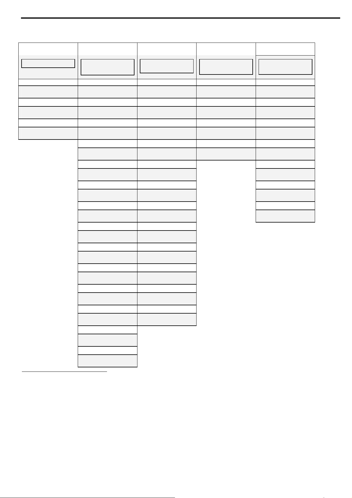
2.1 IEC Ratings
1
. Recommended Motor and Type Unit Ratings.
Light
Duty
Max
Current
Rating
17 17 4 7.5 7.5 15 15 12 3 5.5 5.5 10 8 QTx0017Uxxxx
34 31 8 15 18.5 15 22 31 8 15 18.5 25 22 QTx0031Uxxxx
54 44 11 22 30 40 37 44 11 22 30 40 37 QTx0044Uxxxx
65 58 15 30 37 50 55 55 15 30 37 50 45 QTx0058Uxxxx
72 72 22 37 45 60 55 66 18.5 37 45 60 55 QTx0072Uxxxx
104 85 22 45 55 75 75 80 22 45 55 75 75 QTx0085Uxxxx
130 105 30 55 55 100 90 99 30 55 55 100 90 QTx0105Uxxxx
156 145 45 75 90 150 132 130 37 55 90 125 90 QTx0145Uxxxx
170 170 55 90 110 150 160 134 37 75 90 125 132 QTx0170Uxxxx
248 210 55 110 132 200 200 203 55 110 132 200 200 QTx0210Nxxxx
361 310 90 160 200 300 250 310 75 160 200 300 250 QTx0310Nxxxx
390 390 110 200 250 300 355 344 110 160 250 350 315 QTx0390Nxxxx
480 460 132 250 315 450 400 432 132 250 315 450 400 QTx0460Nxxxx
480 460 132 250 315 450 400 432 132 250 315 450 400 QTx0460Uxxxx
610 580 160 315 400 500 560 488 160 250 355 500 400 QTx0580Nxxxx
610 580 160 315 400 500 560 552 160 315 400 560 QTx0580Uxxxx
820 650 200 355 400 630 552 160 315 400 560 QTx0650Nxxxx
820 820 250 400 560 800 690 200 400 500 710 QTx0820Uxxxx
1180 950 315 560 630 900 950 315 560 630 900 QTx0950Nxxxx
1375 1100 355 630 800 1000 1076 355 630 800 1000 QTx1100Nxxxx
1750 1400 400 800 1000 1400 400 800 1000 QTx1400Nxxxx
Normal Duty (IEC Class 10)
Recommended Motor Ratings
Current
rating
A A kW kW kW HP kW A kW kW kW HP kW
8 8 2 3.0 4 5 5.5 8 1.5 3.0 4 5 5.5 QTx0008Uxxxx
230V 400V
2
415V
480V
500V
575V 690V Current
Heavy Duty (IEC Class 20)
Recommended Motor Ratings
rating3
230V 400V
415V
480V
500V
Type Unit
575V 690V
Note:
Select the appropriate ASTAT-XT, according to the main power supply and motor voltage rating.
Use QT1xxxx units for power supply and motors rated at 230V-500V
Use QT2xxxx units for power supply and motors rated at 460V-600V
Use QT3xxxx units for power supply and motors rated at 690V
1
Ratings in Amps. given for ambient temperature up to 40°C and 1000m altitude.
For higher ambient temperature between 40°C and 50°C, derate the current by 2.5% for each °C that is above 40°C.
2
Normal duty ratings, only IEC Class 10 protection is allowed.
3
Heavy duty ratings, IEC Class 10 and 20 protections are allowed.
Page 9
9 • Types and Ratings
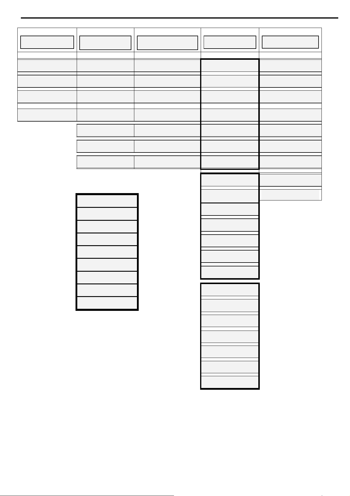
2.2 NEMA Ratings4 . Recommended Motor and Type Unit Ratings.
Light Duty
Nema 10
Current
rating
A HP HP HP A HP HP HP A HP HP HP
8 2 5 5 8 2 5 5 8 2 5 5 QTx0008Uxxxx
17 5 10 15 17 5 10 15 12 3 7.5 10 QTx0017Uxxxx
34 10 25 30 31 10 20 25 31 10 20 25 QTx0031Uxxxx
54 20 40 50 44 15 30 40 44 15 30 40 QTx0044Uxxxx
65 20 50 60 58 20 40 50 55 20 40 50 QTx0058Uxxxx
72 25 50 60 72 25 50 60 66 20 50 60 QTx0072Uxxxx
104 40 75 100 85 30 60 75 80 30 60 75 QTx0085Uxxxx
130 50 100 125 105 40 75 100 99 40 75 100 QTx0105Uxxxx
156 60 125 150 145 50 100 150 130 50 100 125 QTx0145Uxxxx
170 60 125 150 170 60 125 150 134 50 100 125 QTx0170Uxxxx
262 100 200 250 210 75 150 200 203 75 150 200 QTx0210Uxxxx
387 150 300 400 310 100 250 300 310 100 250 300 QTx0310Uxxxx
414 150 350 400 390 150 300 400 361 150 300 300 QTx0390Uxxxx
480 200 400 500 460 150 350 400 432 150 350 400 QTx0460Uxxxx
610 250 500 580 200 400 400 552 200 400 500 QTx0580Uxxxx
820 820 250 500 500 690 250 500 QTx0820Uxxxx
230V 460V 575V Current
5
Normal Duty
Nema 20
rating6
Heavy Duty
Nema 30
230V 460V 575V Current
rating7
Type Unit
230V 460V 575V
Note:
Select the appropriate ASTAT-XT, according to the main power supply and motor voltage rating.
Use QT1xxxxUxxxx units for power supply and motors rated at 230V-500V
Use QT2xxxxUxxxx units for power supply and motors rated at 460V-600V
4
Ratings in Amps. given for ambient temperature up to 40°C and 1000m altitude.
For higher ambient temperature between 40°C and 50°C, derate the current by 2.5% for each °C that is above 40°C.
5
Light duty ratings, only NEMA Class 10 protection is allowed.
6
Normal duty ratings, NEMA Class 10 and 20 protections are allowed.
7
Heavy duty ratings, NEMA Class 10, 20 and 30 protections are allowed
Page 10

2.3 Thermal Characteristics
10 • Types and Ratings
The ASTAT-X
T allows the user to select motor protection according IEC Class 10, 20 and NEMA 10, 20 or 30,
selectable by Overload Class parameter (refer to section
4.7.2 page 27)
Page 11

3. TECHNICAL SPECIFICATIONS
3.1 General Specifications
11 • Technical Specifications
General Info
rmation:
Supply Voltage: Line to line 230-690V (to be specified) + 10%-15%
Frequency: 45 – 65 Hz (fixed or variable frequency source)
Control Supply: Either 110VAC or 230VAC (to be specified) +10% - 15%
Control Inputs: Either 90-230VAC or 24VDC (to be specified)
Load: Three phases, three/six wires, squirrel cage induction motor
Connection type: Standard 3 wire U, V, W connection, or 6 wire Inside Delta (programmable)
Rated Insulation Voltage: 1,000V
Rated Impulse Voltage: 4kV
Form designation: Form 1
This product was tested for compliance with IEC 60947-4-2 for class A equipment.
Start-Stop Parameters:
Starter Current: ASTAT-XT’s rated current according to its nameplate.
Motor Current: Motor Full Load Ampere (Im) 50-125%8 of Starter Current.
Start/Stop Curve 0
2 standard starting and stopping curves
(Standard)
Pump Control Curves (1!,
2!, 3!)
6 field selectable curves preventing over-pressure during start and water hammer
during stop
Torque Control Curve (4) 2 selectable curves preventing over-pressure during start and water hammer during
stop. In addition, these curves may be used for torque control starting of constant
torque applications.
Kick Start Duration: A pulse of 80% Un, for an adj. time 0.1-1 Sec, for starting high friction loads
Starting Voltage: 10-50% Un (5-80%9)
Initial Current:
100-400% In. A single current control starting curve. It appears when Starting
Voltage is displayed, the up arrow is pressed and Starting Voltage has
reached its max.
Current Limit: 100-700% of Motor Current
Ramp UP Time: 1-30 Sec (1-90 sec9)
Ramp DOWN Time: 1-30 Sec (1-90 sec9)
DUAL Settings Parameters: Secondary start stop characteristic for: Starting Voltage, Starting Current, Current
Limit, Ramp UP, Ramp DOWN and Motor Current.
Energy Saving: Energy save for lightly loaded motors
Slow Speed Torque: Torque while motor is at 1/6 nominal speed
Motor Protection:
Too Many Starts: Maximum number of starts, range: Off or 1-10, during a time period 1-60 min.
Starts Inhibit: Time period 1-60 min, when starting is prevented, after too many starts fault
Long Start Time (stall
Maximum allowable starting time 1-30 sec. (1-250 Sec9)
protection):
Over Current (JAM Fault): Three trip functions:
At all time
- If I > 850% of Starter Current it trips the ASTAT-XT within 1 cycle
(overrides the value of the O/C – JAM Delay setting).
At starting process
- If I > 850% of Motor Current it trips the ASTAT-XT after O/C
JAM Delay (see here after)
At run time
- If I > O/C – JAM Fault setting of Im it trips the ASTAT-XT after O/C
JAM Delay
Electronic Overload: Can be set as IEC Class 10, 20 or NEMA Class 10, 20 or 30.
Can be set to operate at all times, disabled or operate during Run only.
Under Current: Trips when current drops below 20-90% of Motor Current, time delay 1-40 sec.
Optional auto reset after time delay.
Under Voltage: Trips when main voltage drops below 120-600V, time delay 1-10 Sec. Optional Auto
Reset.
Over Voltage: Trips when main voltage increase above 250-750V, time delay 1-10 sec.
8
Refer to sections 2.1 page 8 and 2.2 page 9 for detailed information.
9
Refer to section 5.5.5 page 50 for expanded setting.
Page 12

12 • Technical Specifications
Phase Loss, Under/over
Frequency:
Phase Sequence: Trips when phase sequence is wrong
Long Slow Speed Time: Trips if operating at slow speed TRQ for more than 1-30 sec (1-250 sec9)
Wrong Connection: Prevents starting, trips if motor is not connected / incorrectly connected to the
Shorted SCR: Trips if one or more SCRs have been shorted
Heat Sink Over
Temperature:
External Fault: Trips when an external contact closes for 2 sec.
Motor Thermistor: Trip level setting 1-10KΩ, trips when resistance decreases below the level set
Control:
Displays: LCD in 4 – Field selectable languages and 8 LEDs
Keypad: 6 keys for easy setting
Aux Contact – Immediate: 1 C/O, 8A, 250VAC, 2000VA
Aux Contact – End Of
Ramp:
Fault Contact: 1 C/O, 8A, 250VAC, 2000VA
Communication: RS 485 with Modbus protocol for full control and supervision
Communication (optional): Profibus DPV1 for full control and supervision
Communication (optional): DeviceNettm for full control and supervision
Temperatures Operating: -10° to 50°C
Storage: -20° to 70°C
Standards:
Dielectric Test: 2500VAC
Degree of Protection: IP 20 for QTx0008 - QTx0072 ; IP 00 for QTx0085 – QTx1400
Pollution Degree: 3
EMC Emissions: EN 61000-6-4 CISPR 11 Class A
Immunity: EN 61000-6-2 ESD 8KV air, IEC 801-2;
Safety: EN IEC 600947-4-2 and EN IEC 60947-1 Related to safety requirements.
Rated Operational Current AC:53a:4-30: 50-4
Normal Service Conditions:
Altitude: Up to 1000m.
Humidity: 95% at 50°C or 98% at 45˚C
Fan and Control Consumption Ratings:
QTx0008 to QTx0031: No fan Total approximate consumption: 150VA
QTx0044 to QTx0072: Fan 35 VA Total approximate consumption 185VA
QTx0085 to QTx0170 :Fan 60 VA Total approximate consumption 210VA
QTx0210 to QTx0390 : Fans 105 VA (35VA x 3) Total approximate consumption 255VA
QTx0460 to QTx1400A : Fans 150 VA (50VA x 3) Total approximate consumption 300VA
Trips when one or two phases are missing, or frequency is < 40Hz or > 65Hz.
Optional auto reset.
ASTAT-XT (not active in D.Set: Generator Parameters)
(not active in D.Set: Generator Parameters)
Trips when heat-sink temperature rises above 85°C
1 C/O, 8A, 250VAC, 2000VA
Electric RF field 10 V/m, 20-1000Mhz, IEC 801-3
Fast transients 2KV, IEC 801-4
UL508C
Page 13

13 • Technical Specifications
3.2 Weight
Model Weight
Kg Lbs
QTx0008Uxxxx 4.2 9.3
QTx0017Uxxxx 4.2 9.3
QTx0031Uxxxx 5.3 11.7
QTx0044Uxxxx 6.7 14.8
QTx0058Uxxxx 6.7 14.8
QTx0072Uxxxx 6.7 14.8
QTx0085Uxxxx 15.2 33.5
QTx0105Uxxxx 15.2 33.5
QTx0145Uxxxx 15.2 33.5
QTx0170Uxxxx 15.2 33.5
QTx0210Nxxxx 32.7 72.1
QTx0210Uxxxx 46.5 102.5
QTx0310Nxxxx 32.7 72.1
QTx0310Uxxxx 46.5 102.5
QTx0390Nxxxx 32.7 72.1
QTx0390Uxxxx 46.5 102.5
QTx0460Nxxxx 58.4 128.7
QTx0460Uxxxx 61.8 136.2
QTx0580Nxxxx 63.2 139.3
QTx0580Uxxxx 69.5 153.2
QTx0650Nxxxx 64.8 142.9
QTx0820Uxxxx 69.5 153.2
QTx0950Nxxxx 86.7 191.1
QTx1100Nxxxx 169.8 374.3
QTx1400Nxxxx 175.5 386.9
3.3 I/O Terminal Board Specifications
Refer to dra
wing on page 17.
Terminal Function Description
1L1, 3L2, 5L3 Connection to mains voltage up
to 690V
A, B, C Preparation for bypass
connection
2T1, 4T2, 6T3 Connection to motor
G Connection to ground For proper operation and for safety reasons soft ASTAT-XT
Terminal L Control phase The control voltage operates the electronic circuitry and the
Terminal N Control neutral (return) Two control voltages are available:
Thyristor’s PIV rating, internal circuitry and insulation defines
three voltage levels:
QT 1 x : for 230-500V +10%/ -15% 50/60Hz
QT 2 x: for 460-600V +10% /-15% 50/60Hz
QT 3 x: for 690V +10% /-15% 50/60Hz
Each ASTAT-XT is suitable for one of the above levels & for
50/60 Hz.
Bypass preparation is standard in all models.
All models from ASTAT-XT 950A and up must
be operated
with a bypass contactor.
Refer to section
5.3 page 47 for more details.
Connect motor’s terminals to these terminals/busbars.
must be properly grounded.
fans (when they exist).
QT x xxxx x 1 x x S for 110V +10%/-15% 50/60Hz
QT x xxxx x 2 x x S for 230V +10%/-15% 50/60Hz
Page 14

14 • Technical Specifications
Terminal Function Description
Terminal F Fan control An internal jumper, connected between the fan and
terminal 2 enables three modes of operation (refer to section
5.6 page 51).
For fan power consumption, see technical specification in
section
Terminal 4 Input – STOP command.
• Input from a N.C. contact
• To stop the motor, disconnect
Control Input voltage from
• Control Input voltage (STOP, SOFT STOP, START, terminal
• The Control Inputs are opto-coupled and isolated from the
terminal 4 for at least
250mSec. (no SOFT STOP)
Terminal 5 Input – SOFT STOP command10.
• Input from a N.C. contact
• To SOFT STOP the motor
Control Input voltages available:
QT x xxxx x x 1 x S for 90-230V +10%/-15% 50/60Hz.
QT x xxxx x x 2 x S for 24VDC +10%/-15%.
disconnect Control Input
voltage from terminal 5 for at
least 250mS
Terminal 6 Input – START command11.
• Input from a N.O. contact.
• To SOFT START the motor,
connect Control Input voltage
to terminal 4 for at least
250mSec.
Terminal 7 Programmable input – Energy
Refer to section 4.7.8.1 page 41.
Save / Slow Speed / Reset
Terminal 8 Programmable input – Dual Set
/ Reverse / Reset
Terminal 9 12 Common to terminals 4-8.
This terminal is a reference for terminals 4, 5, 6, 7 &
8.
Terminal 10 Immediate Relay (N.O.) Immediate Relay (RUN relay) is the immediate output relay.
• Voltage free 8A, 250VAC, 2000VA max.
Terminal 11 Immediate Relay (N.C.) • The relay is energized upon the START signal.
Terminal 12 Immediate Relay (Common) • The relay is de-energized when one of the following occurs:
• When SOFT STOP is operated - the relay is de-energized at
• The Immediate Relay (RUN relay) can be used for the
• The relay incorporates ON and OFF delays of 0-3600 sec.
Terminal 13 Programmable Fault Output
relay (N.O.)
Terminal 14 Programmable Fault Output
relay (N.C.)
Voltage free 8A, 250VAC, 2000VA max. changes its position
upon fault.
The contact is programmable to function as At Fault
Close or At Fault Open.
10
If SOFT STOP is not required, connect a jumper between terminals 4 and 5.
11
Motor will start only if STOP (terminal 4) and SOFT STOP (terminal 5) terminals are connected to Control Input voltage.
To reset a fault the START command must be removed.
12
When Control Supply and Control Input voltage are from the same source, connect a jumper between terminals 3 and 9.
3 page 11.
inputs 7 and 8) can be the same as Control Supply
(terminals 1, 3) or voltage from a different source.
microprocessor circuitry.
Fault, Control Supply outage or STOP signal.
the end of the SOFT STOP process.
following purposes: Release a brake of a motor, Interlock
with other systems, Signalling, Delay the opening of a line
contactor at the end of SOFT STOP, thus allowing current to
decrease to zero before opening the contactor or to switch
to / from DUAL settings with a time delay from the START
signal (see Special Starting section
each. Refer to section
4.7.8 page 40 for Relay ON Delay
6.2.3.1 page 57).
programming.
Page 15

15 • Technical Specifications
Terminal Function Description
Terminal 15 Programmable Fault Output
relay (Common)
Terminal 16 Programmable EOR (End Of
Ramp) Output relay (N.O.)
Terminal 17 Programmable EOR (End Of
Ramp) Output relay (N.C.)
Terminal 18 Programmable EOR (End Of
Ramp) Output relay (Common)
Terminal 19 External Fault input Input from a N.O. contact that is connected between
Terminal 21 Neutral connection When a mains neutral wire is available, connect terminal 21
When the At Fault Close function is selected, the relay
is energized upon fault. The contact returns to its original
position when one of the following occurs:
• The fault has been removed and ASTAT-XT was reset.
• Disconnection of Control Supply
When the At Fault Open function is selected, the relay is
energized immediately when the Control Supply is connected
and de-energizes when one of the following occurs:
• Fault
• Control Supply disconnection
Refer to section
4.7.8 page 40 for PROG. Fault Relay
programming.
Voltage free 8A, 250VAC, 2000VA max. changes its position at
the end of ramp, after an adjustable time delay (Contact
Delay), 0 – 120 sec.
The contact returns to its original position when Energy
Save is operated, on Soft Stop or Stop signals, on Fault
condition, or upon voltage outage.
The EOR (End Of Ramp) contact can be used for:
• Closing a bypass contactor
• Activating a valve after compressor has reached full speed
• Loading a conveyor after motor reached full speed.
Refer to section
4.7.3 page 29 for EOR Relay Delay
programming
terminals 19 and 21. The ASTAT-XT will trip 2 seconds after
the contact closes.
Notes:
• Wires connecting the External Fault contact to terminal 19
should not exceed 1 meter in length.
• External Fault can be used only when terminal 21 is
connected to neutral or ground.
• Only potential free contacts may be connected to terminal
19.
• Do not connect any voltage to terminal 19.
• Any connection of voltage to this terminal may disrupt
ASTAT-XT operation, and cause ASTAT-XT or motor damage.
• Refer to section 8.12 page 67 for the External Fault wiring
diagram.
to neutral. Terminal 21 serves only as a voltage reference to
the control circuitry.
Caution
• ASTAT-XT circuitry incorporates an internal artificial neutral,
:
which should only be used, when the mains system is not
grounded and mains neutral connection is not available.
• Only potential free contacts may be connected to terminal
21.
• Do not connect any voltage to terminal 21.
Any connection of voltage to this terminal may disrupt
ASTAT-XT operation, and cause ASTAT-XT or motor damage.
• Refer to section 8.1 on page 62 for terminal 21 connection.
Page 16
16 • Technical Specifications
Terminal Function Description
Terminal SG No connection • Standard RS485, half duplex with Modbus protocol, baud
rate 1200, 2400, 4800, 9600 BPS.
Terminal D- RS-485 communication (-) • Twisted shielded pair should be used.
Connect shield to ground on the PLC/Computer side.
Terminal D+ RS-485 communication (+) • Terminals 4 & 5 must be wired to Control Supply for
operation in communication mode (refer to section
page 70 for wiring diagram).
• Up 32 units can be connected for Modbus RS485
communication. For reliable communication, units should
be installed in the vicinity of 200m maximum, from the first
to the last unit.
• Refer to section 4.7.9 page 42 for programming.
• Refer to Appendix A of this manual for Modbus protocol
manual.
Terminal 28 Thermistor input (T1) Thermistor input is programmable as a PTC or NTC type
thermistor. The trip value is adjustable between 1-10Kohm,
preset delay of 2 Sec.
Terminal 29 Thermistor input (T2)
Connect thermistor and/or Analog output shield to ground
terminal.
Terminal 30 Ground Analog output (0-10VDC or 0-20mA or 4-20mA)
8.16
Terminal 31 Analog output (-) Reflects motor current and is related to 2xIm. i.e., Full scale
(10VDC or 20mA) is related to 2xIm.
Terminal 32 Analog output (+) Note:
Refer to section
5.7 page 51 for analog output PCB dip switch
setting.
• Refer to section 4.7.8 page 40 for Analog Output
programming.
• Refer to section 4.7.7 page 38 for Thermistor Type and
Thermistor Trip programming.
D-9 connector Profibus communication
(optional)
• Profibus DPV0 and DPV1, up to 12 MBPS.
• D type 9 pin connector is applied.
• Control, monitoring and setting parameters can be achieved
via the Profibus connection.
• Setting is possible only when DPV1 is implemented.
• Refer to section 4.7.10 page 42 for programming.
• Refer to Appendix B of this manual for Profibus protocol
manual.
Terminal V- 0 Volt external power supply
Terminal CL Negative data line
DeviceNet communication
(optional)
Terminal Dr Cable shield
Terminal CH Positive data line
Terminal V+
+24V external power supply
Page 17
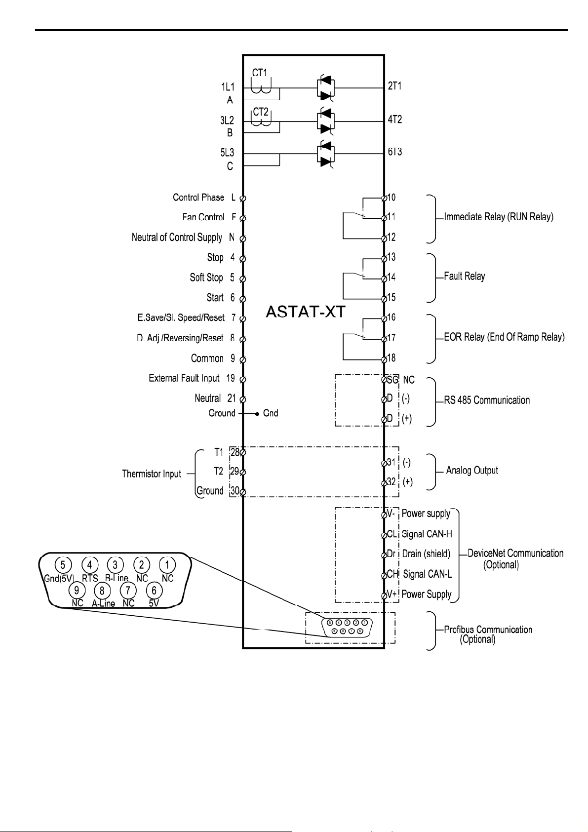
3.4 I/O Wiring
17 • Technical Specifications
Page 18
18 • Technical Specifications
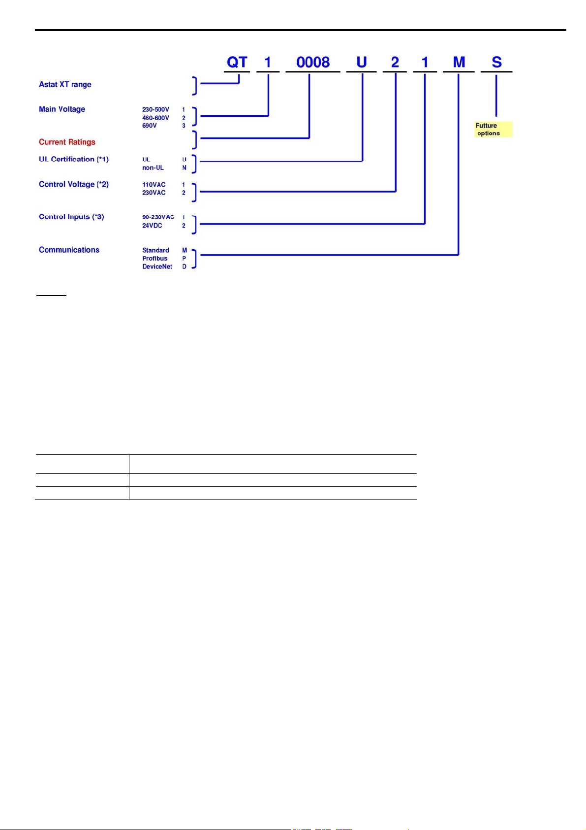
3.5 Ordering Information
Notes:
cUL Certification
(*1) – ASTAT-XT up to 600V, and up to 170A (Cat Numbers up to to QT10170_ or QT20170) are always cUL
Control and Inputs Voltage
(*2) ASTAT XT standard Control Voltage configuration is option 2, Voltage 230VAC, +10%, -15%
(*3) ASTAT XT standard configuration for Inputs is option 1, Voltage 90-230VAC, +10%, -15%
3.5.1 Ordering Accessories
certified. Option “N” not available
- Units QT1 or QT2 from QTx0950_ up to QTxx1400 are not UL certified. Option “U” not available.
- Units QT3x, rated to 690V, are not UL certified. Option “U” not available
Catalog Number
QTAKPADKIT1 Keypad mounting kit for ASTAT-XT up to 72A
QTAKPADKIT2 Keypad mounting kit for ASTAT-XT above 72A
Description
Page 19
19 • Technical Specifications
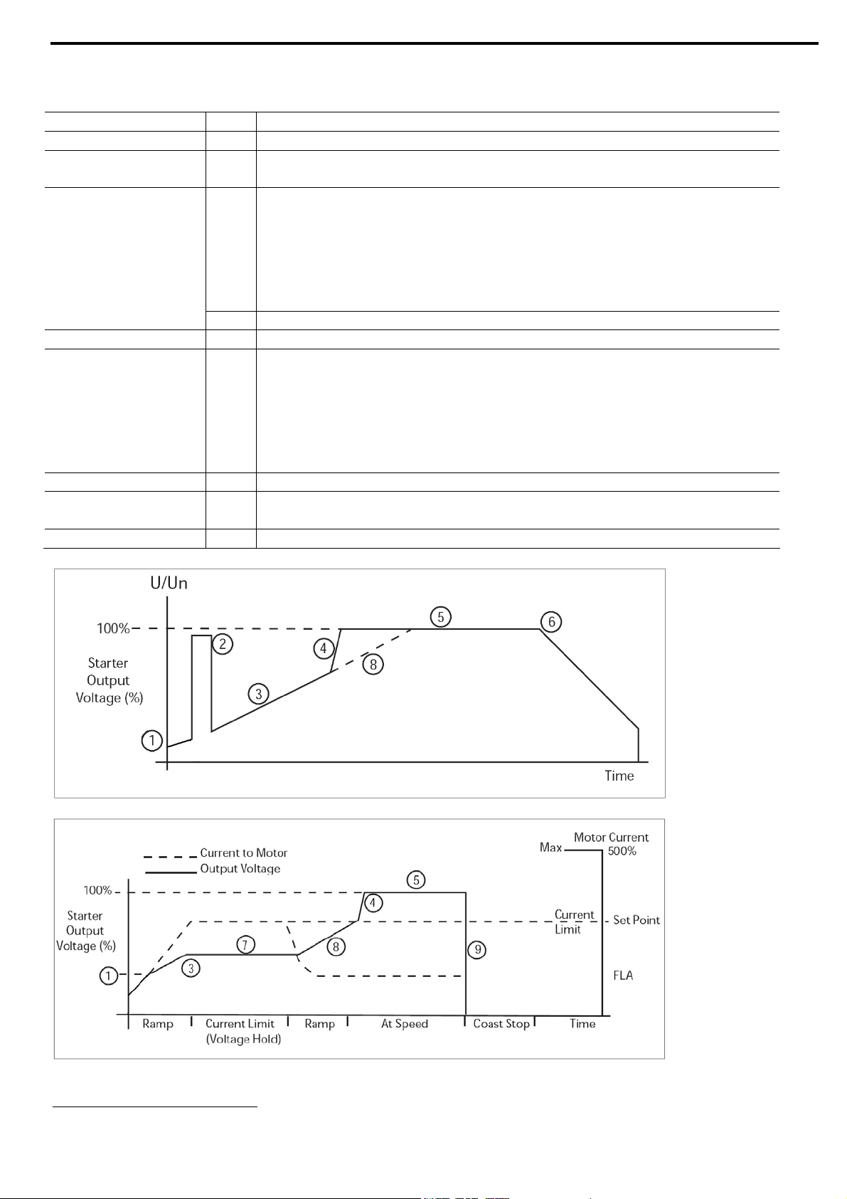
3.6 Operating Modes
Operating Mode
Key Description
Starting Voltage 1 5 to 80% Un. Adjustable via Starting Voltage parameter.
Kick Start 2
Fixed level of 80% Un with an adjustable time, 0-1 sec., via Kickstart
Time parameter.
13
1-30 sec. (1-90
Secondary ramp 1-30sec. (1-90
sec.). Adjustable via Ramp UP Time.
13
sec.). Adjustable via Ramp UP-2
parameter.
Acceleration Ramp 3
Ramp up modes available are:
Soft Start Curve 0 (Standard)
Soft Start Curve 1!!-3!!
Soft Start Curve 4(Torque) for linear torque control
4 Fast ramp (if the motor is up to speed before the end of normal ramp time)
Running mode 5 Nominal voltage
13
Deceleration ramp 1-30sec. (1-90
Secondary ramp 1-30sec. (1-90
sec.). Adjustable via Ramp DOWN Time.
13
sec.). Adjustable via Ramp DOWN-2
parameter.
Soft stop mode 6
Ramp down modes available are:
Soft Stop Curve 0 (Standard)
Soft Stop Curve 1!!-3!!
Soft Stop Curve 4(Torque) for linear torque control
7 Current limiting set point (100-500%xMotor Current)
8
Acceleration ramp (continuation after motor amps drop below the current
limit).
9 Standard stopping (coast to rest)
Starting by voltage ramp:
Starting by current limitation:
13
Refer to section 5.5.5 page 50 for expanded setting.
Page 20
20 • Control Keypad
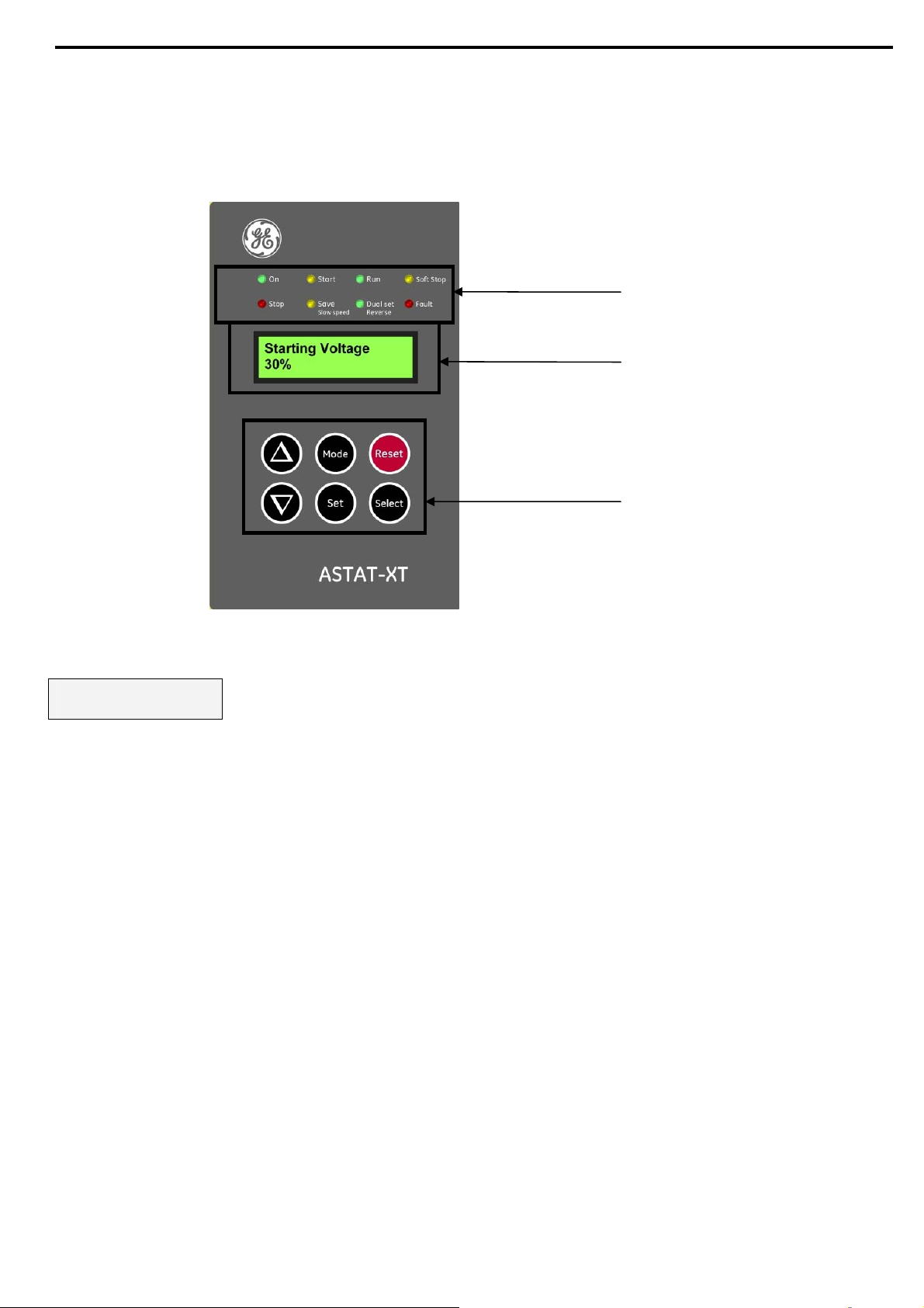
4. CONTROL KEYPAD
The control keypad is the interface between the ASTAT-XT and the user.
The ASTAT-XT control keypad features:
Eight indication LEDs (On, Start, Run, Soft Stop, Stop, Save/Slow Speed, Dual Set/Reverse, Fault)
Two lines of 16 alphanumeric characters each with selectable languages – English, Italian, German, and Spanish.
Six push-buttons - Mode, Reset, Select, Set, Up (▲) and Down (▼) keys.
(1)
(2)
(3)
ASTAT-XT control keypad
4.1 LCD Arrangement
Starting Voltage
30%
Upper line displays the function.
Lower line displays the setting and\or measured values.
Page 21
4.2 Push-Buttons
Mode
Select
Scrolls throu
When a mode name is displayed, pressing this button drills down to the parameters for that mode.
When a parameter is displayed, pressing this button scrolls to the next parameter.
Allows the operator to increment adjusted values shown in the display. Operator should press this
▲
button once to increment one value, or continuously to rapidly increment values up to the maximum
value.
Allows the operator to decrement adjusted values shown in the display. Operator should press this
▼
button once to decrement one value, or continuously to rapidly decrement values up to the minimum
value.
Stores modified parameters only
Set
Settings Xxxxxx Parameters is displayed. After you store a parameter successfully Data
Saved OK will display.
21 • Control Keypad
gh the display and programming menus of the ASTAT-XT.
when you have scrolled through all parameters and Store
15
14
Reset
Resets the ASTAT-XT after a fault has been dealt with and the start command has been removed. This
cancels the fault displayed and allows you to restart the motor.
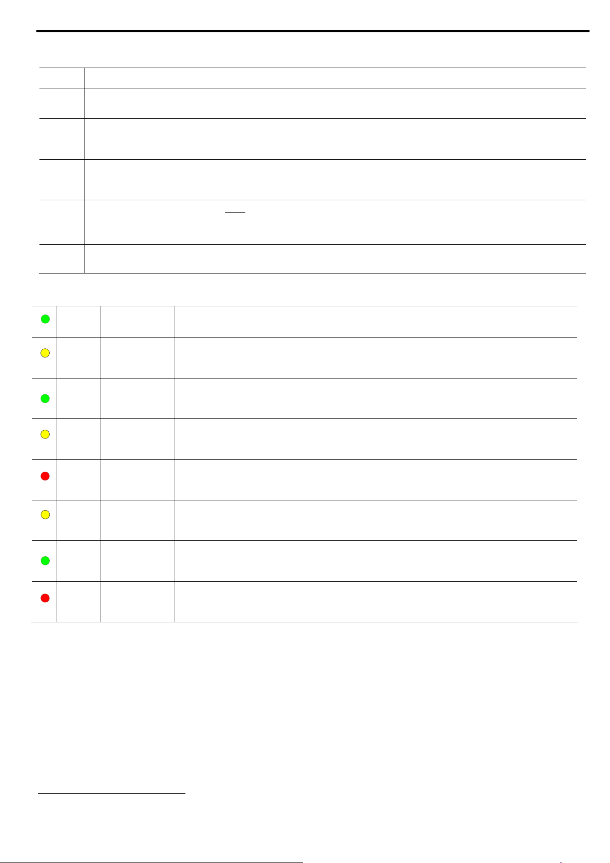
4.3 Status LEDs
Green
On Lights when the control supply voltage is connected to the ASTAT-XT.
Yellow Start Lights during soft start, indicating that motor supply voltage is ramping up.
Green Run
Lights after completion of the starting process, indicating that motor is receiving
full voltage. This LED flashes during slow speed operation.
Yellow Soft Stop Lights during soft stop, indicating that the motor supply voltage is ramping down.
Red Stop Lights when the motor is stopped.
Yellow
Green
Save/Slow
Speed
Dual
set/Reverse
Lights when Energy Saving is in operation.
Flashes when the motor is running in Slow Speed.
Lights when Dual Settings is in operation.
Flashes when the motor is running in Slow SP Reverse.
Red Fault Lights upon operation of any of the built-in protections.
4.4 Reviewing and Modifying Parameters
Press the Mode key several times until you reach the required mode page.
Press the Select key to review parameters for this mode.
Once you reach the required parameter, use the ▼ or ▲ keys to modify its value.
To store the new parameters, press the Select key until the Store Settings Xxxxxx Parameters message
displays and then press the Set key. The Data Saved OK message will display for 2 seconds.
Note:
After completing parameter settings:
• Turn control voltage OFF
• Wait 3 seconds
• Reconnect control voltage
14
Pressing Mode continuously increases the speed at which the parameters change.
15
Pressing the Set button at any other time has no effect.
Page 22
22 • Control Keypad
• Verify that all parameters are set correctly.
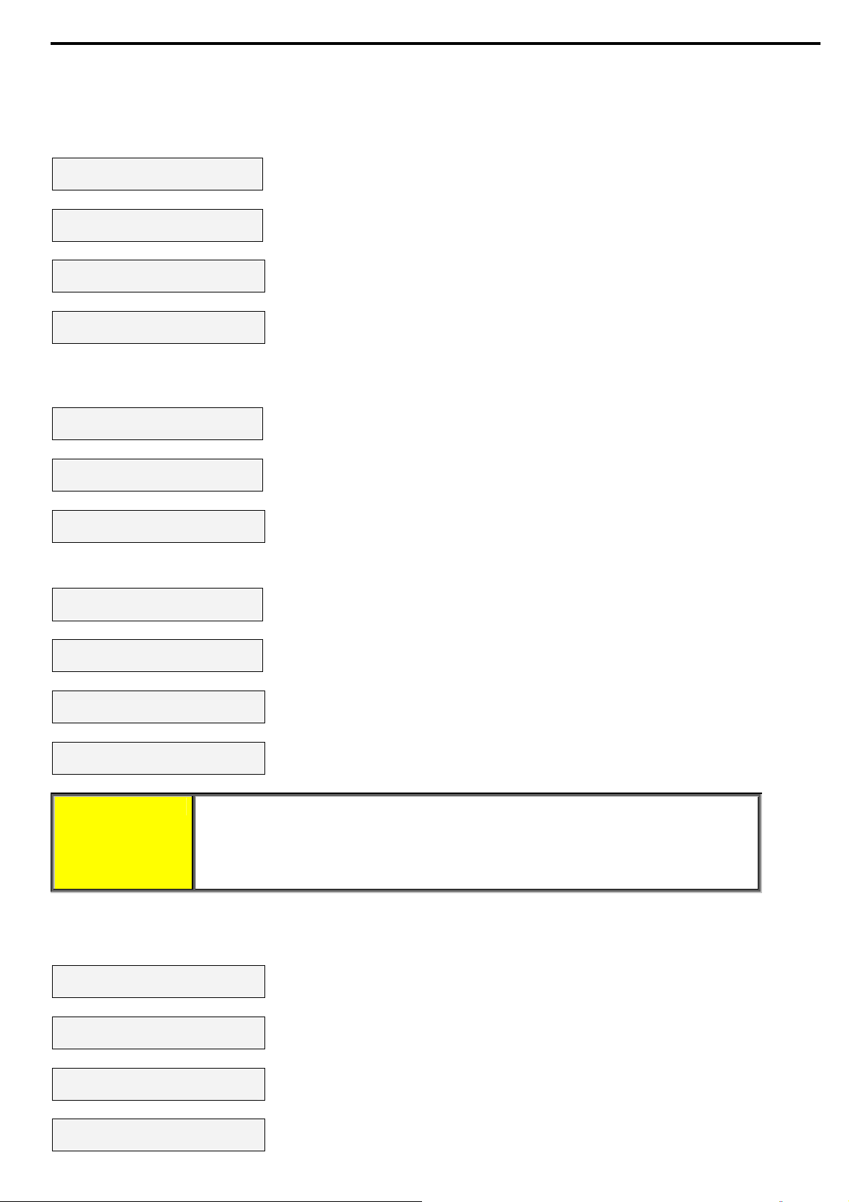
4.5 Special Actions Performed in Test/Maintenance Mode
4.5.1 Run Self Test
Press
the Mode and ▼ keys simultaneously. The LCD will display:
Test/Maintenance
Statistics
Press the Select key. The LCD will display:
Auto Test.
Press UP Key
Press the ▲ key. The LCD will display:
Self Test Passed
And after a few seconds the LCD will display:
Motor Current
0
4.5.2 View Software Version
Press
the Mode and ▼ keys simultaneously. The LCD will display:
Test/Maintenance
Statistics
Press the Select key twice. The LCD will display:
Firmware Version
STRT.GE-031208
Press the Mode and ▼ keys simultaneously to exit the Test/Maintenance mode. The LCD will display:
Motor Current
0
4.5.3 Obtain Default Parameters
Press the Mode and ▼ keys simultaneously. The LCD will display:
Test/Maintenance
Statistics
Press the Select key three times. The LCD will display:
Store Settings
Default data
Press the Set + Mode keys simultaneously. The LCD will display:
Data Saved OK
And after a few seconds the LCD will display:
Motor Current
0
CAUTION! Obtaining Default Data erases all previously modified settings and requires the
operator to reprogram all parameters that differ from the factory default.
Note: It is especially important to reprogram the Starter Current (as shown
on the name plate of the ASTAT-XT), Motor Current and voltage protection
values again.
4.5.4 Reset Statistical Data
Press
the Mode and ▼ keys simultaneously. The LCD will display:
Test/Maintenance
Statistics
Press the Select key four times. The LCD will display:
Reset Statistics
Press the Reset + Set keys simultaneously. The LCD will display:
Data Saved OK
And after a few seconds the LCD will display:
Statistical Data
- **** -
Page 23
23 • Control Keypad
Press the Mode and go back to:
Motor Current
0
4.5.5 Calibrate Voltage and Current (Factory Use Only!)
the Mode and ▼ keys simultaneously. The LCD will display:
Press
Test/Maintenance
Statistics
Press the Select key five times. The LCD will display:
Calibration VOLT
0 VOLT
Press the Select key. The LCD will display:
Calibration CURR
5% of Ir
Press the Mode and ▼ keys simultaneously to exit the Test/Maintenance mode.
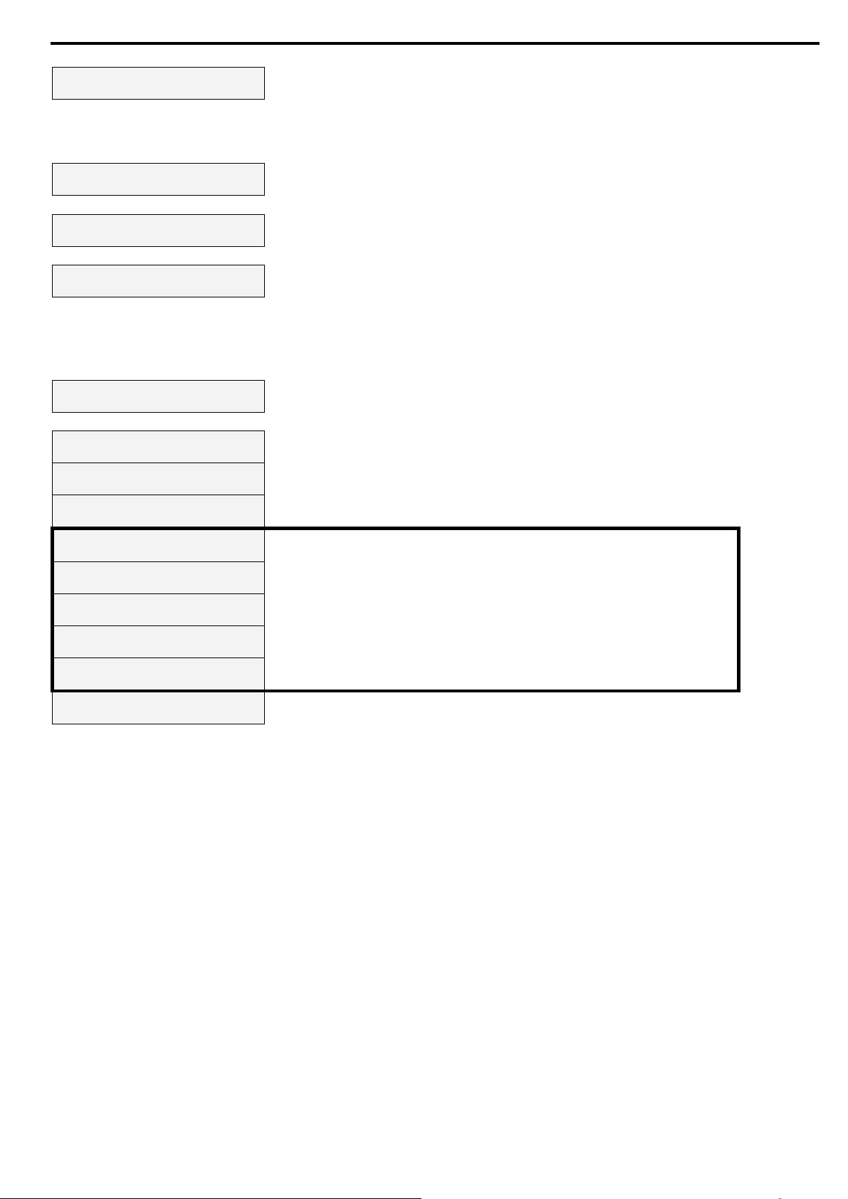
4.6 Mode Pages
Upon init
iation of the ASTAT-XT, the LCD displays motor’s operating current:
Motor Current
0
You can review all mode pages by pressing the Mode key:
Main Settings
- **** Start Settings
- **** Stop Settings
- **** DUAL Settings
Parameters
Slow SP & Saving
Parameters
Fault Settings
- **** -
These pages are skipped if ASTAT-XT is programmed to Minimized
Mode and are shown only in Maximized Mode. Refer to section
on page 49 for changing mode from Minimized
Mode.
I/O Settings
Parameters
COMM. Parameters
- **** Statistical Data
- **** -
5.5.1
Mode to Maximized
Page 24
24 • Control Keypad
4.7 Overview of All Mode Pages and Factory Defaults
Appears only in
Maximized
Display Page
Main Settings
- **** -
Start Settings
- **** -
Stop Settings
- **** -
DUAL Settings
16
Parameters
Function & Default Function & Default Function & Default Function & Default Function & Default
Motor Current
0
Starter Current
58 AMP.
Soft Start Curve
0(Standard)
Soft Stop Curve
0(Standard)
Starting VOLT-2
30%
Line Voltage
0 Volt
Motor Current
58 AMP.
Kickstart Time
0 SEC.
Ramp DOWN TIME
10 SEC.
Starting CURR-2
100%
Thermistor Input.
3.1 Kohm
LINE/DELTA Conf.
Line
Starting Voltage
30 %
End Torque
0 (MIN.)
Current Limit-2
300% of Im
Undercurrent FLT
0% of Im
Starting Current
100 %
Store Settings
Stop Settings
Ramp UP-2
10 SEC.
Undercurrent DLY
10 SEC.
Current Limit
400% OF Im
Ramp DOWN-2
10 SEC.
O/C JAM Fault
850% OF Im
Ramp UP Time
10 SEC.
Motor Current-2
31 AMP.
O/C JAM Delay
0.5 Sec.
Max. Start Time
30 SEC.
Store Settings
Dual Settings
Overload Class
IEC CLASS 10
Number of Starts
10
Overload Protect
Enabled
Duty Cycle Time
30 Min.
Undervoltage FLT
300 Volt
Start Lockout
15 Min.
Undervoltage DLY
5 SEC.
EOR Relay Delay.
5 Sec.
Overvoltage FLT
480 Volt
Store Settings
Start Settings
Overvoltage DLY
2 SEC.
Store Settings
Main Settings
16
Refer to section 5.5.1 on page 49 for changing mode from Minimized Mode to Maximized Mode.
Page 25
25 • Control Keypad
Only in Max. Mode
Slow SP & Saving
Parameters
16
Only in Max. Mode
Fault Settings
- **** -
16
Only in Max. Mode
16
I/O Settings
Parameters
Only in Max. Mode
COMM. Parameters
- **** -
16
Statistical Data
- **** -
Function & Default Function & Default Function & Default Function & Default Function & Default
Energy Saving
0 (MIN)
Slow Speed TRQ.
8
Max Slow SP Time
30 SEC.
Store Settings
Slow SP & Saving
Phase Loss
Enabled
Phase Sequence
Disabled
Auto Reset
Disabled
Thermistor Type
PTC
Thermistor Trip
Disabled
Undercurrent RST
Disabled
Store Settings
Fault Settings
Appears when in
Test/Maintenance
Test/Maintenance
***Statistics***
Display and default
values
Auto Test
Press UP Key
Firmware Version
STRT-GE-270508
Store Settings
Default Data
Reset Statistics
Calibration VOLT
0 VOLT
Calibration CURR
5% of Ir
PROG. Input #7
Reset
PROG. Input #8
Dual Settings
PROG. Fault Relay
At Fault Close
Relay ON Delay
0 SEC.
Relay OFF Delay
0 SEC.
Analog Output
I, 0...200% OF Im
Store Settings
I/O Settings
COMM. Protocol
Modbus
Baud Rate
9600 (MODBUS)
Parity Check
EVEN
Station Number.
OFF
S. Link Par. Set
DISABLED
Ser. Link Control
DISABLE
Store Settings
COMM. Parameters
COMM. Protocol
Profibus
Baud Rate
AUTO (Profibus)
Parity Check
AUTO (Profibus)
PROFI. Network ID
OFF
S. Link Par. Set
Disabled
Ser. Link Control
Disabled
Store Settings
COMM. Parameters
COMM. Protocol
DeviceNet
Baud Rate
Set Manually
Parity Check
AUTO (DeviceNet)
DeviceNet ID
Set Manually
S. Link Par. Set
Disabled
Ser. Link Control
Disabled
Store Settings
COMM. Parameters
Last Start Time
No Data
Last Start Curr.
No Data
Elapsed Run Time
0 Hours
Number Of Starts
0
Last Fault
No Data
Motor FLT Current
0 % of Im
Fault Counter
0
Previous Fault -1
No Data
PREVIOUS Fault -9
No Data
Note: There are three different groups of COMM. Protocol parameters. Each group of COMM. Protocol parameters
are only valid when its corresponding optional PCB is installed.
Page 26
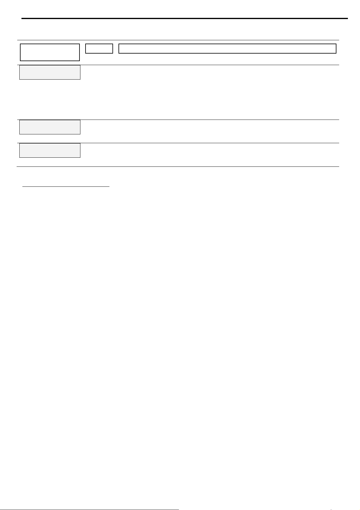
26 • Control Keypad
4.7.1 Display Mode
Function &
17
– Page 018
Unit Description
Default
Motor Current
0
A Displays operating current of the motor.
ASTAT-XT’s Default Display. After pressing the Mode or Select keys, a time
delay is initiated. Following the delay the LCD returns to display Motor
Current.
If current is lower than 0.1 of the rated current of the ASTAT-XT, the display
will show: I < 0.1 Ir
Line Voltage
0 Volt
Thermistor Input
3.1 Kohm
V Displays the mains voltage.
Kohm Displays the resistance level of the motor’s thermistor.
17
Displays in MINIMIZED MODE and MAXIMIZED MODE.
18
Parameters cannot be programmed in page 0.
Page 27
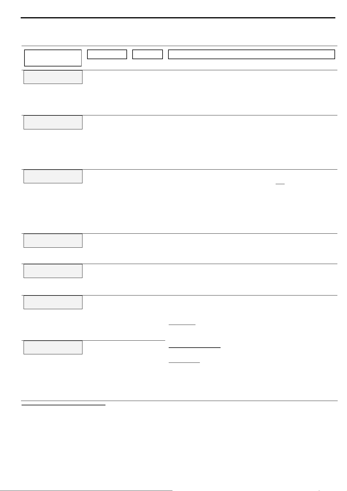
27 • Control Keypad
4.7.2 Main Settings
Function &
Default
Starter Current
58 Amp.
Motor Current
58 Amp.
LINE/DELTA Conf.
Line
19
– Page 1
Range Unit Description
8 – 1400 A Sets ASTAT-XT’s Rated Current (Type Unit)
Check the name plate on the soft starter and make sure that
digits 4 to 7 of the model name are the same as the
Starter Current setting. For example the setting for
model QTx0008Uxxx must be 8 Amp. Refer to section
page 47.
4-175020
Based on % of
Starter
Current
A Sets the motor’s Full load Ampere
Should be programmed as shown on the motor’s name
21
plate.
Note:
When setting Motor Current to a higher level than
Starter Current, Overload Class parameter (see
below) is automatically set to NEMA Class 10.
Line, Inside
Delta
Sets ASTAT-XT’s connection type.22
Factory preset - features and functions not
DELTA Conf. is configured:
Kickstart.
Soft Start Curve selection (Curve 0!! only)
Slow Speed
Phase Sequence Disabled mode
Refer to section
8.20 on page 74 for further information.
5.1 on
active when
Undercurrent FLT
0% of Im
0%=OFF;
20-90
% of
Motor
Current
Sets Undercurrent protection.
Trips the ASTAT-XT when the motor current drops below the
level that was set for a time period longer than
Undercurrent Dly.
Undercurrent DLY
10 SEC.
1-40 sec. Sets the time delay for Undercurrent FLT protection.
Note:
Operational when the motor is running (the RUN LED is lit).
O/C JAM Fault
850% of Im
100-850 % of
Motor
Current
Sets O/C JAM Fault protection.
Operational when ASTAT-XT is energized and has three trip
functions:
At all time
- If I > 850% of Starter Current it trips the
ASTAT-XT within 1 cycle (overrides the value of the O/C JAM
Fault setting).
O/C JAM Delay
0.5 Sec.
0.0 – 5 sec. At starting process - If I > 850% of Motor Current it trips
the ASTAT-XT after O/C JAM Delay
At run time
- If I > O/C JAM Fault setting of Motor
Current it trips the ASTAT-XT after O/C JAM Delay.
Caution:
The O/C JAM Fault is not intended to replace the fast
acting fuses, required to protect the thyristors. Refer to
section
8.18 on page 72.
19
Displays in MINIMIZED MODE and MAXIMIZED MODE.
20
The lower limit can be set as low as 50% of Starter Current. The upper limit is automatically set by the ASTAT-XT and is
between 100 and 126% of Starter Current.
The Motor Current can be set as high as indicated in columns “Current Rating” for Light Duty applications in the tables in
section
21
When the ASTAT-XT is installed in the Inside Delta configuration set:
Motor Current = <rated motor current>/1.73.
22
When the ASTAT-XT is installed in DELTA Conf. set Motor Current = <rated motor current>/1.73.
2.1 page 8 and in section 2.2 page 9.
Page 28
28 • Control Keypad
Function &
Default
Overload Class
IEC CLASS 10
Overload Protect
Enabled
Undervoltage FLT
300 Volt
Undervoltage DLY
5 SEC.
Range Unit Description
IEC CLASS 10;
IEC CLASS 20;
NEMA CLASS
10;
NEMA CLASS
20;
NEMA CLASS
30;
Sets Overload CLASS.
Overload Class is operational as programmed in the
Overload Protect parameter. (see next parameter)
The O/L circuitry incorporates a thermal memory register
that calculates heating minus dissipation of the motor. The
ASTAT-XT trips when the register fills up.
The time constant for cool down after overload trip is:
For IEC/NEMA Class 10 – 320seconds
For IEC/NEMA Class 20 – 640seconds
For NEMA Class 30 – 960seconds
Refer to section
2.3 on page 10 for thermal characteristic.
Note:
When setting Motor Cu
rrent to a higher level than
Starter Current, Overload Class parameter is
automatically set to NEMA Class 10.
Enable after
EOR;
Enabled;
Disabled;
Sets Overload Protection operation.
Enable after (End Of Ramp) will set the overload
protection to be operative after starting process is completed
and (End Of Ramp) relay is energized.
Enabled will set the overload protection to be operative at
all time.
Disabled will set the overload protection not to be
operative at all time.
ATTENTION!
When Overload Protect is set to Disabled the motor
is not protected for Overload!!
120-600
V Sets Undervoltage Fault level.
Trips the ASTAT-XT when mains voltage drops below the level
that was set for a time longer than Undervoltage DLY.
1 –10 sec. Sets Undervoltage Fault delay23
Overvoltage FLT
480 Volt
250-750
V Sets Overvoltage Fault level.
Trips the ASTAT-XT when mains voltage increases above the
level that was set for a time longer than Overvoltage
DLY. Can not be set lower than the Undervoltage FLT
setting.
Overvoltage DLY
2 SEC.
Store Settings
Main Settings
1 –10 sec. Sets Overvoltage Fault delay.24
Storing modified parameters25
To store selected parameters scroll through all parameters
until you reach Store Settings Main Settings, then
press the Set key.
After you store a parameter successfully the Data Saved
OK message will display.
If ASTAT-XT fails to store the parameter the LCD Will display
the Storage Error message (refer to section
7 on page
59 for more details).
23
Becomes operational only after the start signal.
When voltage drops to zero (voltage outage) the ASTAT-XT will trip immediately, thus overriding the delay.
24
Becomes operational only after the start signal.
25
Pressing the Set key when the Store Settings Xxxxx Settings message does not appear on the display has no
effect.
Page 29
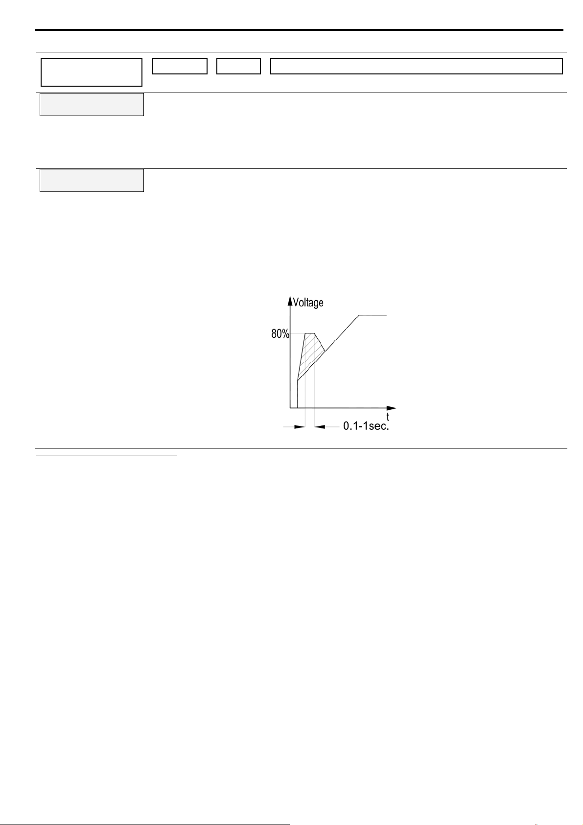
4.7.3 Start Settings
26
– Page 2
29 • Control Keypad
Function &
Default
Soft Start Curve
0(Standard)
Kickstart Time
0 Sec.
Range Unit Description
0
(Standard)
Sets ASTAT-XT’s Soft Start Curve.
Refer to section
4.7.3.1 on page 32.
27
1 !!
2 !!
3 !!
4 (Torque)
0 –1.0 sec. Sets ASTAT-XT’s Kickstart Time.28
Kickstart level is 80% Un.
Intended to start high friction loads that require high starting
torque for a short time.
A pulse of 80% Un without Current Limit is initiated to break the
load free.
Kickstart Time is adjustable, 0.1–1sec. After this pulse the
voltage is ramped down to Starting Voltage setting
before ramping up again to full voltage according to the Start
Settings.
26
Displays in MINIMIZED MODE and MAXIMIZED MODE.
27
When ASTAT-XT is connected in DELTA Conf. only Soft Start Curve 0 (Standard) is applied.
28
There is no Kickstart function when ASTAT-XT is connected in DELTA Conf.
Page 30
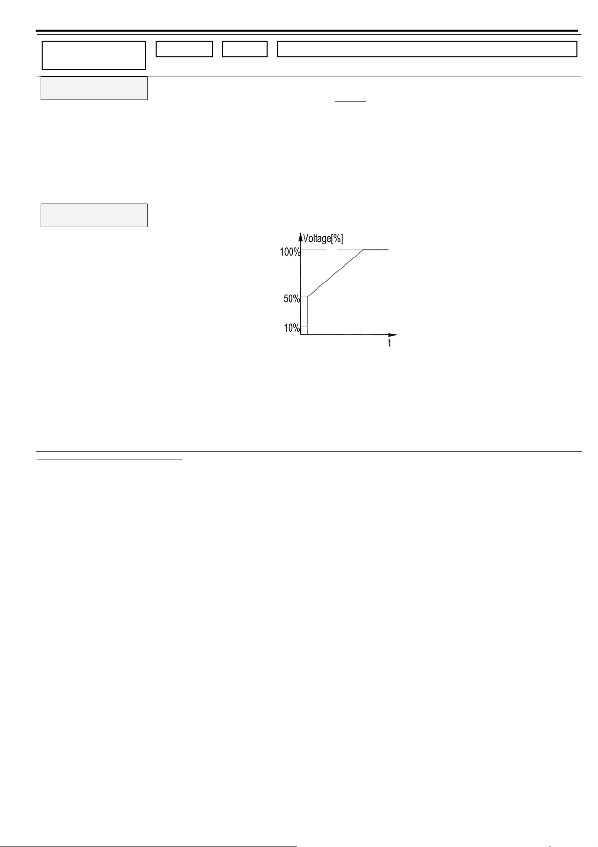
30 • Control Keypad
Function &
Default
Starting Voltage
30 %
Starting Current
100 %
Range Unit Description
10-50%
After
reaching
50% the
display
changes to:
Starting
Current
100-400%
29
% of
mains
voltage
Sets the motor’s Starting Voltage.
The motor’s torque
is directly proportional to the square of the
voltage.
This adjustment also determines the inrush current and
mechanical shock. A setting that is too high may cause high
initial mechanical shock and high inrush current. This can occur
even if Current Limit is set low because the Starting
Voltage setting overrides the Current Limit setting.
A setting that is too low may result in prolonged time until the
motor starts to turn. In general, this setting should ensure that
the motor starts turning immediately after start signal.
Note:
When Starting Voltage is set its maximum value, this
displays changes to Starting Current.
When Starting Current is set the ASTAT-XT causes current
ramp instead of voltage ramp.
29
The range of the Starting Voltage can be extended to 5-80% by using the EXPANDED SETTING as described in section 5.5.5
page 50.
Page 31

31 • Control Keypad
Function &
Default
Current Limit
400% of Im
Range Unit Description
100-700% % of
Motor
Current
Sets the motor’s highest current during starting.
A setting that is too high will increase the current drawn from
mains and speed up acceleration.
A setting that is too low may prevent the motor from
completing the acceleration process and reaching full speed. In
general, this setting should be set to a value that is high enough
to prevent stalling.
Current Limit is limited to the value of:
<400x(Starter Current/Motor Current)>
with a minimum setting of 300% and a maximum
setting of 700%.
Note:
Current Limit does not operate during RUN and SOFT
STOP.
Ramp UP Time
10 SEC.
1-30 30 sec. Sets Ramp UP Time of the motor.
Determines the motor’s voltage Ramp UP Time, from initial to
full voltage.
It is recommended to set the Ramp UP Time to the minimum
acceptable value (approx. 5 sec).
Notes:
Since Current Limit overrides Ramp UP Time, when
Current Limit is set low, the starting time will be longer
than the Ramp UP Time setting.
When the motor reaches full speed before voltage reaches
nominal, Ramp UP Time setting is overridden, causing voltage
to quickly ramp-up to nominal.
Using Soft Start Curve 1, 2, 3 prevents quick ramp
up.
30
The range of the Ramp UP Time can be extended to 1-90 sec. by using the EXPANDED SETTING as described in section 5.5.5
page 50.
Page 32

32 • Control Keypad
Function &
Default
Max. Start Time
30 SEC.
Number of Starts
10
Duty Cycle Time
30 Min.
Range Unit Description
1-60 sec. Sets Maximum Start Time
The maximum allowable start time, from the start signal to the
end of the acceleration process. If voltage/speed does not reach
nominal during Max. Start Time then ASTAT-XT will trip the
motor and create a fault. The LCD will display the Long Start
Time fault message.
For example, this can occur when the Current Limit setting
is too low.
Notes:
• When Overload Class is set to NEMA Class 10 Max.
Start Time can be set to 15 seconds maximum.
• When Overload Class is set to IEC Class 10 or NEMA
Class 20 Max. Start Time can be set to 30 seconds
maximum.
• When Overload Class is set to IEC Class 20 or NEMA
Class 30 Max. Start Time can be set to 60 seconds
maximum with limitation automatically calculated by the soft
starter.
1-10, OFF Sets Number of Starts permitted during Duty Cycle Time (see
below).
Limits the Number of Starts during the period of time
defined by Duty Cycle Time.
If you try to start even one more time within that period the
START Lockout period will take effect.
1–60 min. Sets Duty Cycle Time during which Number of Starts is counted.
During the START Lockout period the Wait before RST
XX Min message will be displayed.
Start Lockout
15 Min.
EOR Relay Delay
5 Sec.
1–60 min. Sets START Lockout time during which starting is disabled after
Too Many Starts trip.
0-120 sec. Sets the time delay for the End of Ramp relay to close.
End of Ramp relay can signal that the motor is at its full speed
which can be used for closing the bypass contactor and for
loading the motor.
Store Settings
Start Settings
Same as Store Settings Main Settings on page 28.
4.7.3.1 Soft Start Parameters
The ASTAT-XT incorporates five starting curves to enable you to select a suitable torque curve.
Soft Start Curve 0
– Standard curve (Default). This curve is the most suitable curve for preventing prolonged
starting and motor overheating.
Note:
When ASTAT-XT is connected in DELTA Conf., the ASTAT-XT will always use Curve 0 regardless of the curve
defined.
Page 33

33 • Control Keypad
Soft Start Curves 1-3 - Pump Control - Induction motors produce peak torque of up to 3 times the rated
torque towards the end of starting process. In some pump applications, this peak may cause a pressure surge in the
pipes.
Soft Start Curves 1, 2, 3 – During acceleration before reaching peak torque, the Pump Control Program
automatically controls the voltage ramp-up, thus, reducing peak torque.
Choice of four pump control acceleration curves: 0!, 1!, 2!, 3!
Soft Start Curve 4 (Torque)
torque ramp for the motor and the pump.
– Torque Controlled acceleration - This provides a smooth time-controlled
Note:
Always start with Soft Start Curve 0. If towards the end of ramp, peak torque is too high (pressure is too high)
proceed to Soft Start Curve 1, 2, 3 or 4 in that order.
Page 34

4.7.4 Stop Settings
31
– Page 3
34 • Control Keypad
Function &
Default
Soft Stop Curve
0(Standard)
Ramp DOWN Time
10 SEC.
Range Unit Description
0 (Standard)
1 !!
2 !!
3 !!
4 (Torque)
1–30 32
Sets ASTAT-XT’s Soft Stop Curve.
Refer to section
4.7.4.1 on page 34.
Sec. Sets Ramp DOWN Time of the motor.
Used for controlled deceleration of high friction loads.
Determines the motor’s voltage ramp down time.
Note:
When the ASTAT-XT operates with a bypass
contactor, the bypass contactor can be controlled by
the ASTAT-XT’s End of Ramp relay.
Upon soft stop initiation the End of Ramp relay is deenergized, the load is transferred to the ASTAT-XT, and
voltage begins ramping down.
End Torque
0 (MIN.)
0 (MIN.) – 10 (MAX.) Sets End Torque during soft stop.
Determines torque towards the end of a soft stop.
If the current still flows after speed is softly reduced to
zero, you should increase the End Torque setting.
Store Settings
Stop Settings
Same as Store Settings Main Settings on
page 28.
31
Displays in MINIMIZED MODE and MAXIMIZED MODE.
32
The range of the Ramp DOWN Time can be extended to 1-90 sec. by using the EXPANDED SETTING as described
in section
5.5.5 page 50.
Page 35

35 • Control Keypad
4.7.4.1 Soft Stop Parameters
The ASTAT-XT incorporates 5 stopping curves that enable you to select the suitable torque curve
Soft Stop Curve 0
The most stable and suitable curve for preventing prolonged stopping and motor overheating.
Soft Stop Curves 1, 2, 3 Pump Control
considerable part of the torque is constant and does not decrease with speed.
It may happen that during the deceleration process when voltage decreases the motor torque abruptly falls below
load torque (instead of smoothly decreasing speed to zero), thus closing the valve and causing water hammer.
Soft Stop Curves 1, 2 and 3 eliminate the water hammer phenomenon. In pump applications the load
torque decreases in square relation to the speed, thus correcting control of voltage to reduce torque adequately
and to smooth deceleration to a stop.
Note:
It is recommended that Soft Stop Curve 0 be used for all standard applications (not pumps).
To reduce water hammer, select Soft Stop Curve 1, then 2, then 3 in that order.
– Standard Curve (Default) – voltage is linearly reduced from nominal to zero.
– In some pump applications, when pumping to higher elevation a
Soft Stop Curve 4 - Torque Curve
deceleration can result in close to linear speed deceleration, thus eliminating stall conditions.
Note:
Always use Soft Stop Curve 0. If the motor stalls quickly instead of slowly decreasing its speed, select Soft
Stop Curve 1, 2, 3 or 4 in that order until the problem is solved.
- Provides linear deceleration of the torque. In certain loads, linear torque
Page 36

36 • Control Keypad
4.7.5 DUAL Settings Parameters
33
– Page 4
When D.Set: Generator Parameters is required, do the following:
Program PROG. Input #8 to DUAL Settings (this is its default setting). Refer to section
Set dip switch #3 to ON (refer to section
5.5.3 on page 50).
Connect control inputs voltage to input terminal 8.
The following display appears:
D.Set: Generator
Parameters
Function &
Range Unit Description
Default
Starting VOLT-2
30%
10-50%
After
reaching
50% the
display
% of mains
voltage
Sets the motor’s Starting Voltage in DUAL Setting
mode. (Motor’s torque is directly proportional to the
square of the voltage)
Refer to section
4.7.3 on page 29 parameter:
Starting Voltage
changes to:
Starting
CURR-2
34
Starting CURR-2
100%
100-400%.
4.7.8 on page 40.
Current Limit-2
300% of Im
Ramp UP-2
10 SEC.
Ramp DOWN-2
10 SEC.
Motor Current-2
31 Amp.
Store Settings
DUAL Settings
100-700%. % of Motor
Current
Sets the motor’s highest current during starting in
DUAL Setting mode.
Refer to section
4.7.3 on page 29 parameter:
Current Limit.
1-30 35 sec. Sets Ramp UP-2 time of the motor in DUAL Setting
mode.
Refer to section
4.7.3 on page 29 parameter:
Ramp UP Time.
1–30 36 sec. Sets Ramp DOWN-2 time of the motor in DUAL Setting
mode.
Refer to section
4.7.4 on page 34 parameter:
Ramp DOWN time.
50-100% of
STARTER
Current.
A. Sets the motor’s Full load Ampere, Im, in DUAL Setting
mode.
Refer to section
4.7.2 on page 25 parameter: Motor
Current.
Note:
Motor Current-2 can be set to an equal
or lower value than Motor Current set
in Main Settings page.
Same as Store Settings Main Settings on
page 28.
33
Displays in MINIMIZED MODE and MAXIMIZED MODE.
34
The range of the Starting Voltage can be extended to 10-80% by using the EXPANDED SETTING as described in section 5.5.5
page 50.
35
The range of the Ramp UP-2 time can be extended to 1-90 sec. by using the EXPANDED SETTING as described in section 5.5.5
page 50.
36
The range of the Ramp DOWN-2 time can be extended to 1-90 sec. by using the EXPANDED SETTING as described in section
5.5.5 page 50.
Page 37

37 • Control Keypad
4.7.6 Slow Speed & Energy Save Parameters
37
– page 5
Function &
Default
Energy Saving
0 (MIN)
Slow Speed TRQ.
8
Max Slow SP Time
30 SEC.
Store Settings
Slow SP & Saving
Range Unit Description
0(MIN.) –
10(MAX.)
Sets the required energy saving level.
Activated when the motor has a light load for extended
periods of time. Supply voltage to the motor decreases
(lowering the rotating magnetic field intensity), thus reducing
the reactive current and copper/iron losses.
In order to activate this function:
Program PROG. Input #7 to Energy Saving (refer to
section
4.7.8 on page 40)
Connect control inputs voltage to input terminal 7
Note:
When using Energy Saving function, harmonics should be
taken into consideration. At maximum energy save settings,
th
the 5
harmonic may exceed 30% of the RMS current value.
ATTENTION!
When using ASTAT-XT in the EU, compliance with EMC is
required.
ASTAT-XT range comply with the generic EN 50081-2 and EN
50082-2 only when not using the Energy Saving function.
1(MIN.) –
10(MAX.)
Sets Slow Speed Torque.
Determines the torque while motor is operating at 1/6 of
nominal speed. Refer to section
4.7.8.1 on page 41.
1-30sec. 38 Sets the maximum time for Slow Speed Torque operation.
Determines the maximum allowable operation time at slow
speed.
ASTAT-XT will trip when this time is exceeded and a Slow
Speed Time message will display.
WARNING
Operating current while motor is running at 1/6 speed is
much higher than nominal current and motor ventilation is
much weaker. Special caution must be taken to prevent
overheating when running the motor at slow speed for long
periods of time.
Same as Store Settings Main Settings on page 28.
37
Displays in MINIMIZED MODE and MAXIMIZED MODE.
38
The range of the Max Slow SP Time can be extended to 1-60 by using the EXPANDED SETTING as described in section 5.5.5
page 50.
Page 38

38 • Control Keypad
4.7.7 Fault Settings
Function &
Default
Phase Loss
Enabled
39
– Page 6
Range Unit Description
Enabled40 Sets Phase Loss trip
Phase Loss protection trips the ASTAT-XT when 1 or 2 phases
are missing.
Notes:
If ASTAT-XT trips on Phase Loss do the following:
(1) In cases where the current transformers are connected
externally (ASTAT-XT 950-1400A models), verify that that
the current transformers are not grounded. Each current
transformer is connected with its 2 wires only and these
wires are not grounded externally.
(2) Check phase voltages related to terminal 21 even if
terminal 21 is not connected. Verify that phase voltages
are within the required range of line to neutral voltages.
(3) Verify that terminal 21 is connected correctly. For terminal
21 connection refer to section
(4) If terminal 21 is connected correctly, disconnect terminal
21 and try to start when terminal 21 is disconnected.
(5) If all previous actions are do not solve the problem and
the you are sure that no real phase loss exists, you can set
Phase Loss protection to Disable.
This situation can occur in rare cases when there is no real
fault but the ASTAT-XT recognizes unusual behaviour like
when Total Harmonic Distortion in Voltage (THDV) in the
network is high.
(6) If this is a true case of Phase Loss then after setting
Phase Loss protection to Disable the motor will
single phase and most likely be tripped by the over load
protection mechanism.
(7) Phase loss might not be detected in motor operating
under a light load.
WARNING
Do not set Phase Loss to Disable unless it is found to be
necessary in the field!
8.1 on page 62.
Phase Sequence
Disabled
Enabled/
Disabled
Sets Phase Sequence trip
When ASTAT-XT is connected in DELTA Conf. you can not
set Phase Sequence protection to Disabled.
Auto Reset
Disabled
Enabled/
Disabled
Sets ASTAT-XT’s Auto Reset mode of operation.
The ASTAT-XT can be automatically reset for Undervoltage
and Phase Loss faults.
Refer to section
4.7.2 on page 27 for details on setting
Undervoltage protection.
To start the motor after Undervoltage and Phase Loss
faults have been cleared, remove the START signal and
recommence the signal.
Auto Reset function has a non-programmable time delay of 60
seconds.
Note:
The Auto Reset operation is limited to 10 operations.
39
Displays in MINIMIZED MODE and MAXIMIZED MODE.
40
The range of the PHASE LOSS can be extended to Enabled or Disabled by using the EXPANDED SETTING as described in
section
5.5.5 page 50.
Page 39

39 • Control Keypad
Function &
Default
Thermistor Type
PTC
Thermistor Trip
Disabled
Undercurrent RST
Disabled
Store Settings
Fault Settings
Range Unit Description
PTC/NTC Sets input Thermistor Type
Measures the motor’s thermistor resistance and trips the
ASTAT-XT when the level decreases below set level.
Disabled,
0.1–10Kohm
Sets ASTAT-XT’s Thermistor Trip mode of operation.
Note:
Thermistor Trip has a factory preset time delay of 2 sec.
10–120min.,
Disabled.
Sets ASTAT-XT’s Undercurrent Reset time delay.
If the Undercurrent RST setting is OFF then ASTAT-XT will
not automatically reset after an Undercurrent Trip fault
occurs.
If you set the Undercurrent RST setting to a time value
then ASTAT-XT will automatically reset with a delay (the time
defined for Undercurrent RST). If the start command is not
removed, the motor will restart automatically after the delay
time.
During the delay time a message U/C Fault Retry In:
XX Min. is displayed.
Refer to section 4.7.2 on page 27 for details on setting of
Undercurrent Trip.
Same as Store Settings Main Settings on page 28.
Page 40

4.7.8 I/O Settings Parameters
41
– Page 7
40 • Control Keypad
Function &
Default
PROG. Input # 7
Reset
PROG. Input # 8
Dual Settings
PROG. Fault Relay
At Fault Close
Relay ON Delay
0 SEC.
Range Unit Description
Reset;
Slow Speed;
Sets the terminal 7 function
Refer to section
4.7.8.1 on page 41.
Energy Saving
Dual Settings;
Slow SPD
Sets the terminal 8 function
Refer to section
4.7.8.1 on page 41.
Reverse;
Reset;
At Fault Close,
At Fault Open
Sets the Fault Relay mode of operation.
When configured to At Fault Close the internal
relay is energized upon fault.
When configured to At Fault Open the relay is de
energized upon fault. In this mode, while normal
operation, the fault relay is energized.
Relay will also de
-energize upon control power outage.
0 – 3600 sec. Sets ASTAT-XT’s Immediate Relay (RUN relay)
ON delay time.
-
Relay OFF Delay
0 SEC.
Analog Output
I, 0...200% OF Im
Store Settings
I/O Settings
0 – 3600 sec. Sets ASTAT-XT’s Immediate Relay (RUN relay) OFF delay
I, 0...200% OF Im
Same as Store Settings Main Settings on
41
Displays in MINIMIZED MODE and MAXIMIZED MODE.
time.
Sets Analog Output mode of operation.
The dip switch settings on the analog card define full
scale as either 20mA or 10V. Refer to section
page 51 for more details.
The full s
Motor Current
cale of the analog card is related to 200% of
(2x <rated motor current>).
page 28.
5.7 on
Page 41

41 • Control Keypad
4.7.8.1 Terminal 7 and 8 Programming
Input Terminal 7
Description
Programmed Function
Reset (default setting) Input terminal 7 is used as Reset to reset all ASTAT-XT faults.
The Reset command will take effect only if the start command is removed.
(Except for Undercurrent RST when enabled. Refer to page 39.)
Slow Speed While input terminal 7 is ON, the motor will start slow speed forward.
Refer to section
4.7.6 on page 37 and section 8.11 page 66.
Energy Saving While input terminal 7 is ON, the motor will operate in the Energy Saving mode.
Refer to section
4.7.6 on page 37.
Input Terminal 8
Description
Programmed Function
DUAL Setting
(default setting)
Input terminal 8 is used to start and stop from the DUAL Setting Parameters
page. Refer to section
4.7.5 on page 36.
Note:
When dip switch #3 is ON, DUAL Settings Parameters will operate the ASTATXT with D.Set: Generator Parameters. Refer to section
8.17 on page 71.
Reset Input terminal 8 is used as Reset all ASTAT-XT faults.
The Reset command will take affect only if the start command is removed.
(Except for Undercurrent RST when enabled. Refer to page 39.)
Slow SPD Reverse In order to operate in Slow SPD Reverse terminal 7 must be programmed as
Slow Speed and the control input voltage must be connected to terminal 7 as well.
You can give the reverse command before the motor is started or during operation at
Slow Speed.
Connecting control voltage to terminal 8 before the motor is started, starts the motor
in reverse direction.
Connecting the control voltage while the motor is running at Slow Speed stops the
motor for 0.6 – 2 sec (according to motor size) before it reverses its direction.
Refer to section
4.7.6 on page 37 and section 8.11 page 66.
Page 42

4.7.9 COMM. Parameters
42 • Control Keypad
42
– Page 8 – With the Modbus standard PCB
Function &
Range Unit Description
Default
COMM.Protocol
Modbus
Profibus/
Modbus/
DeviceNet
Baud Rate
9600 (MODBUS)
1200,
2400,
4800,
9600
Parity Check
EVEN
EVEN,
ODD,
NO
Station Number
OFF
S. Link Par. Set
Disabled
Ser. Link Control
Disabled
Store Settings
COMM. Parameters
OFF,1 –
247
Enabled/
Disabled
Enabled/
Disabled
Same as Store Settings Main Settings on page 28.
4.7.10 Comm. Parameters
Sets ASTAT-XT’s communication PROTOCOL.
Operational when the Modbus communication PCB is installed.
Sets ASTAT-XT’s Baud Rate.
Sets ASTAT-XT’s communication Parity Check.
Sets ASTAT-XT’s communication Station Number.
Enables parameter modification via serial communication
Enables start, stop, reset, etc. via serial communication
Note:
After changing communication parameters and storing them,
control power must be switched OFF and ON to load the new
communication parameters.
42
– Page 8 – With the Profibus optional PCB
Function &
Default
COMM. PROTOCOL
Profibus
Baud Rate
AUTO (Profibus)
Parity Check
AUTO (Profibus)
PROFI.Network ID
OFF
S. Link Par. Set
Disabled
Ser. Link Control
Disabled
Store Settings
COMM. Parameters
Range Unit Description
Profibus/
Modbus/
DeviceNet
Sets ASTAT-XT’s communication protocol.
Operational when the optional communication PCB is
installed.
User can not change the Baud Rate value.
Max. rate is 12 mega bit per second (MBPS).
User can not change the Parity Check value.
OFF, 1-126 Sets the Profibus network ID.
When set to OFF the Profibus card will not function.
Enabled/
Disabled
Enabled/
Enables parameter modification via serial
communication
Enables start, stop, reset, etc. via serial communication
Disabled
Enabled/
Disabled
Same as Store Settings Main Settings on
page 28.
Note:
After changing communication
parameters and storing
them, control power must be switched OFF and ON to
load new communication parameters.
42
Displays in MINIMIZED MODE and MAXIMIZED MODE.
Page 43

43 • Control Keypad
4.7.11 Comm. Parameters
Function &
Default
COMM. PROTOCOL
DeviceNet
Baud Rate
Set Manually
Parity Check
AUTO (DeviceNet)
DeviceNet ID
Set Manually
S. Link Par. Set
Disabled
Ser. Link Control
Disabled
Store Settings
COMM. Parameters
42
– Page 8 – With the DeviceNet Optional PCB
Range Unit Description
Profibus/
Modbus/
DeviceNet
Sets ASTAT-XT’s communication protocol.
Operational when the optional communication PCB is
installed.
Set the Baud Rate by changing the position of the
rotary switches on the optional PCB as shown on section
C.1.5 page 109.
User can not change Parity Check value.
Set the unit ID by changing the position of the rotary
switches on the optional PCB as shown on section
C.1.5
page 109.
Enabled/
Disabled
Enabled/
Enables parameter modification via serial
communication
Enables start, stop, reset etc. via serial communication
Disabled
Enabled/
Disabled
Same as Store Settings Main Settings on
page 28.
Note:
After changing communication
parameters and storing
them, control power must be switched OFF and ON to
load new communication parameters.
Page 44

4.7.12 Statistical Data
43
– page 9
44 • Control Keypad
Function &
Default
Last Start Time
No Data
Last Start Curr.
No Data
Elapsed Run Time
0 Hours
Number Of Starts
0
Last Fault
No Data
Motor FLT Curren
0 % Of Im
Fault Counter
0
Range Unit Description
Sec. Displays the last starting time in seconds.
Starting time is the duration until motor current
drops to nominal.
A Displays the last starting current.
Hour Displays the motor’s total run time.
Displays the total number of starts.
Displays the cause of the motor’s last trip.
% of Motor
Current
Displays motor current when the motor was
tripped by the ASTAT-XT.
Displays the total number of trips.
Previous Fault -1
No Data
Previous Fault -2
No Data
Previous Fault -3
No Data
Previous Fault -4
No Data
Previous Fault -5
No Data
Previous Fault -6
No Data
Previous Fault -7
No Data
Previous Fault -8
No Data
Previous Fault -9
No Data
43
Displays in MINIMIZED MODE and MAXIMIZED MODE
Displays motor trip history.
Page 45

45 • Control Keypad
4.8 Non Adjustable Protection and Fault Reset
4.8.1 Under/Over Frequency
Operat
ional when the ASTAT-XT is energized and protects the motor when the frequency is less than 45 or greater
than 65Hz.
4.8.2 Phase Loss
Operat
ional when the ASTAT-XT is energized, provided this protection has not been de-activated. Phase loss
protection trips the ASTAT-XT when 1 or 2 phases are missing.
Refer to section
4.7.7 on page 38 parameter Phase Loss.
4.8.3 Phase Sequence
Operat
ional when the ASTAT-XT is energized, provided this protection has not been de-activated. Phase sequence
protection trips the ASTAT-XT when phase sequence is wrong.
Refer to section
4.7.7 on page 38 parameter Phase Sequence.
4.8.4 Wrong Connection
Operational
after start signal. Trips if motor is not properly connected to the ASTAT-XT’s load terminals, when
internal disconnection is detected in the motor winding.
This protection is not active when D. Set.:Generator Parameters is selected.
4.8.5 Shorted SCR
the ASTAT-XT if one or more of the SCRs have been shorted.
Trips
This protection is not active when D. Set.:Generator Parameters is selected.
4.8.6 Heat-Sink Over Temperature
Thermal sen
sors are mounted on the heat-sink and trip the ASTAT-XT when the temperature rises above 85ºC.
CAUTION The over temperature protection is designed to operate under normal conditions,
i.e., in the event of extended low overload, insufficient ventilation due to fan
stoppage or air flow blockage.
Incorrect ASTAT-XT selection, frequent starting at max. conditions, or repeated
starting under fault conditions can cause the SCR to overheat and fail before the
heat-sink reaches 85°C, thereby causing the thermal sensors to trip the ASTAT-XT.
4.8.7 External Fault
Exte
rnal Fault becomes operational when ASTAT-XT is energized.
The ASTAT-XT will trip if contact closes for more than 2 sec.
CAUTION Do not use External Fault when terminal 21 is not connected to ground.
4.8.8 Fault and Reset
When any of the abov
e protection trips, the ASTAT-XT locks in a fault condition, disabling firing of the thyristors. The
Fault LED lights, the fault description is displayed on the LCD and the fault relay operates.
• For local reset after fault has been removed, press the Reset key.
• Remote reset can be performed through terminals 7 or 8 (see I/O Settings Parameters section 4.7.8 page
40).
When a fault
occurs followed by a voltage outage, the fault condition is latched and reappears upon voltage
restoration.
Note:
Resetting of all faults, except for Undercurrent protection, (Local, Remote, Serial Link or Auto Reset) is not
possible as long as the START signal exists.
Page 46

4.8.9 Auto Reset
46 • Control Keypad
Undervoltage and Phase Loss faults can auto-reset (refer to section
4.7.7 on page 38). The ASTAT-XT will reset
itself 60 seconds after voltage was fully restored, provided that the START signal is removed.
Undercurrent fault can be set to auto-reset (refer to section
4.7.7 on page 38).
The ASTAT-XT will reset itself when a programmed time delay has elapsed, even if the START signal is not removed.
4.9 Timing Occurrence Table
Active During
Timing And Occurrence
Start Run Stop
Soft
Stop
Too many starts with Start Lockout period √
Electronic overload with curve selection √
O/C JAM Fault
ASTAT-XT protection – trip immediately at I≥850% Starter
Current
√ √ √
Motor protection – trip function
During start – factory set at 850% Motor Current after O/C
JAM Delay.
During run – adjustable 200 – 850% Motor Current after O/C
JAM Delay.
√ √
√
Undercurrent adjustable time delay √
Phase Loss √ √ √
Phase Sequence √
Undervoltage with adjustable time delay. Time delay is
override in case of Phase Loss.
√ √ √
Overvoltage with adjustable time delay √ √ √
Long start time (stall protection) √
Shorted SCR √ √
Wrong Connection (load loss) √
External fault – input from a N.O. contact √ √ √ √
SCR protection by Metal Oxide Varistors (MOV) √ √ √ √
ASTAT-XT over-temperature √ √ √ √
ASTAT-XT internal test, when the On LED is lit. √ √ √ √
Motor thermistor – programmable PTC/NTC, with adjustable
trip level.
√ √ √ √
Page 47

5. INSTALLATION
47 • Installation
WARNINGS
Do not interchange line and load connections
When mains voltage is connected to the ASTAT-XT, even if control voltage is
disconnected, full voltage may appear on the ASTAT-XT’s load terminals.
Therefore if isolation is required you must connect an isolation device between the
mains and the ASTAT-XT.
Power factor correction capacitors must not be installed on the load side of the
ASTAT-XT. When required, install capacitors on the line side of the ASTAT-XT.
5.1 Prior to Installation
Check
that the Full Load Ampere (Im) of the motor is lower than or equal to the Current Rating in the expected load
duty (LD or HD) indicated on the side and/or front name plate of the ASTAT-XT.
Note that Current Rating indicated as LD corresponds to load duty NEMA Class 10; Current Rating indicated as HD
corresponds to load duty IEC Class 20 or NEMA Class 30.
Also verify that the mains voltage, Control Voltage and Control Input voltage are as indicated on the name plate of
the ASTAT-XT.
Verify that motor current and load duty (LD or HD)
matches the Current Rating indication.
Verify mains voltage is correct!
Verify that Control Voltage (terminals L, N) is correct!
Verify that Control Input voltage (terminals 4-9) is correct!
ASTAT-XT name plate - example
5.2 Mounting
The ASTAT-X
T must be mounted vertically. Allow sufficient space for suitable airflow above and below the ASTAT-XT.
To improve heat dissipation, it is recommended that you mount the ASTAT-XT directly on the rear metal plate.
Notes:
(8) Do not mount the ASTAT-XT near heat sources.
(9) Surrounding air temperature in the cabinet should not exceed 50°C
(10) Protect the ASTAT-XT from dust and corrosive atmospheres.
5.3 Temperature Range & Heat Dissipation
The ASTAT-X
T is rated to operate within a temperature range of -10°C (14°F) to + 50°C (122°F).
Relative non-condensed humidity inside the enclosure must not exceed 95%.
ATTENTION Operating the ASTAT-XT with a surrounding air temperature that is higher than
40ºC and up to 50°C, derate the current by 2.5% for each °C that is above 40°C.
CAUTION Operating the ASTAT-XT with a surrounding air temperature that is higher than
60ºC may cause damage to the ASTAT-XT.
Heat dissipation from the ASTAT-XT is calculated as:
Ploss=3x1.3xI+FAN loss
where:
I represents motor current. Note that the motor current during the start process is higher than the motor rated
current.
FAN loss represents power loss caused by all internal fans (refer to section
3 page 11 for fan loss per model).
For example, during start of a 820A motor when Current Limit is set to 400%, heat dissipation can be
calculated as:
Ploss=3x1.3x4x820+150=12,792Watt≈12.8kW
Page 48

48 • Installation
p
While a 820A motor is running and the motor current is 820A, heat dissipation can be calculated as:
Ploss=3x1.3x820+150=3,198Watt≈3.2kW
When a bypass contactor is used this changes the previous calculation to:
Ploss=3x1.3x0+150=150Watt≈0.15kW
It is obvious that using a bypass contactor can significantly reduce energy consumption.
You can reduce the amount of heat in an internal enclosure by using a bypass contactor and/or using additional
ventilation.
Important Note
: If the motor is started frequently, the cabinet should be designed for greater heat dissipation.
You can reduce the enclosure heating by adding ventilation.
5.3.1 Forced Ventilation
Use the
following arrangement for forced ventilation of the ASTAT-XT’s enclosure:
Non-ventilated
ASTAT-XT
General purpose
enclosure
ASTAT-XT
Fan at air outlet
ventilates
enclosure
Fan circulates existing
air.
Fan
Calculating the Enclosure Size, for Non-Ventilated Metal Enclosure
Area [m2] =
0.12 x Total heat dissipation [Watts]
60 – External ambient tem
erature [ºC]
where:
Area [m
2
] represents the surface area that can dissipate heat (front, sides, top).
Total heat dissipation [Watt] represents the total heat dissipation of the ASTAT-XT and other control devices in the
enclosure. If the ASTAT-XT is started frequently you should use average power.
5.4 Main PCB and Optional PCBs
Main PCB
location
QTx0008-QTx0072
Remove top cover and display to
Remove top cover of the control module to access the main PCB, optional
access the main PCB.
QTx0085-QTx1400
PCBs and fan control jumpers.
Page 49

49 • Installation
ASTAT-XT main PCB.
Dip switches location, software version label location and PCB hardware version identification.
5.5 Dip Switch Settings on the Main PCB
The dip
switch has eight separate switches. It is located under the front cover of the control module (models
QTx0085x-QTx1400) or under the display unit (models QTx0008x-QTx0072).
No. Switch Function Switch Off Switch On
1 Display format Minimized Maximized
2 Not Used - 3 Mains/generator Mains Generator
4 Must be OFF - 5 LCD language selection See tables below section 5.5.4 page 50.
6
7 Expanded settings Disabled Enabled
8 Software lock Open Locked
5.5.1 Switch # 1 – Display Modes
Two disp
lay modes are available:
Maximized – display of all possible parameters.
Minimized – display of pre-selected parameters.
Setting switch # 1 to OFF will minimize the LCD displays.
Refer also to section
4.6 page 23.
Maximized Mode - Switch #1 – On Minimized Mode Switch #1 – Off
Display Only
Main Settings
Start Settings
Stop Settings
Dual Settings
Display Only
Main Settings
Start Settings
Stop Settings
Statistical Data
Slow SP & Saving Parameters
Fault Settings
I/O Settings Parameters
COMM. Parameters
Statistical Data
Page 50

50 • Installation
5.5.2 Switch # 2 – Not used
5.5.3 Switch # 3 – Main/ D.Set: Generator Parameters
Refer to section
8.17 page 71 for information regarding the operation of this switch.
WARNING When operating in D.Set: Generator Parameters, the motor must be
loaded to avoid vibration during starting and stopping.
5.5.4 Switches # 5, 6 – Language Selection
Language selection defin
ed by the switch settings.
Language Switch #5 Switch #6 Position of Switches
English Off Off
Italian Off On
German On Off
Spanish On On
5.5.5 Switch # 7 – Expanded Settings
EXPANDED
SETTINGS corresponds to:
Parameter Range Switch #7 - Off Range switch #7 - On
Starting Voltage 10-50% 5
(1)
-80%
Ramp UP Time 1-30 seconds 1-90 seconds
Ramp DOWN Time 1-30 seconds 1-90 seconds
Phase Loss Enabled
(2)
Enabled/Disabled
(2)
Max Slow SP Time 1-30 seconds 1-60 seconds
OC or Wrong CON.
protection in Inside Delta
Protection active in normal
(3)
set
Protection active in high set
configuration.
Notes:
(1) Setting the Starting Voltage to lower than 10% is not practical for loaded motors.
(2) Refer to section
(3) Refer to section
WARNING
Operator’s
responsibility!
7 page 59. See Phase Loss protection and refer to the warning below.
7 page 59. See OC or Wrong CON. protection.
• EXPANDED SETTINGS are for use in very special applications only!
Do not set to switch #7 to ON unless ASTAT-XT is significantly larger than the
motor! When using expanded settings for the ASTAT-XT you must be extremely
careful to avoid damaging the motor or ASTAT-XT.
• Only cancel Phase Loss protection when the operator is sure that no real phase
loss exists and Phase Loss protection is activated.
This situation can occur in rare cases when there is no real fault but the ASTAT-XT
recognizes unusual behaviour like when THDV (Total Harmonic Distortion in
Voltage) in the network is high.
If this is a true case of Phase Loss then after cancelling Phase Loss protection the
motor will single phase and most likely be tripped by the over load protection
mechanism.
5.5.6 Switch # 8 – Software Lock
(3)
The software
lock prevents undesired parameter modifications.
When locked, pressing the Set, ▼or ▲ keys causes the LCD to display Access Locked.
Page 51

51 • Installation
5.6 Internal Fan Control
An internal jumper connected between the fan and terminal 2, enables three modes of operation. For fan power
consumption, see technical specification section
3 page 11.
Fan control jumper J1. Refer to section
5.4 page 48 for J1 location.
Continuous mode (factory default) – Fan operates as long as the control supply is connected to terminals L-N.
Leave the internal jumper connected to the left terminal of JI (marked A in the drawing).
External control mode – Fan operates when the control supply is connected to terminal 2. Connect the internal
jumper to the centre terminal of JI terminal (marked B in the drawing). For use without bypass, connect the fans
before giving the start command and disconnect at least 5 minutes after giving the stop or soft stop command.
Automatic mode – Whenever the start or stop signals is given the fan operates for approximately 5 minutes.
Connect the internal jumper to the right terminal of JI (marked C in the drawing).
CAUTION Automatic mode may be used only if bypass contactor is directly controlled by the
ASTAT-XT’s EOR (End Of Ramp) relay contact.
5.7 Analog I/O (Terminals T1, T2, Gnd, Out (-), Out (+))
The analog
option incorporates two
functions:
Thermistor input
Analog output
Thermistor Input (Terminals T1, T2)
Analog PCB layout
Programmable as PTC or NTC type thermistor. Trip value is adjustable between 1-10K, preset delay of 2 sec.
For thermistor input programming refer to section
4.7.7 on page 38.
Ground Terminal (terminal Gnd)
Connect the thermistor and/or the analog output shield to this ground terminal.
Analog Output (Terminals Out (+), Out (-))
Dip switches allow selection between: 0-10VDC, 0-20mA, 4-20mA
The analog value is related to I, 0….200% of Motor Current
(not programmable).
Page 52

52 • Installation
Switch No. 4-20 mA* 0-20 mA 0-10VDC
S1 - Switch # 1 On On Off
S1 - Switch # 2 On On Off
S1 - Switch # 3 Off Off On
S1 - Switch # 4 Off Off On
S2 - Switch # 1 On Off Off
S2 - Switch #2 Not used Not used Not used
* Factory default setting
Notes:
(1) It is important that the ASTAT-XT is properly grounded and that the control module is tightly fastened to the
power module.
(2) Use twisted shielded cable for the thermistor connection.
5.8 Remote Key-Pad Installation
Remote key pad dimensions and cut out; Cable length is 1.5 meters
QTx0008-QTx0072 QTx0085-QTx1400
Remote key pad connection to various models of soft starters
Add 20 mm to the depth dimension of the ASTAT-XT when optional remote key-pad is installed.
Note:
Page 53

53 • Starting Procedure
6. STARTING PROCEDURE
Note:
It is necessary to connect a motor to load terminals; otherwise Shorted SCR or WRONG CONNECTION faults are
activated (OC or Wrong CON.). Other loads such as incandescent light bulbs, resistors, etc. may also cause an OC
or Wrong CON. fault.
WARNING
1 When mains voltage is connected to the ASTAT-XT, even if control voltage is
disconnected, full voltage may appear on the ASTAT-XT load terminals.
Therefore, for isolation purposes, it is necessary to connect an isolating
device upstream to the ASTAT-XT.
2 Power factor correction capacitors must not be installed on the load side of
the ASTAT-XT. When required, install capacitors on the line side of the ASTATXT.
3 When using Inside Delta connection, wrong connection of the ASTAT-XT or
the motor may damage the motor; therefore please confirm that the motor is
connected properly!
4 Do not interchange line and load connections
5 Before starting the motor verify its rotation direction. If needed, disconnect
the rotor from the mechanical load and verify the correct direction of
rotation.
6 Prior to start up procedure, make sure that line voltage and control voltage
match the ones shown on the name plate of the ASTAT-XT.
7 When the START signal is initiated and a motor is not connected to load
terminals, the SHORT SCR or WRONG CONNECTION (OC or Wrong
CON.) protection will be activated.
Page 54

54 • Starting Procedure
A
6.1 Standard Starting Procedure
Connect Control Supply voltage. On LED will light.
Review all parameters with the Mode and Select keys. Set parameters as required.
If necessary, return to Default Parameters (refer to section
Connect mains voltage to the line terminals of the ASTAT-XT.
Set LCD to show Motor Current.
Apply START command
4.5.3 page 63).
Motor starts to turn
shortly after START
signal?
Increase Starting Voltage and
start again
Initial inrush current
or mechanical shock
is too high?
Decrease Starting Voltage and
start again
Speed accelerates
smoothly to
nominal?
Current during
acceleration is too
high?
No
Yes Yes
Decrease Current Limit
Apply the STOP command and wait until the motor
stops.
Slightly increase Starting Voltage
and CURRENT LIMIT settings to allow for load
changes.
See next page
Motor speed does
not accelerate to
nominal?
Yes
No
Increase Current Limit
Page 55

55 • Starting Procedure
q
Continued from previous page
A
Apply the START command
Motor acceleration
time to full speed is
as re
uired?
No
Yes
If acceleration time is too short, increase Ramp
UP Time setting and/or decrease Current
Limit setting (when decreasing Current
Limit, make sure that the motor increases
speed gradually and does not stall).
• Check Last Start Time and set Max. Start time to approximately 5 seconds
longer than the Last Start Time.
• For future reference it is advised to keep records of the following parameters in the
Statistical Data:
Last Start Time:
Last Start Curr.:
6.2 Examples of Starting Curves
6.2.1 Light Loads - Pumps, Etc.
(In these cases the actual current is always lower than the Current Limit setting)
Starting Voltage- set to 30%
Current Limit - set to 300-350%
Ramp UP Time- set to 10 sec.
Upon start, the voltage quickly increases to the Starting Voltage value (30% of Un) and then gradually ramps-
up to nominal.
The current will simultaneously increase to peak current value (lower than the Current Limit setting), before
smoothly decreasing to the operating current.
6.2.2 High Inertia Loads: Crushers, Centrifuges, Mixers, Etc.
(In these cas
es the actual current is at the CURRENT LIMIT setting during part of the starting time)
Starting Voltage– set 40%
Current Limit– set 400%
Ramp UP Time– set 3 sec
Page 56

56 • Starting Procedure
Upon START the voltage and current increase until the current reaches the Current Limit value. The voltage
remains at this value until the motor reaches close to nominal speed, where current starts to decrease and voltage
continues to ramp-up to nominal.
6.2.3 Special Starting Using DUAL Settings
Using two st
arting characteristics, the ASTAT-XT will accelerate using standard characteristics (Starting
Voltage, Ramp UP Time and Current Limit). After transition (tx), Immediate Relay (RUN relay) ON Delay,
voltage to input terminal 8 is switched ON using the DUAL Settings characteristic to complete acceleration.
Perform the following steps:
• To use DUAL Settings automatically, connect immediate relay in series to input terminal 8 as shown in section
6.2.3.1 below.
• Program Immediate Relay (RUN relay) ON Delay to tx.
• Program PROG. Input #8 to DUAL Settings (default setting).
• Program standard parameters and DUAL Settings parameters as shown in the table below.
• Using two starting characteristics, the ASTAT-XT will accelerate to reach the 200% current limit. After tx voltage to
PROG. Input #8 is switched ON, using the DUAL Settings characteristic to complete acceleration.
Parameter Standard Parameter DUAL Settings Parameter
Starting Voltage 10% 25%
Ramp UP Time t1 = 2-30 sec t2 = 2-30 sec
Current Limit 200% 300-400%
Relay ON Delay tx = 1-60 sec. -----
Page 57

57 • Starting Procedure
6.2.3.1 Special Starting – Using DUAL Settings – Wiring Diagram
6.2.4 Choosing a Suitable Pump Curve (Centrifugal Pumps)
6.2.4.1 Starting Curve
• Adjust Main Settings as necessary (Starter Current, Motor Current, etc.).
• Set Soft Starting Curve, Ramp UP Time, Current Limit, and Starting Voltage to their default
values (curve 0, 10 sec., 400% and 30% respectively).
• Start the pump while watching the pressure gauge as the pump starts and look for overshooting (“pressure surge”)
of the gauge needle above the target pressure. In case of over pressure, choose a peak torque reduction curve
(Soft Start Curve 1!!).
• Set Soft Start Curve 1!!, increase Ramp UP Time to 15 seconds and reduce Current Limit to 350%.
Start the pump and watch the pressure gauge while the pump starts.
• In most cases overshooting is reduced. If the overshoot persists, increase Ramp UP Time to 25 seconds (confirm
with the motor manufacturer) and try again.
• If overpressure persists, increase the Soft Start Curve setting to 2!! or 3!! if necessary. Each increase in
the Soft Start Curve setting will reduce the peak torque, thus reducing the overpressure and preventing
“pressure surge” during start.
Page 58

58 • Starting Procedure
6.2.4.2 Stopping Curve
• Adjust Main Parameters as necessary (Starter Current, Motor Current, etc.)
• Set Soft Stop Curve and Ramp DOWN Time to their default values (Curve 0 and 10 sec. respectively).
• Stop the pump, watching the pressure gauge and check valve as the pump stops. Look for overshooting (“water
hammer”) of the gauge (abruptly stops the pump and the motor).
• Select Soft Stop Curve 1!! and increase Ramp DOWN Time to 15 seconds. Stop the pump and watch the
pressure gauge and the rate of closing of the check valve as the pump stops. Abrupt stopping of the pump and
motor will cause a loud audible noise emitted from the check valve.
• In most cases, “water hammer” is reduced. If “water hammer” persists, increase the time to 25 seconds (confirm
with motor manufacturer) and try again.
• If “water hammer” persists, increase the Soft Stop Curve setting to 2!! or 3!!. Each increase in the Soft
Stop Curve will reduce the abrupt stop of the pump, thus preventing the “water hammer” phenomenon.
6.2.4.3 End Torque During Soft-Stopping a Pump Motor
While decelerating, the check valve may close before Ramp DOWN Time has elapsed, thus allowing current to flow
through stator winding causing unnecessary heat. Select End Torque sensitivity to 1 and stop the pump, then
confirm that the current stopped flowing through the motor shortly after the check valve closed.
If current still flows more than 3-5 seconds after check valve closure, increase End Torque (up to a maximum
value of 10) to stop current flow earlier.
Page 59

59 • Trouble Shooting
7. TROUBLE SHOOTING
Upon fault – motor stops, the Fault LED lights and Fault Relay chances position. The LCD shows TRIP: < fault
description>. (for example: Trip: Undercurrent).
Storage Error
Storage Error displays in case of a failure in parameter storing.
Access Locked
Thermistor Trip
Too Many Starts
Long Start Time
Wait 3 seconds and try to store again.
If does not help, load the default parameters of the ASTAT-XT and re-program all
parameters.
To obtain default parameters refer to section
4.5.3 page 22.
Avoids parameter changing when dip switch # 8 –Software Lock is set to ON.
If parameter changing is required verify that dip switch #8 is set to OFF.
For Dip switch #8 setting refer to section
5.5.6 page 50.
Trips the ASTAT-XT when the motor thermistor resistance decreases below trip level
set.
Check resistance of the thermistor and cables; Check motor temperature near
thermistor location.
For Thermistor Trip protection setting refer to section
4.7.7 page 38.
Trips the ASTAT-XT if the number of starts, during Duty Cycle Time
exceeds the preset number.
Wait until motor and ASTAT-XT cool down – according to Number Of Starts,
Duty Cycle Time and Start Lockout settings. Refer to section
4.7.3
page 32.
Trips the ASTAT-XT if output voltage does not reach nominal at the preset Max.
Start time.
Check Starter Current and Max. Start Time settings. Increase Starting
Voltage, Current Limit & Max. Start Time or decrease Ramp UP
Time as necessary.
For start Settings Parameters refer to section
O/C JAM Fault
Trips the ASTAT-XT when:
• Instantaneously when current exceeds 8.5 x ASTAT-XT Current
• During starting when current exceeds 8.5 x Motor Current
• During running when current exceeds 200-850% of Motor Current.
O/C JAM Fault has a programmable delay of 0-5 seconds where the ASTAT-XT
detects the fault and does not trip before time delay has elapsed (delay is overriden
when current reaches 8.5 x ASTAT-XT Current).
Check that motor is not stalled or jammed.
Check Motor Current and Starter Current settings.
Check motor and cable connections.
Perform a “Megger” test to verify motor and cable’s condition.
For protection parameters settings refer to section
Check that “Megger” maximum voltage is no more than 500V!
CAUTION
Disconnect terminal 21 before performing a “Megger” test.
Overload
Trips the ASTAT-XT when current exceeds the Overload Trip level and the thermal
register has filled up.
4.7.3 page 32.
4.7.2 page 27.
Check Motor Current, Starter Current settings and overload settings and
check motor current, then wait at least 15 minutes to let the motor and ASTAT-XT
cool down before restarting.
For protection parameters settings refer to section
4.7.2 page 27.
Page 60

60 • Trouble Shooting
Undercurrent FLT
Undervoltage
Overvoltage
Phase Loss
Freq. or ph loss
Trips the ASTAT-XT when line current drops below the preset level for the preset time.
Check Undercurrent FLT and Undercurrent DLY settings; check line
currents of L1, L2, L3.
For protection parameters settings refer to section
4.7.2 page 27.
Trips the ASTAT-XT when line voltage drops below the preset level for the preset time.
Check Undervoltage FLT and Undervoltage DLY settings, check line
voltages on L1, L2, L3. When voltage drops to zero, the ASTAT-XT trips immediately
with no delay.
For protection parameters settings refer to section
4.7.2 page 27.
Trips the ASTAT-XT when line voltage increases above a preset level for a preset time.
Check Overvoltage FLT and Overvoltage DLY settings, check line voltage
on L1, L2, L3.
For protection parameters settings refer to section
4.7.2 page 27.
Trips the ASTAT-XT if 1 or 2 phases are missing.
In cases where the current transformers are connected externally (ASTAT-XT 9501400A models), verify that that the current transformers are not grounded. Each
current transformer is connected with its 2 wires only and these wires are not
grounded externally.
Check phase voltages related to terminal 21 even if terminal 21 is not connected.
Verify that phase voltages are within the required range of line to neutral voltages.
Verify that terminal 21 is connected correctly. For terminal 21 connection refer to
section
8.1 page 62.
If terminal 21 is connected correctly, disconnect terminal 21 and try to start when
terminal 21 is disconnected.
If all previous actions are do not solve the problem and you are sure that no real
phase loss exists, you can set Phase Loss protection to Disable.
This situation can occur in rare cases when there is no real fault but the ASTAT-XT
recognizes unusual behaviour like when Total Harmonic Distortion in Voltage (THDV)
in the network is high.
If this is a true case of Phase Loss then after setting Phase Loss protection to Disable
the motor will single phase and most likely be tripped by the over load protection
mechanism.
Phase loss might not be detected in motor operating under a light load.
For Phase Loss protection setting refer to section
4.7.7 page 38.
Trips the ASTAT-XT if frequency is not in the range of 40-66.6Hz
Check that frequency variations are between 40-66.6Hz.
Phase Sequence
Slow Speed Time
Trips the ASTAT-XT if line phase sequence is wrong.
Check line phase sequence and if wrong, swap two wires on line side. If motor now
rotates in the wrong direction, swap two wires on load side of the ASTAT-XT.
For Phase Sequence protection setting refer to section
4.7.7 page 38.
Trips the ASTAT-XT when operating at slow speed for extended periods.
Check that operation time at Slow Speed is shorter than Max Slow Sp Time.
Note: Motor and ASTAT-XT may be overheated when operating at slow speed for an
extended period.
For Max Slow SP Time protection setting refer to section
4.7.6 page 37.
Page 61

61 • Trouble Shooting
Wrong Connection
Shorted SCR
Over Temperature
Trips the ASTAT-XT when one or more motor phases is not properly connected to
ASTAT-XT’s load terminals or if there is an internal disconnection in the motor
winding.
Verify that the motor is connected properly.
See note 1 at the end of this section.
Trips the ASTAT-XT and prevents starting if any SCR is short-circuited or when
motor windings are shorted.
Check with an ohmmeter between L1-U, L2-V, L3-W; resistance > 20 KΩ.
Check for no voltage on terminals U, V, W (from parallel system or an independent
bypass).
SCRs may fail due to:
* High short current not protected by proper fuses
* High voltage spikes not protected by proper external varistors.
* Frequent starting at maximum conditions or fault conditions.
See note 1 at the end of this section.
Heat-sink over-temperature. Trips the ASTAT-XT when the heat-sink temperature
rises above 85°C.
Improve cooling or use a bypass contactor. Check that motor starting is not too
frequent.
External Fault
Trips the ASTAT-XT when a N.O. contact between terminals 19-21 closes for over
two seconds.
Check contact position and cause of closure.
Wrong Parameters
Parameters not transferred from RAM to EEPROM or vice versa.
After loading new software version or after power up, press Reset, then Mode and ▼
simultaneously and save the default parameters by pressing Set and Mode
simultaneously.
(If the Fault LED is ON, press Reset after Wrong Parameters).
OC or wrong CON.
Refer to section
Trips the soft ASTAT-XT when connected Inside Delta and Wrong connection or if
4.4 page 21 for reviewing and modifying parameters.
over current is detected by the ASTAT-XT.
Verify that the motor is not stalled or shorted and check cables and wiring.
Verify that motor and ASTAT-XT are connected exactly as shown in section
page 74. If the circuitry is 100% confirmed it is p
(expanded settings) is ON (refer to section
ossible to start when dip switch #7
5.5.5 page 50). If a fault occurs again
consult the factory. The operator is advised to try operating one time only. Note that
it is useless to try starting in this mode more than once.
Note 1:
When operating in D.Set: Generator Parameters, Shorted Scr and Wrong Connection faults
are not active.
If required, these faults may be eliminated by implementing D.Set: Generator Parameters.
Refer to section
8.17 page 71 for setting the ASTAT-XT in D.Set: Generator Parameters wiring.
8.20
Page 62

62 • Application diagrams
8. APPLICATION DIAGRAMS
8.1 Terminal 21 Connections With Various Mains
Mains Diagram Terminal 21 Connection
WARNINGS Only potential free contacts may be connected to terminal 21!
Do not connect any voltage to terminal 21!
Any connection of voltage to terminal 21 may disrupt ASTAT-XT operation, and
cause damage to the ASTAT-XT or the motor!
3P+N+GR - Connect terminal 21 to neutral
3P+N - Connect terminal 21 to neutral
3P+GR - Connect terminal 21 to ground
3P - Leave terminal 21 unconnected
3P - Leave terminal 21 unconnected
3P+GR - Leave terminal 21 unconnected
Page 63

63 • Application diagrams
8.2 Control Supply, Control Input and Mains are From t
21
Notes:
• Use this diagram when Control Supply,
Control Input and mains are all from
the same source, and terminal 21 is
connected to neutral as per section
8.1 page 62.
• Supply must be protected for short
circuit and over load. 6A fuse is
recommended.
• It is recommended to use a separate
fuse for the auxiliary circuits.
he Same Source, Neutral Connected to Terminal
8.3 Control Supply and Control Input From the Same Source, Neutral not Connected to Terminal 21
Notes:
• Use this diagram when mains and
control voltage are not from the same
source
or
when mains and control voltage are
from the same source, but terminal 21
is not connected to neutral as per
section
8.1 page 62.
In this case leave terminal 21 open.
• Supply must be protected for short
circuit and over load. 6A fuse is
recommended.
• It is recommended to use a separate
fuse for the auxiliary circuits.
Page 64

64 • Application diagrams
8.4 Control Supply and Control Inp
ut from Separate Sources
Notes:
• Use this diagram when Control Supply
and Control Input voltages are not
from the same source.
• Connect terminal 21 as per section 8.1
page 62.
• Supply must be protected for short
circuit and over load. 6A fuse is
recommended.
• It is recommended to use a separate
fuse for the auxiliary circuits.
8.5 Soft Start, Soft Stop and Stop, Control Supply and Control Input from the Same Source
Notes:
• Switch A can be used as an immediate
stop.
• Switch B is used as a soft stop
command to the ASTAT-XT.
• Switch C is used as a momentary or
maintained start command to the
ASTAT-XT.
8.6 Soft Start, Soft Stop and Stop, Control Sup
See notes to section
8.5.
ply and Control Input from Separate Sources
Page 65

8.7 Soft Start and Immediate
Stop (no Soft Stop)
Notes:
• When switch A closes the motor will
soft start.
• When switch A opens the motor will
stop immediately (no soft stop).
• The drawing shows Control Supply
and Control Input from the same
source. Refer to section
8.6 for Control
Supply and Control Input from
separate sources.
65 • Application diagrams
8.8 Soft Start and Soft Stop
Notes:
• When switch B closes motor will soft
start.
• When switch B opens motor will soft
stop.
• The drawing shows Control Supply
and Control Input from the same
source. Refer to section
8.6 for Control
Supply and Control Input from
separate sources.
8.9 Soft Start, Soft Stop and Immediate Stop
Notes:
• When switch B closes motor will soft
start.
• When switch B opens motor will soft
stop.
• Switch A opens the motor will stop
immediately.
• The drawing shows Control Supply and
Control Input from the same source.
Refer to section
8.6 for Control Supply
and Control Input from separate
sources.
Page 66

8.10 Energy Save, Slow Speed or Reset
Notes:
• Switch D can be used as an Energy
Save/Slow Speed/ Reset, as
programmed in I/O Programming
Parameters. Refer to section
4.7.8
page 40.
• Energy Save or Slow Speed
functions require a maintained
contact to operate.
• Reset function requires a momentary
contact to operate
• The drawing shows Control Supply and
Control Input from the same source.
Refer to section
8.6 for Control Supply
and Control Input from separate
sources.
8.11 Slow Speed and Slow Speed Reverse
• For Slow speed operation:
o Program Input terminal 7 as
Slow Speed. Refer to section
4.7.8 page 40.
o Connect Control Input voltage
to terminal 7 and start the soft
starter. Motor will run at Slow
Speed.
• For Slow speed reverse operation:
o Program Input terminal 7 as
Slow Speed. Refer to section
4.7.8 page 40.
o Program Input terminal 8 as
Slow Speed Reverse.
Refer to section
4.7.8 page 40.
o Connect Control Input voltage
to terminal 7 and start the soft
starter. Motor will run at Slow
Speed. When Control Input
voltage is connected to
terminal 8 motor will stop and
Slow Speed Reverse.
o If Control Input voltage is
connected to terminal 8 before
start command, motor will run
at Slow Speed Reverse
when the start command is
initiated.
• The drawing shows Control Supply
and Control Input from the same
source. Refer to section
8.6 for Control
Supply and Control Input from
separate sources.
66 • Application diagrams
Page 67

8.12 External Fault
Note:
Switch E can be
used as an External
Fault input only when terminal 21 is
connected to neutral or ground.
8.13 Line Contactor
67 • Application diagrams
Notes:
• Typical wiring when ASTAT-XT is retrofitted into an existing system to reduce modifications in existing
installations.
• Start signal is switched ON upon closure of the line contactor. The ASTAT-XT will operate as long as
the line contactor is energized.
• Control Supply obtained from mains must match the ASTAT-XT Control Supply voltage.
• It is recommended that terminals 1-3 are always connected to Control Supply voltage.
• Soft stop can not be applied for this wiring diagram. If soft stop is required, the line contactor can be
held by the Immediate Relay (RUN relay) contacts because the relay is de-energized only at the end
of the soft stop.
• Verify that N.O. contact C1 closes after the main contactor closes. ASTAT-XT requires 500 mSec. delay
for the start signal after the line contactor is closed. If it closes prior to that, Undervoltage FLT
will occur. It is recommended to use a time delay timer to prevent possible faults.
Page 68

8.14 Bypass Contactor
68 • Application diagrams
Notes:
• End of Ramp relay is energized after a programmed time delay EOR Relay Delay Refer to section 4.7.3 page
29 for programming.
• The End of Ramp relay is de-energized when:
o SOFT STOP or STOP signals are initiated
o Energy Save signal is initiated
o Slow Speed/ Slow Speed Reverse signal is initiated
o Fault condition occurs
• ASTAT-XT current protection is operative after the bypass contactor closes only when the bypass contactor is
wired to terminals A, B and C as shown in the drawing above.
• When a SOFT STOP signal is provided, the End of Ramp relay returns to its original position opening the bypass
contactor. Thereafter, the voltage will gradually ramp down to zero, soft stopping the motor.
Page 69

8.15 Reversing with Two Line Contactors
69 • Application diagrams
Notes:
• A N.O. auxiliary contact in each of the two line contactors C1 & C2 controls the START/STOP command.
Closure of either contactor will supply main power and a start signal to the ASTAT-XT.
• It is recommended to employ a mechanical interlock between the forward and reverse contactors.
• It is required to delay the transfer between opening of one contactor and closing of second contactor.
• Phase Sequence fault must be disabled to operate reversing contactors at the line input of the
ASTAT-XT. Refer section
4.7.7 page 38 for programming.
Page 70

8.16 Operating via Communication Links
70 • Application diagrams
Notes:
• In order to operate via communication, either Modbus (standard) or Profibus (optional) or DeviceNet
(optional) optional PCBs must be installed and wired properly.
• ASTAT-XT must be properly grounded.
• ASTAT-XT must be programmed to enable control (not only monitoring). Refer to section 4.7.9 and
4.7.10 page 42 for programming.
• Make sure that after programming, Control Supply voltage is disconnected and reconnected so that
the communication settings will take affect.
• ASTAT-XT will toggle between communication commands and local commands UNLESS switches A or
B are opened.
o Switch A and B each overrides a START command coming from the communication channel.
o Switch A can be used as an immediate stop that prevents an unwanted remote start coming
from communication.
o Switch C can be used as a local SOFT START.
o Switch B can be used as a local SOFT STOP.
WARNING Beware!
ASTAT-XT must be grounded at all times.
When testing the ASTAT-XT control/communication it is possible to use the control
module only without the power section (ASTAT-XT 85A and up).
The control module MUST be properly grounded to avoid danger of electrical shock!!
Page 71

8.17 D.Set: Generator Parameters Wiring
71 • Application diagrams
Notes:
• When starting from a diesel generator make sure that its size is suitable.
Based on experience, the power (kW) of a diesel generator should usually exceed at least 1.8 times the
power (kW) of the motor in order to enable consistent motor starts, consult the factory if necessary.
However this should be checked on a case by case basis.
• When starting from a diesel generator, its voltage regulator (especially older type regulators) may be
affected during the starting process, thus causing rapid voltage fluctuations (~350V to ~500V in 400V
systems). In these rare cases, the voltage regulator must be upgraded – consult your diesel generator
supplier.
• When operating from mains and alternatively from a diesel generator, set normal starting
characteristics for mains and suitable parameters for the diesel generator in the DUAL Settings
Parameters settings. When starting from mains, the primary settings (suitable for main starting) will
be operative. Upon starting from a diesel generator, close the contact between the Control Supply and
terminal 8 to operate in D.Set: Generator Parameters mode.
• To operate D.Set: Generator Parameters mode:
o Set dip switch # 3 and dip switch #1 to ON - refer to sections
5.5.1 page 49 & 5.5.3, page 50.
o Insert a contact (or jumper) between Control Supply and input terminal 8 (DUAL ADJUST) and
close contact to operate the D.Set: Generator Parameters. DUAL set LED will light.
o Set the D.Set: Generator Parameters to the values necessary for the application (e.g.,
shorter Ramp UP-2, lower Current Limit-2, etc.). Refer to section
4.7.5 page 36 for
parameters settings.
Note:
The D.Set: Generator Parameters must not always be used when a diesel generator is supplying
the ASTAT-XT. Only use D.Set: Generator Parameters when the normal starting process fails, i.e.
Shorted Scr or Wrong Connection faults occur, and only after you have tested and are sure that
the SCRs, motor and motor connections are not faulty.
WARNINGS
When operating in D.Set: Generator Parameters, the motor must be loaded
to avoid vibration during starting and stopping.
It is recommended to disconnect the power factor capacitors when operating with a
diesel generator.
Page 72

8.18 Short Circuit Protection
8.18.1 Type 1 Coordination
72 • Application diagrams
For Type 1
coordination either aM type fuses or Circuit breakers can be applied as shown in the tables below:
8.18.1.1 Type 1 Coordination with GE Circuit Breakers:
Soft Starter
Rated Current
A A Frame Type O/L Type KA
8 16 FD63 LTMD 16 65
17 40 FD63 LTMD 40 65
31 50 FD63 LTMD 50 65
44 63 FD160 LTMD 63 65
58 80 FD160 LTMD 80 65
72 80 FE160 LTMD 80 65
85 125 FE160 SMR1-125 65
105 160 FE160 SMR1-160 65
145 160 FE160 LTMD 160 65
170 250 FE250 LTMD 250 65
210 250 FE250 LTMD 250 65
310 400 FG630 SMR1-400 65
390 400 FG400 SMR1-400 65
460 630 FG630 SMR1-630 65
580 630 FG630 SMR1-630 65
650 800 FK800 SMR1s-800 50
820 1250 FK1250 SMR1s-1250 50
950 1250 FK1250 SMR1s-1250 50
1100 1250 FK1250 SMR1s-1250 50
1400 1600 FK1600 SMR1s-1600 50
O/L Breaking Capacity
GE Circuit Breaker
8.18.1.2 Type 1 Coordination with Type aM Siba Fuses:
Soft Starter
Rated Current
A A P/No. Size Un Type KA
8 16 20 477 08.16 000 690 aM 120
17 20 20 477 08.20 000 690 aM 120
31 35 20 477 08.35 000 690 aM 120
44 50 20 477 08.50 00 690 aM 120
58 80 20 209 08.80 00 690 aM 120
72 100 20 209 08.100 00 690 aM 120
85 125 20 209 08.125 00 690 aM 120
105 160 20 210 08.160 0 690 aM 120
145 200 20 211 08.200 1 690 aM 120
170 200 20 211 08.200 1 690 aM 120
210 250 20 211 08.250 1 690 aM 120
310 400 20 212 08.400 2 690 aM 120
390 500 20 213 08.500 3 690 aM 120
460 630 20 213 08.630 3 690 aM 120
580 800 20 225 08.800 4 690 aM 120
650 800 20 225 08.800 4 690 aM 120
820 1000 20 225 08.1000 4 690 aM 120
950 2x630 2x20 213 08.630 2x3 690 aM 120
1100 2x800 2x20 225 08.800 2x4 690 aM 120
1400 2x800 2x20 225 08.800 2x4 690 aM 120
Rated
Current
SIBA aM Fuses
Breaking
8.18.2 Type 2 Coordination
Capacity
For Type
2 coordination, use fuses for semiconductor protection to protect the ASTAT-XT from a short circuit.
Fuses for semiconductor protection give excellent results because they have low I²t values and high interruption
ratings.
Recommended fuse selection procedure:
Fuse rated voltage
Fuse rated current:
: Choose minimum fuse rated voltage which is above the rated voltage of the mains.
Select a fuse which is able to carry 8 times the rated ASTAT-XT current for 30 seconds (this is
double the maximum ASTAT-XT current for the maximum acceleration time).
Fuse I²t:
Verify that the I²t value of the fuse is less than or equal to the I²t value of the thyristor in the ASTAT-XT as
shown in the table below.
Page 73

Soft Starter
Rated Current Rated
A A2Sec A P/No. Size Un Type KA
8 400 40 170M3808D 1 690 H.S.D.I. 200
17 5000 63 170M3810D 1 690 H.S.D.I. 200
31 10000 125 170M3813D 1 690 H.S.D.I. 200
44 12000 160 170M3814D 1 690 H.S.D.I. 200
58 15000 160 170M3814D 1 690 H.S.D.I. 200
72 18000 200 170M3815D 1 690 H.S.D.I. 200
85 50000 250 170M3816D 1 690 H.S.D.I. 200
105 60000 315 170M3817D 1 690 H.S.D.I. 200
145 10000 315 170M3817D 1 690 H.S.D.I. 200
170 140000 400 170M3819D 1 690 H.S.D.I. 200
210 200000 500 170M4864D 1 690 H.S.D.I. 200
310 600000 500 170M4864D 1 690 H.S.D.I. 200
390 700000 800 170M5814D 2 690 H.S.D.I. 200
460 800000 900 170M6813D 3 690 H.S.D.I. 200
580 1200000 1000 170M6814D 3 690 H.S.D.I. 200
650 2000000 2x800 2x170M5814D 2x2 690 H.S.D.I. 200
820 2000000 2x800 2x170M5814D 2x2 690 H.S.D.I. 200
950 4500000 2x1000 2x170M5816D 2x2 690 H.S.D.I. 200
1100 4500000 2x1100 2x170M6892D 2x2 690 H.S.D.I. 200
1400 6500000 2x1400 2x170M8555D 2x3 690 H.S.D.I. 200
8.19 Transient Protection
73 • Application diagrams
Bussman Fuses DIN 43620
Breaking
Current
Capacity
Line transien
t voltages can cause a malfunction of the ASTAT-XT and damage to the thyristors. All ASTAT-XTs
incorporate Metal Oxide Varistors (MOV) to protect from normal line voltage spikes.
Page 74

74 • Application diagrams
8.20 Inside Delta Configuration
8.20.1 General Information
When the AS
individual motor windings (6 conductor connections as with the star-delta starter). The ASTAT-XT must only conduct
about 58 % (=1\√3) of the rated motor current. This allows the use of a significantly smaller ASTAT-XT.
Note that although when connected Inside Delta the current is reduced by 1.73 (√3), you should choose an ASTATXT as if current is reduced only by 1.5. (1/1.5=0.667=67%)
TAT-XT is installed Inside Delta, the individual phases of the ASTAT-XT are connected in series with the
For example:
For a motor with a rated current of 870A motor, a 950A starter will be selected to operate In-Line.
For Inside Delta ASTAT-XT, we calculate (870 x 67% = 580A) and select a 580A starter.
8.20.2 Notes on Inside Delta Connection
Inside Delta
Wrong motor connection might cause serious damage to the motor windings.
When installing the ASTAT-XT Inside Delta it is highly recommended to use a contactor in series to the ASTAT-XT or
upstream (after motor protection) in order to avoid a damage to the motor if the ASTAT-XT short circuits.
The sinusoidal shape of the current might be imperfect. As a result, higher harmonic content is incurred (THD), which
may be twice the THD value as in the standard In-Line connection.
Motor heat may increase (due to the higher THD).
Phase sequence to the input of the ASTAT-XT (1L1, 3L2 & 5L3 terminals) must be correct. Otherwise, Phase
Sequence fault will trip the ASTAT-XT immediately.
Higher torque can not be obtained.
The following factory preset features and functions are not active when Inside Delta mode is configured:
Kickstart
Soft Start Curve selection (Soft Start Curve 0 !! only).
Energy Saving and Slow Speed TRQ. (energy save and slow speed)
Phase Sequence in OFF mode
Note :
For a high starting torque process, it is recommended to use the ASTAT-XT in the In Line connection.
requires 6-wires to the motor.
Page 75

75 • Application diagrams
INSIDE DELTA
WARNINGS
Beware!
Wrong connection of the ASTAT-XT or the motor may seriously damage the motor or
the ASTAT-XT.
When using Inside Delta connection:
• It is highly recommended to use a line contactor in order to avoid possible damage
of the motor if the SCR is short circuited in the ASTAT-XT.
• If the ASTAT-XT is connected Inside the Delta, motor terminals are “live” (full voltage)
even when the contactor is open.
8.20.3 Motor Connection and Terminals
Motor connection in Delta with no ASTAT-XT.
Note:
Motor terminals are marked as follows:
ASA (USA) BS VDE IEC
T1 - T4 A1-A2 U - X U1 - U2
T2 - T5 B1-B2 V - Y V1 - V2
T3 - T6 C1-C2 W - Z W1 - W2
Page 76

76 • Application diagrams
8.20.4 ASTAT-XT Connected Inside Delta w/Bypass Contactor and Inside Delta Contactor
ASTAT-XT connection Inside Delta with bypass contactor to the ASTAT-XT and Inside Delta
contactor.
C1 is a bypass contactor.
C2 is an Inside Delta contactor.
U1-U2, V1-V2, W1-W2 are motor windings.
1L1-2T1, 3L2-4T2, 5L3-6T3 are ASTAT-XT controlled phases.
A, B, C are preparation for bypass to maintain current protection when the ASTAT-XT is bypassed.
Page 77

77 • Application diagrams
8.20.5 ASTAT-XT Connected Inside Delta - Reverse Speed
IMPORTANT! If speed reversing is required, L1, L2 and L3 on the input of the ASTAT-XT can not
This is because Phase Sequence Disabled can not be implemented when ASTAT-XT is connected Inside Delta.
Thus, in order to reverse motor rotation two motor windings need to be switched as shown in the following diagram:
(Winding V1-V2 is switched with winding U1-U2):
be switched!
Reverse speed with ASTAT-XT connection Inside Delta with bypass contactor to the ASTAT-XT
and Inside Delta contactor.
C1 is a bypass contactor.
C2 is an Inside Delta contactor.
U1-U2, V1-V2, W1-W2 are motor windings.
1L1-2T1, 3L2-4T2, 5L3-6T3 are ASTAT-XT controlled phases.
A, B, C are preparation for bypass to maintain current protection when the ASTAT-XT is bypassed.
Page 78

9. DIMENSIONS
9.1 UL cUL Approved Models
78 • Dimensions
ASTAT-XT 8A 17A 31A. Cat numbers QTx0008U_, QTx0017U_, QTx0031U_
Notes:
• Mains voltage terminals: 16mm
• Add 20 mm to the depth dimension when the optional remote key-pad is installed.
2
ASTAT-XT 44A 58A. Cat numbers QTx0044U_, QTx0058U_
Notes:
• Mains voltage terminals ( 1L1, 3L2, 5L3) and preparation for bypass terminals (A, B, C): 16mm
• Connection to motor terminals (2T1, 4T2, 6T3): 35mm
• Add 20 mm to the depth dimension when the optional remote key-pad is installed.
2
2
Page 79

79 • Dimensions
ASTAT-XT 72A. Cat number QTx0072U_
Notes:
• Mains voltage terminals: 35mm
• Add 20 mm to the depth dimension when the optional remote key-pad is installed.
2
ASTAT-XT 85A 105A. Cat numbers QTx0085U_, QTx0105U_
Note:
Add 20 mm to the depth dimension when the optional remote key-pad is installed.
Page 80

80 • Dimensions
ASTAT-XT 145A 170A. Cat numbers QTx0145U_, QTx0170U_
Note:
Add 20 mm to the depth dimension when the optional remote key-pad is installed.
ASTAT-XT 210A 310A 390A. Cat numbers QTx0210U_, QTx0310U_, QTx0390U_
Notes:
• For the dimensions of non UL cUL approved models QTx0210N_, QTx0310N_, QTx0390N_, refer to section
9.2 page 82.
• Add 20 mm to the depth dimension when the optional remote key-pad is installed.
Page 81

81 • Dimensions
ASTAT-XT 460A. Cat number QTx0460U_
Notes:
• For the dimensions of non UL cUL approved model QTx0460N_ refer to section 9.2 page 82.
• Add 20 mm to the depth dimension when the optional remote key-pad is installed.
ASTAT-XT 580A 820A. Cat numbers QTx0580U_, QTx0820U_
Notes:
• For the dimensions of non UL cUL approved models QTx0580N_, QTx0820N_ refer to section 9.2 page 82.
• Add 20 mm to the depth dimension when the optional remote key-pad is installed.
Page 82

9.2 Non UL cUL Approved Models
82 • Dimensions
ASTAT-XT 210A 310A 390A. Cat numbers QTx0210N_, QTx0310N_, QTx0390N_
Notes:
• For the dimensions of UL cUL approved models QTx0210U_, QTx0310U_, QTx0390U_ refer to section 9.1
page 78.
• Add 20 mm to the depth dimension when the optional remote key-pad is installed.
ASTAT-XT 460A. Cat number QTx0460N_
Notes:
• For the dimensions of UL cUL approved model QTx0460U_ refer to section 9.1 page 78.
• Add 20 mm to the depth dimension when the optional remote key-pad is installed.
Page 83

83 • Dimensions
ASTAT-XT 580A. Cat number QTx0580N_
Notes:
• For the dimensions of UL cUL approved model QTx0580U_ refer to section 9.1 page 78.
• Add 20 mm to the depth dimension when the optional remote key-pad is installed.
ASTAT-XT 650A. Cat number QTx0650N_
Note:
• Add 20 mm to the depth dimension when the optional remote key-pad is installed.
Page 84

84 • Dimensions
ASTAT-XT 950A. Cat number QTx0950N_
Notes:
• Must be operated with a bypass contactor
• Add space for current transformers (supplied separately from the main unit) and bus bars for preparation for
bypass
• Approximate current transformer dimensions: W=240mm, H=130mm, D=90mm
• Add 20 mm to the depth dimension when the optional remote key-pad is installed.
Page 85

85 • Dimensions
ASTAT-XT 1100A 1400A. Cat numbers QTx1100N_, QTx1400N_
Notes:
• Must be operated with a bypass contactor
• Add space for current transformers (Supplied separately from main unit) and bus bars for preparation for
bypass
• Approximate current transformer dimensions:
W=240mm, H=130mm, D=90mm. (1100A)
W=270mm, H=155mm, D=90mm. (1400A)
• Add 20 mm to the depth dimension when the optional remote key-pad is installed.
Page 86

86 • Appendix A - MODBUS RTU Protocol
APPENDIX A - MODBUS RTU PROTOCOL
A.1. Introduction
This document summarizes the serial link protocol to / from the DIGITAL SOFT STARTER(ASTAT-XT).
Features:
• RS485 Hardware.
• Asynchronous serial link.
• Half duplex.
• Format: Modbus RTU Mode (Remote Terminal Unit Mode).
o Binary
o Each character contains 11 bits:
- One start bit
-8 data bits, least significant bit sent first.
- 1 Parity bit. Even / Odd / No can be selected.
- 1 Stop bit if Parity is used, 2 stop bits if Parity is not used.
o Cyclical Redundancy Check (CRC), 16 bits.
• Baud Rates: 1200 / 2400 / 4800 / 9600 bits per second.
• Response time of the ASTAT-XT:
o Normally, 4ms <= time response <= 40mS.
o For a long response, time response <= 200mS.
• It is not recommended to transmit to the ASTAT-XT at a rate higher than once per second because this can slow
down ASTAT-XT response times.
• After storing parameter settings, there is a 1 sec. time period during which transmission to the same ASTAT-XT is
forbidden.
• Broadcast commands: not supported.
Notes:
* It is recommended that you connect 120 OHM resistors to both ends of the serial link.
* You must turn OFF (and ON again) power to the controller after changing Baud_Rate, Parity_Check or
Serial_Link_No (Slave Address). These parameters can only be modified manually and not through the Serial Link.
WARNING You must connect earth to the ASTAT-XT earth screw before connecting serial link wires.
Ignoring this instruction may result in permanent damage to the Serial Link Hardware
and might result in death or serious injury.
Page 87

87 • Appendix A - MODBUS RTU Protocol
A.2. Basic Structure of the Serial Link Frame
The Modbus RTU frame has the same principal structure for both the "Query" transmission from the Master to the
Slave (ASTAT-XT) and the Response transmission from the Slave to the Master:
"sync": Silent Interval for at least 3.5 character times
44
byte 1: Serial Link No. (= Slave Address) (1..247)
byte 2: Function (1,2,3,4,5,6,8,15 &16 are supported)
byte 3: Data Bytes ($XX)
. . ($XX)
. . ($XX)
byte n-1: CRC_Low ($XX)
byte n: CRC_High ($XX)
"sync": Silent Interval for at least 3.5 characters
A.3. SYNC (Silent Interval)
In RTU mode, messages use a "Silent Interval" more than 3.5 characters to "synchronize". This silent interval
separates transmission frames.
The entire frame must be transmitted as a continuous stream. A silent interval of more than 3.5 characters during
frame transmission will cause the receiving device to ignore the incomplete frame. The next byte is assumed to be
the Serial Link No. of the next frame.
Ignoring the frame can also occur if a second message is transmitted less than 3.5 characters from the end of the
previous frame. This causes the receiving device to consider that frame to be a continuation of the first frame, thus
resulting in a CRC error.
A.4. Serial Link No. (Slave Address)
This contains the ASTAT-XT Slave Number (1..247) on the serial link. The ASTAT-XT default value is 248, which is the
communication OFF condition. Serial Link No. is used as the first byte in both the "Query" transmission from Master
to Slave and in Response transmission from Slave to Master.
Note:
Address 0, which is normally used for broadcast transmissions is not supported by the ASTAT-XT.
A.5. Function
The Function code informs the ASTAT-XT what action is requested. In most cases, Function is used as the second
byte in both the "Query" transmission from Master to Slave and in Response transmission from Slave to Master.
A.6. List of Functions Supported By The ASTAT-XT
Function Modbus Name Use in ASTAT-XT
01 Read Coil Status Read discrete commands status.
02 Read Input Status Read discrete inputs status.
44
When a parity bit is used each character is 11 bits. Therefore the silent interval is 3.5 * 11 / baud rate.
Page 88

88 • Appendix A - MODBUS RTU Protocol
03 Read Holding Registers. Read setting parameters.
Read actual data (for Modbus Plus users).
04 Read Input Registers. Read actual data.
05 Force Single Coil. Force one discrete command.
06 Preset Single Register. Write one parameter setting.
08 Diagnostics. Loopback diagnostics.
15 Force Multiple Coils. Force discrete commands.
16 Force Multiple Registers Write parameter setting
Control commands
DATA
Data field includes information transferred to and from the ASTAT-XT. The specific data format is changed with
Function. When Word data parameters are transmitted, High Byte is transmitted first, followed by the Low Byte.
CRC
The CRC (Cyclic Redundancy Check) two bytes (16 bit) are used to check the bytes of the entire frame.
It is generated in the master device and transmitted as the last two bytes of the frame (Low byte is appended first,
followed by the High byte). The slave device regenerates the CRC bytes and compares it to the CRC bytes received.
If the CRC bytes are not identical, the frame is flushed and no response is transmitted to the master.
ASTAT-XT MEMORY ORGANIZATION
The ASTAT-XT memory is organized according to the common Modbus addresses as follows:
ASTAT-XT Use Memory Type Max Query/Response Parameters
Actual Data 3X References Registers, # 1...128, addressed 0..127.
4X References Registers, #257...384 addressed. 256...383
Setting Parameters 4X References Registers, # 1...109, addressed 0...108
Hardwired Control Inputs 1X References 16 Inputs, # 1..16, addressed 0..15.
Discrete Serial Commands 0X References 16 Coils, # 1..16, addressed 0..15.
Control Commands 4X References 1 Register, # 753, addressed 752.
Notes:
1. Actual Data parameters can be read both at 3X references starting at parameter #1, or (same parameters)
at 4X references starting at parameter #257 (100 hex higher). The additional mapping in 4X references is designed
for the convenience of Modbus Plus users.
2. ASTAT-XT can be controlled using the standard discrete commands (Coils, 0x references) or by writing to
parameter setting #753 with function 16. The additional control option using 4X references is designed for the
convenience of Modbus Plus users. To control, write to register #753 (address 752) only! (one register write, with
function 16).
3. Function 3 should be used to read 4X references. Function 4, to read 3x references.
Page 89

89 • Appendix A - MODBUS RTU Protocol
A.7. Actual Data (3X References & 4X References)
Actual data includes measured values such as voltage and current. It includes both logic and statistical information.
All parameters are word (two bytes) parameters. The protocol supports only reading of these parameters.
Parameter # is "1 based". The actual parameter address is 1 lower than parameter #. For example the address of
parameter #1 is 0 (30000).
The parameters have double mapping, at the following 3x & 4x references:
Note: Function 4 should be used to read 3x references and function 3 to read 4x references.
Parameter # (3x) # (4x) Comment
Logic Status 1 257 Logic status of ASTAT-XT. 1 indicates:
d15: ASTAT-XT Tripped.
d14: Motor Stopped.
d13: Motor in Soft Stop Process.
d12: Motor in Start Process.
d11: Motor is Running.
d10: Dual_Adjust On.
d9: Motor is running with Energy Save On.
d8: Motor is running at Slow Speed forward.
d7: Motor is running at Slow Speed reverse.
d6: Reserved
d5..d0: Reserved.
Motor Current 2 258 Current, % Im
Line Voltage 3 259 Line voltage, volts
Phase_Sequence 4 260 1: Correct Phase seq. 0 : Wrong Phase Seq.
Hardwired inputs 5 261 Discrete Hardwired control inputs:
d15..d8: Reserved.
d7: External fault.
d6: Reserved.
d5: Reserved.
d4: D.Adj / S.Spd / Rst (Programmable) Input.
d3: E.Save / Rvrs / Rst (Programmable) Input.
d2: Start Input.
d1: Soft Stop Input.
d0: Stop Input.
Dip_Switch 6 262
d15..d8: Reserved.
d7: Prevent Setting Lock - (right-most)
d6: Expanded Setting Ranges
d5: Language Selection.
d4: Language Selection.
d3: Reserved - Must be set to Off.
d2: Generator Starting - Set to Off.
d1: Reserved
d0: Min (OFF) / Max display pages- (left most)
Reserved 7..9 264..265
Frequency 10 266 Frequency [Hz]
Thermistor_Resistance 11 267 Thermistor resistance, tenth Kohm.
Reserved 12..16 268..272
Logic Status at Power Fail 17 273 Logic Status at Control Pwr Supply turn OFF.
Elapsed Run Time 18 274 Total Hours of Running Motor.
Number of Starts 19 275 Total Number Of Starts
Last_Start_Period 20 276 Duration of Last Start, Seconds.
Last_Start_Peak_I 21 277 Peak Current During Last Starting process
Reserved 22 278
Total_Trips 23 279 Total Number Of Trips
Page 90

90 • Appendix A - MODBUS RTU Protocol
Parameter # (3x) # (4x) Comment
Last Fault 24 280 # of the fault that caused trip.
# Fault
01 Over Temperature
02 Short Cir. Curr.
03 Overload
04 Under Current
05 Under Voltage
06 Over Voltage
07 Phase Loss
08 Phase Sequence
09 Shorted Scr
10 Long Start Time
11 Slow Speed Time
12 Wrong Connection
13 External Fault
14 Wrong Parameters
15 EMI/RFI Fault
16 Too Many Starts
17 Reserved
18 Thermistor.
19 Frequency
Motor FLT Current 25 281 Current at trip time, % of Im.
Reserved 26..36 282..292
Thermal Capacity 37 293
Reserved 38..108 293..364
Actual_Data_Group 109..128 365..384 Group of 20 actual parameters selected by
parameter settings 90..109
Example 1:
To read actual parameters 2 and 3 (Motor Current and Mains Voltage Actual Parameters, Addressed as 1 and 2) of
ASTAT-XT # 18 (its SERIAL LINK NO. = 18), the host computer should send following frame:
Another Possibility
(Modbus Plus users)
byte 1: Serial Link No. ($12) ($12)
byte 2: Function ($04) ($03)
byte 3: Starting Address High ($00) ($01)
byte 4: Starting Address Low ($01) ($01)
byte 5: No. of Points High ($00) ($00)
byte 6: No. of Points Low ($02) ($02)
byte 7: CRC_Low ($XX) ($XX)
byte 8: CRC_High ($XX) ($XX)
The ASTAT-XT response, when Current = 400 % of Im, and Voltage = 420V, is:
byte 1:Serial Link No. ($12) ($12)
byte 2: Function ($04) ($03)
byte 3: Byte Count ($04) ($04)
byte 4: Data High, parameter 2 ($01) (400) ($01)
byte 5: Data Low, parameter 2 ($90) ($90)
byte 6: Data High, parameter 3 ($01) (420) ($01)
byte 7: Data Low, parameter 3 ($A4) ($A4)
byte 8: CRC_Low ($XX) ($XX)
byte 9: CRC_High ($XX) ($XX)
Note:
$XX indicates Hexadecimal byte.
Page 91

91 • Appendix A - MODBUS RTU Protocol
A.8. Parameter Settings (4X References)
Parameter settings include all parameters that can be set manually. These parameters determine the modes of
operation of the ASTAT-XT. They also set protections level. All parameters are word (two bytes) parameters. The
protocol supports both reading and modifying of (most of) these parameters.
All of these parameters must be set with care. Inappropriate settings of some parameters can result in damage to
both the motor and the ASTAT-XT.
The parameters have the following 4x references:
Note:
Use function 3 to read the parameter settings.
Parameter # Range Default
Main Settings
Starter Current 1 8..1400 58 (Amp.)
Motor Current 2 4..4000 58 (Amp.)
Line/Delta Configuration 3 0 (Line), 1(Inside Delta) 0 (Line)
Undercurrent_FLT 4 0..90 0 (% of Im)
Undercurrent_DLY 5 1..40 10 (Seconds)
O/C JAM Fault 6 100..850 400 (% of Im)
O/C JAM Delay 7 0..50 5 (0.5 Sec.)
Overload_Class 8 0-iec 10, 1-iec 20, 0-iec 10
Overload_Protect 9 0-Disable, 1-Enable after EOR 1-Enabled
Undervoltage_FLT 10 120..600 300 (Volt)
UnderVoltage_DLY 11 1..10 5 (Seconds)
Overvoltage_FLT 12 150..750 480 (Volt)
Overvoltage_DLY 13 1..10 2 (Seconds)
Reserved 14..24
Start Settings
Soft Start Curve 25 0..10 (5..9 are reserved) 0 (Standard).
Kickstart Time 26 0..10 (Tenth Seconds) 0 (No Pulse)
Starting Voltage/Current 27 10..80 30 (% of full voltage)
Current Limit 28 100..700 400 (% of Im)
Ramp UP Time 29 1..90 10 (Seconds)
Max. Start Time 30 1..60 30 (Seconds)
Number of Starts 31 1..10 & (11 = OFF) 10
Duty Cycle Time 32 1..60 30 (Minutes)
Start_Lockout 33 1..60 15 (Minutes)
EOR Relay Delay 34 0..40 5 (Seconds)
Reserved 35..40
Stop Settings
Soft Stop Curve 41 0..10 (5..9 are for reserved) 0 (Standard)
Ramp DOWN Time 42 1..30 10 (Seconds)
End Torque 43 0..10 0 (Minimum)
Reserved 44..48
DUAL Settings
Starting VOLT-2 49 10..80 %, 100-400 30
Current Limit-2 50 100..700 300 % of Im
Ramp UP-2 51 1..90 10 (Seconds)
Ramp DOWN-2 52 1..30 10 (Seconds)
Motor Current-2 53 5..1400 31 (Amp.)
Reserved 54..56
2-nema 10, 3-nema 20,
4-nema 30
2-Enable
Page 92

92 • Appendix A - MODBUS RTU Protocol
Parameter # Range Default
Slow SP & Saving Parameters
Energy Saving 57 0..10 10 ( Max Save)
Slow Speed_TRQ. 58 1..10 8
Max_Slow_SP_Time 59 1..60 30 (Seconds)
Reserved 60..63
Fault Settings
Phase Loss 64 0..1 (0-Disabled, 1-Enabled) 1 (Enabled)
Phase Sequence 65 0..1 (0-Disabled, 1-Enabled) 0 (Disabled)
Auto Reset 66 0 / 1 (0-Disabled, 1-Enabled) 0 (Disabled)
Thermistor Type 67 0 / 1 (0 - PTC, 1 - NTC) 0 (PTC)
Thermistor Trip 68 0..100 Tenth Kohm 0.1..10 K 0 (Disabled)
Undercurrent RST 69 10..120 (&121=Disabled) 121 (Disabled)
Reserved 70-72
I/O Settings
PROG. Input # 7 73 0..2 (0=En.Save,1=S.Spd,2=Rst) 0 (Reset)
PROG. Input # 8 74 0..2 (0=D.Set.,1=Rvrs,2=Rst) 0 (Dual Set)
PROG. Fault Relay 75 0..1 (0=Fault close, 1=Fault open) 0 (Fault close)
Relay ON Delay 76 0..3600 0 (Seconds)
Realy OFF Delay 77 0..3660 0 (Seconds)
Analog Output 78 0- Current, 0..200% of motor_fla 0- Current
Reserved 79..80
COMM. Parameters
COMM. Protocol 81 0-Modbus,1-Profibus, 2-DeviceNet 0-Modbus
Baud Rate 82 12..96 (*100) Auto for Profibus 96 (9600 bps)
Parity Check 83 0/1/2 (Even / Odd / No) 0 (Even)
Station Number 84 1..247 & (248= Off) 248 (Off)
1..126 & (127= Off) for Profibus
S. Link Par. Set 85 0 (Disable), 1 (Enable) 0 (Disable)
S. Link Control 86 0 (Disable), 1 (Enable) 0 (Disable)
Reserved 87…89
Modbus_#_Array 90..109 (# of parameter)
(defaults # are:
1 - Logic Status, 2 - I, 3 - V, 5 – Control In, 11 – Thermistor
Resistance, 37 – Thermal Capacity, 10 – frequency,
4 - Phase Sequence, 6-Dip Switch, 18 – Total Run Time,
19 – Total Starts, 20-Last Start Period, 21-Last Start Peak I,
22-time to start, 23 – Total Trips, 24-last trip Number, 25 – Pre Trip I,
26 – Time to Reset U/C, 39-Spare, 40-Spare
Notes:
1. Parameter # is "1 based". The address is 1 lower than parameter #. For example address of parameter #1 is
0 (40000).
2. When the Preset Single Register Function (06) is used to adjust one parameter setting, the communication
program checks that the parameter value is within the allowed limits. If not, an Exception Response
(Exception code 03) is returned instead of Normal response. See Exception Responses later in this document.
3. If Preset Multiple Register Function (16) is used to adjust one or multiple parameter settings, then even if one
or more parameter settings are out of range, Normal response will be returned.
ASTAT-XT program will check later the value of each parameter. If it is beyond the allowed limit, the limit
value will be stored instead of the transmitted parameter value.
4. It is strongly recommended to preset parameter settings only when the motor is stopped. The ASTAT-XT
enables, however to preset one parameter (using function 06 only) when the motor is running at full voltage.
When motor is Soft Started, Soft Stopped, runs with energy saving or at slow speed, the ASTAT-XT ignores
"Preset Single Register" or "Force Multiple Register" instructions. A "busy" Exception response is returned by
ASTAT-XT whenever its logic condition does not enable presetting.
Page 93

93 • Appendix A - MODBUS RTU Protocol
5. Always wait more than 0.5 sec after using Functions 06 or 16 to preset parameter(s) before transmitting
again to the same ASTAT-XT.
6. Communication parameters 81...87 can only be read through the serial link. They can only be set (written)
manually.
7. It is the user’s responsibility to read and check all changed parameter settings after presetting.
Example 2:
To Read Stop Parameter settings 41-43 addressed as 40-42 (Soft Stop Curve, Ramp Down Time and End Torque) of
ASTAT-XT # 96. The host computer sends the following frame:
byte 1: Serial Link No. ($60)
byte 2: Function ($03)
byte 3: Starting Address High ($00) (40)
byte 4: Starting Address Low ($28)
byte 5: No. of Registers High ($00)
byte 6: No. of Registers Low ($03)
byte 7: CRC_Low ($XX)
byte 8: CRC_High ($XX)
The ASTAT-XT Normal response:
byte 1: Serial Link No. ($60)
byte 2: Function ($03)
byte 3: Byte Count ($08)
byte 4: Data High ($00) (Soft Stop Curve = 0)
byte 5: Data Low ($00)
byte 6: Data High ($00) (Ramp Down Time = 10Sec)
byte 7: Data Low ($10)
byte 8: Data High ($00) (End Torque = 0)
byte 9: Data Low ($00)
byte 10: CRC_Low ($XX)
byte 11: CRC_High ($XX)
Example 3:
To write one parameter setting (Undervoltage FLT = 300V) to Parameter Setting # 10 (Addressed as 9) of ASTAT-XT #
5, the host computer sends the following frame:
byte 1: Serial Link No. ($05)
byte 2: Function ($06)
byte 3: Starting Address High ($00)
byte 4: Starting Address Low ($09) (9)
byte 5: Preset Data High ($01) (300)
byte 6: Preset Data Low $2C)
byte 7: CRC_Low ($XX)
byte 8: CRC_High ($XX)
The ASTAT-XT Normal response is an echo of the query:
byte 1: Serial Link No. ($05)
byte 2: Function ($06)
byte 3: Starting Address High ($00)
byte 4: Starting Address Low ($09)
byte 5: Preset Data High ($01)
byte 6: Preset Data Low ($2C)
byte 7: CRC_Low ($XX)
byte 8: CRC_High ($XX)
Example 4:
To write multiple parameter settings (Undervoltage_FLT = 300V, Undervoltage_DLY = 10Sec, Overvoltage_FLT =
480V, Overvoltage DLY = 2Sec) to Parameter settings # 10-13(Addressed as 9-12) of ASTAT-XT # 128, the host
computer sends the following frame:
Page 94

94 • Appendix A - MODBUS RTU Protocol
byte 1: Serial Link No. ($80)
byte 2: Function ($10)
byte 3: Starting Address High ($00)
byte 4: Starting Address Low ($09)
byte 5: No. of Registers High ($00)
byte 6: No. of Registers Low ($04)
byte 7: Byte Count ($08)
byte 8: Data High ($01) (300)
byte 9: Data Low ($2C)
byte 10: Data High ($00) (10)
byte 11: Data Low ($10)
byte 12: Data High ($01) (480)
byte 13: Data Low ($E0)
byte 14: Data High ($00) (2)
byte 15: Data Low ($02)
byte 16: CRC_Low ($XX)
byte 17: CRC_High ($XX)
The ASTAT-XT Normal response:
byte 1: Serial Link No. ($80)
byte 2: Function ($10)
byte 3: Starting Address High ($00)
byte 4: Starting Address Low ($09)
byte 5: No. of Registers High ($00)
byte 6: No. of Registers Low ($04)
byte 7: CRC_Low ($XX)
byte 8: CRC_High ($XX)
Note:
A Normal response will be returned even if the preset data value is beyond the allowed range for one or more
parameter settings. Later the ASTAT-XT program will check the value of each parameter. If it exceeds the allowed
limit, the limit value will be stored instead the transmitted parameter value. It is the user’s responsibility to read and
check all parameter settings after presetting.
A.9. Control Register Write (4X Reference)
The ASTAT-XT incorporates one Control register intended for controlling the ASTAT-XT.
Address: The Control register is register # 753 addressed as 752 (40752).
In order to control the ASTAT-XT uses the Control register:
* Use Function 16 only.
* Use Address_High (page) = 2
* Use Address_Low = 240 (0F0H).
* Write to one register only.
* Use data_high (ms-byte of data) = 5AH.
* Data_low Bits resolution of the control register (ls-byte of data):
bit function Comment
d0 Stop Write "1" (ON) to stop.
d1 Soft Stop Write "1" (ON) to Soft Stop
d2 Start Write "1" (ON) to start
d3 Energy Save Write "1" (ON) to turn On. Write "0" (OFF) to turn Off.
d4 Dual Adjust Write "1" (ON) to turn On. Write "0" (OFF) to turn Off.
d5 Slow Speed Write "1" for Slow Speed. Write "0" for Normal Start.
d6 Slow Spd Reverse Write "1: for Reverse Direction. Write "0" for Forward Direction
d7 Reset Write "1" (ON) to Reset.
Page 95

95 • Appendix A - MODBUS RTU Protocol
Notes:
1. The Read function of the control register is not possible. To read the ASTAT-XT status, read the Logic_Status
(Actual parameter # 1).
2. Bytes 2..8 of the control frame must be exactly as in the following example. Otherwise an error message is
returned.
3. Hardwired Stop and Soft Stop inputs override the communication. To enable motor starting through
communication, terminals 4 and 5 (Stop & Soft stop) must be connected to the control voltage.
Example 5 - Control Register Write:
To start ASTAT-XT # 11, the host computer sends the following Query frame:
byte 1: Serial Link No. ($0B)
byte 2: Function ($10) Bytes 2..8 must be as in this example!!!
byte 3: Starting Address High ($02)
byte 4: Starting Address Low ($F0)
byte 5: No. of Registers High ($00)
byte 6: No. of Registers Low ($01)
byte 7: Byte Count ($02)
byte 8: Data High ($5A)
byte 9: Data Low ($04) Bit 2 is set, to start.
byte 10: CRC_Low ($XX)
byte 11: CRC_High ($XX)
The ASTAT-XT Normal response:
byte 1: Serial Link No. ($0B)
byte 2: Function ($10)
byte 3: Starting Address High ($02)
byte 4: Starting Address Low ($F0)
byte 5: No. of Registers High ($00)
byte 6: No. of Registers Low ($01)
byte 7: CRC_Low ($XX)
byte 8: CRC_High ($XX)
A.10. Discrete Commands (Coils, 0x References)
The ASTAT-XT incorporates 16 "Coils", (bit parameters), of which only 5 are operative. The other 10 are reserved and
were incorporated to enable the user to use word (16 bits) type parameters. Coil # is 1"1 based". The actual address
is 1 lower than coil #. For example coil #1 is addressed as 0 (00000). The coils have the following 0x references:
Coil # Coil Address Use in ASTAT-XT Comment
1 0 Stop Write "1" (ON) to stop.
2 1 Soft Stop Write "1" (ON) to Soft Stop
3 2 Start Write "1" (ON) to start
4 3 Energy Save Write "1" (ON) to turn On. Write "0" (OFF) to turn Off.
5 4 Dual Adjust Write "1" (ON) to turn On. Write "0" (OFF) to turn Off.
6 5 Slow Speed Write "1" for Slow Speed. Write "0" for Normal Start.
7 6 Slow Spd Reverse Write "1: for Reverse Direction. Write "0" for Forward Direction
8 7 Reset Write "1" (ON) to Reset.
9..16 8..15 Reserved
Example 6 - Read Coils:
To read coils 1..8 status of ASTAT-XT # 10, the host computer sends the following Query frame:
byte 1: Serial Link No. ($0A)
byte 2: Function ($01)
byte 3: Starting Address High ($00)
Page 96

96 • Appendix A - MODBUS RTU Protocol
byte 4: Starting Address Low ($00)
byte 5: No. of Coils High ($00)
byte 6: No. of Coils Low ($08)
byte 7: CRC_Low ($XX)
byte 8: CRC_High ($XX)
The ASTAT-XT response when coils 7..0 are OFF OFF OFF ON OFF ON OFF OFF:
byte 1: Serial Link No. ($0A)
byte 2: Function ($01)
byte 3: Byte Count ($01)
byte 4: Data (coils 7..0) ($14)
byte 5: CRC_Low ($XX)
byte 6: CRC_High ($XX)
Example 7 - Force Single Coil:
To stop the motor controlled by ASTAT-XT # 1, the host computer writes "1" to the "STOP COIL" (coil 1 addressed as 0)
.
Note:
For the Force Single Coil Function, Force Data of $0000 forces "0" = OFF. Force data of $FF00 forces "1" = ON.
The "Query" frame is sent by the host:
byte 1: Serial Link No. ($01)
byte 2: Function ($05)
byte 3: Coil Address High ($00)
byte 4: Coils address Low ($00)
byte 5: Force Data High ($FF) (force ON)
byte 6: Force Data Low ($00)
byte 7: CRC_Low ($XX)
byte 8: CRC_High ($XX)
The Normal (if no exception) response:
byte 1: Serial Link No. ($01)
byte 2: Function ($05)
byte 3: Coil Address High ($00)
byte 4: Coils address Low ($01)
byte 5: Force Data High ($FF)
byte 6: Force Data Low ($00)
byte 7: CRC_Low ($XX)
byte 8: CRC_High ($XX)
Notes:
1. Format is identical for the 3 "discrete" commands: Stop, S.Stop, Start & Reset. For these commands, writing
"OFF" to coil is meaningless. For example, when the ASTAT-XT is in the Stop condition, Coil #1 (Addressed as
0) = 1 (ON). Forcing the Stop Coil #1 to OFF does nothing. However, forcing the Start Coil (#3) to ON will turn
ON the Start Coil, but will also turn Off the Stop Coil.
2. For Energy Save, Dual Adjust, Slow Speed & Slow Speed Reverse Coils, writing "ON" will turn the option ON,
while writing "OFF" will turn it OFF .
Example 8 - Force Multiple coils:
The motor that is controlled by ASTAT-XT # 32 is stopped, Energy Save, Dual Adjust, Slow Speed and Reverse are set
to OFF.
To start the motor using the Dual Adjust parameters and enable Energy Saving feature (after end of starting), the
host computer should write "1" to the Start , Energy Save and Dual Adjust Coils no. 3-5, addressed as 2-4.
The "Query" frame sent by the host:
byte 1: Serial Link No. ($20)
byte 2: Function ($0F)
Page 97

97 • Appendix A - MODBUS RTU Protocol
byte 3: Coil Address High ($00)
byte 4: Coils address Low ($02)
byte 5: No. of Coils High ($00)
byte 6: No. of coils Low ($03)
byte 7: Byte Count ($01)
byte 8: Force Data ($07)
byte 9: CRC_Low ($XX)
byte 10: CRC_High ($XX)
The Normal (if no exception) response is the echo of the Query:
byte 1: Serial Link No. ($20)
byte 2: Function ($0F)
byte 3: Coil Address High ($00)
byte 4: Coils address Low ($02)
byte 5: No. of Coils High ($00)
byte 6: No. of coils Low ($03)
byte 7: CRC_Low ($XX)
byte 8: CRC_High ($XX)
A.11. Discrete Hardwired Inputs (1x References)
The ASTAT-XT incorporates 16 Discrete Inputs, (bit parameters), from which only 6 are operative. The other 10 are
reserved and were incorporated to enable use of word (16 bits) type parameters. Input # is "1 based". The actual
address is 1 lower than input #. For example input #1 is addressed as 0 (10000). The inputs have the following 1x
references:
Input # Address ASTAT-XT use Comment
1 0 Stop Open Input (Input reads" 0") to Stop. (Terminal # 4)
Close Input (Input reads "1") to enable Start / Run.
2 1 Soft Stop Open Input (Input reads"0") to Soft Stop. (Terminal # 5)
Close Input (Input reads"1") to enable Start / Run.
3 2 Start Close Input (Input reads "1") to Start. (Terminal # 6)
4 3 Energy Save * (Terminal # 7)
Slow Speed *
Reset * Close Input (Input reads "1") to turn On.
Open Input (Input reads "0") to turn Off.
5 4 Dual Adjust * (Terminal # 8)
S. Spd Rvrs *
Reset * Close Input (Input reads "1") to turn On.
Open Input (Input reads "0") to turn Off.
6..7 5 Reserved
8 7 External Fault Open Input = no fault (Input reads" 0") (Terminal #19)
indicates No Fault Condition.
9..16 8..15 Reserved
* Programmable inputs.
Page 98

98 • Appendix A - MODBUS RTU Protocol
Example 9:
To read all discrete inputs of ASTAT-XT # 12, the host computer sends the following Query frame:
byte 1: Serial Link No. ($0C) (12)
byte 2: Function ($02)
byte 3: Starting Address High ($00)
byte 4: Starting Address Low ($00)
byte 5: No. of Points High ($00)
byte 6: No. of points Low $08)
byte 7: CRC_Low ($XX)
byte 8: CRC_High ($XX)
The ASTAT-XT response when only Stop and Soft Stop terminals (Inputs 1&2) are connected:
byte 1: Serial Link No. ($0C) (12)
byte 2: Function ($02)
byte 3: Byte Count ($01)
byte 4: Data (Inputs 7..0) ($03)
byte 5: CRC_Low ($XX)
byte 6: CRC_High ($XX)
A.12. Diagnostics
Modbus Function 08 as implemented in the ASTAT-XT supports only Subfunction $0000. It provides for the
"loopback" (Return Query Data) feature, and for checking the Communication Serial Link between the master and
the ASTAT-XT.
To request ASTAT-XT # 1 to return Query data, the master should send following Query frame:
byte 1: Serial Link No. ($01)
byte 2: Function ($08)
byte 3: Subfunction High ($00)
byte 4: Subfunction Low ($00)
byte 5: Data High ($37)
byte 6: Data Low ($A5)
byte 7: CRC_Low ($XX)
byte 8: CRC_High ($XX)
The Normal (if no exception) response is the echo of the Query:
byte 1: Serial Link No. ($01)
byte 2: Function ($08)
byte 3: Subfunction High ($00)
byte 4: Subfunction Low ($00)
byte 5: Force Data High ($37)
byte 6: Force Data Low ($A5)
byte 7: CRC_Low ($XX)
byte 8: CRC_High ($XX)
Page 99

99 • Appendix A - MODBUS RTU Protocol
A.13. Exception Responses
When the master sends a query frame to an ASTAT-XT, one of the following four responses from the ASTAT-XT is
possible:
1. When no communication error is detected in the query, and no mistake is found by the communication
program module in the ASTAT-XT, a Normal response is returned.
2. If the ASTAT-XT does not receive the query frame (for example because of a disconnected serial link cable)
then no response is returned by the ASTAT-XT. After proper time the master will cause a timeout condition.
3. If the ASTAT-XT receives the query, but faulty CRC bytes and / or Parity bits are detected, no response is
returned by the ASTAT-XT. After the proper time the master will cause a timeout condition.
4. If no communication error is detected in the query, but the ASTAT-XT communication program module finds
an error such as an illegal function, data address or data value, or if the ASTAT-XT is busy, then an Exception
response is returned. The Exception response includes the Exception Code to inform the master about the type of
the error.
Exception Code Response Frame:
The Exception response frame holds fix number of 5 bytes. The first one, the Slave Address field, is the Serial link
number (transmitted in query and identical to ASTAT-XT Serial Link No.). The second byte, the Function field, returns
the echo of the transmitted query function but with the Most Significant Bit set to 1 (adding $80 to the transmitted
function code). The third byte is the Exception Code informing about the type of error. The last two bytes are the
CRC bytes.
Exception Codes supported by the ASTAT-XT:
Exception Code Type Comment
01 Illegal Function Requested Function is not supported.
Functions 1..6, 8, 15 or 16 are supported.
02 Illegal Data Address Data address is not allowable.
03 Illegal Data Value Data Value is not in allowable range.
06 ASTAT-XT Busy ASTAT-XT is busy now. The master retransmits the message
later.
Example 10:
The master is trying to force coil # 17 of ASTAT-XT 32. The ASTAT-XT incorporates only 16 coils. The Illegal Data
Address Exception code will be returned:
Query:
byte 1: Serial Link No. ($20) (32)
byte 2: Function ($05)
byte 3: Coil Address High ($00)
byte 4: Coils address Low ($11) (17, Non existent Coil)
byte 5: Force Data High ($00) ($0000 = "0" = Low)
byte 6: Force Data Low ($00)
byte 7: CRC_Low ($XX)
byte 8: CRC_High ($XX)
Exception response:
byte 1: Serial Link No. ($20)
byte 2: Function ($85) (Original + $80)
byte 3: Exception Code ($02) (Illegal Data Address)
Page 100

100 • Appendix A - MODBUS RTU Protocol
byte 4: CRC_Low ($XX)
byte 5: CRC_High ($XX)
Note:
There are cases where the ASTAT-XT returns the Normal response, but the requested action cannot be performed or
is modified by the ASTAT-XT. Few examples are:
Requested Action Performed Action
Write Parameter settings during start process Ignored.
Write multiple parameters (Function 16), some are out of range Limit to allowed range.
Start command (Function 05) while Stop Hardwired Input is open Command ignored
It is the user’s responsibility to verify that the requested action was performed, by reading the value of the modified
parameters or the status of the command Coils.
 Loading...