

Page 1
ASTAT®-IBP Plus
USER MANUAL
DEH-40396B
GE Industrial Systems
SOLID-STATE SOFT STARTER
REMARKS:
1. Read this manual thoroughly before using the ASTAT-IBP Plus and store in a safe
place for reference.
2. Make sure that this manual is delivered to the end user.
3. The policy of GE Industrial Systems is one of continuous improvement.
The right is reserved to alter the design on any structural details of the products at any
time without giving notice.
Page 2

ASTAT®-IBP Plus Soft Starters
WARNINGS
1. Disconnect power before installing or servicing.
2. Hazardous voltages are present in the motor circuit even when the starter is OFF.
An isolation contactor, configured to provide automatic isolation when the motor
is turned OFF is recommended.
3. Unit may contain more than one live circuit. Disconnect both control and main
circuits before installing or servicing.
4. Soft stop should not be used as an Emergency stop.
5. Stopping mode must be set to meet applicable standards for operator safety.
6. Separate motor overcurrent protection is required to be provided in accordance
with the Canadian Electrical Code, Part 1. ASTAT-IBP Plus provides separate
motor protection.
CAUTIONS
1. Semi-conductor fuses specified may not provide branch circuit protection. Refer
to local applicable electrical codes.
2. Overload relay setting should be properly coordinated with motor.
3. Abnormal starting times in excess of 30 seconds or closely repeated operations
of acceleration ramp/deceleration ramp may cause motor damage. Contact motor
manufacturer to ensure proper motor selection has been made for these conditions.
4. If control power is lost between starts, the overload relay protection is reset to cold
start conditions.
Page 3

ASTAT®-IBP Plus Soft Starters
PRECAUTIONS
1. Debranchez l'alimentation en courant électrique avant de raccorder ou d'intervenir.
2. Des tensions dangereuses sort présente dans le circuit moteur même si le soft
starter indique la position "arrêt". Un contacteur d'isolement assurant un isolement
automatique quand le moteur est arrête, est recommendé.
3. L'appareil peut renfermer plus d'un circuit sous tension de'brancher les circuits
principaux et les circuits de controle avant de raccorder ou d'intervenir.
4. Délestage "soft stop" ne devrait jamais être utilisé en lieu de délestage d'urgence.
5. Procédés de délestage doivent être conforme aux normes de sécurité des
utilisateurs.
AVERTISSEMENTS
1. Les fusibles semi-conducteurs specifies ne protégent pas obligatoirement les
circuits se conformer aux codes locaux d'installations électriques.
2. Le relais de courant de surcharge doit être proprement coordonné avec la marche
du moteur.
3. Les délais anormaux de mise en service d'une durée supérieure à 30 secondes,
ainsi que les montées/descentes en regime, sont suseptibles d'edommager le
moteur. Mettez-vous en rapport avec votre fabricant en ce qui concerne le choix
du moteur adéquat.
4. En cas d'interruption de l'alimentation entre deux dèmarrages, la protection
assurée par démarrage à froid.
5. Le moteur doit être muni d'une protection distincte contre les surintensites, et la
surchauffe conformement au code de l'electricite, premiere partie. ASTAT Plus le
relais de courant de surcharge doit être proprement coordonne avec la marche du
moteur.
Page 4

INDEX
Page
Section 1. Overview......................................................................................................... 1-1
1-1 Applications ....................................................................................................................... 1-1
1-2 Features and benefits ........................................................................................................ 1-2
Section 2. Types and Ratings............................................................................................. 2-1
2-1 Ratings............................................................................................................................... 2-1
2-2 Thermal characteristics...................................................................................................... 2-2
Section 3. Technical Specifications...................................................................................... 3-1
3-1 General specifications ....................................................................................................... 3-1
3-2 I/O Terminal board specifications....................................................................................... 3-2
3-3 I/O wiring............................................................................................................................ 3-3
3-4 Operating modes ............................................................................................................... 3-4
3-5 Programmable inputs and outputs..................................................................................... 3-5
Section 4. Programming................................................................................................... 4-1
4-1 Keypad and display description ......................................................................................... 4-1
4-2 Parameter block configuration ........................................................................................... 4-2
4-3 Monitor block parameters .................................................................................................. 4-4
4-4 Calibration block parameters ............................................................................................. 4-5
4-5 Basic block parameters ..................................................................................................... 4-6
4-6 Advanced block parameters .............................................................................................. 4-7
4-7 Application and basic settings ........................................................................................... 4-8
4-8 Saving parameters to E2PROM ........................................................................................ 4-9
4-9 Lockout .............................................................................................................................. 4-10
Section 5. Installation ..................................................................................................... 5-1
5-1 Equipment installation........................................................................................................ 5-1
5-2 General .............................................................................................................................. 5-1
5-3 Branch circuit protection .................................................................................................... 5-2
5-4 Start-up .............................................................................................................................. 5-3
5-5 Troubleshooting ................................................................................................................. 5-3
5-6 Thyristor check .................................................................................................................. 5-4
Section 6. Appendix ........................................................................................................ 6-1
6-1 Application diagrams ......................................................................................................... 6-1
6-2 Serial communications....................................................................................................... 6-2
6-3 Dimensions ........................................................................................................................ 6-6
i i
Page 5

1-1. Applications
1. Overview
There are numerous applications where soft starting and limited
current peaks are needed for the starting of squirrel cage induction
motors. Traditionally, reduced voltage starting was accomplished
using electromechanical starters, such as star delta starters,
autotransformer starters, stator resistance starters or by using
part-winding motors. These methods would provide a two-, threeor four-step torque change by switching the motor voltage from
reduced value to full voltage (in steps) after a preset time interval.
ASTAT-IBP Plus Solid State Reduced-Voltage Starters (also known
as soft starters) use solid state devices to gradually increase the
voltage from an initial preset level (initial torque) to full voltage over
a selected time period. The same solid state devices may also be
used to reduce the voltage for the deceleration of the motor should
this be required in the application. This starting and stopping
method provides smooth, stepless acceleration and deceleration
of AC squirrel-cage induction motors. The ASTAT-IBP Plus control
circuitry offers many additional functions, such as the monitoring,
protection and secondary functions listed.
Integral Bypass
The ASTAT-IBP Plus provides acceleration and deceleration control
using back-to-back SCRs. When the motor reaches the end of the
ramp, a bypass contactor is energized and the SCRs are switched
off. This allows the ASTAT-IBP Plus to run cooler than conventional
soft starters.
Advanced Features
The ASTAT-IBP Plus incorporates many additional advanced
features to ensure suitability for most applications.
Monitoring
• Motor Current
• Line Voltage (1)
• Line Power Factor
• Elapsed Time
• Fault History
Protection
• Password
• Lockout
• Undervoltage (1)
• Overvoltage (1)
• Undercurrent
• Overcurrent
• Long Start Time
• Stalled Rotor
Secondary Functions
• Secondary Ramp Up
• Secondary Ramp Down
• Tachometer Feedback
• Dual Motor Switch
Versatile Use
ASTAT-IBP Plus Solid State Reduced-Voltage Starters offer
customer-configurable functions, including pedestal voltage, kick
start (selectable), acceleration ramp, starting current limit, and soft
stop (selectable). Typical applications include the following:
• Belted Equipment • Centrifugal Fans
• Centrifuges • Compressors
• Conveyors • Crushers
• Extruders • Fans and Blowers
• Mixers • Packaging Equipment
• Pumps • Textile Machinery
The ASTAT-IBP Plus also features two programmable inputs, two
programmable output relays and serial communications control.
Note: (1) Monitors L1
1-1
Page 6

1-2. Features and benefits
1. Overview
An increase in productivity and reliability with the use of
static soft starters.
Starting and stopping the motor without steps or transitions
lengthens the life of power-driven machines’ mechanical parts and
reduces stress on transmission belts and coupling parts.
Consequently, maintenance time is reduced and machine/facility
lifespans are lengthened.
Improvement in acceleration / deceleration characteristics
Starting with the voltage ramp or, alternatively, by starting current
limitation, the acceleration and deceleration ramp more closely fits
load characteristics. A kick start may also be selected in instances
of high static friction load.
Protected motor
The ASTAT-IBP Plus protects the motor from overloads as well as
from incorrect operating conditions, such as loss of an input or
output phase, stalled rotor, thyristor short circuit, etc.
Digital technology
The control system is based on the use of a highly specialized
microcontroller that treats the signals digitally, thereby avoiding
deratings and adjustments common to analog circuits. This type of
control ensures excellent precision and speed of execution. The
control board is designed using surface mounted devices (SMD)
to increases equipment reliability.
Easy to run and adjust
The ASTAT-IBP Plus can be used for a wide range of applications.
A keypad and a digital display make it easy to select options
that allow the equipment capabilities to be customized to
application needs.
Easy maintenance due to full monitoring
Advanced microprocessor technology allows starters to identify
20 different types of fault conditions. The last four errors are
retained in memory to facilitate trouble-shooting and to minimize
downtime.
Pump control
The ASTAT-IBP Plus includes a Pump Control function that is more
effective in fluid systems than standard soft starting and stopping.
The control reduces fluid surges and hammering in a pipe line
system. This method controls the motor speed by monitoring the
motor parameters with voltage control in a closed-loop system.
Advanced functions
ASTAT-IBP Plus includes advanced functions, such as linear
acceleration ramp, programmable I/O and connection to a computer
by serial communication (RS 232).
High level of immunity
The control signals are optoelectronically isolated. Various levels
of protection have been set up in the circuits to immunize the
equipment against external disturbance and their harmful effects.
1-2
Page 7

2. Types and Ratings
2-1. Ratings (1)
Ratings for Standard Duty Applications (300% Current for 30 sec) for low inertia loads such as centrifugal pumps.
Catalog Frame Maximum Horsepower kW
Number Rating, A
QI3KDP 55 15 20 40 50 17 30 37 40
QI3LDP 68 20 25 50 60 20 37 40 45
QI3YDP 80 25 25 60 75 22 37 45 50
QI3MDP 105 30 40 75 75 30 55 63 75
QI3ZDP 130 40 50 100 125 37 63 75 80
QI3NDP 156 50 60 125 150 40 75 80 90
QI3PDP 192 60 75 150 200 55 90 100 110
QI3QDP 248 75 100 200 250 63 110 132 147
QI3RDP 302 100 100 250 300 90 160 185 220
QI3SDP 361 125 150 300 350 110 200 220 250
200 V 230 V 460 V 575 V 220 V
380 V/
415 V 500 V
440 V
480 V/
Ratings for Heavy Duty Applications (450% Current for 30 sec) for medium loads such as belted conveyors.
Catalog Frame Maximum Horsepower kW
Number Rating, A
QI3KDP,LP,YP 55 15 20 40 50 17 30 37 40
QI3MDP 105 30 30 75 75 22 50 63 63
QI3ZDP 130 40 50 100 125 37 63 75 80
QI3NDP 156 50 60 125 150 40 75 80 90
QI3PDP,QP,RP 192 60 75 150 200 50 90 100 110
QI3SDP 361 75 100 200 250 63 110 132 132
200 V 230 V 460 V 575 V 220 V
380 V/
415 V 500 V
440 V
480 V/
Notes: (1) = Ratings in Amps given for ambient temperature of up to 40°C and 1000m altitude. Temperatures inside the
enclosure must be kept within a 0°-45°C range. Derate output current by 1.5% per degree C above 40°C. Derate
output current by 1% per 100m above 1000m.
2-1
Page 8
2. Types and Ratings
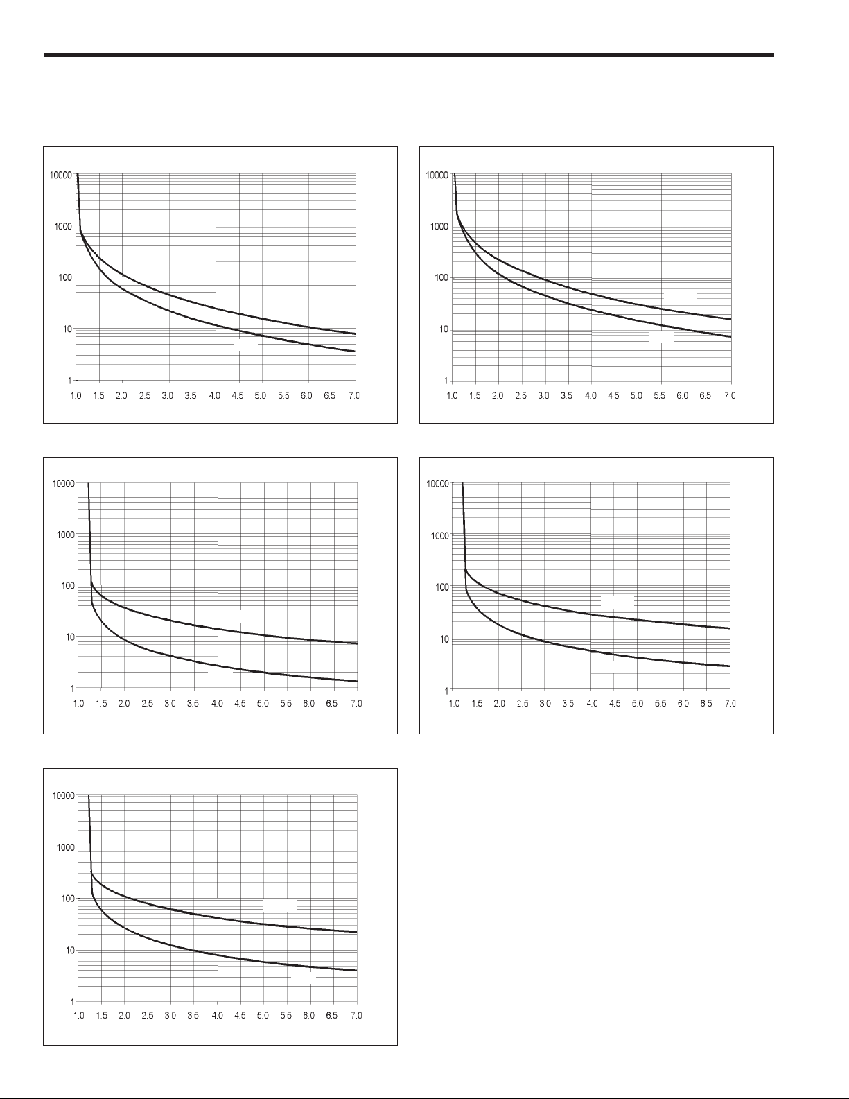
2-2. ASTAT®-IBP Plus, Thermal characteristics
The ASTAT-IBP Plus allows the user to select motor protection according IEC Class 10, 20 and NEMA 10, 20 or 30, selectable by "o" -overload- parameter
IEC Class 10 IEC Class 20
Sec. Sec.
COLD
COLD
HOT
Multiples of motor FLA Rating In
NEMA 10 NEMA 20
Sec.
COLD
HOT
Multiples of motor FLA Rating In
Sec.
HOT
Multiples of motor FLA Rating In
COLD
HOT
Multiples of motor FLA Rating In
NEMA 30
Sec.
Thermal memory:
If the control voltage is not removed, the unit has a cool down
characteristic. The time for cool down is 300 sec. after the
overload trip.
If the control voltage is removed after tripping, you must wait at
least 5 minutes before the unit can be restarted. See Section 4-10
for restart limitations.
COLD
HOT
Multiples of motor FLA Rating In
2-2
Page 9

3. Technical Specifications
3-1. ASTAT®-IBP Plus, General specifications
Voltage Ratings 3ph AC Systems Up to 600V, +10%, -15% for QI3xDP ASTAT-IBP
Plus series
Freq. Range 50/60 Hz Control range of 45-65 Hz
Control Control system Digital system with microcontroller
Specifications Starting ramp with progressive increase in voltage and
current limitation
Initial voltage (pedestal) % 30 - 95 U
Starting torque % 10 - 90 M
Kick start % 95 Un (90% M
Motor unit ratio (N) 0.4 - 1.2
Current limit (starting) 1 to 4.5 (Ir/In) Max 4.5 I
Acceleration ramp time s 1 to 45 (standard or linear ramp up)
Bypass Direct control of a bypass contactor
Brake time by ramp s 1 to 60 (1 to 60 in secondary ramp) adjustable independently of starting
ramp time (types: standard, pump control or linear ramp down)
Monitoring Motor current, line voltage (1), power, power factor and elapsed time
Running External control Start - Stop
Acceleration phase Adjustable time
Stop phase Power cut-off / Ramp / Pump control
Inputs / Outputs Inputs 4 digital optocoupled. Two fixed (Start , Stop), and 2 programmable (I3, I4)
1 Analog 0-5VDC for Tachogenerator input feedback
Outputs 2 Programmable relays (1r, 3r); 1 fixed relay (2r)
1 Analog 0-10VDC output for current metering
Protections Current limit Adjustable 1 to 4.5 (I
Overload IEC class 10 and 20 ; NEMA class 10, 20 and 30 all selectable
Cool-down time after
overload trip See Restart Times on page 4-10
Loss on input phase s Trip at 3
Thyristor short circuit ms Trip at 200
Heatsink overheating ms Trip at 200
Motor thermistor ms Trip at 200 if thermistor impedance > response value
Loss on output phase s Trip at 3
Stalled rotor ms Trip at 200
Supply frequency error Hz If f < 45 or f > 65, will not start
Overcurrent 100 to 150% In; trip time adjustable from 0 to 99 sec.
Undercurrent 0 to 99% In; trip time adjustable from 0 to 99 sec.
Overvoltage (1) 100 to 130% Un; trip time adjustable from 0 to 99 sec.
Undervoltage (1) 0 to 50% Un; trip time adjustable from 0 to 99 sec.
Error (CPU) ms 60
Memory 4 former errors
Long start time s 2 x ta (ta = acceleration ramp time)
n
direct start
direct start
), adjustable 0 to 999 ms
n
/I
) Max 4.5 I
r
n
n
I Actual measured motor current
I
m
I
n
I
r
L Current limit for starting Im/I
L
max
M
direct start
NI
SF Service factor
U
n
Abbreviations
Maximum starting current desired
Nominal motor nameplate FLA
ASTAT rated nameplate FLA
450/N
Full voltage starting torque
n/Ir
Full line voltage
r
Environmental Temperature °C0 to +55 (derate output current by 1.5% / °C above 40°C)
conditions Relative humidity % 95% without condensation
Maximum altitude m 3000 (derate output current by 1% / 100m above 1000m)
Mounting position Vertical
Protection Degree IP00, UL Open
Standards cUL, UL UL, cUL conforming to UL508
Conducted & radiated emissions Conforming IEC 947 -4-2, Class A
Electrostatic discharges Conforming to IEC 1000-4-2, level 3
Radioelectric interference Conforming to IEC 1000-4-6, level 3 and to IEC 1000-4-3, level 3
Immunity to fast trasients Conforming to IEC 1000-4-4, level 3
Immunity to Surge Voltage Conforming to IEC 1000-4-5, level 3
Note: (1) Monitors L1
(
3-1
Page 10

3. Technical Specifications
3-2. I/O terminal board specifications
Power I/O terminals
Terminal Function Description
1L1, 3L2, 5L3 Mains Input 3ph input voltage.
2T1, 4T2, 6T3 Motor output Output terminals to 3ph AC motor
TBA1, TBA2 Input Control Voltage 110/120V AC, +10%, -15%
Digital Inputs
Terminal Function Description
57 Common for digital inputs This is a common terminal for the digital input terminals specified below.
1 Run Run order. Command signal may be provided by one NO dry momentary contact to terminals 1 and 57.
2 Stop Stop order. Command signal may be provided by one NC dry momentary contact to terminals 2 and 57.
NOTE: Run/Stop permanent command is allowed linking 1-57 and using one dry NO contact to 2-57
terminals.
3 Programmable input I3 These two inputs are programmable. Can be assigned to the following internal functions:
4 Programmable input I4
-soft stop -linear ramp
-pump control -dual ramp selection
-kick start -local / remote control
Command signal should be provided by one NC dry contact to terminals 57-3 or terminals 57-4.
By switching this contact ON / OFF it is possible to enable or disable the assigned function.
Digital Outputs
Terminal Function Description
11, 12, 14 Programmable relay 1r
23, 24 Fixed relay 2r 23-24 = N.O. dry contact. This relay is assigned to function EOR for bypass contactor control
33, 34 Programmable relay 3r 33-34 = N.O. dry contact. This relay can be assigned to several internal output functions (page 3-5).
Analog I/O
Terminal Function Description
8 Analog input common (-) This is a common terminal for the analog input terminal number 7 and analog output terminal number 9.
7 TG feedback input (+) 0-5V analog input for speed feedback. It should be provided by a DC tacho-generator coupled to the motor.
9 Current output (+) 0-10V DC analog Output for current measurement purpose. (1 x I
Motor thermistor terminals
Terminal Function Description
5 , 6 Motor thermistor input This input allows a motor thermistor with a response value from 2.8 to 3.2KΩ , and a reset value from 0.75 to
11-12 = NC, 11-14 = N.O. dry contacts. This relay can be assigned to several internal output functions (p. 3-5).
As default assigned to function RUN
Common for all relay output contacts Maximum usage voltage: 380VAC (B300-UL)
Thermal current: 8A
AC-15 use: 220V / 3A, 380V / 1A
DC-15 use: 30V max/ 3.5A
This speed feedback signal is required when the "linear ramp" function is used.
= 2V DC output)
Load Impedance 10KΩ or higher.
1KΩ to control motor temperature.
When the motor thermistor is not used, a link must be used between terminals 5-6.
r
Communications
Terminal Function Description
SG, TD, RD Gr, Tx, Rx data RS232C, 3 wires, half duplex. Maximum cable length 3 meters (10 feet)
Asynchronous data transmission, 9600 Bauds, 1 bit start, 8 bits data, 2 bits stop, no parity.
3-2
Page 11
3. Technical Specifications
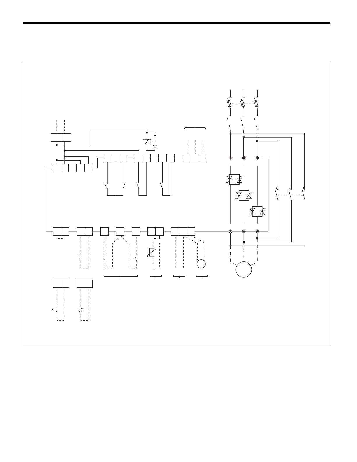
3-3. I/O wiring
ASTAT-IBP Plus terminal layout and wiring configuration is shown in the diagram below.
Control Voltage
110 / 120V AC
TBA2TBA1
M2
Bypass
Serial Comm.
RS232C
Tx
Gr
Rx
L1 L2 L3
A1A2 B1 B2
57 57 57 6 8
12
(Permanent Command)
(Command by push-buttons)
Start /Stop
57 57
1
Start Stop
12 11 14
1r 2r 3r
Programmable Relay Outputs
Programmable Inputs
I3 I4
23
3457
24
33
34
TD
+-
RDSG
9
-+
V
1 L1 3 L2 5 L3
2 T1 4 T2 6 T3
M
3 ~
M2
Bypass
2
Programmable
Inputs
Input
Motor Thermistor
Analog Input
Tacho feedback
0-10V
Analog Output
Notes: (1) Control and Mains wiring recommendations are given in chapter 5.
(2) The programmable inputs I3, I4 are not assigned to any function as default. Check pages 3-5 prior to using these
inputs.
(3) The programmable relay output is assigned to the following functions as default:
Relay (1r): RUN, (RUN status)
(4) Important: Use dry contacts only
3-3
Page 12
3. Technical Specifications
p
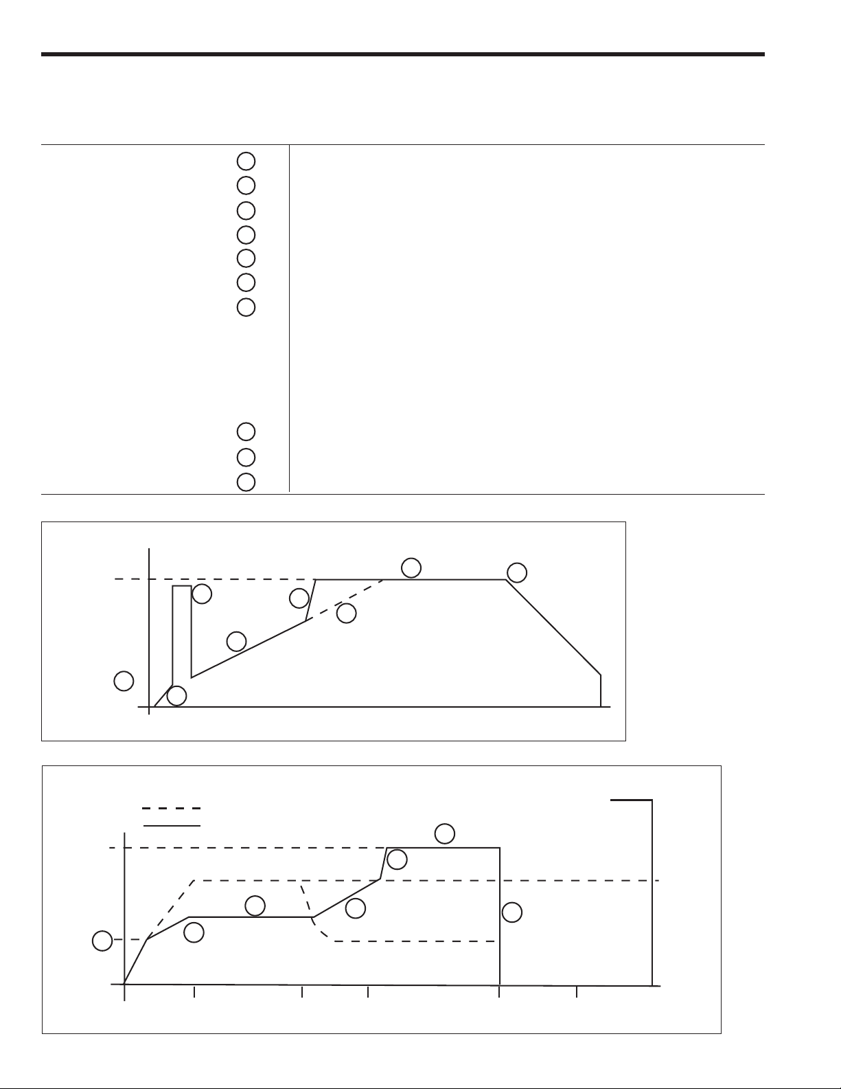
3-4. Operating modes
Operating Mode Key Description
Initial ramp
Initial voltage (pedestal)
Kick start
Acceleration ramp
Running mode
Soft stop mode
Current limit
Ramp continue
Stop mode
Starting by voltage ramp
U/Un
1a
1
2
3
4
5
6
7
8
9
5 main frequency cycles
30 to 95% Un (adjustable via initial torque setting T)
95% Un. Enabled by parameter "Pxxx" to ON, 0-999 ms (adjustable)
1-45 sec (adjustable). Dual ramp option.
Fast ramp (if motor is up to speed before end of normal ramp time)
Nominal voltage (bypass mode)
Deceleration ramp 1-60 sec (adjustable). Secondary ramp 1-60 sec.
Ramp down modes available are:
- Soft Stop -Voltage ramp down-. Enabled by "Sxxx" to ON
- Pump control. Selectable by "Sxxx" to ON and "Cxxx" to ON
- Linear ramp down (Tacho feedback needed)
Current limiting set point (100 to 450% x (Ir/In) Max 450% In)
Accelerating ramp (continuation of acceleration after motor amps drop below current limit)
Standard stopping (coast to rest)
100%
2
Starter
Output
Voltage (%)
1a
1
Starting by current limitation
Current to Motor
Out
100%
Starter
Output
Voltage (%)
1a
3
3
ut Voltage
7
5
6
4
8
Time
Motor Current
Max
450%
5
4
Current
Limit
8
9
Set Point
FLA
Ramp Current Limit
Ramp At Speed Coast Stop Time
(Voltage Hold)
3-4
Page 13

3. Technical specifications
3-5. Programmable inputs and outputs
Programmable inputs and functions
The ASTAT-IBP Plus functions such as soft stop, kick start, etc., can be enabled (ON) or disabled (OFF) and set in their dedicated parameters by
using the keypad. Most of these functions can be enabled or disabled remotely as well, through the programmable inputs I3 or I4 (terminals 3-57
and 4-57).
Function Parameter
Soft Stop
Pump Control
Kick Start
Linear Ramp
Dual Motor
Remote Control
S xxx
C xxx
P xxx
D xxx
A xxx
X xxx
More than one function can be enabled in the ASTAT-IBP Plus, either by the keypad or through the programmable inputs I3 and I4, but there are
some functions which may not work as expected during stopping, such as when they are simultaneously enabled. When two or more of the below
functions are simultaneously enabled, the priority is defined in the following table:
Set Value
_OFF
_ON
_I3
_I4
<Remarks>
The function is permanently disabled
The function is permanently enabled
The status of the function depends upon I3 input
The status of the function depends upon I4 input
NOTE: One programmable input may enable or
disable more than one function
Condition Action
○○○○○○
○○○○○○
Linear Ramp (S, D=ON) aa
Soft Stop (S=ON) a b
○○○○○○○○
○○○○○○○○
a The unit stops by Linear Ramp
b The unit stops by Pump Control
Pump Control (S, C=ON) a b
C=ON)
Pump Control (S,
Soft Stop (S=ON)
Linear Ramp (S, D=ON)
Programmable relay outputs
The ASTAT-IBP Plus includes two programmable relays 1r and 3r (dry contacts). ASTAT terminals are 11-12-14 and 33-34.
These relays can be assigned to several functions, as shown below.
Relay N#
Relay 1r
Relay 3r
Parameter
1rxx
3rxx
Set Value
22
23
24
25
27
28
29
30
Fault Detects ASTAT-IBP Plus fault status
Undervoltage (1) Detects limit set in parameter UVxx
Overvoltage (1) Detects limit set in parameter OVxx
RUN Detects ASTAT-IBP Plus run status
Undercurrent Detects limit set in parameter UCxx
Overcurrent Detects limit set in parameter OCxx
Disabled Disables the relay function
Future use
<Remarks>
Relay 2r has a fixed value of 20 (terminals 23-24) for end of ramp (EOR) Bypass Control.
Note: (1) Monitors L1
3-5
Page 14

4-1. Keypad and display description
1
2
4. Programming
C / V
Display
Display Structure
Function code
FVVV
Keypad
C / V
1
Displays monitoring, status indications, error messages and function set values
FVVV Status code
ON Equipment is
Data
2
SELECTION
Use with or to select the parameter or function code
to be displayed and/or modified
STOP Stop
LOCK Remote stop
PULS Kick start
RAMP Acceleration ramp
FULL Full conduction
SOFT Soft stop
PUMP Pump control
TACH Linear ramp (tacho)
Allows setting of parameters and functions
connected
to main supply
(equipment is ON)
FVVV Error code
E010 Frequency out of range
E011 Overload trip
E013 Loss of synchronism
E014 Phase U scr
E015 Phase V scr
E016 Phase W scr
E017
E018 Motor thermistor
E019 Phase U lost
E020 Phase V lost
E021 Phase W lost
E022 Stalled rotor
E023 Internal error
E025 Long start time
E027 Lock-out
E028 Undervoltage
E029 Overvoltage
E030 Undercurrent
E031 Overcurrent
Heatsink overtemperature
SEARCH / ADJUSTMENT
Decreases the value of the selected parameter
F F/V V V Function code (*)
Mx x x Motor current
vxxx Software version
. .
. .
PFxx Power factor
. .
. .
Lxxx Current limit
Txxx Starting torque
axxx Ramp up time
dxxx Ramp down time
Sxx x Soft stop selection
..
. .
LKxx Lock out
..
. .
(*)These are examples. Full details in
sections 4-2, 4-3, 4-4, 4-5 and 4-6
SEARCH / ADJUSTMENT
Increases the value of the selected parameter
ENTER / SAVE
- Introduces the new parameter value into memory
- Updates the selected parameter value with the
displayed value
4-1
Page 15

4. Programming
4-2. Parameter block configuration
Mode Selection
The ASTAT-IBP Plus includes a large number of parameters which are divided
into four blocks: Monitor, Calibration, Basic and Advanced. The parameters of
each group can be displayed or skipped according to the selection done in
parameter "G".
The monitor parameters are always displayed regardless of the mode selected
Monitoring
Parameters
G ALL
G CAL
Calibration
Parameters
Settings in parameter "G" GCAL The Calibration parameters are displayed
GBAS The Basic parameters are displayed
G BAS
Basic
Parameters
GADV The Advanced parameters are displayed
GALL All parameters are displayed
G ADV
Advanced
Parameters
Searching and Setting Parameters
The ASTAT-IBP Plus displays the parameters sequentially while depressing the key and pushing repeatedly or keys. Proceed in this way
until the parameter "G" is displayed.
There is a quick way to search automatically the parameter "G" by pressing and Keys. "Gxxx" will be shown on the display.
Once the parameter "G" is displayed, choose the value desired by pressing or Keys. The display will sequence "GBAS", "GCAL", "GADV" and
"GALL" values repeatedly. The actual value displayed can be stored in a temporal memory buffer by pressing key.
Values stored in the temporal memory are lost upon control power loss, unless saved in the permanent E2PROM memory through parameter "W".
Additional instructions are given on page 4-9.
The above is an example given for parameter "G", but all ASTAT-IBP Plus parameters can be modified from its default factory value in a similar way.
C / V
C / V
Parameter layout
Monitor parameters
Status
C / V
+
Shown automatically ON, STOP, LOCK, PULS, ...
M
Motor current
v
Software version
Line voltage
V
Line power factor
PF
Line power
w
E
Elapsed time
e
Fault history buffer
Password
K
E2PROM writing
W
G
Parameter block selector
GBAS
12
GADV GALL
(see page 4-4)
e0, e1, e2, e3
GCAL
Calibration parameters
U
Line voltage
t
Voltage calibration
Unit frame
UF
Current calibration
m
N
Motor unit ratio
o
Overload protection
Service factor
f
100-600
0-690
K,L , ... ,S
0-1300
40-120
0, N1, N2, N3,C1,C2
100-130
4-2
Page 16

4. Programming
1
Basic Parameters
L
Current limit
(starting)
T
Starting torque
Ramp up
a
time
d
Ramp down time
p
Kick start
Soft stop switch
S
Pump control switch
C
Pump curve selection
ST
starting
Pump curve selection
SP
stopping
Kick start switch
P
(1) 100-450 (Ir/In) ; 450 max.
Unit
%
%
sec.
sec.
ms
Range
100-450 (1)
010-090
01-45
01-60
000-999
OFF, ON, I3, I4
OFF, ON, I3, I4
00-03
00-05
OFF, ON, I3, I4
2
Advanced Parameters
LK
Lock-out
R
E2PROM reading
Factory settings
Q
UV
Undervoltage
Undervoltage trip time
uv
Overvoltage
OV
ov
Overvoltage trip time
UC
Undercurrent
uc
Undercurrent trip time
Overcurrent
OC
oc
Overcurrent trip time
2a
Secondary ramp up
2d
Secondary ramp down
Secondary starting torque
2t
D
Tacho control switch
Unit
minutes
%
sec.
%
sec.
%
sec.
%
sec.
sec.
sec.
%
Range
00-45
ON, OFF
ON, OFF
00-50
00-99
00-30
00-99
00-99
00-99
00-50
00-99
01-45
01-60
10-90
ON, OFF, I3, I4
Dual motor switch
A
Remote control switch
X
Comm protocol selection
XP
Station number
s
1r
Output relay 1r
2r
Output relay 2r
Output relay 3r
3r
OFF, ON, I3, I4
OFF, ON, I3, I4
00-02
001-247
22-30
20
21, 22-30
4-3
Page 17

4-3. Monitor block parameters
4. Programming
Display
ON
M xxx
v xxx
V xxx
PFxx
w xxx
E xxx
Function
Status
Motor current
Software version
Main source voltage (1)
Power factor
Line power
Elapsed time
Default Range Unit
ON
ON
STOP
LOCK
PULS
RAMP
FULL
SOFT
PUMP
TACH
000-999
1.0-9.9
-
-
00-99
-
-
-
-
-
-
-
-
-
-
-
A
kA
%
-
V
%
kW
Hrs
Description
Switch on time. Equipment is connected to main supply
Stop
Remote control through serial port.
Kick start
Acceleration ramp
Full conduction
Soft stop
Pump control
Linear ramp (tacho feedback needed)
Displays motor current in Amps.
Current higher than 999A is displayed in kA.
If parameter UFxx is not calibrated, the motor current
is displayed in % In.
xxx = Version number
Displays line voltage in Volts.
Displays line Power Factor
Displays Line Power
Displays RUN time in Hours (x 1000)
e xxx
K xxx
W xxx
G xxx
Note: (1) Monitors L1
Error trace buffer
Password
E2PROM writing
Parameter display
selection
K 000
W OFF
G BAS
e0xx-e3xx
000-999
ON, OFF
CAL, BAS, ADV,
ALL
-
Saves the last four errors:
e0xx: Fault 1 -Latest fault- xx: Fault code error
e1xx: Fault 2
e2xx: Fault 3
e3xx: Fault 4
-
= 69 allows E2PROM writing operation
= 10 Key lock enabled
= 20 Key lock disabled
-
Saves the unit current parameters to the E2PROM.
This rewrites the last values saved. (Password 69
required)
-
CAL: Displays Calibration Parameters
BAS: Displays Basic Parameters
ADV: Displays Advanced Parameters
ALL: Displays All parameters
4-4
Page 18

4-4. Calibration block parameters -CAL-
4. Programming
Display
U xxx
t xxx
UF x
m xxx
N xxx
o xxx
Function
Line voltage setting
Voltage calibration
Unit frame
Current calibration
Motor rated current
Overload protection
Default Range Unit
U 480
t 480
UF 0
m 000
N 100
o N2
200-600
000-690
K, L, Y, M, Z, N,
P, Q, R, S
000-1300
040-120
OFF
N1, N2, N3,
C1, C2
Description
Line Voltage from 200 to 600V. Set rated value.
V
Setting of this parameter allows better accuracy in
V
monitoring and voltage protections (see the voltage
calibration procedure). (1)
Unit frame rating (K,L,...S).
Setting “0” disables current calibration.
Setting of this parameter allows better accuracy in
A
monitoring and current protections (see the current
calibration procedure).
100 x In/I
%
When this parameter is adjusted at a value higher than
105% the overload protection curve is automatically
adjusted to Class 10. "C1" if Cx was selected, or to
NEMA 20 "N2" if Nx was selected.
Selects either the following overload curves:
OFF: Overload protection disabled
N1: NEMA 10
N2: NEMA 20
N3: NEMA 30 (not available if N ≥ 105)
C1: Class 10
C2: Class 20 (not available if N ≥ 105)
r
(external overload relay must be used)
f xxx
Note: (1) Monitors L1
Service factor
f 100
100-130
Motor service factor.
%
Voltage calibration procedure
When the ASTAT-IBP Plus is installed on site for the first time or after the logic printed circuit board is replaced, the voltage measurements will have
an accuracy of ±10%. To improve the voltage measurement accuracy up to ±3%, proceed as follows:
1. Turn the ASTAT-IBP Plus ON and measure the RMS voltage on phases 1L1-3L2 using a calibrated voltmeter.
2. Search for the parameter “txxx”, set the measured voltage, and save this value by depressing the enter key. It is not necessary to save
this to the E2PROM, as the ASTAT-IBP Plus does this automatically. NOTE: Set the actual, measured voltage while the ASTAT-IBP Plus is
ON. DO NOT enter the motor nameplate voltage rating.
3. Once the ASTAT-IBP Plus has been calibrated, this operation does not need to be repeated unless the logic printed circuit board has
been replaced or the ASTAT-IBP Plus has been installed into a new application. NOTE: The parameter “txxx” will show the latest
calibration entry, which may differ from the actual voltage value.
Current calibration procedure
When the ASTAT-IBP Plus is installed on site for the first time or after the logic printed circuit board is replaced, the current measurements will have
an accuracy of ±10%. The internal electronic overload protection is also affected by this procedure. To improve the current measurement accuracy
up to ±3% and to improve the accuracy of the motor overload protection, proceed as follows:
1. Search for the parameter “UF_ x” and enter the correct ASTAT-IBP Plus frame type letter (“F”,”G”,”H”,..etc.).
2. Start the motor and measure the rms motor current using a calibrated ammeter. This measurement should be done at full load and full
speed and after the motor current has stabilized.
3. Search for the parameter “mxxx”, set the measured current and save this value by depressing the enter key. It is not necessary to save
this to the E2PROM, as the ASTAT-IBP Plus does this automatically. NOTE: Set the actual rms measured current while motor is running
at full speed and under full load. DO NOT enter the motor nameplate current rating.
Once the ASTAT-IBP Plus has been calibrated, this operation does not need to be repeated unless the logic printed circuit board has been replaced
or the ASTAT-IBP Plus has been installed into a new application. NOTE: The parameter “mxxx” will show the latest entry, which may differ from the
actual current value.
4-5
Page 19

4-5. Basic block parameters. -BAS-
4-5-1. Basic Functions
4. Programming
Display
L xxx
T xx
a xx
d xxx
p xxx
Note: (1) Parameter "p" is disabled while "C" is ON.
Function
Current limit (starting)
Starting torque
Ramp up time
Ramp down time
Kick start (1)
4-5-2. Programmable basic functions
Default Range Unit
L 400
t 25
a 15
d 020
p 000
100 - L
10-90
01-45
01-60
000-999
max
%
%
sec.
sec.
ms.
Description
Sets Device current limit. Sets motor starting current
limit if parameter "N" is properly adjusted.
The maximum range setting is automatically calculated
by the unit according the following expression:
L
max
Sets the initial voltage applied to the motor.
Sets Voltage ramp up time. Motor acceleration time
will depend of load conditions.
Sets Voltage ramp down time. Motor deceleration
time will depend of load conditions.
Enabled only if the parameter "Sxxx" is ON.
During the time adjusted, provides 95% of full voltage to
motor at starting time. Useful for high static-friction loads
Enabled only if the parameter "Pxxx" is ON.
Ir
= 450 ( ); Max 450
In
Display
S xxx
C xxx
STXX
SPXX
P xxx
Function
Soft stop selector
Pump control selector
Pump curve selection
at starting phase
Pump curve selection
at stopping phase
Notes:
- Curve 0 (both ST00, SP00): Standard voltage ramp up -starting- and ramp down -soft stop-
- Curve 1 (both ST01, SP01): Pump Algorithm based on estimated average PF -power factor- , with large sampling period.
- Curve 2 (both ST02, SP02): Pump Algorithm based on instantaneous PF with short sampling period.
- Curve 3 (both ST03, SP03): Pump Algorithm based on estimated average PF with short sampling period. Application:
- Curve 4 (SP04): Same as Curve 3, but with higher accuracy on PF average estimation. Application: high head
- Curve 5 (SP05): Pump Algorithm based on former ASTAT-CD.
Kick start selector
Default Range
S OFF
C OFF
ST02
SP02
P OFF
OFF, ON, I3, I4
OFF, ON, I3, I4
low pressure system/low flow rate change.
pressure/low flow rate change.
OFF, ON, I3, I4
00-03
00-05
Description
Enables or disables all modes of Soft stop.
Enables the Pump control function. Usefull to limit fluid hammering.
The parameter "Sxxx" must also be enabled.
NOTE: Parameter "p" is disabled while "C" is ON.
Choice of various pump control algorithms for starting:
0: Voltage ramp up 01-03: Various pump algorithms
Choice of various pump control algorithms for stopping phase:
0: Voltage ramp down 01-05: Various pump algorithms
Enables or disables the Kick start function.
If Pump control function “C” is enabled, both Kick start and DC Brake
functions are internally disabled.
z xxx
By-pass selector
z ON
—
4-6
This function provides control of an external by-pass contactor,
significantly lowering heating losses and eliminating harmonics.
The programmable relay output 2r is assigned to this function, and
must be used to control the external by-pass contactor.
Page 20

4-6. Advanced block parameters -ADV-
4-6-1. Advanced functions
4. Programming
Display
LKxx
R xxx
Q xxx
UVxx
uvxx
OVxx
ovxx
UCxx
ucxx
Function
Lock-out
E2PROM reading
Factory settings
Undervoltage
Undervoltage trip time
Overvoltage
Overvoltage trip time
Undercurrent
Undercurrent trip time
Default Range Unit
LK05
R OFF
Q OFF
UV00
uv20
OV00
ov20
UC00
uc20
00-45
ON, OFF
ON, OFF
00-50
00-99
00-30
00-99
00-99
00-99
min.
-
-
%
sec.
%
sec.
%
sec.
Description
Sets time between consecutive starts. Setting "0" disables
this function.
Loads the parameters from the E2PROM to the temporal
buffer.
Loads default factory settings to the temporal buffer.
Resave to E2PROM if default settings are desired.
The unit trips if the line voltage on Leg L1 decreases below
the percentage set. Setting “0” disables this protection.
NOTE: Perform voltage calibration procedure on page
4-5 before enabling this protection.
Delay trip time.
The unit trips if the line voltage on Leg L1 increases above
the percentage set. Setting “0” disables this protection.
NOTE: Perform voltage calibration procedure on page
4-5 before enabling this protection.
Delay trip time.
The unit trips if the current decreases below the percentage
set. Setting “0” disables this protection.
NOTE: Perform current calibration procedure on page
4-5 before enabling this protection.
Delay trip time.
OCxx
ocxx
2axx
2dxx
2Txx
Overcurrent
Overcurrent trip time
Dual Ramp Up
Dual Ramp Down
Dual StartingTorque
OC00
oc20
2a15
2d20
2T25
4-6-2. Programmable advanced functions
Display
D xxx
A xxx
X xxx
XPxx
Function
Linear ramp
Dual motor selector
Remote control selector
Comunication protocol
Default Range
D OFF
A OFF
X OFF
XP00
00-50
00-99
01-45
01-60
10-90
OFF, ON, I3, I4
OFF, ON, I3, I4
OFF, ON, I3, I4
00-02
%
The unit trips if the current increases above the percentage
set. Setting “0” disables this protection.
NOTE: Perform current calibration procedure on page
sec.
%
%
%
Delay trip time.
These are a secondary set of ramp up, ramp down and
starting torque parameters, which take over the primary
"d" and "T" when the programmable function “A” is enabled.
4-5 before enabling this protection.
"a",
Description
This function provides linear acceleration and deceleration ramps in a
wider range of load conditions using tachogenerator feedback.
A DC Tacho-Generator coupled to motor must be used to provide an
analog signal feedback of 0-5VDC to terminals 7 and 8.
This function allows dual motor control settings of acceleration,
deceleration and starting torque, and is useful to start or stop a motor
in diferent load conditions.
When this function is enabled, the parameters 2a, 2d and 2T take over
the parameters a, d and T. It allows dual motor control settings.
Allows serial communication control by SG, TD and RD terminals.
Check Appendix section for more details.
Sets serial communications protocol.
0: ASCII 1: Future use
2: Future use
s xxx
Station number
s 001
001-247
4-7
ASCII protocol allows a maximum of 90 stations only.
Page 21

4-6-3. Relay output functions
4. Programming
FunctionDisplay
1rxx
2rxx
3rxx
The programmable relays can be set to the functions shown in the following table:
Output relay 1r
Output relay 2r
Output relay 3r
Range
20
22
23
24
25
27
28
29
30
Function
EOR
FAULT
Undervoltage
Overvoltage
RUN
Undercurrent
Overcurrent
Disabled
Future use
Default Range
1r25
(RUN)
2r20
(EOR)
3r22
Remarks
Detects end of voltage ramp. This function may only be assigned to relay 2r-
Detects unit Fault status. ON is normal status and switches OFF if a fault occurs
Detects Undervoltage according limit adjusted in function “UV”
Detects Overvoltage according limit adjusted in function “OV”
Detects unit RUN status
Detects Undercurrent according limit adjusted in function “UC”
Detects Overcurrent limits as adjusted in function “OC”
Disables the relay function
22-30
20
22-30
Description
This is a programmable relay with one NO / NC dry contact to
ASTAT-IBP Plus terminals 11-12-14.
This is a non-programmable relay with one NO dry contact to
ASTAT-IBP Plus terminals 23-24.
This relay is assigned to by-pass control.
This is a programmable relay with one NO dry contact to ASTATIBP Plus's terminals 33-34.
4-7. Application and basic settings
Different applications will require different characteristics and settings for the ASTAT-IBP Plus. The table below lists typical settings for
various applications.
Settings (X X X)
Display
Parameters (1)
Nominal motor current N x x x 100
Current limit L x x x 400 375 400
Initial torque T x x x 025 030 035 020 020
Acceleration ramp time a x x x 015 015 030 030 015
Deceleration ramp time d x x x 020 040
Kick start time(2) p x x x 000 100
Soft stop S x x x OFF ON
Pump control C x x x OFF ON
Pump curve starting S T x x 02 02
Pump curve stopping S P x x 02 02
Kick start P x x x OFF ON
Parameter
Factory
Default
Compressor Mill Fan
Machine
Tool
Pump
Control
Overload trip curve(3) o x x x ooN2 ooN2 ooN2 ooC2 ooC1 ooC1
Service Factor(3) f x x x 100
Notes: (1) = GBAS Block Parameters unless noted(2)(3)
(2) = Parameter “p” is disabled while “C” is ON.
(3) = GCAL Block Parameters
4-8
Page 22

4-8. Saving parameters to E2PROM
Advance the display to K000 with
the C/V and up arrow button.
Change the parameter to K069 with
the up arrow button.
With K069 displayed, press the
enter button.
4. Programming
Display will show SET momentarily
and then display K ON.
Advance the display to WOFF with
the C/V and up arrow button.
Change parameter to W ON by using
the up arrow button.
With W ON displayed, press the
enter button.
Display the show SET momentarily
and then display WOFF.
4-9
Page 23

4. Programming
4-9. Lockout
The number of starts per hour that the ASTAT-IBP Plus can initiate is limited and depends on the starting current and the ramp time, as
listed below. The ASTAT-IBP Plus has a lockout feature that is designed to protect the SCRs between starts. This parameter should be
set before operating the ASTAT-IBP Plus. The lockout setting range is 0-45 minutes between starts. After starting a motor, the ASTATIBP Plus goes into lockout mode for the period set for the LKXX parameter. If a consecutive soft start is attempted within the time set for
the LKXX parameter, error code E027 will appear on the display. See Table 7 for the appropriate value to program this parameter.
Note: If soft stop is enabled, the lockout times listed should be increased by 50%.
Note: Si l’arrêt progressif (Soft Stop) a été choisi, les temps de verrouiller hors devraient être augmentés de 50%.
Starting
Power % of
Unit Duty Frame
Size Cycle Rating Amps
K Std 300% 165 6 10 15 4 30 2 30 2
Hvy 450% 248 1 45 8 8 20 3 30 2
L Std 300% 204 1 45 8 5 20 3 30 2
Hvy 450% 306 ————8 7 12 5
Y Std 300% 240 1 45 8 7 20 3 30 2
Hvy 450% 360 1 ———————
M Std 300% 315 6 10 12 5 28 3 30 2
Hvy 450% 473 2 30 8 8 15 4 30 2
Z Std 300% 390 4 15 10 6 20 3 30 2
Hvy 450% 585 1 45 6 10 10 6 30 2
N Std 300% 468 2 30 8 8 15 4 30 2
Hvy 450% 702 — — 4 15 10 6 20 3
P Std 300% 576 6 10 14 4 30 2 30 2
Hvy 450% 864 2 30 4 15 10 6 20 3
Q Std 300% 744 4 15 9 6 24 3 30 2
Hvy 450% 1116 ———— 6 1012 5
R Std 300% 906 2 30 4 15 10 6 25 3
Hvy 450% 1359 —————— 6 10
S Std 300% 1083 1 45 3 20 6 7 12 5
Max 1161 1 45 3 20 8 7 12 5
30 sec. start
Starts between
hour min.
LK time
per starts,
20 sec. start
Starts between
per starts,
hour min.
LK time
10 sec. start
LK time
Starts between
per starts,
hour min.
5 sec. start
Starts between
per starts,
hour min.
LK time
NOTE: If control power is lost, lockout time resets to five minutes.
ATTENTION: Si la puissance de contrôle est perdue, le temps du relais de verrouillage se réarmeá cinq-minutes.
4-10
Page 24

5. Installation
5-1. Equipment installation
CAUTION! DISCONNECT POWER BEFORE INSTALLING OR SERVICING
ONLY SPECIALIZED PERSONNEL SHOULD INSTALL THE EQUIPMENT AND ONLY
AFTER HAVING READ THIS USER'S GUIDE.
THE USER IS RESPONSIBLE FOR ANY PHYSICAL INJURY OR MATERIAL DAMAGE
RESULTING FROM MISHANDLING THE EQUIPMENT.
5-2. General
Terminal Connections
Use minimum of 75°C copper wire only for connections to ASTAT-IBP Plus terminals. The minimum wire size must conform to the 75°C
table according to applicable electrical codes. Tighten connections to the torque values given below. Supply conductors should have,
as a minimum, the same cross section as a full voltage starter.
Catalog Numbers Wire Range Torque, in-lb
CI2K, QI2L, QI2Y, QI2M, QI2Z, QI2N #14-#2 AWG 125
QI2P, QI2Q #6 AWG-350 kcmil 275
QI2R, QI2S #2 AWG-2x250 kcmil (or 1x600 kcmil) 550
Signal Wiring
Signal wiring should be no longer than 18 feet (up to 80 feet when
using shield cable). It must be separated from power wires (line,
motor, commands relays, etc.) by at least four inches and, if they
Coil Surge Suppression
Relays and contactors located in the same housing as the equipment
should have an RC suppressor parallel to the coil (or a reverse
diode, if controlled by DC).
cross, they should do so at a 90° angle.
10 cm 8 cm
SIGNAL
POWER
CORRECT INCORRECT
A A C D D C
Power Factor Capacitors
Do not install capacitors to correct the power factor between equipment output and motor.
Transformers
If the equipment is fed by a line transformer, its rated power should be at least 1.5 times, but less than 10 times, higher than equipment supply.
Environment
When installing equipment, keep the following points in mind:
- The equipment should be installed vertically and hang over a
platform or bars. The vertical position is essential for proper cool air
circulation.
- Environmental conditions are in accordance with the following
ranges and maximum values:
- Operating temperature: 0ºC to +55ºC
- Relative humidity (without condensation): 95%
- Maximum altitude: 3000m
Reduce rating by 1.5% / ºC from 40ºC and 1% / 100m from 1000m
- Do not install equipment in environments containing explosive or
flammable gases, or near important heat sources.
- Equipment should be well ventilated, with minimum keeping
clearances as indicated in the illustration.
- When equipment is to be mounted on a platform subject to strong
vibrations, there should be an elastic base to protect the equipment.
- When mounted in an enclosure, the temperature inside the enclosure
must be kept within the range of 0-45°C (32-113°F).
50mm 50mm
150mm
ASTAT
100mm
5-1
Page 25

5. Installation
5-3. Branch circuit protection
ASTAT-IBP Plus starters are suitable for use on a circuit capable of delivering not more than the rms symmetrical amperes listed in the
tables below when used with the listed circuit protection.
Note: When ASTAT-IBP Plus reduced-voltage starters are used in conjunction with semiconductor fuses, Type 2 coordination to IEC 947-4
is attained. These fuses are recommended for best overall short-circuit protection. The semiconductor fuses specified in Table below may
provide branch-circuit protection. Refer to applicable local electrical codes.
Note:
Lorsque des démarreurs à voltage réduit ASTAT-IBP sont utilisés en conjonction avec des fusibles seni-conducteurs, on obtient une coordination de type 2
selon IEC 947-4. Ces fusibles sont recommandés pour une meilleure protection d’ensemble contre les court-circuits. Les fusibles semi-conducteurs spécifiés au
tableau 11 peuvent fournir une protection de dérivation d’un circuit. Veuillez vous reférer aux codes électriques locaux s’y appliquant.
Circuit Breaker Fuse
Catalog
Number
QI3KDP 100A 25kA 10kA 100A 100kA
QI3LDP 100A 25kA 10kA 100A 100kA
QI3YDP 100A 25kA 10kA 100A 100kA
QI3MDP 150A 25kA (1) 10kA 400A 100kA
QI3ZDP 225A 25kA (1) 10kA 400A 100kA
QI3NDP 225A 25kA (1) 10kA 400A 100kA
QI3PDP 225A 25kA (1) 10kA 400A 100kA
QI3QDP 400A 25kA (1) 10kA 400A 100kA
QI3RDP 600A 25kA (1) 18kA 600A 100kA
QI3SDP 600A 25kA (1) 18kA 600A 100kA
Max. Circuit
Breaker Size 208/240/480V 600V
Max. Short Circuit Current Max. Max. Short Circuit
Class J Current
Fuse Size 208/230/480/600V
Notes: (1) = Starters size M,Z,N,P,Q,R,S have a branch circuit rating of 65kA when used with circuit breakers that are rated 65kA or higher.
Semiconductor Protection
Gould-Shawmut Semiconductor Fuses
208/240/480V 208/240/480/600V Max. Short
Catalog Std Heavy Fuse Std Heavy Fuse Circuit
Number Duty Duty Type Duty Duty Type Current
QI3KDP 125 A 175 A A50QS 125 A 150 A A70QS 100kA
QI3LDP 150 A — A50QS 150 A — A70QS 100kA
QI3YDP 175 A — A50QS 175 A — A70QS 100kA
QI3MDP 225 A 350 A A50QS 225 A 250 A A70QS 100kA
QI3ZDP 300 A 400 A A50QS 300 A 400 A A70QS 100kA
QI3NDP 350 A 450 A A50QS 350 A 450 A A70QS 100kA
QI3PDP 400 A 600 A A50QS 400 A 450 A A70QS 100kA
QI3QDP 500 A — A50QS 500 A — A70QS 100kA
QI3RDP 600 A — A50QS 600 A — A70QS 100kA
QI3SDP 700A 1000A A50QS 700A 800A A70QS 100kA
5-2
Page 26

5-4. Start-up
5. Installation
- Make sure equipment wiring corresponds
to one of the recommended routing
diagrams or equivalent.
- Make sure the control wire harness corresponds to the control voltage used.
- Set the Motor/Unit ratio (N)
I
n
N x x x ; x x x =
I
x 100
r
- Set starting parameters as needed:
L x x x = 450/N
I
m
L x x x =
x 100
I
n
- Set overload trip curve as needed:
- If the motor has thermal protection sensor, remove the link between
terminals 5 and 6 prior to wiring the sensor.
1. Enter the motor nameplate full load amperes: (In) ________
2. Enter the ASTAT-IBP Plus nameplate full load amperes: (Ir) ________
3. Divide Line 1 by Line 2 and multiply by 100. This is your N parameter value. ________
4. Enter the facility or installation maximum allowable amperes: ________
5. Divide Line 4 by Line 1 and multiply by 100. This is your maximum allowable
L parameter value governed by facility limitations. ________
6. Divide 450 by Line 3 and multiply by 100. If the result is greater than 450, enter 450.
This is you maximum allowable L parameter value governed by ASTAT-IBP Plus limitations. __________
7. Enter the value of Line 5 or Line 6, whichever is lower. This is your maximum
allowable L parameter value. ________
Starting torque T _ x x T _ 2 5
Acceleration ramp time a x x x a _ 1 5
Kickstart P ON/OFF/I3/I4 P OFF
Kickstart time p x x x (if P enabled) p 0 0 0
Current limit L x x x L 4 0 0
oxxx ; xx x OFF =
disabled (extermal overload relay must be used
C1/C2 = IEC Class 10 or Class 20
N1/N2/N3 = Nema 10, 20 or 30
Factory setting
N 1 0 0
Factory setting
Factory setting
o N 2
- Set stopping parameters as needed:
Factory setting
Soft stop S ON/OFF/I3/I4 S OFF
Deceleration ramp time d x x x d _ 2 0
If you change the default configuration and
wish to keep it, remember to rewrite the
parameters in E2PROM as follows :
(See page 4-9 for details)
- Set parameter K to ON (ON = 69 + )
- Set parameter W to ON
- Press (parameter W is set to OFF automatically)
- Send run command to equipment and make sure that operation is correct.
5-5. Troubleshooting
Symptom or Error & (Error Code) Possible Cause Measures to be taken
Display OFF
Equipment does not respond to
STOP / START controls
No control voltage
Main breaker tripped or fuse blown
F1 fuse blown on power supply PCB
Bad connection of flat ribbon wire joining
power supply PCB to control PCB
F2 fuse blown on power supply PCB
Check wire harness and control voltage
Check and change, page 6-12
Verify connectors
Check power supply board and logic board
for 5VDC. Use a DC voltmeter on the
power supply board, (-) lead of voltmeter
on the top lead of C6 (located next to the
black heatsink on the right edge of the
power supply board) and the (+) lead of
voltmeter on top lead of Diode AD21 or
R25 (located on the upper right corner of
the power supply board.)
Check and change, page 6-12
5-3
Page 27

5. Installation
V
Symptom or Error & (Error Code) Possible Cause Measures to be taken
Frequency error
(admits 45Hz ≤ f main ≤ 65Hz) (Ex10)
Overload trip (Ex11)
Synchronism loss (Ex13)
Phase A, B, C thyristor (Ex14)
(Ex15)
(Ex16)
Heatsink thermostat (Ex17)
Motor thermistor (Ex18)
Phase A, B, C loss (Ex19)
(Ex20)
(Ex21)
Stalled rotor (Ex22)
Internal error (Ex23)
No 1L1 phase or frequence is out of range
Excessive load or excessive current during
starting
Phase 1L1 lost
Short circuited thyristor
No output phases
Heatsink thermostat tripped by overheating
or defective
Motor thermistor tripped by overheating or
defective
No input / output phases
Defective thyristor or ribbon wire harness
loose or defective
Equipment detected stalled motor rotor
Micro-controller malfunction
Check 1L1 phase and/or mains frequence
Verify overload conditions during starting time and
steady state.
Check settings in parameters "Nxxx", "Lxxx", and "oxxx"
Check 1L1 phase
Check thyristor module
Check ground connections and voltage to ground
Poor ribbon cable connection
Check 2T1, 4T2 and 6T3 phases
Check for adequate ventilation
Check thermostat and wiring
Check thermistor and wiring, if no thermistor
terminal 5 and 6 must be jumpered
Check power wire harness for 1L1, 3L2,
5L3, 2T1, 4T2 and 6T3
Verify gate and cathode wire
harness. Verify thyristors
Restart equipment and check for an appreciable
loss in motor speed at any time
Check IC1 and IC8 are correctly inserted in their sockets.
Check for noise on control voltage power or line
Long start time (Ex25)
Current limit condition present more than
2 x ta sec. or 240 sec.
(ta = acceleration ramp time)
Lock-out (Ex27)
The time between startings is less that the
adjusted in parameter "LKxx"
Undervoltage (Ex28)
Overvoltage (Ex29)
Undercurrent (Ex30)
Overcurrent (Ex31)
The line voltage exceeds of limit set in
parameters "UVxx" or "OVxx"
The motor current exceeds of limit set in
parameters "UCxx" or "OCxx"
5-6. Thyristor check
Shortcircuit
Use a testing lamp to check the defective power module between input and output phases.
If the lamp goes on, at least one of the thyristors has a short circuit.
With a tester, check the value or the R resistance between input and output of the same phase
(connector B on main PCB must be previously removed).
If R < 50KΩ, at least one of the thyristors is defective.
Open thyristor
With the simple assembly shown, the lamp should light when the S switch is closed and remain
lit when open.
If not, the thyristor is defective.
Increase current limit and / or acceleration
ramp time
Check if settings are correct
This protection may be disabled
Check if settings are correct.
This protection may be disabled
Check if settings are correct.
This protection may be disabled
1L1 (3L2 or 5L3)
Testing
lamp
3 to 6V
2T1 (4T2 or 6T3)
S
10 ohms
L
3 to 6
5-4
Page 28

6. Appendix
6-1. Application diagrams
Basic diagram with by-pass control and isolation contactor
L1 L2 L3
Control Voltage
110 / 120V AC
TBA2TBA1
M1
M2
Serial Comm.
RS232C
Tx
Gr
Rx
M1 Isolation (if supplied)
A1A2 B1 B2
57 57 57 6 8
12
Start /Stop
(Permanent Command)
57 57
1
Start Stop
(Command by push-buttons)
12 11 142324
1r 2r 3r
Programmable Relay Outputs
Programmable Inputs
I3 I4
3457
2
Programmable
Inputs
33
Input
Motor Thermistor
34
+-
Analog Input
Tac ho feedback
TD
RDSG
9
-+
V
0-10V
Analog Output
1 L1 3 L2 5 L3
2 T1 4 T2 6 T3
M
3 ~
M2
Bypass
REMARKS:
(1) The isolation contactor M1, is not required to perform operation to the motor.
Be aware however that M1 provides galvanic isolation from the incoming line increasing the safety.
(2) The output relays allow for direct action on contactors according ratings specified in page 3-2 of this
manual.
(3) By-pass control uses function "zxxx" and on contactor M2. Details given below.
By-pass control.
1. The by-pass function has been enabled by setting "zxxx" to ON. In this case the by-pass is automatically
done after starting. This relay must be used to control the by-pass contactor.
6-1
Page 29

6. Appendix
6-2. Serial communications
ASTAT-IBP Plus is able to send and receive data through a serial RS232 port. Within this port AST A T -IBP Plus communicates with a host PC.
For RS232 ASCII Communications, parameter "XP" must be set to 0.
6-2-1. RS232 port, wiring and communications settings
RS232 is an operating standard of communication only in terms of electrical characteristics (voltage, timing, etc.) while the
communication procedures are defined by ASCII.
The maximum allowed RS232 cable length is 3 meters. ASTAT-IBP Plus uses a connector with only 3 pins: TD, RD, SG.
Astat Terminal Name
TD Transmit Data
RD Receive Data
SG Signal Common
Pin
Computer 2 TD
RS232 connector 3 RD ASTAT-IBP Plus
D-SUB9 5 SG
RS232 cable
The following table indicates the communications setting used by ASTAT-IBP Plus to perform data communication via its serial port
Name Setting Description
Baud Rate 9600 bps Bits per second transmission rate
Parity None Data error checking method
Data Bits 8 Number of data bits in each transmission
Start Bits 1 Number of bits to indicate beginning of transmission
Stop Bits 2 Number of bits to indicate ending of transmission
Data ASCII Communications protocol used
Handshaking None No need to request to send or clear to send
6-2
Page 30

6. Appendix
6-2-2. ASCII protocol
To select this communications protocol, XP must be set to 0.
It is possible to operate the ASTAT-IBP Plus from a host using standard ASCII characters. Two functions are available to be able to
READ and WRITE parameters.
Write Parameters to ASTAT-IBP Plus:
To write data into a parameter, the command format is the following:
Request from host : :ssWxxxyyy
Response from the ASTAT : :ssWxxxyyy
where ‘:’ is a char to indicate the command start, ‘ss’ is the station address, ‘xxx’ (3 bytes needed) is the parameter number, and ‘yyy’
(3 bytes needed) is the value to write into the parameter. The ‘ ℵ ‘ is the return key to indicate the command stop.
NOTE: the parameters modification is not allowed while the motor is operating.
Read Parameters from ASTAT-IBP Plus:
To read a parameter, the command format is the following:
Request from host : :ssRxxx
Response from the ASTAT : :ssRxxxyyyyy
where ‘:’ is a char to indicate the command start, ‘ss’ is the station address, ‘xxx’ (3 bytes needed) is the parameter number,
and ‘yyyyy’ (5 chars response) is the value of the parameter. The ‘ ‘ is the return key to indicate the command stop.
Examples:
If we are trying to communicate with station 2:
- to start the unit, the command will be: :02W060000
- to stop the unit, the command will be: :02W060001
- to set the acceleration ramp time to 35 sec., the command will be: :02W005035
- to know which overload curve is selected, the command will be: :02R016 ;
( if, for instance the response is :02R01600004 , this means that the overload curve selected is IEC class 10 ).
The Table shown in 6-2-3 provides a complete reference for the parameters that can be controlled by the serial interface.
6-3
Page 31

6. Appendix
6-2-3. List of parameters that can be controlled by the serial interface
Parameter Parameter Function Read/Write Range Comments
number name (R/W)
0 Status Soft starter status R/- 0 - 14 0: ON
1: STOP
2: LOCK
3: Alarm (errors)
4: PULS
5: RAMP
6: FULL
7: Not Used
8: SOFT
9: Not Used
10: FULL (override)
11: Not used
12: Not Used
13: TACH
14: PUMP
1MMotor current R/-
2NNominal motor current (%In/Ir) R/W 40-120
3LCurrent limit (starting) (%Im/In) R/W 100-450
4TStarting torque (% DOL torque) R/W 10-90
5aAcceleration ramp time (sec) R/W 1-45
6dDeceleration ramp time (sec) R/W 1-60
7pKick start time (msec) R/W 0-999
10 S Soft stop control R/W 0-3 0: OFF
11 C Pump control R/W 0-3 0: OFF
12 P Kick start control R/W 0-3 0: OFF
15 LK Lockout (min.) R/W 0-45
16 o Overload trip curve R/W 0-5 0: OFF
17 internal use
18 W Write EEPROM -/W 1
19 R Read EEPROM -/W 1
20 —- internal use
21 v Software version R/- xxx vxxx
22 —- internal use
23 —- internal use
24 1r Programmable relay 11-12-14 R/W 22-30 See programmable
25 2r Relay 23-24 R/W 20
26 3r Programmable relay 33-34 R/W 22-30
27 OC Overcurrent (%In) R/W 0-50 0: OFF
28 oc Overcurrent time (sec) R/W 0-99
32 UV Undervoltage (%U) R/W 0-50 0: OFF
33 uv Undervoltage time (sec) R/W 0-99
34 OV Overvoltage (%U) R/W 0-30 0: OFF
35 ov Overvoltage time (sec) R/W 0-99
36 UC Undercurrent (%In) R/W 0-99 0: OFF
37 uc Undercurrent time (sec) R/W 0-99
38 PF Power factor (%) R/- 00-99
39 U Nominal voltage (volt) R/W 200-600
40 V Line voltage (volt) Phase L1 R/-
(%In or Amps, depending on UF parameter)
1: ON
2: I3
3: I4
1: ON
2: I3
3: I4
1: ON
2: I3
3: I4
1: N1
2: N2
3: N3
4: C1
5: C2
relays functions in page 3-6
6-4
Page 32

6. Appendix
Parameter Parameter Function Read/Write Range Comments
number name (R/W)
41 w Power (KW*10) R/42 X Local/remote control 0-3 0: OFF
1: ON
2: I3
3: I4
43 D Linear ramp control R/W 0-3 0: OFF
1: ON
2: I3
3: I4
46 2a Secondary acceleration ramp time (sec) R/W 1-95
47 2d Secondary deceleration ramp time (sec) R/W 1-60
48 A Dual ramp selection R/W 0-3 0: OFF
1: ON
2: I3
3: I4
49 UF Unit frame R/W 0-10 0: not defined
50 E Elapsed time (hours) R/51 —- internal use
52 Q Recall factory settings -/W 1
53 2T Secondary starting torque (%DOL torque) R/W 10-90
54 m Current calibration R/- 00-1300
55 —- internal use
56 z Bypass function R/W 0-3 0: OFF
57 —- internal use
58 f Service factor (%In) R/W 100-130
59 t Voltage calibration R/- 00-690
60 RUN/STOP RUN/STOP order -/W 0: RUN
61 —- internal use
62 —- internal use
63 —- internal use
64 —- internal use
65 —- internal use
66 —- internal use
67 —- internal use
68 —- internal use
69 —- internal use
70 ST Pump Control selection curve R/W 0-3 0 :
71 —- internal use
72 —- internal use
73 SP Pump Control selection curve R/W 0-5 0 :
74 —- internal use
75 —- internal use
76 —- internal use
77 —- internal use
78 —- internal use
79 —- internal use
80 —- internal use
81 —- internal use
82 —- internal use
83 XP Communication protocol R/W 0-2 0 : ASCII
84 s Station number for communication R/W 1-247
85 e0xx error e0 R/- xx: error code
86 e1xx error e1 R/- xx: error code
87 e2xx error e2 R/- xx: error code
88 e3xx error e3 R/- xx: error code
1 to 10: K to S frames
1: ON
2: I3
3: I4
1: STOP
standard voltage ramp
1-3 : Pump algorithms
standard voltage ramp
1-5 : Pump algorithms
1 : Future use
2 : Future use
6-5
Page 33

6-3. Dimensions
ASTAT-IBP control unit
1.25
2.62
1 2 3 4
5.5
6. Appendix
0
7.125
5.812
ASTAT
2.0
0
7.875
1.62
52.812
6
2.9
6-6
Page 34

6-3. Dimensions
ASTAT-IBP open starters with frame sizes K, L and Y
6. Appendix
6-7
Page 35

6-3. Dimensions
ASTAT-IBP open starters with frame size M
6. Appendix
6-8
Page 36

6-3. Dimensions
ASTAT-IBP open starters with frame sizes Z and N
6. Appendix
6-9
Page 37

6-3. Dimensions
ASTAT-IBP open starters with frame sizes P and Q
6. Appendix
6-10
Page 38

6-3. Dimensions
ASTAT-IBP open starters with frame sizes R and S
6. Appendix
6-11
Page 39

6-4. P.C.B.s layout
6. Appendix
ControlSupply
A
MAIN
TRANSFORMER
C / V
F2 F1
PULSE
TRAFO
PULSE
TRAFO
PULSE
TRAFO
B
6-12
Page 40

DEH-40396B 0902
GE Industrial Systems
General Electric Company
41 Woodford Avenue, Plainville,CT 06062
www.GEindustrial.com
©2002 General Electric Company
 Loading...