

Page 1
NOTE: POWER MUST BE REMOVED
BEFORE SERVICING.
Size F, G, H or I
Cover removal
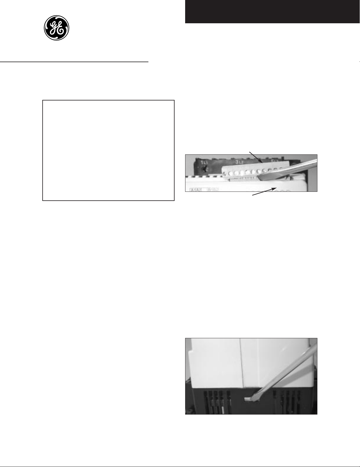
Terminal connector
Cover
Figure 1. Terminal removal
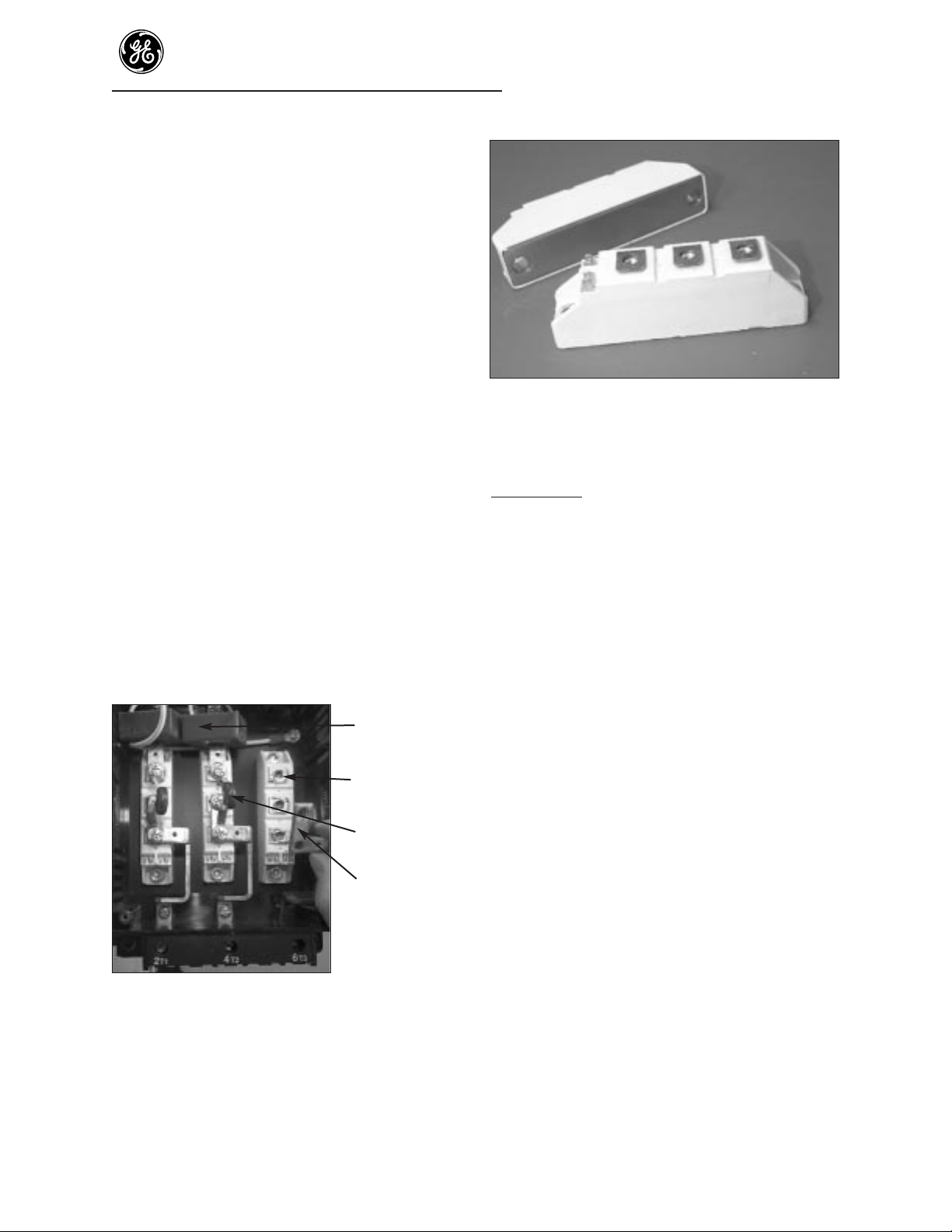
Step 1. Remove the two 12- point plug-in terminal
connectors by inserting a flat-head screwdriver
between the terminal connector and the
ASTAT-CD Plus cover.
Do not remove wiring from terminal
connectors.
Carefully release the terminal connector from
pins (Figure 1). Carefully pull the terminal
connectors (with wiring) straight off the
ASTAT-CD Plus starter.
Step 2. Remove the plastic cover by using a flat-head
screwdriver to depress and release the plastic
tab on each side of the cover (Figure 2).
Figure 2. Cover removal
1
ASTAT®-CD Plus Solid-State Starters
DEH-40418 Service Instructions
Contents
Size F, G, H or I . . . . . . . . . . . . . . . . . . . . . . . . . . . . . . .1
Cover removal . . . . . . . . . . . . . . . . . . . . . . . . . . . 1
To replace Logic Board . . . . . . . . . . . . . . . . . . . . 2
To replace Power Supply Board . . . . . . . . . . . . . 2
To replace Protection Board . . . . . . . . . . . . . . . . 4
To replace SCR modules . . . . . . . . . . . . . . . . . . . 5
Size J, K, L or M . . . . . . . . . . . . . . . . . . . . . . . . . . . . . . . 7
Cover removal . . . . . . . . . . . . . . . . . . . . . . . . . . . . 7
To replace Logic Board . . . . . . . . . . . . . . . . . . . . 7
To replace Power Supply Board . . . . . . . . . . . . . 8
To replace Protection Board . . . . . . . . . . . . . . . . 9
To replace SCR modules . . . . . . . . . . . . . . . . . . 10
Size N, Q, R or S . . . . . . . . . . . . . . . . . . . . . . . . . . . . . 13
Cover removal . . . . . . . . . . . . . . . . . . . . . . . . . . . 13
To replace Logic Board . . . . . . . . . . . . . . . . . . . 13
To replace Power Supply Board . . . . . . . . . . . . 14
To replace Protection Board . . . . . . . . . . . . . . . 15
To replace SCRs . . . . . . . . . . . . . . . . . . . . . . . . . 16
Size T . . . . . . . . . . . . . . . . . . . . . . . . . . . . . . . . . . . . . . 18
Cover removal . . . . . . . . . . . . . . . . . . . . . . . . . . . 18
To replace Logic Board . . . . . . . . . . . . . . . . . . . 18
To replace Power Supply Board . . . . . . . . . . . . 19
To replace Protection Board . . . . . . . . . . . . . . . 20
To replace SCRs . . . . . . . . . . . . . . . . . . . . . . . . . 21
Size U or V . . . . . . . . . . . . . . . . . . . . . . . . . . . . . . . . . . 24
Cover removal . . . . . . . . . . . . . . . . . . . . . . . . . . . 24
To replace Logic Board . . . . . . . . . . . . . . . . . . . 24
To replace Power Supply Board . . . . . . . . . . . . 25
To replace Protection Board . . . . . . . . . . . . . . . 26
To replace SCR modules . . . . . . . . . . . . . . . . . . 27
Troubleshooting Guide . . . . . . . . . . . . . . . . . . . . . . . 30
Renewal Parts List . . . . . . . . . . . . . . . . . . . . . . . . . . . . 32
Instructions For Changing Circuit
Boards and SCRs
On Sizes F, G, H, I, J, K, L, M, N, Q, R, S, T, U, V
Logic Board, QCX000143
Power Supply Board, QCX000144
Protection Board, See Renewal Parts List, p. 32
SCRs - See Renewal Parts List, p. 32
Page 2
ASTAT-CD Plus Service Instructions
2
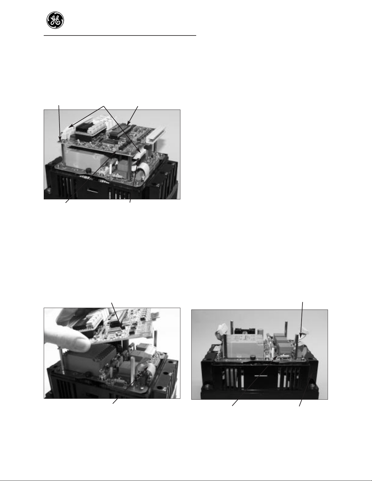
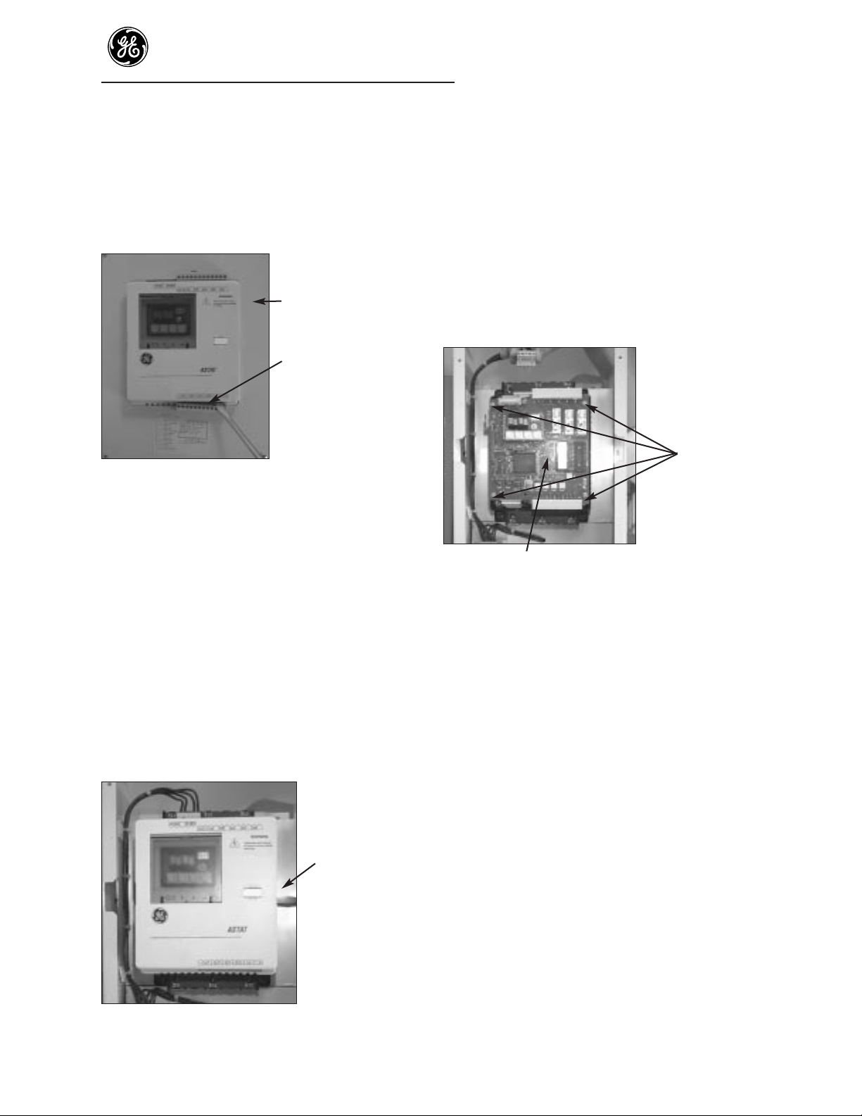
To replace Logic Board (top board)
Important: Always handle boards by
edges and do not distort parts on board.
Unplug Logic
Screws ribbon cable Board
Power Unplug ribbon cable
Supply Board (Step3)
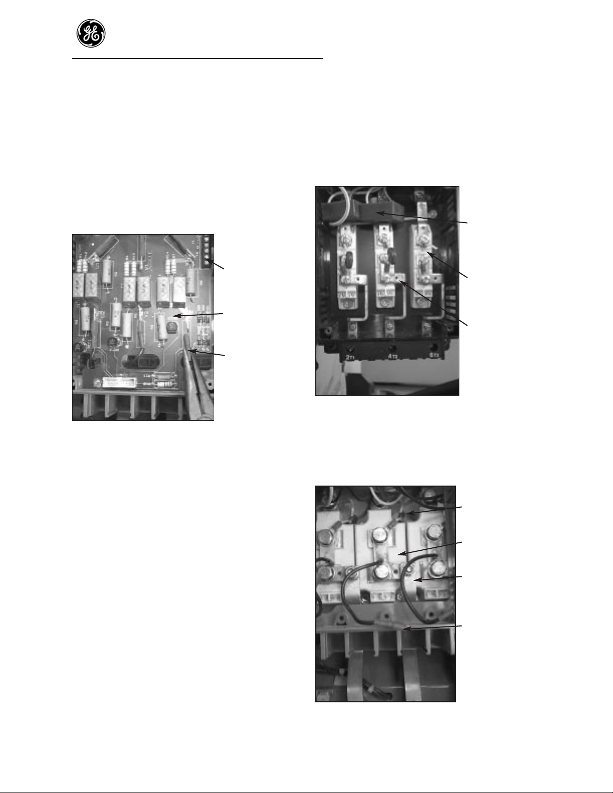
Figure 3. Board and part locations
Step 3. To remove Logic Board, unplug the two
ribbon cables from the Logic Board.
Step 4. Remove the 4 corner screws holding the
Logic Board to the stand-offs below the Logic
Board. Remove the Logic Board.
Logic Board
Ribbon cable
Figure 4. Logic Board removal
Step 5. Reassemble Logic Board to the starter. With
the display on the Logic Board at the upper
left corner, place the board on the standoffs
and attach the Logic Board in the reverse
order as listed in Steps 3 and 4 above. Make
sure the ribbon cable at the bottom of the
ASTAT is fully seated on both circuit boards
and that the ribbon cable will not interfere
with or touch the cover.
Step 6. Reassemble the plastic cover and the terminal
connectors by lowering the cover over the
boards. Carefully push down the cover until
the two tabs snap into place. It may be
necessary to push in slightly on the outside of
the lower plastic housing.
Replace the terminal connectors through the
plastic cover, onto the connector strips. Make
certain that the terminal connectors snap into
place.
To replace Power Supply Board
NOTE: POWER MUST BE REMOVED
BEFORE SERVICING.
The Power Supply Board location is shown
in Figure 5. It has gray and orange
transformers visible from the sides.
Step 7. Remove the cover and Logic Board using
steps 1 - 4.
Ribbon cable
Power Supply Board Control housing
Figure 5. Power Supply Board
Page 3
ASTAT-CD Plus Service Instructions
3
Step 8. Remove the 4 screws holding the Power
Supply Board to the black plastic housing
(Figure 6).
Screws to remove
Figure 6. Removing screws holding Power
Supply Board
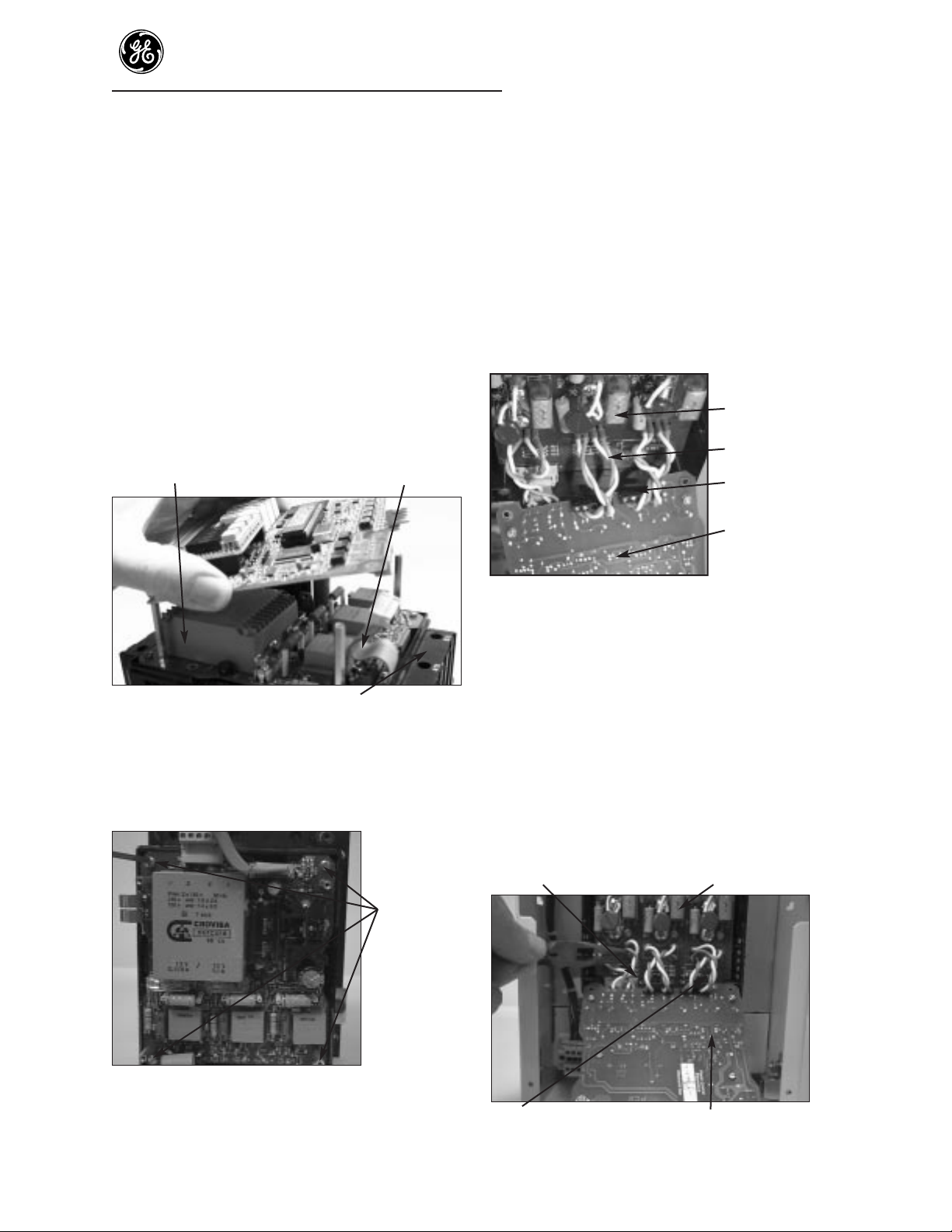
Step 9. Lower the top of the Power Supply Board to
view the yellow and blue gate leads to the
SCRs (Figure 7).
NOTE: Check the blue and yellow gate wires
for a number marking before removing
these wires. Each gate wire must have a
number marking correlating to the terminal
numbers on the Power Supply Board (1
through 12) to facilitate reassembly.
Gate leads Protection Board
Bottom of Power Supply Board Gate terminal board
Figure 7. Gate leads, Protection and
Power Supply Boards
Step 10. Remove the blue and yellow gate wires from
the small 4- point gate Terminal Boards, 1 on
the component side and 2 on the solder side
of the Power Supply Board, with a small
screwdriver.
These wires must be reconnected to the new
Power Supply Board at the proper numbered
terminals for proper operation of the starter.
Remove the Power Supply Board. Remove
the hex standoffs, nuts and washers from the
Power Supply Board for use on the
replacement board.
Step 11. Reassemble the standoffs to the new Power
Supply Board. Reconnect the gate wires.
Reference Figure 8 for gate lead connections.
Step 12. Reassemble the Logic Board, cover and
terminal connectors using Steps 5 - 6.
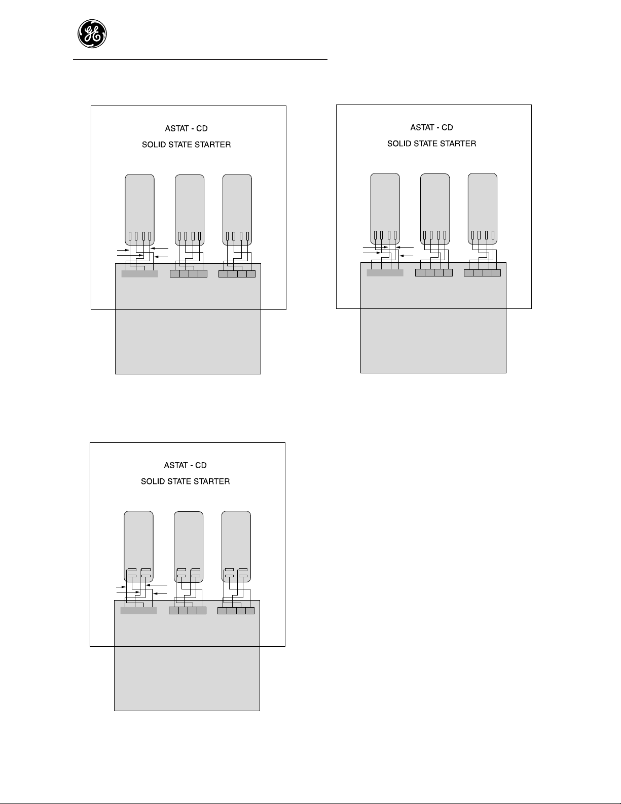
Figure 8. Gate lead connections
Y= yellow wire.
B = blue wire.
SCR lead pairs are to be twisted to reduce EMI
(not shown in sketch).
Page 4
ASTAT-CD Plus Service Instructions
4
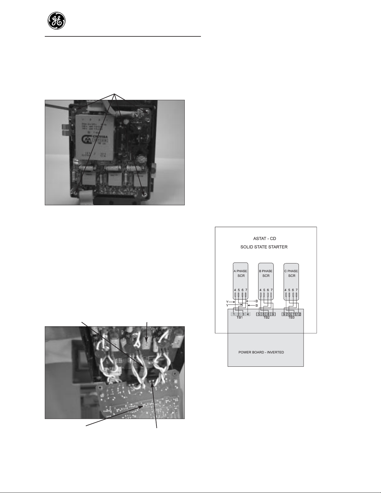
To replace Protection Board
NOTE: POWER MUST BE REMOVED
BEFORE SERVICING.
Current
transformers
6- point Terminal
Board
MOVs
Protection Board
Figure 9. Protection Board
Step 13. Remove the cover, Logic Board and Power
Supply Board using steps 1 - 10.
Step 14. Reposition red MOVs as shown. Raise MOVs
and twist so that Protection Board can be
removed over the MOVs (Figure 10).
MOV
Power
Supply
and Logic
Board
assembly
Figure 10. MOV positioning
Step 15. Disconnect the 4 leads from the 2 current
transformers and remove the jumper on pins
1 and 2 on the 6 -point Terminal Board (TB),
located at the top right edge of the Protection
Board. Identify these lead locations to assure
the same connections are made to the 6point Terminal Board on the new Protection
Board (Figure 11).
Current
transformer leads
6- point Terminal
Board
Small screwdriver
Figure 11. Removing wires from Terminal
Board
Step 16. Loosen the 6 screws holding the Protection
Board to the main bus bars. Remove the
Protection Board from the ASTAT-CD Plus
(Figure 12).
Remove 6 screws holding Protection Board
Figure 12. Remove screws
Page 5
ASTAT-CD Plus Service Instructions
5
Reassembly
Step 17. Reassemble the new Protection Board to the
starter with screws, CT leads and jumper.
Reassemble the Power Supply Board, Logic
Board, cover and terminal connections using
Steps 11, 5 and 6.
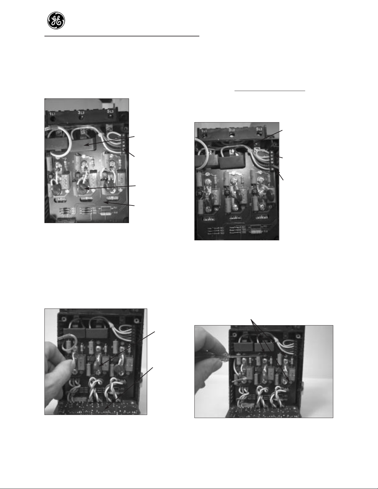
To replace SCR modules
(Sizes F, G,H and I)
NOTE: POWER MUST BE REMOVED
BEFORE SERVICING.
Disassembly
Step 18. Remove the Logic Board, Power Supply
Board and Protection Board using Steps
13-16.
Step 19. Remove MOVs and bus bars from the SCR
Module to be replaced (Figure 13).
Step 20. Remove the mounting screws at each end of
the SCR Module and remove the SCR
Module. Retain all parts and hardware
removed from the SCR module for
reassembly.
Current
transformers
SCR modules
MOV
Bus bars
Figure 13. Removing bus bars
Figure 14. SCR Modules removed
Assembly
Requires tools (#2 Phillips head screwdriver, Allen
wrench and Torque wrench for screws), Scotchbrite
or equivalent abrasive, a mild solvent to clean surfaces
and Electrolube 2 GX or equivalent thermal grease.
The mounting surface of the heatsink must be flat
and clean (i.e., bare metal) and the SCR surface must
be clean. Thermal compound must be coated on all
mating surfaces between the SCR package and the
heatsink. Care must be taken to use the specified
torque for mounting the SCR package.Step 21.
For SCR module mounting, clean the heatsink
surface with a fine abrasive such as Scotchbrite,
remove all particles from the surface of the heatsink
and wipe the SCR mounting surface with a mild
solvent. Apply a light coat of thermal compound such
as Electrolube 2 GX to both the SCR and heatsink
surfaces. Place the contact face of the SCR package on
the mating heatsink surface and move the SCR
package back and forth several times to distribute the
thermal compound evenly over the contact surfaces.
Step 22. Use the screws provided to attach the SCR
package to the heatsink. Tighten the screws
alternately to the specified torque
requirement for the SCR package.
Torque requirements are as follows: Tighten
the screws through the SCR package to
heatsink— 44 in lb.
Page 6
ASTAT-CD Plus Service Instructions
6
Step 23. Reassemble Bus Bars and MOVs to SCR
Modules with torque of 26 in lbs.
Step 24. Reassemble Protection Board, Power Supply
Board, Logic Board, cover and terminal
connectors using Steps 17, 11, 5 and 6.
Remove all power from ASTAT-CD Plus
SCR must be disconnected from ASTAT-CD Plus control (yellow and blue
leads disconnected from SCR) and no load connected to ASTAT-CD Plus.
S2
+
5VDC
-
SCR Test Circuit
Anode
20Ω
Gate
1W
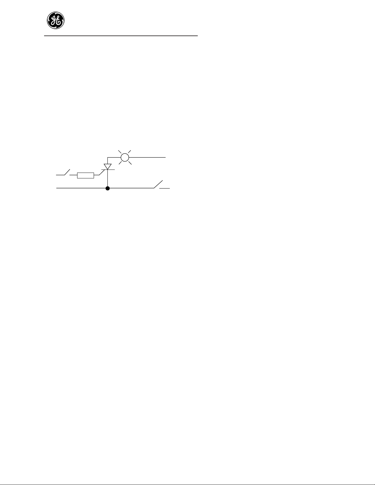
Light
(~.15AMP to .20AMP LOAD)
(SCR)
Cathode
S1
+
-
Figure STC
With S1 closed and S2 open, the lamp should be off.
If lamp is on, SCR is shorted.
With S1 closed and S2 closed, the lamp should turn on.
When S2 is opened, lamp should stay on. SCR is good.
Page 7
ASTAT-CD Plus Service Instructions
7
Sizes J, K, L or M
Cover Removal
NOTE: POWER MUST BE REMOVED
BEFORE SERVICING.
Steel cover
Terminal connector
Figure 1. Remove terminal connectors
Step 1. Remove the two 12- point plug-in terminal
connectors by inserting a flat-head
screwdriver between the terminal connector
and the ASTAT-CD Plus cover.
Do not remove wiring from terminal
connectors.
Carefully release the terminal connectors
from pins (Figure 1). Carefully pull the
terminal connectors (with wiring) straight off
the ASTAT-CD Plus starter.
Step 2. Remove the front steel cover by removing the
4 Phillips screws. Set steel cover aside.
Screwdriver
through slot in
side of steel
housing
Figure 2. Cover removal
Step 3. Remove the plastic cover by using a flat-head
screwdriver to depress and release the plastic
tab on each side of the cover (Figure 2).
To replace the Logic Board (top board)
Important: Always handle boards by
edges and do not distort parts on board.
Step 4. To remove Logic Board, unplug the two
ribbon cables from the Logic Board.
Screws
Logic Board
Figure 3. Board location
Step 5. Remove the 4 corner screws holding the
Logic Board to the standoffs below the Logic
Board. Remove the Logic Board.
Step 6. Reassemble Logic Board to the starter. With
the display on the Logic Board at the upper
left corner, place the board on the standoffs
and attach the Logic Board in the reverse
order as listed in Steps 5 and 4 above. Make
sure the ribbon cable at the bottom of the
ASTAT is fully seated on both circuit boards
and that the ribbon cable will not interfere
with or touch the cover.
Step 7. Reassemble the plastic cover and the terminal
connectors by lowering the cover over the
boards. Carefully push down the cover until
the two tabs snap into place. It may be
necessary to push in slightly on the outside of
the lower plastic housing.
Replace the front steel cover using the 4
Phillips screws.
Page 8
ASTAT-CD Plus Service Instructions
8
Step 10. If a yellow/green ground wire is connected to
the bottom of the Power Supply Board, it
must be disconnected. Lower the top of the
Power Supply Board to view the yellow and
blue gate leads to the SCRs (Figure 6).
NOTE: Check the blue and yellow gate wires
for a number marking before removing these
wires. Each gate wire must have a number
marking correlating to the terminal numbers
on the Power Supply Board (1 through 12)
to facilitate reassembly.
Protection
Board
Gate leads
Gate Terminal
Board
Bottom of Power
Supply Board
Figure 6. Gate leads, Protection and Power
Supply Boards
Step 11. Remove the blue and yellow gate wires from
the small 4- point gate terminal boards, 1 on
the component side and 2 on the solder side
of the Power Supply Board, with a small
screwdriver. These wires must be reconnected
to the new Power Supply Board at the proper
numbered terminals for proper operation of
the starter. Remove the Power Supply Board.
Remove the hex standoffs, nuts and washers
from the Power Supply Board for use on the
replacement board.
Remove gate leads Protection Board
Gate leads Power Supply & Logic Board assembly
Figure 7. Board location
Replace the terminal connectors through the
plastic cover, onto the connector strips. Make
certain that the terminal connectors snap into
place.
To replace Power Supply Board
NOTE: POWER MUST BE REMOVED
BEFORE SERVICING.
The Power Supply Board location is shown
below (Figure 4). It has gray and orange
transformers visible from the sides.
Step 8 Remove the cover and Logic Board using
Steps 1 - 5.
Power Supply Board Ribbon cable
Control housing
Figure 4. Removing Logic Board
Step 9. Remove the 4 screws holding the Power
Supply Board to the black plastic housing
(Figure 5).
Screws to
remove
Figure 5. Removing screws holding
Power Supply Board
Page 9
ASTAT-CD Plus Service Instructions
9
Step 12. Reassemble the standoffs to the new Power
Supply Board. Reconnect the gate wires.
Reference Figure 8 for gate lead connections
for Size J, Figure 9 for Size K, or Figure 10 for
Sizes L and M.
Step 13. Reassemble the Logic Board, cover and
terminal connectors using Steps 6 - 7.
Figure 8. Gate lead connections (Size J)
Figure 10. Gate lead connections
(Sizes L and M)
SCR lead pairs are to be twisted to
reduce EMI (not shown in sketch).
Figure 9. Gate lead connections (Size K)
Y= yellow wire (gate). B = blue wire (cathode)
A PHASE
SCR
4567 4567 4567
Y
YB
234
1
TB1
B = Blue(SCR-Cathode connection)
Y = Yellow(SCR-Gate connection)
POWER BOARD - INVERTED
B PHASE
SCR
B
5678 91011 12
TB2 TB3
C PHASE
SCR
A PHASE
SCR
4
5
Y
YB
234
1
TB1
B PHASE
SCR
674
5
B
5678 91011 12
674
TB2 TB3
C PHASE
SCR
5
6
7
A PHASE
SCR
4567 4567 4567
Y
Y
234
1
TB1
B = Blue(SCR-Cathode connection)
Y = Yellow(SCR-Gate connection)
POWER SUPPLY BOARD - SOLDERSIDE
B PHASE
SCR
B
B
5678 91011 12
TB2 TB3
C PHASE
SCR
B = Blue(SCR-Cathode connection)
Y = Yellow(SCR-Gate connection)
POWER SUPPLY BOARD - SOLDERSIDE
Page 10
ASTAT-CD Plus Service Instructions
10
To replace the Protection Board.
NOTE: POWER MUST BE REMOVED
BEFORE SERVICING.
Step 14. Remove the cover and Logic Board/ Power
Supply Board assembly using steps 1 - 3, 9-10.
Step 15. Remove 6 wire connectors from the
Protection Board (Figure 11). Note the
locations of these terminals for reassembly.
6- point Terminal
Board
Protection
Board
Wire connectors
Figure 11. Remove push on wire connectors
Step 16. Disconnect the 4 leads from the two current
transformers and the 2 leads from the
thermostat to the 6 -point Terminal Board
(TB) (located at the top right edge of the
Protection Board)(Figure 10). Label these
leads to assure connections are the same to
the 6- point terminal board on the new
Protection Board.
Step 17. Loosen the 4 screws holding the Protection
Board to the housing. Remove the Protection
Board from the ASTAT-CD Plus.
Step 18. Reassemble the new Protection Board, CT
leads, thermostat leads, screws, gate wires and
ground wire, Logic and Power Supply Board
assembly, screws and ribbon connectors in the
reverse order of the above listed disassembly
(steps 12 and 6).
Step 19. Reassemble the plastic cover, connectors and
sheet metal covers using step 7.
To replace SCR modules
NOTE: POWER MUST BE REMOVED
BEFORE SERVICING.
SCR disassembly instructions - Size J
Current
transformers
SCR modules
Bus bars
Figure 12. SCR module, MOV and bus bar
location (Size J)
SCR disassembly instructions Sizes L and M
MOV
SCR modules
Bus bars
Connectors to
Protection Board
Figure 13. SCR module, MOV and bus bar
location (Sizes L and M)
Page 11

Mounting screws
for black housing
Figure 16. Black housing removal
Step 22. Remove 4 screws from black housing and
remove housing (Figure 15).
Figure 17. SCR modules, Size J
Figure 18. SCR module, Sizes L and M
ASTAT-CD Plus Service Instructions
11
Step 20. Remove the cover and circuit boards using
steps 14 - 17.
Step 21. With SCR assemblies exposed, remove MOVs
and bus bars from the SCR module to be
replaced. Remove the mounting screws at
each end of the SCR module, lift out the SCR
module. It may be necessary to remove the
black housing in order to remove the SCR
module (see Step 22). Retain all parts and
hardware removed from the SCR module for
reassembly.
Current
transformer
SCR module
MOV
Bus bar
Mounting screw
Figure 14. Parts location (Size J)
MOV
SCR module
Bus bar
Mounting screw
Figure 15. Parts location (Sizes L and M)
Page 12

ASTAT-CD Plus Service Instructions
12
SCR assembly instructions
The mounting surface of the heatsink must be flat
and clean (i.e., bare metal) and the SCR module
surface must be clean. Thermal compound must be
coated on all mating surfaces between the SCR
module and the heatsink. Care must be taken to use
the specified torque for mounting the SCR module.
For SCR module (back to back SCRs in a single
package) on ASTAT-CD Plus sizes J, K, L and M.
Step 23. Clean the heatsink surface with a fine abrasive
such as Scotchbrite, remove all particles from
the surface of the heatsink and wipe the SCR
module mounting surface with a mild solvent.
Step 24. Apply a light coat of thermal compound such
as Electrolube 2 GX to both the SCR module
and heatsink surfaces.
Step 25. Place the contact face of the SCR module and
on the mating heatsink surface and move the
SCR module back and forth several times to
distribute the thermal compound evenly over
the contact surfaces.
Step 26. Use the screws provided to attach the SCR
module to the heatsink. Tighten the screws
alternately to the specified torque
requirement for the SCR module.
Torque requirements are as follows for sizes J,
K, L and M: Tighten the screws through the
SCR module to heatsink to 44 in lb.
Step 27. Reassemble bus bars and MOVs to SCR
modules (Figures 13 and 14). Torque to 26 in
lbs for Size J, 44 in lbs for Size K, and 80 in lbs
for Sizes L and M.
Step 28. Reassemble Protection Board, Power Supply
Board, shield or Communications Board (if
removed), Logic Board, cover and terminal
connectors using Steps 18 and 19.
Remove all power from ASTAT-CD Plus
SCR must be disconnected from ASTAT-CD Plus control (yellow and blue
leads disconnected from SCR) and no load connected to ASTAT-CD Plus.
S2
+
5VDC
-
With S1 closed and S2 open, the lamp should be off.
If lamp is on, SCR is shorted.
With S1 closed and S2 closed, the lamp should turn on.
When S2 is opened, lamp should stay on. SCR is good.
SCR Test Circuit
Anode
20Ω
Gate
1W
Figure STC
Light
(~.15AMP to .20AMP LOAD)
(SCR)
Cathode
S1
+
-
Page 13

ASTAT-CD Plus Service Instructions
13
Carefully release the terminal connectors
from pins (Figure 2) and remove the
connectors (with wiring) from the starter.
Carefully pull the terminal connectors
straight off the ASTAT-CD Plus starter.
Step 3. Remove the plastic cover by using a flat-head
screwdriver to depress and release the plastic
tab on each side of the plastic cover (see
Figure 2 in Sizes F, G, H and I section).
To replace the Logic Board
Important: Always handle boards by
edges and do not distort parts on board.
Step 4. The top printed circuit board is the Logic
Board.
Ribbon cable
Screw
Logic Board
Ribbon cable
Figure 3. Logic Board parts location
Step 5. To remove Logic Board, unplug the two
ribbon cables from the Logic Board.
Step 6. Remove the 4 corner screws holding the
Logic Board to the standoffs below the Logic
Board. Remove the Logic Board (Figure 3).
Step 7. Reassemble Logic Board to the starter. With
the display on the Logic Board at the upper
left corner, place the board on the standoffs
and attach the Logic Board in the reverse
order as listed in Steps 6 and 5 above. Make
sure the ribbon cable at the bottom of the
ASTAT is fully seated on both circuit boards
and that the ribbon cable will not interfere
with or touch the cover.
Sizes N, Q, R or S
Cover removal
NOTE: POWER MUST BE REMOVED
BEFORE SERVICING.
Screws
Figure 1. Cover screw locations
Step 1. Remove the front steel cover by removing the
4 Phillips screws (Figure 1).
Terminal connector Cover
Figure 2. Terminal removal
Step 2. Remove the two 12- point plug-in terminal
connectors by inserting a flat- head
screwdriver between the terminal connectors
and that ASTAT-CD Plus cover (Figure 2).
Do not remove wiring from
terminal connectors.
Page 14

ASTAT-CD Plus Service Instructions
14
Step 8. Reassemble the plastic cover and the terminal
connectors by lowering the cover over the
boards. Carefully push down the cover until
the two tabs snap into place. It may be
necessary to push in slightly on the outside of
the lower plastic housing.
Step 9. Replace the terminal connectors through the
plastic cover, onto the connector strips. Make
certain that the terminal connectors snap into
place (Figure 2).
Step 10. Replace the front steel cover using the 4
Phillips screws (Figure 1).
To replace Power Supply Board
NOTE: POWER MUST BE REMOVED
BEFORE SERVICING.
Step 11. Remove the cover and Logic Board using
steps 1 - 6.
The Power Supply Board location is shown in
Figure 4. It has gray and orange transformers
visible from the sides.
Ground wire Hex standoff Ribbon cable
Power Supply Board Control housing
Figure 4. Removing Logic Board
Screws
to remove
Figure 5. Removing screws holding Power
Supply Board.
Step 12. Remove the 4 screws holding the Power
Supply Board to the black plastic housing.
Step 13. If a yellow/green ground wire is connected to
the bottom of the Power Supply Board, it
must be disconnected. Lower the top of the
Power Supply Board to view the yellow and
blue gate leads to the SCRs (Figure 6).
NOTE: Check the blue and yellow gate wires
for a number marking before removing these
wires. Each gate wire must have a number
marking correlating to the terminal numbers
on the Power Supply Board (1 through 12) to
facilitate reassembly.
Step 14. Remove the blue and yellow gate wires from
the small 4- point gate Terminal Boards, 1 on
the component side and 2 on the solder side
of the Power Supply Board, with a small
screwdriver (Figure 6).
Protection Board
Gate leads
Gate Terminal
Board
Bottom of Power
Supply Board
Figure 6. Gate leads, Protection and Power
Supply Boards
Page 15

To replace the Protection Board.
NOTE: POWER MUST BE REMOVED
BEFORE SERVICING.
Step 17. Remove the Cover, steps 1-3, and remove the
Logic and Power Supply Board assembly by
removing 4 screws holding the Power Supply
Board to the black housing. If a
yellow/green ground wire is connected to
the bottom of the Power Supply Board, it
must be disconnected. Lower the Logic and
Power Supply Board assembly (Figure 8).
Remove the blue and yellow gate leads per
steps 13 and 14.
6-point Terminal Board
Protection Board
6-wire connectors
Power Supply and
Logic Board assembly
Figure 8. Board location
6- point Terminal
Board
Protection Board
Wire connectors
Mounting screw
Figure 9. Remove wire connectors
Step 18. Remove 6- wire connectors from the
Protection Board (Figure 9). Note the
locations of these terminals for reassembly.
ASTAT-CD Plus Service Instructions
15
These wires must be reconnected to the new
Power Supply Board at the proper numbered
terminals for proper operation of the starter.
Remove the Power Supply Board. Remove
the hex standoffs, nuts and washers from the
Power Supply Board for use on the
replacement boards.
Step 15. Reassemble the standoffs to the new Power
Supply Board. Reconnect the gate wires,
(ground wire if removed), screws and Shield
Board and standoffs (if removed). Reference
Figure 7 for gate lead connections.
Step 16. Reassemble the Logic Board, cover and
terminal connectors using Steps 7-10.
Figure 7. Gate lead connections
Y= yellow wire. B = blue wire.
SCR lead pairs are to be twisted to
reduce EMI (not shown in sketch).
Page 16

ASTAT-CD Plus Service Instructions
16
Step 19. Disconnect the 4 leads from the two current
transformers and the 2 leads from the
thermostat to the 6- point Terminal Board
(Figure 8). Label these leads to assure
connections are the same to the 6- point
Terminal Board on the new Protection
Board.
Step 20. Loosen the 4 mounting screws holding the
Protection Board to the housing. Remove the
Protection Board from the ASTAT-CD Plus.
Reassembly
Step 21. Reassemble the new Protection Board, CT
leads, thermostat leads, screws, gate wires and
ground wire, Logic and Power Supply Board
assembly, screws and ribbon connectors in the
reverse order of the above listed disassembly
(Steps 17-20).
Step 22. Reassemble the plastic cover, connectors and
sheet metal covers using steps 8 - 10.
To replace SCRs
Insulating Terminal Circuit board
cover board assembly
Transformer Heat sink Bus bar support Bus
(Sizes R & S only) cover bracket and bar
fan assembly
Figure 10. Parts locations insulating cover
Bolts holding heatsink
assembly to housing Steel housing
SCR and heatsink assembly Gate and cathode leads
Figure 11. SCR and heatsink location
Step 23. Remove cover and circuit boards using
Steps 17-20.
Step 24. Remove bus bars, insulators, barriers, fan
assemblies, thermostat wires and other parts
that interfere with removal of the
SCR/heatsink assembly (Figure 10).
Step 25. Remove the SCR/heatsink assembly from the
ASTAT-CD Plus housing (Figure 11). Retain
all parts and hardware for reassembly.
Step 26. Remove MOVs, thermostat, mounting
insulator and other parts to allow disassembly
of the clamps and SCRs from the heatsinks
(Figure 12).
CAUTION: Do not adjust or move the preset nut
(6) (Figure 13). The preset nut (6) and the
belleville washers under the cross piece (5) are
preset to the required force for assembly and
clamping of the new SCR to the heatsink.
SCR and heatsink
assembly
Clamp assembly
MOV
Thermostat
Mounting plate
Figure 12. SCR and heatsink assembly
Page 17

ASTAT-CD Plus Service Instructions
17
Figure 13. SCR and heatsink assembly
Step 27. Loosen the tension bolts (10) alternately 1/4
turn at a time on each SCR until pressure
releases on the SCRs. Remove bolts and
clamps to release the heatsinks. Retain the
gate and cathode leads from the SCRs for use
when reassembling the SCRs and heatsinks.
CAUTION: Do not adjust or move the pre-set nut
(6) (Figure 13). The pre-set nut (6) and the
belleville washers under the cross piece (5) are
pre-set to the required force for assembly and
clamping of the new SCR to the heatsink.
Note: The mounting surface of the heatsink
must be flat and clean (i.e., bare metal) and
the SCR surface must be clean. Thermal
compound must be coated on all mating
surfaces between the SCR and the heatsink.
Step 28. Clean both heat sink surfaces with a fine
abrasive such as Scotchbrite, then remove all
particles from the surface of the heatsink. To
clean the SCR, wipe the SCR mounting
surfaces with a mild solvent.
Step 29. Apply a light coat of thermal compound such
as Electrolube 2 GX to both sides of the SCR
and to both heatsink surfaces that mate
to the SCR.
Step 30. Make sure that the orientation of the SCR is
correct (as disassembled) and place the
contact face of the SCR over the locating pin
in the mating heatsink surface. Twist the SCR
backward and forward by hand applying firm
pressure to the SCR. Remove the SCR from
10 Tension bolt
4 Pressure plates
5 Cross piece
6 Pre-set nut
8 Metal gauge
7 Belleville washers
3 Cross piece
9 Center pin
1 Heatsinks
2 SCR
11 Insulated sleeve
the heatsink, the mating surfaces must be
uniformly coated with thermal compound. If
the mating surfaces are not coated evenly,
apply slightly more thermal compound to the
surfaces and twist back and forth as before.
Step 31. With the (2) SCRs located properly on the
heatsink, i.e. the gate and cathode terminals
on the SCRs must be on the proper side of
the heatsink assembly (as disassembled),
place the other heatsink over the SCRs.
Refer to Figure 13.
The clamp is assembled so that the cross
piece (5) with the pressure plate (4) and the
tension bolts (10) are at the top. Underneath,
the cross piece (3) with the pressure plate (4)
is put in position and the two tension bolts
(10) are alternately tightened carefully until a
slight resistance is felt. Check that both cross
pieces (3) and (5) are parallel. For this check,
it is sufficient to check that the tension bolts
project equal distances beyond the cross
piece (3). The tension bolts (10) may now be
alternately tightened 1/4 turn at a time until
the metal gauge (8) can be easily moved.
Note - The tension bolts should not be
tightened beyond the point that the metal
gauge (8) can be easily moved. Never adjust
or change the position of the preset nut (6).
The preset nut (6) determines the clamping
force applied to the SCR.
Light
+
+
-
-
S2
S1
20Ω
1W
(SCR)
Cathode
Anode
Gate
(~.15AMP to .20AMP LOAD)
5VDC
Figure STC
SCR Test Circuit
Remove all power from ASTAT-CD Plus
Test SCR's only when clamped in heatsink assembly.
With S1 closed and S2 open, the lamp should be off.
If lamp is on, SCR is shorted.
With S1 closed and S2 closed, the lamp should turn on.
When S2 is opened, lamp should stay on. SCR is good.
SCR must be disconnected from ASTAT-CD Plus control (yellow and blue
leads disconnected from SCR) and no load connected to ASTAT-CD Plus.
Page 18

ASTAT-CD Plus Service Instructions
18
NOTE: POWER MUST BE REMOVED
BEFORE SERVICING.
Size T
Cover removal
Step 1. Remove the front steel cover by removing the
4 Phillips screws (Figure 1).
Screws
Figure 1. Cover screw locations
Step 2. Remove the two 12-point plug-in terminal
connectors by inserting a flat-head
screwdriver between the terminal connectors
and the ASTAT-CD Plus cover (Figure 2).
Carefully release the terminal connectors
from pins (Figure 2) and remove the
connectors (with wiring) from the starter.
Carefully pull the terminal connectors
straight off the ASTAT-CD Plus starter.
Do not remove the wiring from
terminal connectors.
Cover
Terminal connector
Figure 2. Terminal removal
Step 3. Remove the plastic cover by using a flathead
screwdriver to depress and release the plastic
tab on each side of the plastic cover (see
Figure on page 1).
To replace the Logic Board
Important: Always handle boards by
edges and do not distort parts on board
Step 4. The top printed circuit board is the Logic
Board.
Ribbon cable
Screw
Logic Board
Ribbon cable
Screw
Figure 3. Logic Board parts location
Step 5. To remove Logic Board, unplug the two
ribbon cables from the Logic Board.
Step 6. Remove the 4 corner screws holding the
Logic Board to the standoffs below the Logic
Board. Remove the Logic Board.
Step 7. Reassemble new Logic Board to the starter.
With the display on the Logic Board at the
upper left corner, place the board on the
standoffs and attach the Logic Board in the
reverse order as listed in steps 6 and 5 above.
Make sure the ribbon cable at the bottom of
the ASTAT is fully seated on both circuit
boards and that the ribbon cable will not
interfere with or touch the cover.
Page 19

ASTAT-CD Plus Service Instructions
19
Step 8. Reassemble the plastic cover and the terminal
connectors by lowering the cover over the
boards. Carefully push down the cover until
the two tabs snap into place. It may be
necessary to push in slightly on the outside of
the lower plastic housing.
Step 9. Replace the terminal connectors through the
plastic cover, onto the connector strips. Make
certain that the terminal connectors snap into
place (Figure 2).
Step 10. Replace the front steel cover using the 4
Phillips screws (Figure 1).
To replace Power Supply Board
NOTE: POWER MUST BE REMOVED
BEFORE SERVICING.
Step 11. Remove the cover and Logic Board using
steps 1-6. The Power Supply Board location is
shown in Figure 4. It has gray and orange
transformers visible from the sides.
Figure 4. Removing Logic Board
Screw
Figure 5. Removing screws holding Power
Supply Board
Step 12. Remove the 4 screws holding the Power
Supply Board to the black plastic housing.
Step 13. If a yellow/green ground wire is connected to
the bottom of the Power Supply Board, it
must be disconnected. Lower the top of the
Power Supply Board to view the yellow and
blue gate leads to the SCRs (Figure 6).
NOTE: Check the blue and yellow gate wires
for a number marking before removing these
wires. Each gate wire must have a number
marking correlating to the terminal numbers
on the Power Supply Board (1 through 12) to
facilitate reassembly.
Step 14. Remove the blue and yellow gate wires from
the small 4-point gate Terminal Boards, 1 on
the component side and 2 on the solder side
of the Power Supply Board, with a small
screwdriver (Figure 6). These wires must be
reconnected to the new Power Supply Board
at the proper numbered terminals for proper
operation of the starter.
Page 20

ASTAT-CD Plus Service Instructions
20
Protection Board Gate leads
Bottom of Power Supply Board Gate terminal board
Figure 6. Gate leads, Protection and Power
Supply Boards
Remove the Power Supply Board. Remove
the hex standoffs, nuts and washers from the
Power Supply Board for use on the
replacement board.
Step 15. Reassemble the standoffs to the new Power
Supply Board. Reconnect the gate wires to
the Power Supply Board (terminals 1 to 12)
and reinstall the 4 screws which hold the
Power Supply Board to the black plastic
housing. Refer to (Figure 7) for gate lead
connections.
Step 16. Reassemble the Logic Board, cover and
terminal connectors using steps 7-10.
Figure 7. Gate lead connections
Y= Yellow wire B = Blue wire
SCR pairs are to be twisted to reduce EMI (not shown in sketch).
To replace the Protection Board.
NOTE: POWER MUST BE REMOVED
BEFORE SERVICING.
Step 17. Remove the Cover, steps 1-3, and remove the
(Logic and Power Supply Board assembly) by
removing the 4 screws holding the Power
Supply Board to the black housing. If a
yellow/green wire is connected to the bottom
of the Power Supply Board, it must be
disconnected. Lower the Logic and Power
Supply Board assembly (Figure 8). Remove
the blue and yellow gate wires per steps 13
and 14.
6-point Terminal
Board
Protection Board
6 wire connectors
Power Supply and
Logic Board
assembly
Figure 8. Board location
Mounting Screw 6-point Terminal Board
Protector Board Wire Connectors
Figure 9. Remove wire connectors
Page 21

ASTAT-CD Plus Service Instructions
21
Step 18. Label the 6 push-on wire connectors with the
numbers printed on the P.C. Board (U1, V1,
W1, U2, V2, W2). Remove 6 push-on wire
connectors from the Protection Board
(Figure 9). Note the location of these
terminals for reassembly.
Step 19. Label the 4 leads from the two current
transformers and the 2 leads from the
thermostats to assure connections are the
same to the 6-point Terminal Board on the
new Protection Board. Disconnect the 4 leads
from the two current transformers and the 2
leads from the thermostats to the 6-point
Terminal Board (Figure 8).
Step 20. Loosen the mounting screws holding the
Protection Board to the housing. Remove the
Protection Board from the ASTAT-CD Plus.
Reassembly
Step 21. Reassemble the new Protection Board, the
push-on wire connectors, the CT leads,
thermostat leads, screws, gate wires and
ground wire (if used), Logic and Power
Supply Board assembly, screws and ribbon
connectors in the reverse order of the above
listed disassembly (Steps 16-20).
Step 22. Reassemble the plastic cover, connectors and
sheet metal cover using steps 8-10.
To replace SCRs
NOTE: POWER MUST BE REMOVED
BEFORE SERVICING.
Step 23. Remove the front cover by removing the (4)
Phillips head screws (Figure 1).
Step 24. Phase 1 or 3 - Remove bus bars, the fan
assembly, the top ventilating cover and the
heat sink insulator cover. Remove the
thermostat wires, gate and cathode leads from
the SCRs, current transformer leads from the
C. T. (only on Phase 1) and other parts that
interfere with removal of the SCR/heatsink
assembly (Figure 10).
Phase 2
- Remove bus bars, the fan assembly,
the top ventilating cover and the heat sink
insulator covers from both phase 1 and Phase
3 heatsink assemblies. Remove (4) Allen
screws in the black plastic bottom housing
that holds the Control assembly to the
heatsink assembly and move the assembly to
the side. Remove the thermostat wires, gate
and cathode leads from the SCRs, current
transformer leads from the C. T.’s, and other
parts that interfere with removal of the
SCR/heatsink assembly (Figure 10).
Terminal Blower Circuit board Heatsink
Board transformers assembly insulating cover
Phase 1 Phase 2 Phase 3
Current MOV Bus bar support Bus bar
transformers bracket and
fan assembly
Figure 10. Parts locations insulating covers
Step 25. Remove the bolts on the ends of the heatsink
assembly that hold the H. S. assembly to the
housing insulators. Then slide the H. S.
assembly out the bottom of that ASTAT
housing. (Figure 11). Retain all parts and
hardware for reassembly.
Page 22

ASTAT-CD Plus Service Instructions
22
MOV Heatsink SCR gate and
leads assembly cathode leads
Thermostat Bolts holding heatsink
assembly to housing
Figure 11. SCR and heatsink location
Step 26. SCR/Heat sink disassembly - Remove the
thermostat, mounting insulator and other
parts to allow disassembly of the clamps and
SCRs from the heatsinks (Figure 12).
SCR and heatsink
assembly
Clamp assembly
Mounting Plate
Thermostat
Figure 12. SCR and heatsink assembly
CAUTION: Do not adjust or move the preset nut
(6) (Figure 13). The preset nut (6) and the bevel
washers under the cross piece (5) are preset to the
required force for assembly and clamping of the
new SCR to the heatsink.
Step 27. Removing the SCRs
(Figure 13) - Loosen the
tension bolts (10) alternately, 1/4 turn at a
time, on each SCR until pressure releases on
the SCRs. Remove bolts and clamps to release
the heatsinks. Note: record the position of
both SCRs (gate and cathode connectors on
the SCR) for reassembly.
Caution: Do not adjust or move the pre-set nut (6)
(Figure 13). The pre-set nut and the bevel washers
under the cross piece (5) are pre-set to the required
force for assembly and clamping of the new SCR to
the heatsink.
Note: The mounting surface of the heatsink
must be flat and clean (i.e., bare metal) and
the SCR surface must be clean. Thermal
compound must be coated on all mating
surfaces between the SCR and the heatsink.
Figure 13. SCR and heatsink assembly
Step 28. Clean both heat sink surfaces with a fine
abrasive such as Scotch brite, then remove all
particles from the surface of the heatsinks. To
clean the SCR, wipe the SCR with a mild
solvent.
Step 29. Apply a light coat of thermal compound such
as Electrolube 2GX to both sides of the SCR
and to both heatsink surfaces that mate to the
SCR.
Step 30.Make sure that the orientation of the SCR is
correct(as disassembled) and place the
contact face of the SCR over the locating pin
in the mating heatsink surface. Twist the SCR
10 Tension bolt
4 Pressure plates
5 Cross piece
6 Pre-set nut
8 Metal gauge
7 Belleville washers
3 Cross piece
9 Center pin
1 Heatsinks
2 SCR
11 Insulated sleeve
Page 23

ASTAT-CD Plus Service Instructions
23
backward and forward by hand applying firm
pressure to the SCR. Remove the SCR from
the heatsink, the mating surfaces must be
uniformly coated with thermal compound. If
the mating surfaces are not coated evenly,
apply slightly more thermal compound to the
surfaces and twist back and forth as before.
Step 31. With the 2 SCRs located properly on the
heatsink, i.e. the gate and cathode terminals
on the SCR must be on the proper side of the
heatsink assembly (as disassembled), place
the other heatsink over the SCRs. Refer to
Figure 13.
The clamp is assembled so that the cross
piece(5) with the pressure plate(4) and the
tension bolts (10) are at the top. Underneath
the cross piece (3) with the pressure plate (4)
is put in position and the two tension bolts
(10) are alternately tightened carefully until a
slight resistance is felt. Check that both cross
pieces (3) and (5) are parallel. For this check,
it is sufficient to check that the tension bolts
project equal distances beyond the cross
piece(3). The tension bolts (10) may now be
alternately tightened 1/4 turn at time until
the metal gauge (8) can be easily moved.
NOTE: The tension bolts should not be
tightened beyond the point that the metal
gauge (8) can be easily moved. Never adjust
the preset nut (6).
Light
+
+
-
-
S2
S1
20Ω
1W
(SCR)
Cathode
Anode
Gate
(~.15AMP to .20AMP LOAD)
5VDC
Figure STC
SCR Test Circuit
Remove all power from ASTAT-CD Plus
With S1 closed and S2 open, the lamp should be off.
If lamp is on, SCR is shorted.
With S1 closed and S2 closed, the lamp should turn on.
When S2 is opened, lamp should stay on. SCR is good.
SCR must be disconnected from ASTAT-CD Plus control (yellow and blue
leads disconnected from SCR) and no load connected to ASTAT-CD Plus.
Page 24

ASTAT-CD Plus Service Instructions
24
Sizes U and V
Cover removal
NOTE: POWER MUST BE REMOVED
BEFORE SERVICING.
Step 1. Remove the front steel cover by removing the
6 Phillips screws (Figure 1).
Screws
Figure 1. Cover screw locations
Step 2. Remove the two 12-point plug-in terminal
connectors by inserting a flat-head
screwdriver between the terminal connectors
and the ASTAT-CD Plus cover (Figure 2).
Carefully release the terminal connectors
from pins (Figure 2) and remove the
connectors (with wiring) from the starter.
Carefully pull the terminal connectors
straight off the ASTAT-CD Plus starter.
Do not remove the wiring from
terminal connectors.
Cover
Terminal connector
Figure 2. Terminal removal
Step 3. Remove the plastic cover by using a flathead
screwdriver to depress and release the plastic
tab on each side of the plastic cover (see
Figure 2 in F, G, H and I section).
To replace the Logic Board
Important: Always handle boards by
edges and do not distort parts on board
Step 4. The top printed circuit board is the Logic
Board.
Step 5. To remove Logic Board, unplug the two
ribbon cables from the Logic Board.
Ribbon cable
Logic Board
Ribbon cable
Screw
Figure 3. Logic Board parts locations
Step 6. Remove the 4 corner screws holding the
Logic Board to the standoffs below the Logic
Board. Remove the Logic Board.
Step 7. Reassemble new Logic Board to the starter.
With the display on the Logic Board at the
upper left corner, place the board on the
standoffs and attach the Logic Board in the
reverse order as listed in steps 6 and 5 above.
Make sure the ribbon cable at the bottom of
the ASTAT is fully seated on both circuit
boards and that the ribbon cable will not
interfere with or touch the cover.
Step 8. Reassemble the plastic cover and the terminal
connectors by lowering the cover over the
boards. Carefully push down the cover until
the two tabs snap into place. It may be
necessary to push in slightly on the outside of
the lower plastic housing.
Page 25

ASTAT-CD Plus Service Instructions
25
Step 9. Replace the terminal connectors through the
plastic cover, onto the connector strips. Make
certain that the terminal connectors snap into
place (Figure 2).
Step 10. Replace the front steel cover using the 4
Phillips screws (Figure 1).
To replace Power Supply Board.
NOTE: POWER MUST BE REMOVED
BEFORE SERVICING
Step 11. Remove the cover and Logic Board using
steps 1-6. The Power Supply Board location is
shown in Figure 4. It has gray and orange
transformers visible from the sides.
Figure 4. Removing Logic Board
Screw
Figure 5. Removing screws holding
Power Supply Board
Step 12. Remove the 4 screws holding the Power
Supply Board to the black plastic housing.
Step 13. If a yellow/green ground wire is connected to
the bottom of the Power Supply Board, it
must be disconnected. Lower the top of the
Power Supply Board to view the yellow and
blue gate leads to the SCRs (Figure 6).
NOTE: Check the blue and yellow gate wires
for a number marking before removing these
wires. Each gate wire must have a number
marking correlating to the terminal numbers
on the Power Supply Board (1 through 12) to
facilitate reassembly.
Step 14. Remove the blue and yellow gate wires from
the small 4-point gate Terminal Boards, 1 on
the component side and 2 on the solder side
of the Power Supply Board, with a small
screwdriver (Figure 6).
Protection Board Gate leads
Bottom of Power Supply Board Gate terminal board
Figure 6. Gate leads, Protection and Power
Supply Boards
These wires must be reconnected to the new
Power Supply Board at the proper numbered
terminals for proper operation of the starter.
Remove the Power Supply Board. Remove
the hex standoffs, nuts and washers from the
Power Supply Board for use on the
replacement board.
Page 26

ASTAT-CD Plus Service Instructions
26
Step 15. Reassemble the standoffs to the new Power
Supply Board. Reconnect the gate wires to
the Power Supply Board (terminals 1 to 12)
and reinstall the 4 screws which hold the
Power Supply Board to the black plastic
housing. Refer to (Figure 7) for gate lead
connections.
Step 16. Reassemble the Logic Board, cover and
terminal connectors using steps 7-10.
Figure 7. Gate lead connections
Y= yellow wire. B = blue wire.
SCR lead pairs are to be twisted to
reduce EMI (not shown in sketch).
To replace the Protection Board.
NOTE: POWER MUST BE REMOVED
BEFORE SERVICING.
Step 17. Remove the Cover, steps 1-3, and remove the
(Logic and Power Supply Board assembly) by
removing the 4 screws holding the Power
Supply Board to the black housing. If a
yellow/green wire is connected to the bottom
of the Power Supply Board, it must be
disconnected. Lower the Logic and Power
Supply Board assembly (Figure 8). Remove the
blue and yellow gate wires per steps 13 and 14.
6-point Terminal Board
Protection Board
6-wire connectors
Power Supply and
Logic Board Assembly
Figure 8. Board location
Step 18. Label the 6 push-on wire connectors with the
numbers printed on the P.C. Board (U1, V1,
W1, U2, V2, W2). Remove 6 push-on wire
connectors from the Protection Board
(Figure 9). Note the location of these
terminals for reassembly.
Mounting screw 6-point Terminal Board
Protection Board Wire connectors
Figure 9. Remove wire connectors
Page 27

ASTAT-CD Plus Service Instructions
27
Step 19. Label the 4 leads from the two current
transformers and the 2 leads from the
thermostats to assure connections are the
same to the 6-point Terminal Board on the
new Protection Board. Disconnect the 4 leads
from the two current transformers and the 2
leads from the thermostats to the 6-point
Terminal Board (Figure 9).
Step 20. Loosen the mounting screws holding the
Protection Board to the housing. Remove the
Protection Board from the ASTAT-CD Plus.
Reassembly
Step 21. Reassemble the new Protection Board, the
push-on wire connectors, the CT leads,
thermostat leads, screws, gate wires and
ground wire (if used), Logic and Power
Supply Board assembly, screws and ribbon
connectors in the reverse order of the above
listed disassembly (Steps 16-20).
Step 22. Reassemble the plastic cover, connectors and
sheet metal cover using steps 8-10.
To replace SCRs
NOTE: POWER MUST BE REMOVED
BEFORE SERVICING.
Step 23. Remove the front cover by removing the (6)
Phillips head screws (Figure 1).
Step 24. Phase 1 or 3 - Remove bus bars, the fan
assembly, the top ventilating cover and the
heat sink insulator covers. Remove the
thermostat wires, gate and cathode leads from
the SCRs, current transformer leads from the
C. T. (only on Phase 1) and other parts that
interfere with removal of the SCR/heatsink
assembly (Figure 10).
Phase 2 - Remove bus bars, the fan assembly,
the top ventilating cover and the heat sink
insulator covers from phase 2 heatsink assembly
(the Control assembly is attached to the top
insulator cover - handle carefully). Remove (2)
thermostat wires from the thermostats, the gate
and cathode leads from the SCRs, current
transformer leads from the Phase 2 C. T, and
other parts that interfere with removal of the
Phase 2 SCR/heatsink assembly (Figure 10).
Blower Insulating Terminal Circuit board
transformers cover board assembly
Phase 1 Phase 2 Phase 3
MOV Heatsink cover
Current transformer Bus bar
Bus bar support bracket and fan assembly
Figure 10. Parts locations insulating covers
Step 25. Remove the bolts on the ends of the heatsink
assembly that hold the H. S. assembly to the
housing insulators. Then slide the H. S.
assembly out the bottom of that ASTAT
housing. (Figure 11). Retain all parts and
hardware for reassembly.
Heatsink assembly SCR gate and cathode leads
Bolts holding heatsink Thermostat
assembly to housing
Figure 11. SCR and heatsink location
Page 28

ASTAT-CD Plus Service Instructions
28
Step 26. SCR/Heat sink disassembly - Remove the
thermostat, mounting insulator and other
parts to allow disassembly of the clamps and
SCRs from the heatsinks (Figure 12).
SCR and heatsink
assembly
Clamp assembly
Mounting plate
Thermostat
Figure 12. SCR and heatsink assembly
CAUTION: Do not adjust or move the preset nut
(6) (Figure 13). The preset nut (6) and the bevel
washers under the cross piece (5) are preset to the
required force for assembly and clamping of the
new SCR to the heatsink.
Figure 13. SCR and heatsink assembly
Step 27. Removing the SCRs (Figure 13) - Loosen the
tension bolts (10) alternately, 1/4 turn at a
time, on each SCR until pressure releases on
the SCRs. Remove bolts and clamps to release
the heatsinks. Note: record the position of
both SCRs (gate and cathode connectors on
the SCR) for reassembly.
Caution: Do not adjust or move the pre-set nut (6)
(Figure 13). The pre-set nut and the bevel washers
under the cross piece (5) are pre-set to the required
force for assembly and clamping of the new SCR to
the heatsink.
Note: The mounting surface of the heatsink
must be flat and clean (i.e., bare metal) and
the SCR surface must be clean. Thermal
compound must be coated on all mating
surfaces between the SCR and the heatsink.
Step 28. Clean both heat sink surfaces with a fine
abrasive such as Scotch brite, then remove all
particles from the surface of the heatsinks. To
clean the SCR, wipe the SCR with a mild
solvent.
Step 29. Apply a light coat of thermal compound such
as Electrolube 2GX to both sides of the SCR
and to both heatsink surfaces that mate to the
SCR.
Step 30. Make sure that the orientation of the SCR is
correct(as disassembled) and place the
contact face of the SCR over the locating pin
in the mating heatsink surface. Twist the SCR
backward and forward by hand applying firm
pressure to the SCR. Remove the SCR from
the heatsink, the mating surfaces must be
uniformly coated with thermal compound. If
the mating surfaces are not coated evenly,
apply slightly more thermal compound to the
surfaces and twist back and forth as before.
Step 31. With the 2 SCRs located properly on the
heatsink, i.e. the gate and cathode terminals
on the SCR must be on the proper side of the
heatsink assembly (as disassembled), place
the other heatsink over the SCRs. Refer to
figure 13.
The clamp is assembled so that the cross
piece(5) with the pressure plate(4) and the
tension bolts (10) are at the top. Underneath
the cross piece (3) with the pressure plate (4)
is put in position and the two tension bolts
(10) are alternately tightened carefully until a
slight resistance is felt. Check that both cross
pieces (3) and (5) are parallel. For this check,
it is sufficient to check that the tension bolts
project equal distances beyond the cross
piece(3). The tension bolts (10) may now be
alternately tightened 1/4 turn at time until
10 Tension bolt
4 Pressure plates
5 Cross piece
6 Pre-set nut
8 Metal gauge
7 Belleville washers
3 Cross piece
9 Center pin
1 Heatsinks
2 SCR
11 Insulated sleeve
Page 29

ASTAT-CD Plus Service Instructions
29
the metal gauge (8) can be easily moved.
NOTE: The tension bolts should not be
tightened beyond the point that the metal
gauge (8) can be easily moved. Never adjust
the preset nut (6).
Light
+
+
-
-
S2
S1
20Ω
1W
(SCR)
Cathode
Anode
Gate
(~.15AMP to .20AMP LOAD)
5VDC
Figure STC
SCR Test Circuit
Remove all power from ASTAT-CD Plus
With S1 closed and S2 open, the lamp should be off.
If lamp is on, SCR is shorted.
With S1 closed and S2 closed, the lamp should turn on.
When S2 is opened, lamp should stay on. SCR is good.
SCR must be disconnected from ASTAT-CD Plus control (yellow and blue
leads disconnected from SCR) and no load connected to ASTAT-CD Plus.
Page 30

ASTAT-CD Plus Service Instructions
30
Troubleshooting Guide for ASTAT-CD Plus Solid-State Starters
Symptom or Error & (Error Code) Possible Cause Measures to be taken
Display OFF No control voltage Check wire harness and control voltage
Main breaker tripped or fuse blown
F1 fuse blown on power supply PCB Check and change
Bad connection of flat ribbon wire Verify connectors
joining power supply PCB to control PCB Check power supply board and logic board for 5VDC.
Use a DC voltmeter on the power supply board, (-) lead
of voltmeter on the top lead of C6 (located next to the
black heatsink on the right edge of the power supply
board) and the (+) lead of voltmeter on top lead of
Diode AD21 or R25 (located on the upper right corner
of the power supply board)
Fans not running No voltage to fans Verify voltage and connections
Equipment does not respond to F2 fuse blown on power supply PCB Check and change
STOP / START controls
Motor will not start but display No power to gate circuits Check 12VDC on Power Supply Board. Use a DC
shows – Ramp, Full, etc. voltmeter on the Power Supply Board, (-) lead of
voltmeter on the top lead of C6 (located next to the
black heatsink in the right edge of the Power Supply
Board) and the (+) lead of voltmeter on bottom lead of
Diode AD20 (located near the lower left corner of the
black heatsink on the Power Supply Board).
Frequency error (Ex10) No 1L1 phase or Check 1L1 phase and/or
(admits 45Hz ≤f main ≤65Hz) frequency is out of range mains frequency
Overload trip (Ex11) Excessive load or excessive current Verify overload conditions during starting time and
during starting steady state. Check settings in parameters "Nxxx",
"Lxxx", and "oxxx"
Synchronism loss (Ex13) Phase 1L1 lost Check 1L1 phase
Phase A, B, C thyristor (Ex14) Short circuited thyristor Check thyristor module
(Ex15) Check ground connections and voltage to ground
(Ex16) Poor ribbon cable connection
No output phases Check 2T1, 4T2 and 6T3 phases
Heatsink thermostat (Ex17) Heatsink thermostat tripped by Check for adequate ventilation
overheating or defective Check thermostat and wiring
Motor thermistor (Ex18) Motor thermistor tripped by Check thermistor and wiring, if no thermistor terminal
overheating or defective 5 and 6 must be jumpered
MAIN
TRANSFORMER
F2 F1
PULSE
TRAFO
PULSE
PULSE
TRAFO
TRAFO
Page 31

ASTAT-CD Plus Service Instructions
31
Symptom or Error & (Error Code) Possible Cause Measures to be taken
Phase A, B, C loss (Ex19) No input / output phases Check power wire harness for 1L1, 3L2, 5L3, 2T1, 4T2
(Ex20) and 6T3
(Ex21) Defective thyristor or ribbon wire Verify gate and cathode wire harness.
harness loose or defective Verify thyristors
Stalled rotor (Ex22) Equipment detected stalled motor rotor Restart equipment and check for an appreciable
loss in motor speed at any time
Internal error (Ex23) Micro-controller malfunction Check IC1 and IC8 are correctly inserted in their
sockets. Check for noise on control voltage
power or line
Long start time (Ex25) Current limit condition present more Increase current limit and / or
than 2 x ta sec. or 240 sec. acceleration ramp time
(ta = acceleration ramp time)
Long slow speed time (Ex26) Equipment has been in slow speed Reduce time slow speed is engaged
mode more than 120 sec.
Lock-out (Ex27) The time between startings is less that Check if settings are correct
the adjusted in parameter "LKxx" This protection may be disabled
Undervoltage (Ex28) The line voltage exceeds of limit set Check if settings are correct.
Overvoltage (Ex29) in parameters "UVxx" or "OVxx" This protection may be disabled
Undercurrent (Ex30) The motor current exceeds of limit set Check if settings are correct.
Overcurrent (Ex31) in parameters "UCxx" or "OCxx" This protection may be disabled
Retry (Ex32) The retry feature could not re-start the Check last message "e1xx" and correct.
motor after a fault Be sure that retry settings are correct as well
Page 32

Renewal Parts List For ASTAT-CD Plus Solid-State Starters
GE Industrial Systems
General Electric Company
41 Woodford Ave., Plainville, CT 06062
www.GEindustrial.com
© 2001 General Electric Company
DEH-40418 0901
Description Where Used Cat. No.
List Price (Each),
Required
GO-11G
Qty.
SCR, 1 per phase QC2FDP QCX000111 $55.00 1
QC2GDP QCX000112 60.00 1
QC2HDP QCX000113 65.00 1
QC2IDP QCX000114 70.00 1
QC2JDP QCX000115 80.00 1
QC2KDP QCX000116 160.00 1
QC2LDP QCX000117 300.00 1
QC2MDP QCX000118 350.00 1
SCR, 2 per phase QC2NDP QCX000119 270.00 2
QC2QDP QCX000120 320.00 2
QC2RDP QCX000121 500.00 2
QC2SDP QCX000122 515.00 2
QC2TDP QCX000123 652.00 2
QC2UDP QCX000124 733.00 2
QC2VDP QCX000125 1,040.00 2
QC2XDP QCX000126 1,250.00 2
Protection Circuit Board QC2FDP QCX000127 120.00 1
QC2GDP QCX000128 120.00 1
QC2HDP QCX000129 120.00 1
QC2IDP QCX000130 120.00 1
QC2JDP QCX000131 120.00 1
QC2KDP QCX000132 140.00 1
QC2LDP QCX000133 140.00 1
QC2MDP QCX000134 140.00 1
QC2NDP QCX000135 140.00 1
QC2QDP QCX000136 140.00 1
QC2RDP QCX000137 140.00 1
QC2SDP QCX000138 140.00 1
QC2TDP QCX000139 140.00 1
QC2UDP QCX000140 140.00 1
QC2VDP QCX000141 140.00 1
QC2XDP QCX000142 140.00 1
Logic Printed Circuit Board w / E2PROM ALL QCX000143 650.00 1
Power Supply PCB ALL QCX000144 360.00 1
Current Transformer QC2F,G,H,I,J,K QCX000147 40.00 1
QC2L,M,N,Q,R,S QCX000148 120.00 1
QC2T,U,V,X QCX000149 95.00 1
MOV (with terminals and insulators) QC2F,G,H,I,J,K,L,M QCX000150 18.00 2/ph
QC2N,Q,R,S QCX000151 10.00 2/ph
QC2T,U,V,X QCX000152 70.00 2/ph
Terminal Strip (Logic PCB) All, 12-point QCX000153 16.00 1
Terminal Strip (Control Power Input to ASTAT) All, 5-point QCX000154 10.00 1
Terminal Strip for Fans QC2J-S 4-point QCX000155 7.20
➀
1
DIN Rail Terminals (QC2T,U,V,X) Endplate QCX000156 7.00 1
Terminal Point QCX000157 8.00 1
Insulator Panel QCX000158 7.00 1
Fuses on Power Supply Board – F2, ALL, 500mA QCX000159 3.00 1
Bussman Type GMC, 250 Vac F1, ALL, 2A QCX000160 3.00 1
Ribbon Cable, Top - Logic to Power Supply ALL QCX000161 5.00 1
Ribbon Cable, Bottom - Logic to Protection Board ALL QCX000162 6.00 1
Thermostat QC2J,K,L,M QCX000163 10.00 1
QC2N,Q,R,S,T,U,V,X QCX000164 14.00 1
Plastic Cover-ASTAT Plus ALL QCX000165 30.00 1
Fans QC2J,K,L,M QCX000166 79.00 1
QC2N,Q,R,S,T QCX000167 200.00 1
QC2U,V,X QCX000168 280.00 1
➀
List Price, GO-10G5
 Loading...