

Page 1
ASTAT®-CD Plus
USER MANUAL
DEH-40397B
GE Industrial Systems
SOLID-STATE SOFT STARTER
REMARKS:
1. Read this manual thoroughly before using the AST A T -CD Plus and store in a safe place
for reference.
2. Make sure that this manual is delivered to the end user.
3. CE Marking
When using ASTAT-CD Plus in the EU, compliance with EMC is required.
All ASTAT-CD Plus sizes comply with the generic EN 50081-2 and EN 50082-2
4. The policy of GE Industrial Systems is one of continuous improvement.
The right is reserved to alter the design on any structural details of the products at any
time without giving notice.
Page 2

ASTAT®-CD Plus Soft Starters
WARNINGS
1. Disconnect power before installing or servicing.
2. Hazardous voltages are present in the motor circuit even when the starter is OFF. An
isolation contactor configured to provide automatic isolation when the motor is turned
OFF is recommended.
3. Unit may contain more than one live circuit. Disconnect both control and main circuits
before installing or servicing.
4. Soft stop should not be used as an Emergency stop.
5. Stopping mode must be set to meet applicable standards for operator safety.
6. Separate motor overcurrent protection is required to be provided in accordance with the
Canadian Electrical Code, Part 1. ASTAT-CD Plus provides separate motor protection.
CAUTIONS
1. Semi-conductor fuses specified may not provide branch circuit protection. Refer to local
applicable electrical codes.
2. Overload relay setting should be properly coordinated with motor.
3. Slow speed running will affect the motor thermal characteristic due to reduced cooling.
Care must be taken when operating motor under these conditions.
4 DC braking - braking current may cause motor overheating. Select the lowest braking
current and time.
5. DC braking must use additional (DC3) in the motor circuit. See wiring diagram page 6-1.
6. Abnormal starting times in excess of 30 seconds, or closely repeated operations of
acceleration ramp/deceleration ramp, slow speed, or DC injection braking may cause
motor damage. Contact motor manufacturer to ensure proper motor selection has been
made for these conditions.
7. If control power is lost between starts, the overload relay protection is reset to cold start
conditions.
Page 3

ASTAT®-CD Plus Soft Starters
PRECAUTIONS
1. Debranchez l'alimentation en courant électrique avant de raccorder ou d'intervenir.
2. Des tensions dangereuses sort présente dans le circuit moteur même si le soft starter
indique la position "arrêt". Un contacteur d'isolement assurant un isolement automatique
quand le moteur est arrête, est recommendé.
3. L'appareil peut renfermer plus d'un circuit sous tension de'brancher les circuits principaux
et les circuits de controle avant de raccorder ou d'intervenir.
4. Délestage "soft stop" ne devrait jamais être utilisé en lieu de délestage d'urgence.
5. Procédés de délestage doivent être conforme aux normes de sécurité des utilisateurs.
AVERTISSEMENTS
1. Les fusibles semi-conducteurs specifies ne protégent pas obligatoirement les circuits se
conformer aux codes locaux d'installations électriques.
2. Le relais de courant de surcharge doit être proprement coordonné avec la marche du
moteur.
3. La marche en sous-régime agira sur les caracteristiques thermiques à cause de la
réduction de refroidessement. Opérez le moteur avec précaution dans en ce cas.
4. Ralentissement courant continu peut provoquer la surchauffe de moteur. Choisissez le
plus foible courant de décéleration et la durée de ralentissement la plus courte.
5. Pour freinage courant continu, un contacteur (DC3) additional est nécessaire dans le
circuit moteur, voir le schéma de raccordement page 6-1.
6. Les délais anormaux de mise en service d'une durée supérieure à 30 secondes, ainsi
que les montées/descentes en regime, les exploitations régime lent ou les freinages par
injection de courant continu répétés et rapportes sont suseptibles d'edommager le
moteur. Mettez-vous en rapport avec votre fabricant en ce qui concerne le choix du
moteur adéquat.
7. En cas d'interruption de l'alimentation entre deux dèmarrages, la protection assurée par
démarrage à froid.
8. Le moteur doit être muni d'une protection distincte contre les surintensites, et la
surchauffe conformement au code de l'electricite, premiere partie. ASTAT-CD Plus le
relais de courant de surcharge doit être proprement coordonne avec la marche du
moteur.
Page 4

INDEX
Section 1. Overview ........................................................................................................................ 1-1
1-1 Applications ....................................................................................................................... 1-1
1-2 Features and benefits ........................................................................................................ 1-2
Section 2. T ypes and Ratings........................................................................................................ 2-1
2-1 IEC Ratings........................................................................................................................ 2-1
2-2 UL Ratings ......................................................................................................................... 2-2
2-3 Thermal characteristics...................................................................................................... 2-3
Section 3. Technical Specifications ............................................................................................. 3-1
3-1 General specifications ....................................................................................................... 3-1
3-2 I/O Terminal board specifications....................................................................................... 3-2
3-3 I/O wiring............................................................................................................................ 3-3
3-4 Operating modes ............................................................................................................... 3-4
3-5 Programmable inputs and outputs..................................................................................... 3-6
Section 4. Programming................................................................................................................ 4-1
4-1 Keypad and display description ......................................................................................... 4-1
4-2 Parameter block configuration ........................................................................................... 4-2
4-3 Monitor block parameters .................................................................................................. 4-4
4-4 Calibration block parameters ............................................................................................. 4-5
4-5 Basic block parameters ..................................................................................................... 4-6
4-6 Advanced block parameters .............................................................................................. 4-7
4-7 Application and basic settings ........................................................................................... 4-9
4-8 Saving parameters to E2PROM ........................................................................................ 4-9
Section 5. Installation .................................................................................................................... 5-1
5-1 Equipment installation........................................................................................................ 5-1
5-2 General .............................................................................................................................. 5-1
5-3 Fuses, contactors and supply wiring.................................................................................. 5-2
5-4 Start-up .............................................................................................................................. 5-3
5-5 Troubleshooting ................................................................................................................. 5-3
5-6 Thyristor check .................................................................................................................. 5-4
Section 6. Appendix....................................................................................................................... 6-1
6-1 Application diagrams ......................................................................................................... 6-1
6-2 Serial communications....................................................................................................... 6-4
6-3 Dimensions ........................................................................................................................ 6-9
6-4 PCBs layout ....................................................................................................................... 6-10
i i
Page 5

1. Overview
1-1. Applications
There are numerous applications where soft starting and limited
current peaks are needed for the starting of squirrel cage induction
motors. Traditionally reduced voltage starting was accomplished
using electromechanical starters such as star delta starters,
autotransformer starters, stator resistance starters or by using part
winding motors. These methods would provide a two, three or four
step torque change by switching the motor voltage from reduced
value to full voltage (in steps) after a preset time interval.
ASTAT-CD Plus Solid State Reduced-Voltage Starters (also known
as soft starters) use solid state devices to gradually increase the
voltage from an initial preset level (initial torque) to full voltage over a
selected time period. The same solid state devices may also be used
to reduce the voltage for the deceleration of the motor should this be
required in the application. This starting and stopping method
provides smooth, stepless acceleration and deceleration of AC
squirrel-cage induction motors. The ASTAT-CD Plus control circuitry
allows many additional functions to be accomplished, such as the
monitoring, protection and secondary functions listed.
Versatile Use
ASTAT-CD Plus Solid State Reduced-Voltage Starters offer
customer-configurable functions, including pedestal voltage, kick start
(selectable), acceleration ramp, current limit, and soft stop
(selectable). Typical applications include the following:
• Belted equipment • Centrifugal fans
• Centrifuges • Compressors
• Conveyors • Crushers
• Extruders • Fans and blowers
• Mixers • Packaging equipment
• Pumps • Textile machinery
Advanced Features
The ASTAT-CD Plus incorporates many additional advanced features
to insure suitability for most applications.
Monitoring
• Motor Current
• Line Voltage (1)
• Line Power Factor
• Elapsed Time
• Fault History
Protection
• Password
• Lockout
• Undervoltage (1)
• Overvoltage (1)
• Undercurrent
• Overcurrent
• Long Start Time
• Stalled Rotor
Secondary Functions
• Secondary Ramp Up
• Secondary Ramp Down
• Tachometer Feedback
• Dual Motor Switch
• Slow Speed (7&14%)
• Reverse Slow Speed (20%)
• Retry
• DC Injection Braking
• Energy Saving
The ASTAT-CD Plus also features two programmable inputs, three
programmable output relays and serial communications control.
1-1
Note: (1) Monitors L1
Page 6

1-2. Features and benefits
1. Overview
An increase in productivity and reliability with the use of
static soft starters.
The ability to start and stop the motor without steps or transitions lengthens the
life of power-driven machines’ mechanical parts, and it reduces stress on
transmission belts and coupling parts. Consequently, maintenance time is
reduced and machine/facility lifespans are lengthened.
Improvement in acceleration / deceleration characteristics
By starting with the voltage ramp or, alternatively, by starting current limitation,
the acceleration and deceleration ramp more closely fits the load characteristics.
A kick start also may be selected in instances of high static friction load.
Protected motor
The ASTAT-CD Plus protects the motor from overloads and from incorrect
operating conditions such as loss of an input or output phase, stalled rotor,
thyristor short circuit, etc.
Digital technology
The control system is based upon the use of a highly specialized microcontroller
that treats the signals digitally, thereby avoiding deratings and adjustments
common to analog circuits. This type of control ensures excellent precision and
speed of execution. The control board uses surface-mounted devices (SMD) to
increase equipment reliability.
High level of immunity
The control signals are optoelectronically isolated. Various levels of protection
have been set up in the circuits to immunize the equipment against external
disturbances and their harmful effects.
Easy to run and adjust
The ASTAT-CD Plus can be used for a wide range of applications. A keypad and
digital display make it easy to select options that allow the equipment capabilities
to be customized to application needs.
Easy maintenance due to full monitoring
Advanced microprocessor technology allows starters to identify 21 different
types of fault conditions. The last four errors are retained in memory to facilitate
troubleshooting and minimize downtime.
Pump control
The ASTAT-CD Plus includes a pump control function that is more effective in
fluid systems than standard soft starting and stopping. The control reduces fluid
surges and hammering in a pipeline system. This method controls the motor
speed by monitoring the motor parameters with voltage control in a closed-loop
system.
Advanced functions
The ASTAT-CD Plus includes advanced functions, such as, linear acceleration
ramp, programmable I/O, and connection to a computer by serial communication
(RS 232).
1-2
Page 7

2. Types and Ratings
2-1. IEC Ratings (1)
HEAVY DUTY (2) LIGHT DUTY Degree of Cat. No. Weight Cooled
Current 220V / 380V / 440V 480V / Current 220V / 380V / 440V 480V / protection
rating 240V 415V 500V rating (3) 240V 415V 500V
AkW(4) kW(4) kW(4) kW(4) A kW(5) kW(5) kW(5) kW(5) Kg. Lbs.
14 3 5.5 7.5 - 17 4 7.5 7.5 - IP-00 QC1FDP 4.3 9.48 Natural
35.5 7.5 7.5 4 7.5 7.5 11 IP-00 QC2FDP 4.3 9.48 Natural
17 4 7.5 7.5 - 21 5.5 11 11 - IP-00 QC1GDP 4.3 9.48 Natural
47.5 7.5 11 5.5 11 11 13 IP-00 QC2GDP 4.3 9.48 Natural
22 5.5 11 11 - 27 7.5 13 15 - IP-00 QC1HDP 4.6 10.14 Natural
5.5 11 11 15 7.5 13 15 15 IP-00 QC2HDP 4.6 10.14 Natural
32 7.5 15 18.5 - 38 10 18.5 22 - IP-00 QC1IDP 4.6 10.14 Natural
7.5 15 18.5 22 10 18.5 22 25 IP-00 QC2IDP 4.6 10.14 Natural
48 13 22 22 - 58 15 25 30 - IP-00 QC1JDP 12.5 27.56 By fan
13 22 22 30 15 25 30 37 IP-00 QC2JDP 12.5 27.56 By fan
63 15 30 37 - 75 22 37 45 - IP-00 QC1KDP 12.5 27.56 By fan
15 30 37 37 22 37 45 45 IP-00 QC2KDP 12.5 27.56 By fan
72 20 37 37 - 86 25 45 50 - IP-00 QC1LDP 17.0 37.48 By fan
20 37 37 45 25 45 50 50 IP-00 QC2LDP 17.0 37.48 By fan
105 30 55 55 - 126 37 63 75 - IP-00 QC1MDP 17.0 37.48 By fan
30 55 55 75 37 63 75 80 IP-00 QC2MDP 17.0 37.48 By fan
156 40 75 90 - 187 55 90 110 - IP-00 QC1NDP 45.0 99.20 By fan
40 75 90 110 55 90 110 132 IP-00 QC2NDP 45.0 99.20 By fan
240 63 110 132 - 288 80 150 165 - IP-00 QC1QDP 45.0 99.20 By fan
63 110 132 160 80 150 165 200 IP-00 QC2QDP 45.0 99.20 By fan
315 90 160 200 - 378 110 200 220 - IP-00 QC1RDP 55.0 121.3 By fan
90 160 200 220 110 200 220 250 IP-00 QC2RDP 55.0 121.3 By fan
370 110 200 220 - 444 132 220 250 - IP-00 QC1SDP 55.0 121.3 By fan
110 200 220 250 132 220 250 315 IP-00 QC2SDP 55.0 121.3 By fan
475 150 250 250 - 570 160 300 355 - IP-00 QC1TDP 80.0 176.4 By fan
150 250 250 335 160 300 355 400 IP-00 QC2TDP 80.0 176.4 By fan
610 200 315 400 - 732 220 400 450 - IP-00 QC1UDP 105.0 231.5 By fan
200 315 400 400 220 400 450 500 IP-00 QC2UDP 105.0 231.5 By fan
850 250 450 530 - 1020 300 560 600 - IP-00 QC1VDP 120.0 264.5 By fan
250 450 530 600 300 560 600 750 IP-00 QC2VDP 120.0 264.5 By fan
1075 355 600 670 - 1290 395 715 750 - IP-00 QC1XDP 150.0 330.7 By fan
355 600 670 750 395 715 750 850 IP-00 QC2XDP 150.0 330.7 By fan
Notes: (1) = Ratings in Amps. given for ambient temperature up to 40
Derate output current by 1.5% /
Derate output current by 1% / 100m above 1000m.
(2) = Heavy duty ratings, IEC Class 10 and 20 protections allowed.
(3) =Light duty ratings, only IEC Class 10 protection allowed.
(4) = Maximum recommended Motor Power for IEC Class 20 protection. Set ASTAT-CD Plus's parameters "N" and "o" accordingly.
(5) = Maximum recommended Motor Power for IEC Class 10 protection. Set ASTAT-CD Plus's parameters "N" and "o" accordingly.
°
C above 40°C.
°
C and 1000m altitude.
2-1
Page 8

2. Types and Ratings
2-2. UL Ratings (1)
Current Max. HEAVY DUTY STANDARD DUTY Degree of Cat. No. Weight Cooled
rating starting 200V 230V 460V 200V 230V 460V protection
current
AAHP HP HP HP HP HP Kg. Lbs.
14 63 3 3 7.5 3 3 7.5 IP-00 QC2FDP 4.3 9.48 Natural
17 77 3 3 10 3 3 10 IP-00 QC2GDP 4.3 9.48 Natural
22 99 5 7.5 15 5 7.5 15 IP-00 QC2HDP 4.6 10.14 Natural
34 153 7.5 7.5 20 10 10 25 IP-00 QC2IDP 4.6 10.14 Natural
48 216 10 15 30 15 15 30 IP-00 QC2JDP 12.5 27.56 By fan
63 284 15 20 40 20 20 40 IP-00 QC2KDP 12.5 27.56 By fan
72 324 20 20 40 20 25 50 IP-00 QC2LDP 17.0 37.48 By fan
105 473 30 30 60 30 30 75 IP-00 QC2MDP 17.0 37.48 By fan
156 702 40 50 100 50 60 125 IP-00 QC2NDP 45.0 99.20 By fan
240 1080 60 75 150 75 75 200 IP-00 QC2QDP 45.0 99.20 By fan
315 1418 75 100 200 100 125 250 IP-00 QC2RDP 55.0 121.25 By fan
370 1665 100 125 250 125 150 300 IP-00 QC2SDP 55.0 121.25 By fan
500 2250 150 150 350 150 200 400 IP-00 QC2TDP 80.0 176.36 By fan
630 2835 200 200 400 200 250 500 IP-00 QC2UDP 105.0 231.47 By fan
850 3825 250 300 600 300 350 700 IP-00 QC2VDP 120.0 264.54 By fan
°
Notes: (1) = Ratings in Amps. given for ambient temperature up to 40
Derate output current by 1.5% /
Derate output current by 1% / 100m above 1000m.
°
C above 40°C.
C and 1000m altitude.
2-2
Page 9
2. Types and Ratings
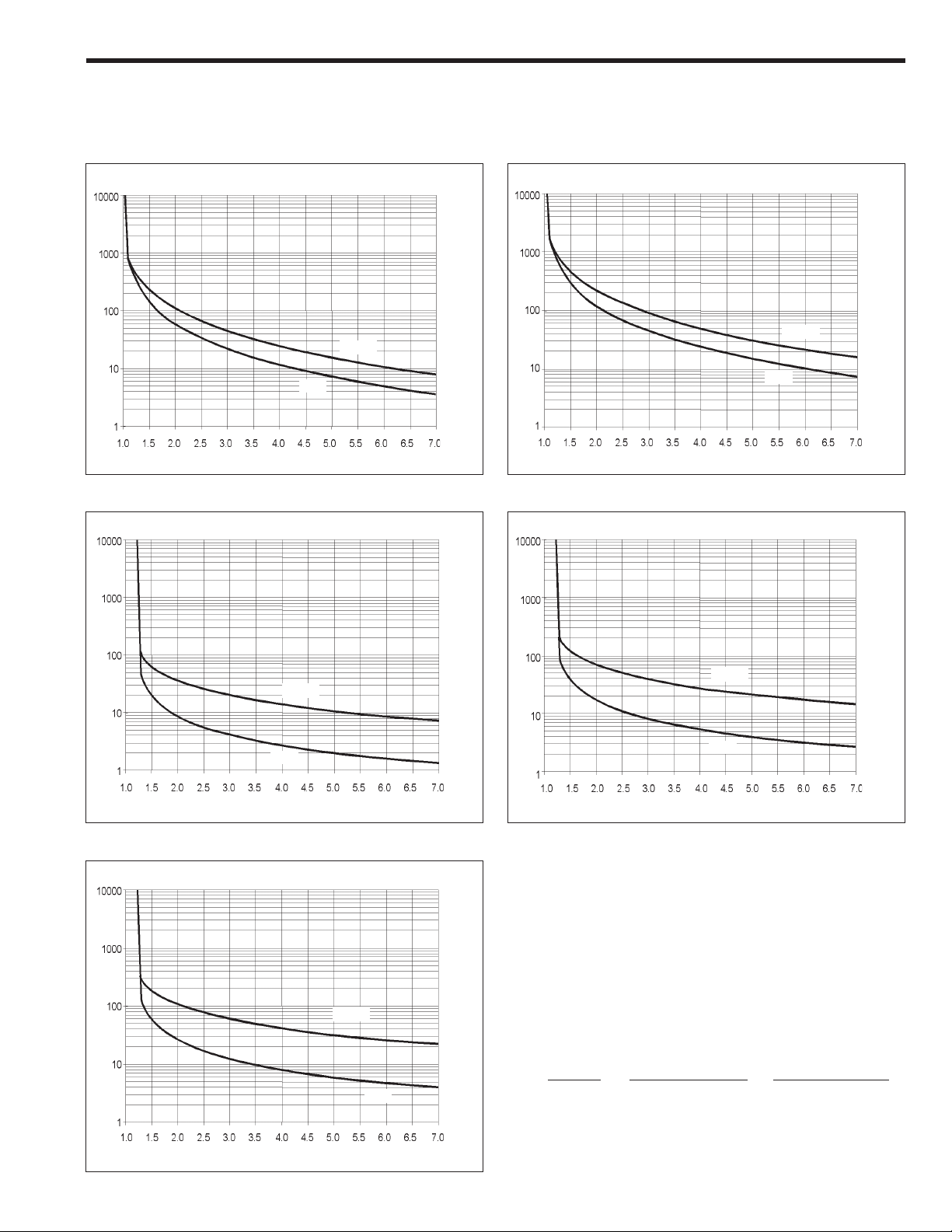
2-3. AST AT®-CD Plus, Thermal characteristics
The ASTAT-CD Plus allows the user to select motor protection according to IEC Class 10, 20 and NEMA 10, 20 or 30, selectable by "o" -overload- parameter
IEC Class 10 IEC Class 20
Sec. Sec.
COLD
COLD
HOT
Multiples of motor FLA rating In
NEMA 10 NEMA 20
Sec.
COLD
HOT
Multiples of motor FLA rating In
Sec.
HOT
Multiples of motor FLA rating In
COLD
HOT
Multiples of motor FLA rating In
NEMA 30
Sec.
COLD
HOT
Multiples of motor FLA rating In
Thermal memory:
If the control voltage is not removed, the unit has a cool down
characteristic. The time for cool down is 300 sec. after the overload trip.
If the control voltage is removed after tripping, you must wait at least 2
minutes before the unit can be restarted.
Operations per hour:
Using a cycle T, with starting time of t1, running time of T-2t1 at rated
current and OFF time of t1 sec. (minimum), the ASTAT-CD Plus allows
the following operations per hour.
Starting Operations / Hour. Operations / Hour
Current Starting time t1= 10sec. Starting time t1=20 sec.
2 Ir 180 90
3 Ir 160 60
4 Ir 30 10
2-3
Page 10

3. Technical Specifications
3-1. ASTAT®-CD Plus, General specifications
Voltage Ratings 3ph AC Systems
Freq. Range 50/60 Hz Control range of 45-65 Hz
Control Control system Digital system with microcontroller
Specifications Starting ramp with progressive increase in voltage and current limitation
Initial voltage (pedestal) % 30 - 95 U
Starting torque % 10 - 90 M
Kick start % 95 Un (90% M
Motor unit ratio (N) 0.4 - 1.2
Current limit (starting) 1 to 4.5 (Ir/In) Max 7.0 I
Acceleration ramp time s 1 to 99 (types: standard or linear ramp up)
Energy savings Output voltage reduction according to power factor
Override Fixed output voltage permanently equal to supply voltage
Bypass Direct control of a bypass contactor
Brake time by ramp s 1 to 120 (1 to 99 in secondary ramp) adjustable independently of starting ramp time (types: standard,
DC braking 0 to 99 s.; 0.0 to 2.5xI
Slow speed Direct torque: 7% or 14% of nominal speed; reverse torque: 20% of nominal speed
Retry 0 to 4 attemps, and 1 to 99 sec. retry time
Monitoring Motor current, line voltage (1), power, power factor and elapsed time
Running External control Start - Stop
Acceleration phase Adjustable time
Permanent phase Energy savings / Override choice
Stop phase Power cut-off / Ramp / DC braking/Pump control
Inputs / Outputs Inputs 4 digital optocoupled. Two fixed (Start , Stop), and 2 programmable (I3, I4)
Outputs 3 programmable relays (1r, 2r, 3r)
Up to 500V,
1 Analog 0-5VDC for Tachogenerator input feedback
1 Analog 0-10VDC output for current metering
+10%, -15% for
n
direct start
direct start
pump control or linear ramp down)
QC2xDP ASTAT-CD Plus series
), adjustable 0 to 999 ms
n
n
I Actual measured motor current
I
m
I
n
I
r
L Current limit for starting Im/I
L
max
M
direct start
NI
SF Service factor
U
n
Abbreviations
Maximum starting current desired
Nominal motor nameplate FLA
ASTAT rated nameplate FLA
450/N
Full voltage starting torque
n/Ir
Full line voltage
r
Protections Current limit Adjustable from 1 to 4.5 (Ir/In) Max 7.0 I
Overload IEC class 10 and 20 ; NEMA class 10, 20 and 30 all selectable
Cool-down time after
overload trip s 300 for reset
Loss on input phase s Trip at 3
Thyristor short circuit ms Trip at 200
Heatsink overheating ms Trip at 200
Motor thermistor ms Trip at 200 if thermistor impedance > response value
Loss on output phase s Trip at 3
Stalled rotor ms Trip at 200
Supply frequency error Hz If f < 45 or f > 65, will not start
Overcurrent 100 to 150% In; trip time adjustable from 0 to 99 sec.
Undercurrent 0 to 99% In; trip time adjustable from 0 to 99 sec.
Overvoltage (1) 100 to 130% Un; trip time adjustable from 0 to 99 sec.
Undervoltage (1) 0 to 50% Un; trip time adjustable from 0 to 99 sec.
Error (CPU) ms 60
Memory 4 former errors
Long start time s 2 x ta (ta = acceleration ramp time)
Long slow speed time s 120
Environmental Temperature °C 0 to +55 (derate output current by 1.5% / °C above 40°C)
conditions Relative humidity % 95% without condensation
Maximum altitude m 3000 (derate output current by 1% / 100m above 1000m)
Mounting position Vertical
Protection Degree IP00, UL Open
Standards CE, cUL, UL CE Conforming IEC 947-4-2; UL, cUL conforming to UL508
Conducted & radiated emissions Conforming IEC 947 -4-2, Class A
Electrostatic discharges Conforming to IEC 1000-4-2, level 3
Radioelectric interference Conforming to IEC 1000-4-6, level 3 and to IEC 1000-4-3, level 3
Immunity to fast trasients Conforming to IEC 1000-4-4, level 3
Immunity to Surge Voltage Conforming to IEC 1000-4-5, level 3
n
Note: (1) Monitors L1
3-1
Page 11
3. Technical Specifications
3-2. I/O Terminal board specifications
Power I/O terminals
Terminal Function Description
1L1, 3L2, 5L3 Mains Input 3ph input voltage 200-480 volts QC2xxx type
2T1, 4T2, 6T3 Motor output Output terminals to 3ph AC motor
A1, A2, B1, B2 Input Control Voltage 110/120V AC, +10%, -15% 220/240V AC, +10%, -15%
Digital Inputs
Terminal Function Description
57 Common for digital inputs This is a common terminal for the digital input terminals specified below.
1 Run Run order. Command signal may be provided by one NO dry momentary contact to terminals 1 and 57.
2 Stop Stop order. Command signal may be provided by one NC dry momentary contact to terminals 2 and 57.
NOTE: Run/Stop permanent command allows linking 1-57 and using one dry NO contact to 2-57
terminals.
3 Programmable input I3 These two inputs are programmable. They can be assigned to the following internal functions:
4 Programmable input I4
-soft stop -DC brake -Linear ramp
-pump control -slow speed control -dual ramp selection
-kick start -reverse slow speed -bypass function
-override -local / remote control
Command signal should be provided by one NC dry contact to terminals 57-3 or terminals 57-4. By switching
this contact ON / OFF it is possible to enable or disable the assigned function.
Digital Outputs
Terminal Function Description
11, 12, 14 Programmable relay 1r 11-12 = NC, 11-14 = N.O. dry contacts. This relay can be assigned to several internal
As default assigned to function RUN
23, 24 Programmable relay 2r 23-24 = N.O. dry contact. This relay can be assigned to several internal output functions (page 3-6).
As default assigned to function EOR
33, 34 Programmable relay 3r 33-34 = N.O. dry contact. This relay can be assigned to several internal output functions (page 3-6).
As default assigned to function DC BRAKE
Common for all relay output contacts Maximum usage voltage: 380VAC (B300-UL)
Thermal current: 8A
AC-15 use: 220V / 3A, 380V / 1A
DC-15 use: 30V max/ 3.5A
Analog I/O
Terminal Function Description
8 Analog input common (-) This is a common terminal for the analog input terminal number 7 and analog output terminal number 9.
7 TG feedback input (+) 0-5V analog input for speed feedback. It should be provided by a DC tacho-generator coupled to the motor.
This speed feedback signal is required when the "linear ramp" function is used.
9 Current output (+) 0-10V DC analog Output for current measurement purpose. (1 x Ir = 2V DC output)
Load Impedance 10KΩ or higher.
Motor thermistor terminals
Terminal Function Description
5 , 6 Motor thermistor input This input allows a motor thermistor with a response value from 2.8 to 3.2KΩ , and a reset value from 0.75 to
1KΩ to control motor temperature.
When the motor thermistor is not used, a link must be used between terminals 5-6.
output functions (p. 3.6).
Communications
Terminal Function Description
TD, RD, SG Tx, Rx, Gr data RS232C, 3 wires, half duplex. Maximum cable length 3meters (10 feet).
Asynchronous data transmission, 9600 Bauds, 1 bit start, 8 bits data, 2 bits stop, no parity.
3-2
Page 12
3. Technical Specifications
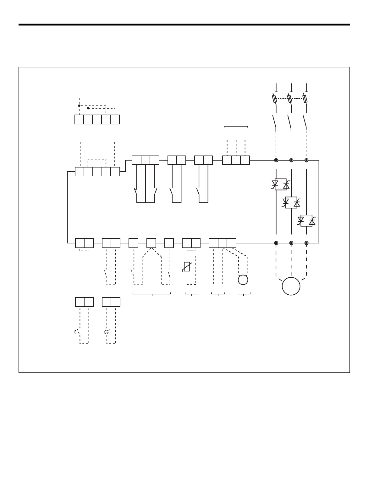
3-3. I/O wiring
ASTAT-CD Plus terminal layout and wiring configuration is shown in the diagram below
Control Voltage
110 / 120V AC
L1 L2 L3
(1*)
A1A2 B1B2
Control Voltage
220 / 240V AC
A1A2 B1B2
57 57 57 6 8
12
(Permanent Command)
Start /Stop
12 11 14
1r 2r 3r
Programmable Relay Outputs
Programmable Inputs
I3 I4
23
24
(2*)
33
3457
34
(3*)
+-
Serial Comm.
RS232C
Tx Rx Gr
RDSG
TD
9
-+
V
(1*)
1 L1 3 L2 5 L3
2 T1 4 T2 6 T3
M
3 ~
57 57
1 2
Input
Analog Input
Motor Thermistor
Tacho feedback
Start Stop
(Command by push-buttons)
(4*)
Inputs
Programmable
(4*)
Notes: (1) Control and Mains wiring recommendations are given in chapter 5.
(2) The programmable inputs I3, I4 are not assigned to any function as default. Check pages 3-6 prior to using these inputs.
(3) The programmable relay outputs are assigned to the following functions as default:
Relay (1r): RUN, (RUN status)
Relay (2r): EOR, (End of Ramp)
Relay (3r): DCBR, (DC Braking control)
(4) Important: Use dry contacts only
0-10V
Analog Output
3-3
Page 13

3-4. Operating modes
Starting and Stopping
3. Technical Specifications
Initial ramp
Initial voltage (pedestal)
Kick start
Acceleration ramp
Current limit
Permanent state
Stopping modes (All selectable)
1
1a
2
3
3a
4
5
5a
6
7
8
8a
5 main frequency cycles
30 to 95% Un (adjustable via initial torque setting T)
95% Un. Enabled by parameter "Pxxx" to ON, 0-999 ms (adjustable)
1-99 sec (adjustable). Dual ramp option.
Linear speed ramp by tacho feedback also possible
Fast ramp (if motor is up to speed before end of normal ramp time
100% to 450% x Ir/I
Max 700% I
n
n
)
Rated voltage (override)
Rated current
Energy savings. Enabled by "Fxxx" to OFF
Motor power cut-off. "Sxxx" to OFF, "Cxxx" to OFF
Deceleration ramp 1-120 sec (adjustable). Secondary ramp 1-99 sec
Ramp down modes available are:
- Soft Stop -Voltage ramp down-. Enabled by "Sxxx" to ON
- Pump control. Selectable by "Sxxx" to ON and "Cxxx" to ON
- Linear ramp down (Tacho feedback needed)
Evolution of current in deceleration ramp mode
Starting by voltage ramp
Override
U/Un
2
1A
1
3A
3
3
Energy savings
U/Un
1
2
1A
1
3A
3
3
9
DC brake (0-99 sec adjustable). Enabled by "Bxxx" to ON
Starting by current limitation
Override
5
8
7
9
9
t
l/ln
1
4
5a
7
8a
9
9
t
Energy savings
l/ln
6
7
8
9
9
t
4
8a
6
9
7
9
t
3-4
Page 14

Jog and linear ramp
T
3. Technical Specifications
Linear acceleration and deceleration ramp Ramp time adjustable (Selectable by parameter "Dxxx" to ON
Low slow (7%) and High slow (14%) speeds Enabled by parameter "Jxxx" to ON and "jxxx" to LO or HI
Reverse slow speed (20%) Enabled by parameter "Jxxx" to ON and "rxxx" to ON
Slow speed (7% or 14%) Enabled by parameter "Jxxx" to ON
Acceleration ramp Ramp time adjustable
Soft stop (deceleration ramp) Ramp time adjustable
Slow speed (7% or 14%) Enabled by parameter "Jxxx" to ON
DC Brake Current and time adjustables, Enabled by parameter Bxxx to ON, and bxx, Ixxx adjustments
Linear ramp with T.G. feedback
100
11a
% of motor full load speed
1
2
3a
4
5
6
7
8
1a
3
Slow speed. Basic diagram
100
14
7
% of motor full load speed
t
20
3
2
3a
t
Slow speed. Full diagram
100
% of motor full load speed
ERMINALS
CLOSED
4-57
OPEN
CLOSED
1-57
OPEN
CLOSED
2-57
OPEN
5
4
6
7
8
t
t
3-5
Page 15

3. Technical Specifications
3-5. Programmable Inputs and Outputs
Programmable inputs and functions
The ASTAT-CD Plus functions such as soft stop, kick start, etc., can be enabled (ON) or disabled (OFF) in their dedicated parameters by using the keypad.
Most of these functions can be enabled or disabled remotely as well, through the programmable inputs I3 or I4 (terminals 3-57 and 4-57).
Function Parameter
Soft Stop
Pump Control
Kick Start
Override
By-pass
DC Brake
Linear Ramp
(Jog). Slow Speed
Reverse Jog
Dual Motor
Remote Control
S xxx
C xxx
P xxx
F xxx
z xxx
B xxx
D xxx
J xxx
r xxx
A xxx
X xxx
More than one function can be enabled in the ASTAT-CD Plus, either by the keypad or through the programmable inputs I3 and I4, but there are some functions
which may not work as expected during stopping, such as when they are simultaneously enabled. When two or more of the below functions are simultaneously
enabled, the priority is defined in the following table:
Set Value
_OFF
_ON
_I3
_I4
<Remarks>
The function is permanently disabled
The function is permanently enabled
The status of the function depends upon I3 input
The status of the function depends upon I4 input
NOTE: One programmable input may enable or
disable more than one function
Condition Action
○○○○○○○○
○○○○○○○○
○○○○○○○○
DC Brake (B=ON) abc
Linear Ramp (S, D=ON) a aa
Soft Stop (S=ON) b a c
○○○○○○○○○○○
○○○○○○○○○○○
○○○○○○○○○○○
a The unit stops by Linear Ramp
b The unit stops by DC brake after the Soft Stop is completed.
c The unit stops by Pump Control
Pump Control (S, C=ON) c a c
DC Brake (B=ON)
Linear Ramp (S, D=ON)
Soft Stop (S=ON)
Pump Control (S, C=ON)
Programmable Relay Outputs
The ASTAT-CD Plus includes three programmable relays 1r, 2r and 3r (dry contacts). ASTAT-CD Plus terminals are 11-12-14, 23-24 and 33-34
These relays can be assigned to several functions, as shown below.
Relay N#
Relay 1r
Relay 2r
Relay 3r
Parameter
1r xx
1r xx
3r xx
Set Value
20
21
22
23
24
25
26
27
28
29
30
EOR Detects end of voltage ramp. -This function can only be assigned to relay 2rDC Brake DC Brake command -This function can only be assigned to relay 3rFault Detects ASTAT-CD Plus fault status
Undervoltage Detects limit set in parameter UVxx (1)
Overvoltage Detects limit set in parameter OVxx (1)
RUN Detects ASTAT-CD Plus run status
JOG Detects Jog (slow speed) status
Undercurrent Detects limit set in parameter UCxx
Overcurrent Detects limit set in parameter OCxx
Disabled Disables the relay function
Future use
<Remarks>
Note: (1) Monitors L1
3-6
Page 16

4. Programming
4-1. Keypad and display description
1
2
C / V
Display
Display Structure
Function code
FVVV
1
Data
Keypad
C / V
Displays monitoring, status indications, error messages and function set values
FVVV Status code
ON Equipment is
STOP Stop
LOCK Remote stop
PULS Kick start
RAMP Acceleration ramp
FULL Full conduction or
SAVE Energy saving
SOFT Soft stop
PUMP Pump control
DCBK DC braking
INCH Inching / slow speed
TACH Linear ramp (tacho)
2
Allows setting of parameters and functions
SELECTION
Use with
or
be displayed and/or modified
to select the parameter or function code to
connected
to main supply
(equipment is ON)
Override
FVVV Error code
E010 Frequency out of range
E011 Overload trip
E013 Loss of synchronism
E014 Phase U scr
E015 Phase V scr
E016 Phase W scr
E017 Heatsink overtemperature
E018 Motor thermistor
E019 Phase U lost
E020 Phase V lost
E021 Phase W lost
E022 Stalled rotor
E023 Internal error
E025 Long start time
E026 Long slow speed time
E027 Lock-out
E028 Undervoltage
E029 Overvoltage
E030 Undercurrent
E031 Overcurrent
E032 Retry, attempts exceeded
SEARCH / ADJUSTMENT
Decreases the value of the selected parameter
FF/V V V Function code (*)
Mx x x Motor current
vxxx Software version
. .
. .
PFxx Power factor
. .
. .
Lxxx Current limit
Txxx Starting torque
axxx Ramp up time
dxxx Ramp down time
Sxxx Soft stop selection
..
. .
LKxx Lock out
..
. .
(*) These are examples. Full details in sections
4-2, 4-3, 4-4, 4-5 and 4-6
SEARCH / ADJUSTMENT
Increases the value of the selected parameter
ENTER / SAVE
-Introduces the new parameter value into memory
- Updates the selected parameter value with the
displayed value
4-1
Page 17

4. Programming
4-2. Parameter block configuration
Mode Selection
The ASTAT-CD Plus includes a large number of parameters which are divided in four
blocks: Monitor, Calibration, Basic and Advanced. The parameters of each group can be
displayed or skipped according the selection done in parameter "G".
The monitor parameters are always displayed regardless of the mode selected
Monitoring
Parameters
G ALL
G CAL
Calibration
Parameters
Settings in parameter "G" GCAL The Calibration parameters are displayed
GBAS The Basic parameters are displayed
GADV The Advanced parameters are displayed
G BAS
Basic
Parameters
GALL All parameters are displayed
G ADV
Advanced
Parameters
Searching and Setting Parameters
The ASTAT-CD Plus displays the parameters sequentially while depressing the key and pushing repeteadly or keys. Proceed in this way
untill the parameter "G" is displayed.
There is a quick way to search automatically the parameter "G" by pressing and Keys. "Gxxx" will be shown on the display.
Once the parameter "G" is displayed, choose the value desired by pressing or Keys. The display will sequence "GBAS", "GCAL", "GADV" and
"GALL" values repeatedly. The actual value displayed can be stored in a temporal memory buffer by pressing key.
Values stored in the temporal memory are lost upon control power loss, unless saved in the permanent E2PROM memory through parameter "W". Additional
instructions are given on page 4-9.
The above is an example given for parameter "G", but all ASTAT-CD Plus parameters can be modified from its default factory value in a similar way.
C / V
C / V
Parameter layout
Monitor parameters
Status
M
v
V
C / V
+
PF
w
E
e
K
W
G
Shown automatically ON, STOP, LOCK, PULS, ...
Motor current
Software version
Line voltage
Line power factor
Line power
Elapsed time
Fault history buffer
Password
E2PROM writing
Parameter block selector
GBAS
GADV GALL
12
(see page 4-4)
e0, e1, e2, e3
GCAL
Calibration parameters
U
Line voltage
t
Voltage calibration
Unit frame
UF
Current calibration
m
N
Motor unit ratio
o
Overload protection
Service factor
f
100-500
0-600
F,G ,H , ... ,X
0-1300
40-120
0, N1, N2, N3,C1,C2
100-130
4-2
Page 18

4. Programming
1
Basic Parameters
L
Current limit
T
Starting torque
Ramp up time
a
d
Ramp down time
p
Kick start
b
DC brake time
DC brake current
I
S
Soft stop switch
Pump control switch
C
Pump curve selection
ST
starting
Pump curve selection
SP
stopping
Kick start switch
P
Override switch
F
By-pass switch
z
B
DC brake switch
(1) 100-450 (Ir/In) ; 700 max.
Unit
%
%
sec.
sec.
ms
sec.
%
Range
100-700 (1)
010-090
01-99
01-120
000-999
000-099
000-250
OFF, ON, I3, I4
OFF, ON, I3, I4
00-03
00-05
OFF, ON, I3, I4
OFF, ON, I3, I4
OFF, ON, I3, I4
OFF, ON, I3, I4
PON, PI3, PI4
2
Advanced Parameters
LK
Lock-out
R
E2PROM reading
Factory settings
Q
Y
Retry
y
Retry time
UV
Undervoltage
Undervoltage trip time
uv
OV
Overvoltage
ov
Overvoltage trip time
UC
Undercurrent
uc
Undercurrent trip time
Overcurrent
OC
Overcurrent trip time
oc
2a
Secondary ramp up
2d
Secondary ramp down
Secondary starting torque
2t
Tacho control switch
D
J
Slow speed switch
j
Low / High slow speeds
r
Reverse slow speed
Dual motor switch
A
X
Remote control switch
Comm protocol selection
XP
Unit
minutes
n. attempts
sec.
%
sec.
%
sec.
%
sec.
%
sec.
sec.
sec.
%
Range
00-45
ON, OFF
ON, OFF
000-004
001-099
00-50
00-99
00-30
00-99
00-99
00-99
00-50
00-99
01-99
01-99
10-90
ON, OFF, I3, I4
OFF, I3, I4
LO, HI
OFF, ON, I3, I4
OFF, ON, I3, I4
OFF, ON, I3, I4
00-02
4-3
s
1r
2r
3r
Station number
Output relay 1r
Output relay 2r
Output relay 3r
001-247
22-30
20, 22-30
21, 30
Page 19

4-3. Monitor block parameters
4. Programming
Display
ON
M xxx
v xxx
V xxx
PFxx
Function
Status
Motor current
Software version
Main source voltage (1)
Power factor
Default Range Unit
ON
ON
STOP
LOCK
PULS
RAMP
FULL
SAVE
SOFT
PUMP
DCBK
INCH
TACH
000-999
1.0-9.9
-
-
00-99
-
-
-
-
-
-
-
-
-
-
-
-
A
kA
%
-
V
%
Description
Switch on time. Equipment is connected to main supply
Stop
Remote control through serial port
Kick start
Acceleration ramp
Full conduction / Override (full voltage)
Energy saving
Soft stop
Pump control
DC braking
Inching / slow speed
Linear ramp (tacho feedback needed)
Displays motor current in Amps.
Current higher than 999A is displayed in kA.
If parameter UFxx is not calibrated, the motor current is
displayed in % I
xxx = Version number.
Displays line voltage in Volts.
Displays line Power Factor.
n
w xxx
E xxx
e xxx
K xxx
W xxx
G xxx
Note:
(1) Monitors L1
Line power
Elapsed time
Error trace buffer
Password
E2PROM writing
Parameter display
selection
K 000
W OF F
G BAS
-
-
e0xx-e3xx
000-999
ON, OFF
CAL, BAS, ADV,
ALL
kW
Displays Line Power.
Hrs
Displays RUN time in Hours (x 1000)
-
Saves the last four errors:
e0xx: Fault 1 -Latest fault- xx: Fault code error
e1xx: Fault 2
e2xx: Fault 3
e3xx: Fault 4
-
= 69 allows E2PROM writing operation
= 10 Key lock enabled
= 20 Key lock disabled
-
Saves the unit current parameters to the E2PROM.
This rewrites the last values saved. (Password 69 required)
-
CAL: Displays Calibration Parameters
BAS: Displays Basic Parameters
ADV: Displays Advanced Parameters
ALL: Displays All parameters
4-4
Page 20

4. Programming
4-4. Calibration block parameters
FunctionDisplay
U xxx
t xxx
UF x
m xxx
N xxx
o xxx
Line voltage setting
Voltage calibration
Unit frame
Current calibration
Motor rated current
Overload protection
-CAL-
Default Range Unit
U 480
t 480
UF 0
m 000
N 100
o N2
100-500
000-600
F, G, H, I, J, K, L,
M, N, Q, R, ...X
000-1300
040-120
OFF
N1, N2, N3,
C1, C2
Description
Line Voltage from 200 to 500V. Set rated value.
V
Setting of this parameter allows better accuracy in
V
monitoring and voltage protections (see the voltage
calibration procedure).
Unit frame rating (F,G,H,...X).
Setting “0” disables current calibration.
Setting of this parameter allows better accuracy in
A
monitoring and current protections (see the current
calibration procedure).
100 x (In/Ir)
%
When this parameter is adjusted at a value higher than
105% the overload protection curve is automatically
adjusted to Class 10. "C1" if Cx was selected, or to NEMA
20 "N2" if Nx was selected.
Selects either the following overload curves:
OFF: Overload protection disabled
(external overload relay must be used)
N1: NEMA 10
N2: NEMA 20
N3: NEMA 30 - (not available if N ≥ 105)
C1: Class 10
C2: Class 20 - (not available if N ≥ 105)
f xxx
Service factor
f 100
100-130
Motor service factor.
%
Voltage calibration procedure
When the ASTAT-CD Plus is installed on site for the first time or after the logic printed circuit board is replaced, the voltage measurements will have
an accuracy of ±10%. To improve the voltage measurement accuracy up to ±3%, proceed as follows:
1. Turn the ASTAT-CD Plus ON and measure the RMS voltage on phases 1L1-3L2 using a calibrated voltmeter.
2. Search for the parameter “txxx”, set the measured voltage, and save this value by depressing the enter key. It is not necessary to save
this to the E2PROM, as the ASTAT-CD Plus does this automatically. NOTE: Set the actual, measured voltage while the ASTAT-CD Plus is
ON. DO NOT enter the motor nameplate voltage rating.
3. Once the ASTAT-CD Plus has been calibrated, this operation does not need to be repeated unless the logic printed circuit board has
been replaced or the ASTAT-CD Plus has been installed into a new application. NOTE: The parameter “txxx” will show the latest
calibration entry, which may differ from the actual voltage value.
Current calibration procedure
When the ASTAT-CD Plus is installed on site for the first time or after the logic printed circuit board is replaced, the current measurements will have
an accuracy of ±10%. The internal electronic overload protection is also affected by this procedure. To improve the current measurement accuracy
up to ±3% and to improve the accuracy of the motor overload protection, proceed as follows:
1. Search for the parameter “UF_ x” and enter the correct ASTAT-CD Plus frame type letter (“F”,”G”,”H”,..etc.).
2. Start the motor and measure the rms motor current using a calibrated ammeter. This measurement should be done at full load and full
speed and after the motor current has stabilized.
3. Search for the parameter “mxxx”, set the measured current and save this value by depressing the enter key. It is not necessary to save
this to the E2PROM, as the ASTAT-CD Plus does this automatically. NOTE: Set the actual rms measured current while motor is running
at full speed and under full load. DO NOT enter the motor nameplate current rating.
Once the ASTAT-CD Plus has been calibrated, this operation does not need to be repeated unless the logic printed circuit board has been replaced or
the ASTAT-CD Plus has been installed into a new application. NOTE: The parameter “mxxx” will show the latest entry, which may differ from the
actual current value.
4-5
Page 21

4. Programming
4-5. Basic block parameters.
-BAS-
4-5-1. Basic Functions
Display
L xxx
T xx
a xx
d xxx
p xxx
b xx
I xxx
Note: (1) Parameters "p ", "b " and "I " are disabled while "C" is ON.
Function
Current limit
Starting torque
Ramp up time
Ramp down time
Kick start (1)
DC Brake time (1)
DC Brake Current (1)
Default Range Unit
L 400
t 25
a 15
d 020
p 000
b 00
I 050
100-L
10-90
01-99
001-120
000-999
00-99
000-250
max
Description
Sets Device current limit. Sets motor starting current limit
%
if parameter "N" is properly adjusted.
The maximum range setting is automatically calculated
by the unit according the following expression:
L
450 (Ir/In); Max. 700
max=
Sets the initial voltage applied to the motor.
%
Sets Voltage ramp up time. Motor acceleration time will
sec.
depend of load conditions.
Sets Voltage ramp down time. Motor deceleration time
sec.
will depend of load conditions.
Enabled only if the parameter "Sxxx" is ON.
During the time adjusted, provides 95% of full voltage to
ms.
motor at starting time. Useful for high static-friction loads
Enabled only if the parameter "Pxxx" is ON.
Provides DC braking at stopping time.
sec.
Enabled only if the parameter "Bxxx" is ON.
% I
%
n
4-5-2. Programmable basic functions
Display
S xxx
C xxx
STXX
SPXX
P xxx
Function
Soft stop selector
Pump control selector
Pump curve selection
at starting phase
Pump curve selection
at stopping phase
Notes:
- Curve 0 (both ST00, SP00): Standard voltage ramp up -starting- and ramp down -soft stop-
- Curve 1 (both ST01, SP01): Pump Algorithm based on estimated average PF -power factor- , with large sampling period.
- Curve 2 (both ST02, SP02): Pump Algorithm based on instantaneous PF with short sampling period.
- Curve 3 (both ST03, SP03): Pump Algorithm based on estimated average PF with short sampling period. Application: low pressure
- Curve 4 (SP04): Same as Curve 3, but with higher accuracy on PF average estimation. Application: high head pressure/low flow rate change.
- Curve 5 (SP05): Pump Algorithm based on former ASTAT-CD.
Kick start selector
Default Range
S OF F
C OF F
ST02
SP02
system/low flow rate change.
P OF F
OFF, ON, I3, I4
OFF, ON, I3, I4
00-03
00-05
OFF, ON, I3, I4
Description
Enables or disables all modes of Soft stop.
Enables the Pump control function. Usefull to limit fluid hammering.
The parameter "Sxxx" must also be enabled.
NOTE: Parameters "p ", "b " and "I " are disabled while "C" is ON
Choice of various pump control algorithms for starting:
0: Voltage ramp up 01-03: Various pump algorithms
Choice of various pump control algorithms for stopping phase:
0: Voltage ramp down 01-05: Various pump algorithms
Enables or disables the Kick start function.
If Pump control function “C” is enabled, both Kick start and DC Brake
functions are internally disabled.
F xxx
Override selector
F OF F
OFF, ON, I3, I4
4-6
When this function is enabled, the unit provides constant full voltage
after starting, producing the lowest harmonic distortion. Note that the
energy saving function is disabled when Override is enabled.
Page 22

4. Programming
Programmable Basic Functions (follow from previous page)
z xxx
B xxx
4-6. Advanced block parameters
By-pass selector
DC Brake selector
z OF F
B OF F
-ADV-
OFF, ON, I3, I4
OFF, ON, I3, I4,
PON, PI3, PI4
This function provides control of an external by-pass contactor,
significantly lowering heating losses and eliminating harmonics.
When the By-Pass function “z” is enabled, the programmable relay
output 2r is automatically assigned to this function, and must be used
to control the external by-pass contactor.
Enables or disables the DC brake function.
When the DC Brake function “B” is enabled, the programmable relay
output 3r is automatically assigned to this function.
PON, PI3 or PI4 settings enable the DC Brake function just before
starting the motor. This is usefull to stop a fan which is rotating in
reverse at the starting time.
4-6-1. Advanced functions
Display Description
LKxx
R xxx
Function
Lock-out
E2PROM reading
Default Range Unit
LK02
R OF F
00-45
ON, OFF
min.
-
Sets time between consecutive starts. Setting "0" disables
this function.
Loads the parameters from the E2PROM to the temporal
buffer.
Q xxx
Y x
y xx
UVxx
uvxx
OVxx
ovxx
UCxx
ucxx
OCxx
ocxx
Factory settings
Retry
Retry time
Undervoltage (1)
Undervoltage trip time
Overvoltage (1)
Overvoltage trip time
Undercurrent
Undercurrent trip time
Overcurrent
Overcurrent trip time
Q OF F
Y 0
y 10
UV00
uv20
OV00
ov20
UC00
uc20
OC00
oc20
ON, OFF
0-4
01-99
00-50
00-99
00-30
00-99
00-99
00-99
00-50
00-99
sec.
%
sec.
%
sec.
%
sec.
%
sec.
Loads default factory settings to the temporal buffer.
Resave to E2PROM if default settings are desired.
Allows up to four tries of automatic restart after a fault.
Setting “0” disables this function.
Time between retries.
The unit trips if the line voltage decreases below the
percentage set. Setting “0” disables this protection.
NOTE: Perform voltage calibration procedure on page
4-5 before enabling this protection.
Delay trip time.
The unit trips if the line voltage increases above the percentage set. Setting “0” disables this protection.
NOTE: Perform voltage calibration procedure on page
4-5 before enabling this protection.
Delay trip time.
The unit trips if the current decreases below the percentage set. Setting “0” disables this protection.
NOTE: Perform current calibration procedure on page
4-5 before enabling this protection.
Delay trip time.
The unit trips if the current increases above the percentage set. Setting “0” disables this protection.
NOTE: Perform current calibration procedure on page
4-5 before enabling this protection.
Delay trip time.
2axx
2dxx
2Txx
Note:
(1) Monitors L1
Dual ramp up
Dual ramp down
Dual starting torque
2a15
2d20
2T20
01-99
01-99
10-90
4-7
These are a secondary set of ramp up, ramp down and
%
starting torque parameters, which take over the primary
%
"a", "d" and "T" when the programmable function “A” is
%
enabled.
Page 23

4-6-2. Programmable advanced functions
4. Programming
D xxx
J xx x
j xx
r xxx
A xxx
X xxx
XPxx
s xxx
FunctionDisplay
Linear ramp
Slow speed
Speed changeover
Reverse
Dual motor selector
Remote control selector
Comunication protocol
Station number
Default Range
D OF F
J OF F
j LO
r OF F
A OF F
X OF F
XP00
s 001
OFF, ON, I3, I4
OFF, I3, I4
LO, HI
OFF, ON, I3, I4
OFF, ON, I3, I4
OFF, ON, I3, I4
00-02
001-247
Description
This function provides linear acceleration and deceleration ramps in
a wider range of load conditions using tachogenerator feedback.
A DC Tacho-Generator coupled to motor must be used to provide an
analog signal feedback of 0-5VDC to terminals 7 and 8.
This function enables slow speed operation
Maximum operation time 120sec.
LO: Low Speed, 7% of rated speed.
HI: High Speed, 14% of rated speed.
Reverse direction is allowed in "High slow speed" mode only.
It provides 20% of rated speed.
This function allows dual motor control settings of acceleration,
deceleration and starting torque, and is useful to start or stop a motor
in diferent load conditions.
When this function is enabled, the parameters 2a, 2d and 2T take
over the parameters a, d and T. It allows dual motor control settings.
Allows serial communication control by SG, TD and RD terminals.
Check Appendix section for more details
Sets serial communications protocol
0: ASCII 1: Future use
2: Future use
ASCII protocol allows a maximum of 90 stations only.
4-6-3. Programmable relay output functions
FunctionDisplay
1r xx
2r xx
3r xx
The programmable relays can be set to the functions shown in the following table:
Output relay 1r
Output relay 2r
Output relay 3r
Range
20
21
22
23
24
25
26
27
28
29
30
Function
EOR
DC Brake
FAULT
Undervoltage
Overvoltage
RUN
Slow Speed
Undercurrent
Overcurrent
Disabled
Future use
Default Range
1r 25
(RUN)
2r 20
(EOR)
3r 21
(DC Brake)
Remarks
Detects end of voltage ramp. -This function may only be assigned to relay 2r-
DC Brake control command -This function may only be assigned to relay 3r-
Detects unit Fault status. ON is normal status and switches OFF if a fault occurs
Detects Undervoltage according limit adjusted in function “UV”
Detects Overvoltage according limit adjusted in function “OV”
Detects unit RUN status
Detects slow speed status
Detects Undercurrent according limit adjusted in function “UC”
Detects Overcurrent limits as adjusted in function “OC”
Disables the relay function
22-30
20, 22-30
21-30
Description
This is a programmable relay with one NO / NC dry contact to
ASTAT-CD Plus terminals 11-12-14.
This is a programmable relay with one NO dry contact to ASTAT-CD
Plus terminals 23-24.
This relay is automatically assigned to BY-Pass control if the function “z”
is ON. Any other assignment by the user is overwritten in this case.
This is a programmable relay with one NO dry contact to ASTAT-CD
Plus terminals 33-34.
This relay is automatically assigned to DC-Brake control if the
function “B” is ON. Any other assignment by the user is overwritten in
this case.
4-8
Page 24

4. Programming
4-7. Application and basic settings
Different applications will require different characteristics and settings for the ASTAT-CD Plus. The table below lists typical settings for
various applications.
Settings (X X X)
Display
Parameters (1)
Nominal motor current N x x x 100
Current limit L x x x 400 375 400
Initial torque T x x x 025 030 035 020 020
Acceleration ramp time a x x x 015 015 030 030 015
Deceleration ramp time d x x x 020 040
Kick start time (2) p x x x 000 100
Soft stop S x x x OFF ON
Pump control C x x x OFF ON
Pump curve starting S T x x 02 02
Pump curve stopping S P x x 02 02
Kick start P x x x OFF ON
Overload trip curve(3) o x x x ooN2 ooN2 ooN2 ooC2 ooC1 ooC1
Service Factor(3) f x x x 100
Notes: (1) = GBAS Block Parameters unless noted(2)(3)
(2) = Parameter “p” is disabled while “C” is ON.
(3) = GCAL Block Parameters
Parameter
Factory
Default
Compressor
Mill Fan
Machine
Tool
Control
Pump
4-8. Saving parameters to E2PROM
Advance the display to K000 with
the C/V and up arrow button.
Change the parameter to K069 with
the up arrow button.
With K069 displayed, press the
enter button.
Display will show SET momentarily
and then display K ON.
Advance the display to WOFF with
the C/V and up arrow button.
Change parameter to W ON by using
the up arrow button.
With W ON displayed, press the
enter button.
Display the show SET momentarily
and then display WOFF.
4-9
Page 25

5. Installation
5-1. Equipment installation
CAUTION! DISCONNECT POWER BEFORE INSTALLING OR SERVICING
ONLY SPECIALIZED PERSONNEL SHOULD INSTALL THE EQUIPMENT AND ONLY
AFTER HAVING READ THIS USER'S GUIDE.
THE USER IS RESPONSIBLE FOR ANY PHYSICAL INJURY OR MATERIAL DAMAGE
RESULTING FROM MISHANDLING THE EQUIPMENT.
5-2. General
Terminal Connections
Use minimum of 75°C copper wire only for connections to ASTAT-CD Plus terminals. The minimum wire size must conform to the 75°C
table according to applicable electrical codes. Tighten connections to the torque values given below. Supply conductors should have, as
a minimum, the same cross section as a full voltage starter.
Catalog Numbers Wire Range Torque, in-lb
QC*FDP - QC*KDP #14 - #3 AWG 40
QC*LDP - QC*MDP #14 - #2 AWG 125
QC*NDP - QC*QDP #6 AWG - 350kcmil 275
QC*RDP - QC*SDP #2 AWG - 2x250 or 1x600kcmil 550
QC*TDP #4 AWG - 6 x350kcmil 275
QC*UDP #4 AWG - 4x250 or 2x600kcmil 550
QC*VDP #4 AWG - 3x600kcmil 500
Signal Wiring
Signal wiring should be no longer than 18 feet (up to 80 feet when
using shield cable). It must be separated from power wires (line,
motor, commands relays, etc.) by at least four inches and, if they
cross, they should do so at a 90° angle.
10 cm 8 cm
Coil Surge Suppression
Relays and contactors located in the same housing as the equipment
should have an RC suppressor parallel to the coil (or a reverse
diode, if controlled by DC).
SIGNAL
POWER
CORRECT INCORRECT
A A C D D C
Power Factor Capacitors
Do not install capacitors to correct the power factor between equipment output and motor.
Transformers
If the equipment is fed by a line transformer, its rated power should be at least 1.5 times, but less than 10 times, higher than equipment supply.
Environment
When installing equipment, keep the following points in mind:
- The equipment should be installed vertically and hang over a
platform or bars. The vertical position is essential for proper cool air
circulation.
- Environmental conditions are in accordance with the following
ranges and maximum values:
- Operating temperature: 0°C to +55°C
- Relative humidity (without condensation): 95%
- Maximum altitude: 3000m
Reduce rating by 1.5% / °C from 40°C and 1% / 100m from 1000m
- Do not install equipment in environments containing explosive or
flammable gases, or near important heat sources.
- Equipment should be well ventilated, with minimum keeping
clearances as indicated in the illustration.
- When equipment is to be mounted on a platform subject to strong
vibrations, there should be an elastic base to protect the equipment.
- When mounted in an enclosure, the temperature inside the enclosure
must be kept within the range of 0-45°C (32-113°F).
50mm 50mm
5-1
150mm
ASTAT
100mm
Page 26

5. Installation
5-3. Fuses, contactors and supply wiring
IEC Class 10
Ratings
Cat Number A W A mech. design) Size In A VA mm
QC _ F DP 17 67 25 6,600 CP URC 14.51/40 00 40 1 18 CL02 CL02 4
QC _ G DP 21 78 32 6,6 URD 30 XX 0063 00 50 1 18 CL03 CL03 4
QC _ H DP 27 88 40 6,6 URD 30 XX 0080 00 80 1 18 CL04 CL03 6
QC _ I DP 38 116 63 6,6 URD 30 XX 0100 00 100 1 18 CL45 CL04 10
QC _ J DP 58 208 80 6,6 URD 30 XX 0125 00 125 2 55 CL07 CL45 16
QC _ K DP 75 277 100 6,6 URD 30 XX 0160 00 160 2 55 CL08 CL06 25
QC _ L DP 86 302 125 6,6 URD 30 XX 0160 00 200 2 55 CL09 CL06 35
QC _ M DP 126 389 200 6,6 URD 30 XX 0250 00 250 2 55 CK75 CL07 50
QC _ N DP 187 719 250 6,6 URD 30 XX 0315 00 315 2 78 CK08 CL10 95
QC _ Q DP 288 1097 400 6,6 URD 31 XX 0500 2 550 2 78 CK95 CK85 185
QC _ R DP 378 1286 500 6,6 URD 31 XX 0630 2 630 4 118 CK10 CK85 240
QC _ S DP 444 1374 630 6,6 URD 32 XX 0800 2 800 4 118 CK11 CK95 Bus bar (1)
QC _ T DP 570 2086 800 6,6 URD 33 XX 1000 3 1000 4 118 CK12 CK10 Bus bar (1)
QC _ U DP 732 2352 1000 6,6 URD 33 XX 1250 3 1250 4 248 CK12 CK10 Bus bar (1)
QC _ V DP 1020 3000 1250 6,6 URD 233 XX 2000 - - 4 248 CK13 CK11 Bus bar (1)
QC _ X DP 1290 3839 2x800 6,6 URD 233 XX 2000 - - 4 248 CK13 CK12 Bus bar (1)
IEC Class 20
Ratings
Cat Number A W A mech. design) Size In A VA mm
QC _ F DP 14 56 20 6,600 CP URC 14.51/40 00 40 1 18 CL01 CL01 4
QC _ G DP 17 65 25 6,6 URD 30 XX 0063 00 50 1 18 CL02 CL02 4
QC _ H DP 22 74 32 6,6 URD 30 XX 0080 00 80 1 18 CL03 CL03 4
QC _ I DP 32 99 63 6,6 URD 30 XX 0100 00 100 1 18 CL04 CL04 6
QC _ J DP 48 178 80 6,6 URD 30 XX 0125 00 125 2 55 CL06 CL04 10
QC _ K DP 63 236 80 6,6 URD 30 XX 0160 00 160 2 55 CL07 CL04 16
QC _ L DP 72 257 100 6,6 URD 30 XX 0160 00 200 2 55 CL08 CL06 25
QC _ M DP 105 325 160 6,6 URD 30 XX 0250 00 250 2 55 CL10 CL06 35
QC _ N DP 156 591 200 6,6 URD 30 XX 0315 00 315 2 78 CK75 CL07 70
QC _ Q DP 240 901 315 6,6 URD 31 XX 0500 2 550 2 78 CK85 CK75 120
QC _ R DP 315 1063 400 6,6 URD 31 XX 0630 2 630 4 118 CK95 CK85 185
QC _ S DP 370 1136 500 6,6 URD 32 XX 0800 2 800 4 118 CK10 CK85 240
QC _ T DP 475 1721 630 6,6 URD 33 XX 1000 3 1000 4 118 CK11 CK95 Bus bar (1)
QC _ U DP 610 1950 800 6,6 URD 33 XX 1250 3 1250 4 248 CK12 CK10 Bus bar (1)
QC _ V DP 850 2491 1000 6,6 URD 233 XX 2000 - - 4 248 CK13 CK10 Bus bar (1)
QC _ X DP 1075 3168 1250 6,6 URD 233 XX 2000 - - 4 248 CK13 CK12 Bus bar (1)
In Total Fuses Fuses Fuses Control voltage Contactor Contactor Conductor
losses aM FERRAZ type BUSSMANN type DC 1 DC 3 section
100% In (F1) (XX=according (Typower Sicu 660V~) Fuse Consumpt. (2)
In Total Fuses Fuses Fuses Control voltage Contactor Contactor Conductor
losses aM FERRAZ type BUSSMANN type DC 1 DC 3 section
100% In (F1) (XX=according (Typower Sicu 660V~) Fuse Consumpt. (2)
(1) As per IEC 947 (2) The 3 contacts of DC3 must be connected in parallel
2
2
Branch circuit protection, UL
Gould-Shawmut, semi-conductor fuses Short-Circuit Rating Max @480V
Type Type Rating Class Breaker Non-
Cat Number A50QS
QC _ F DP 50A - 30A 35A 25KA 5KA
QC _ G DP 60A - 35A 40A 25KA 5KA
QC _ H DP 80A - 40A 50A 25KA 5KA
QC _ I DP 100A - 70A 80A 25KA 5KA
QC _ J DP 150A - 100A 125A 25KA 10KA
QC _ K DP 200A - 125A 150A 25KA 10KA
QC _ L DP 225A - 150A 150A 25KA 10KA
QC _ M DP 350A - 200A 250A 25KA 10KA
QC _ N DP 450A - 350A 350A 65KA 25KA
QC _ Q DP 600A - 500A 600A 65KA 25KA
QC _ R DP 2X500A in parallel - 600A 700A 65KA 25KA
QC _ S DP 2x600A in parallel - 600A 800A 65KA 25KA
QC _ T DP - 2x1000A in parallel - 800A 65KA 30KA
QC _ U DP - 2x1200A in parallel - 1000A 65KA 30KA
QC _ V DP - 2x1600A in parallel - 1200A 65KA 65KA
1
A50P
2
Max. Fuse Max. Circuit
RK5 & J Size Combination Combination <Remarks>
(1) Suitable for use on a circuit capable of
delivering not more than 100KA RMS
symetrical amperes, for 208V, 240V and up to
480V maximum, when used with the semiconductor fuse for short-circuit protection. Listed
with Gould Shawmut Form 101, Type A5QS
or A50P.
(2) Suitable for use on a circuit capable of
delivering not more than 65KA RMS symetrical
amperes, for 208V, 240V and up to 480V
maximum, when used with contactors (isolation
*2
*2
or by-pass) that are also rated for 65KA
withstand.
NOTE: When ASTAT-CD Plus reduced voltage starters are used in conjunction with semi-conductor fuses, Type 2 Coordination to IEC 947-4 is attained. These
fuses are recommended for best overall short-circuit protection. The semiconductor fuse specified may provide branch circuit protection. Refer to local applicable
electrical codes.
5-2
Page 27

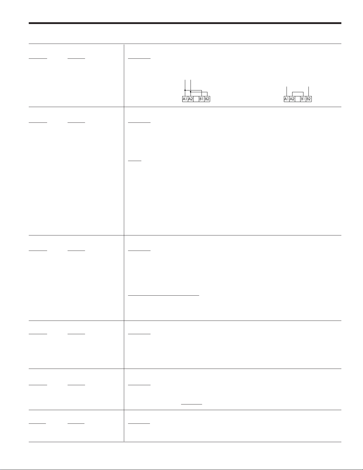
5-4. Start-up
- Make sure equipment wiring corresponds to one of
the recommended routing diagrams or equivalent.
- Make sure the control wire harness corresponds to the control voltage used.
5. Installation
- If the motor has thermal protection sensor, remove the link between
terminals 5 and 6 prior to wire the sensor
110/120V ac
A1 A2 B1 B2
220/240V ac
A1 A2 B1 B2
- Adapt equipment rated current to motor, setting
the motor current In.
In
N x x x ; x x x =
x 100
Ir
1. Enter the motor nameplate full load amperes: (I
2. Enter the ASTAT-CD Plus nameplate full load amperes: (I
3. Divide Line 1 by Line 2 and multiply by 100. This is your N parameter value. _________
4. Enter the facility or installation maximum allowable amperes: _________
5. Divide Line 4 by Line 1 and multiply by 100. This is your maximum allowable
L parameter value governed by facility limitations. _________
6. Divide 450 by Line 3 and multiply by 100. If the result is greater than 700, enter 700.
This is you maximum allowable L parameter value governed by ASTAT-CD Plus limitations. _________
7. Enter the value of Line 5 or Line 6, whichever is lower. This is your maximum
allowable L parameter value. _________
) _________
n
- Set starting parameters as needed:
L x x x = 450/N
L x x x =
Im (start)
In (motor)
x 100
Starting torque T _ x x T _ 2 5
Acceleration ramp time a x x x a _ 1 5
Kickstart P ON/OFF/I3/I4 P OFF
Kickstart time p x x x (if P enabled) p 0 0 0
Current limit L x x x L 4 0 0
- Set overload trip curve as needed:
oxxx ; xx x OFF = disabled (extermal overload relay must be used
C1/C2 = IEC Class 10 or Class 20
N1/N2/N3= Nema 10, 20 or 30
- Set braking parameters as needed:
Soft stop S ON/OFF/I3/I4 S OFF
Decceleration ramp time d x x x d _ 2 0
DC injection brake B ON/OFF/I3/I4 B OFF
DC braking time b _ x x (if B enabled) b 0 0 0
DC braking current I x x x (if B enabled) I 0 5 0
If you change the default configuration and wish
to keep it, remember to rewrite the parameters
in E2PROM as follows:
(See page 4-9 for details)
- Set parameter K to ON (ON = 69 + )
- Set parameter W to ON
- Press (parameter W is set to OFF automatically)
- Send run command to equipment and make sure that operation is correct.
) _________
r
Factory setting
N 1 0 0
Factory setting
Factory setting
o N2
Factory setting
5-5. Troubleshooting
Symptom or Error & (Error Code) Possible Cause Measures to be taken
Display OFF
Fans not running
Equipment does not respond to
STOP / START controls
Motor will not start but display shows –
Ramp, Full, etc.
No control voltage
Main breaker tripped or fuse blown
F1 fuse blown on power supply PCB
Bad connection of flat ribbon wire joining
power supply PCB to control PCB
No voltage to fans
F2 fuse blown on power supply PCB
No power to gate circuits
Check wire harness and control voltage
Check and change, page 6-10
Verify connectors
Check Power Supply Board and Logic Board
for 5VDC. Use a DC voltmeter on the Power
Supply Board, (-) lead of voltmeter on the top
lead of C6 (located next to the black heatsink
on the right edge of the Power Supply Board)
and the (+) lead of voltmeter on top lead of
Diode AD21 or R25 (located on the upper
right corner of the Power Supply Board).
Verify voltage and connections
Check and change, page 6-10
Check 12VDC on Power Supply Board. Use a DC
voltmeter on the Power Supply Board, (-) lead of
voltmeter on the top lead of C6 (located next to the
black heatsink on the right edge of the Power Supply
Board) and the (+) lead of voltmeter on bottom lead
of Diode AD20 (located near the lower left corner of
the black heatsink on the Power Supply Board).
5-3
Page 28

5. Installation
V
Symptom or Error & (Error Code) Possible Cause Measures to be taken
Frequency error (Ex10)
(admits 45Hz
≤
f main ≤ 65Hz)
Overload trip (Ex11)
Synchronism loss (Ex13)
Phase A, B, C thyristor (Ex14)
(Ex15)
(Ex16)
Heatsink thermostat (Ex17)
Motor thermistor (Ex18)
Phase A, B, C loss (Ex19)
(Ex20)
(Ex21)
Stalled rotor (Ex22)
No 1L1 phase or frequence is out of range
Excessive load or excessive current during
starting
Check 1L1 phase and/or mains frequence
Verify overload conditions during starting time and
steady state.
Check settings in parameters "Nxxx", "Lxxx", and "oxxx"
Phase 1L1 lost
Short circuited thyristor
Check 1L1 phase
Check thyristor module
Check ground connections and voltage to ground
Poor ribbon cable connection
No output phases
Heatsink thermostat tripped by overheating or
defective
Motor thermistor tripped by overheating or defective
Check 2T1, 4T2 and 6T3 phases
Check for adequate ventilation
Check thermostat and wiring
Check thermistor and wiring, if no thermistor
terminal 5 and 6 must be jumpered
No input / output phases
Check power wire harness for 1L1, 3L2, 5L3,
2T1, 4T2 and 6T3
Defective thyristor or ribbon wire harness
loose or defective
Equipment detected stalled motor rotor
Verify gate and cathode wire
harness. Verify thyristors
Restart equipment and check for an appreciable loss in
motor speed at any time
Internal error (Ex23)
Micro-controller malfunction
Check IC1 and IC8 are correctly inserted in their sockets.
Check for noise on control voltage power or line
Long start time (Ex25)
Current limit condition present more than
2 x ta sec. or 240 sec.
Increase current limit and / or acceleration
ramp time
(ta = acceleration ramp time)
Long slow speed time (Ex26) Reduce time slow speed is engaged
Equipment has been in slow speed mode more
than 120 sec.
Lock-out (Ex27)
The time between startings is less that the
adjusted in parameter "LKxx"
Undervoltage (Ex28)
Overvoltage (Ex29)
Undercurrent (Ex30)
Overcurrent (Ex31)
Retry (Ex32)
The line voltage exceeds of limit set in
parameters "UVxx" or "OVxx"
The motor current exceeds of limit set in
parameters "UCxx" or "OCxx"
The retry feature could not re-start the motor
after a fault
5-6. Thyristor check
S
hortcircuit
Use a testing lamp to check the defective power module between input and output phases.
If the lamp goes on, at least one of the thyristors has a short circuit.
With a tester, check the value or the R resistance between input and output of the same phase
(connector B on main PCB must be previously removed).
Check if settings are correct
This protection may be disabled
Check if settings are correct.
This protection may be disabled
Check if settings are correct.
This protection may be disabled
Check last message "e1xx" and correct.
Be sure that retry settings are correct as well.
1L1 (3L2 or 5L3)
Testing
lamp
3 to 6V
If R < 50KΩ, at least one of the thyristors is defective.
2T1 (4T2 or 6T3)
Open thyristor
S
With the simple assembly shown, the lamp should light when the S switch is closed and remain lit when open.
If not, the thyristor is defective.
5-4
10 ohms
L
3 to 6
Page 29

6-1. Application diagrams
Basic diagram
Control Voltage
110 / 120V AC
A1A2 B1 B2
Control Voltage
220 / 240V AC
12 11 14
A1A2 B1 B2
Programmable Inputs
57 57 57 6 8
12
I3 I4
3457
DC1
1r 2r 3r
Programmable relay Outputs
6. Appendix
REMARKS:
1) The isolation contactor DC1, is not required to perform
L1 L2 L3
DC1 (1)
23
33
24
RDSG
TD
34
9
1 L1 3 L2 5 L3
2 T1 4 T2 6 T3
(
operation to the motor.
Be aware however that DC1 provides galvanic
isolation from the incoming line increasing the safety.
(2) In this example, Start and Stop command is enabled
by push-buttons. Permanent command is allowed as
well, wiring 1, 2 and 57 terminals as shown on
page 3-3.
(3) The output relays allow for direct action on contactors
according to ratings specified on page 3-2 of this
manual.
(4) The ASTAT-CD Plus is provided with an electronic
motor overload protection, which should be adequate
protection for most of the applications.
An external overload should be used if required by
local codes or to protect the motor against current
unbalance.
Start
Push-Button command (2)
Stop
Motor Thermistor
Basic diagram with by-pass control
Control Voltage
110 / 120V AC
Control Voltage
A1A2 B1B2
Control Voltage
220 / 240V AC
A1A2 B1B2
57 57 57 6 8
12
Start /Stop
(Permanent Command)
57 57
1
Start Stop
(Command by push-buttons)
12 11 1423243334
1r 2r 3r
Programmable Relay Outputs
Programmable Inputs
I3 I4
3457
2
Programmable
Inputs
DC1
DC2
Input
Motor Thermistor
Serial Comm.
RS232C
Tx
TD
+-
Analog Input
Tacho feedback
Rx Gr
RDSG
9
-+
V
0-10V
Analog Output
M
3 ~
L1 L2 L3
1 L1 3 L2 5 L3
2 T1 4 T2 6 T3
M
3 ~
6-1
FLT (4)
M2
Bypass
REMARKS:
(1) The isolation contactor DC1, is not re-
quired to perform operation to the motor.
Be aware however that DC1 provides galvanic isolation from the incoming line increasing the safety.
(2) In this example, Start and Stop command
is enabled by permanent command. Pushbutton control is allowed as well, wiring 1,
2 and 57 terminals as shown on page 3-3.
(3) The output relays allow for direct action on
contactors according to ratings specified
in page 3-2 of this manual.
(4) CAUTION:
In by-pass mode an external overload
relay must be used.
(5) By-pass control using function "zxxx" and
external contactor DC2. Details given bellow.
By-pass control. Programming steps
1. The by-pass function may be enabled by
setting "zxxx" to ON. In this case the bypass is automatically done after starting.
An alternative, if "zxxx" is set to one of the
programmable inputs "I3" or "I4", the bypass may be controlled by one remote
signal (5). Check section 4-5-2 for more
details.
2. Once this function is enabled, the relay 2r
is automatically assigned to this function
(check section 4-6-3). This relay must be
used to control the by-pass contactor.
Page 30

6. Appendix
6-1. Application diagrams
Basic diagram with jog (slow speed) function
Control Voltage
110 / 120V AC
A1A2 B1B2
Control Voltage
220 / 240V AC
12 11 14
A1A2 B1B2
Programmable Inputs
57 57 57 6 8
12
Start
Push-Button command (2)
I3 I4
3457
Forward Reverse
Stop
Jog (Slow Speed)
DC1
23
33
24
1r 2r 3r
Programmable relay Outputs
Motor Thermistor
RDSG
34
TD
9
L1 L2 L3
1 L1 3 L2 5 L3
2 T1 4 T2 6 T3
M
3 ~
DC1 (1)
FLT (4)
REMARKS:
(1) The isolation contactor DC1, is not required to perform
operation to the motor.
Be aware however that DC1 provides galvanic isolation
from the incoming line increasing the safety.
(2) In this example, Start and Stop command is enabled by
push-buttons. Permanent command is allowed as well,
wiring 1, 2 and 57 terminals as shown on page 3-3.
(3) The output relays allow for direct action on contactors
according to ratings specified on page 3-2 of this manual.
(4)
The ASTAT-CD Plus is provided with an electronic motor
overload protection, which should be adequate protection for most of the applications.
You should use an external overload protection if
required by local codes or to protect the motor against
current unbalance.
(5) Slow Speed for Jog forward or reverse using program-
mable inputs I3, I4. Details given bellow.
Jog (Slow Speed) function. Programming steps
1. The slow speed function may be enabled by setting
"Jxxx" to I3. In this case Slow Speed is allowed by a pushbutton wired to ASTAT-CD Plus's terminals 3-57.
Reverse jog is also possible by setting "rxxx" to ON. As
alternative, if "rxxx" is set to programmable input I4,
forward or reverse may be controlled by remote pushbutton signal (5). Check section 4-6-3 for more details.
2. Slow Speed can be effected with ASTAT-CD Plus in stop
status. Slow speed and normal run commands are
internally interlocked.
Basic diagram with DC brake injection
Control Voltage
110 / 120V AC
A1A2 B1B2
Control Voltage
220 / 240V AC
A1A2 B1B2
57 57 57 6 8
12
Start /Stop (2)
(permanent Command)
FLT
DC1
12 11 14
Programmable relay Outputs
Programmable Inputs
I3 I4
3457
23
24
1r 2r 3r
Motor Thermistor
DC3
33
TD
34
RDSG
9
L1 L2 L3
1 L1 3 L2 5 L3
2 T1 4 T2 6 T3
DC3
M
3 ~
6-2
DC1 (1)
FLT (4)
REMARKS:
(1) The isolation contactor DC1, is not required to perform
operation to the motor.
Be aware however that DC1 provides galvanic isolation
from the incoming line increasing the safety.
(2) In this example, Start and Stop command is enabled by
permanent command. Push-buttons control is allowed
as well, wiring 1, 2 and 57 terminals as shown on
page 3-3.
(3) The output relays allow for direct action on contactors
according to ratings specified in page 3-2 of this manual.
(4)
The ASTAT-CD Plus is provided with an electronic motor
overload protection, which should be adequate protection for most of the applications.
An external overload relay should be used if required
by local codes or to protect the motor against current
unbalance.
(5) DC brake at stopping time is provided by the DC brake
function and external contactor DC3.
CAUTION:
The 3 contacts of DC3 must be connected in parallel.
Mandatory between 2T1 and 4T2 phases, otherwise a
short-circuit can occur
DC brake function. Programming steps
1. The DC function may be enabled by setting "Bxxx" to ON.
2. Once this function is enabled, the relay 3r is automatically
assigned to this function. This relay must be used to
control the DC brake contactor.
Check section 4-5-1 and 4-5-2 for more details
Page 31

6-1. Application diagrams
Basic diagram with linear ramp
Control Voltage
110 / 120V AC
A1A2 B1B2
Control Voltage
220 / 240V AC
12 11 14
A1A2 B1B2
Programmable Inputs
57 57 57 6 8
12
Start
Push-Button command (2)
I3 I4
3457
Stop
DC1
23
24
1r 2r 3r
Programmable relay Outputs
Motor Thermistor
6. Appendix
REMARKS:
L1 L2 L3
DC1 (1)
33
RDSG
34
TD
9
1 L1 3 L2 5 L3
2 T1 4 T2 6 T3
M
3 ~
FLT (4)
(1) The isolation contactor DC1, is not required to perform
operation to the motor.
Be aware however that DC1 provides galvanic isolation
from the incoming line increasing the safety.
(2) In this example, Start and Stop command is provided by
push-buttons. Permanent command is allowed as well,
wiring 1, 2 and 57 terminals as shown on page 3-3.
(3) The output relays allow for direct action on contactors
according to ratings specified in page 3-2 of this manual.
(4)
The ASTAT-CD Plus is provided with an electronic motor
overload protection, which should be adequate protection for most of the applications.
An external overload relay should be used if required
by local codes or to protect the motor against current
unbalance.
(5) Linear ramp provided by "Dxxx" function. A tacho
generator must be used as feedback. Details given
bellow.
Linear ramp function. Programming steps
1. The linear ramp function may be enabled by setting
"Dxxx" to ON. In this case, linear ramp is independent of
the load.
This function needs the speed feedback provided by an
external tacho generator. Check section 4-6-2 for more
details.
6-3
Page 32

6. Appendix
6-2. Serial communications
ASTAT-CD Plus is able to send and receive data through a serial RS232 port. Within this port ASTAT-CD Plus communicates with a host PC.
For RS232 ASCII communications, parameter "XP" must be set to 0.
6-2-1. RS232 port, wiring and communications settings
RS232 is an operating standard of communication only in terms of electrical characteristics (voltage, timing, etc.) while the communication
procedures are defined by ASCII.
The maximum allowed RS232 cable length is 3 meters. ASTAT-CD Plus uses a connector with only 3 pins: TD, RD, SG.
Astat Terminal Name
TD Transmit Data
RD Receive Data
SG Signal Common
Pin
Computer 2 TD ASTAT-CD Plus
RS232 connector 3 RD
D-SUB9 5 SG
RS232 cable
The following table indicates the communications setting used by ASTAT-CD Plus to perform data communication via its serial port.
Name Setting Description
Baud Rate 9600 bps Bits per second transmission rate
Parity None Data error checking method
Data Bits 8 Number of data bits in each transmission
Start Bits 1 Number of bits to indicate beginning of transmission
Stop Bits 2 Number of bits to indicate ending of transmission
Data ASCII Communications protocol used
Handshaking None No need to request to send or clear to send
6-4
Page 33

6. Appendix
6-2-2. ASCII protocol
To select this communications protocol, XP must be set to 0.
It is possible to operate the ASTAT-CD Plus from a host using standard ASCII characters. Two functions are available to be able to READ and
WRITE parameters.
Write Parameters to ASTAT-CD Plus:
To write data into a parameter, the command format is the following:
Request from host : :ssWxxxyyy➥
Response from the ASTAT : :ssWxxxyyy➥
where ‘:’ is a char to indicate the command start, ‘ss’ is the station address, ‘xxx’ (3 bytes needed) is the parameter number, and
‘yyy’ (3 bytes needed) is the value to write into the parameter. The ‘➥‘ is the return key to indicate the command stop.
Note: the parameters modification is not allowed while the motor is operating.
Read Parameters from ASTAT-CD Plus:
To read a parameter, the command format is the following:
Request from host : :ssRxxx➥
Response from the ASTAT : :ssRxxxyyyyy➥
where ‘:’ is a char to indicate the command start, ‘ss’ is the station address, ‘xxx’ (3 bytes needed) is the parameter number, and
‘yyyyy’ (5 chars response) is the value of the parameter. The ‘➥‘ is the return key to indicate the command stop.
Examples:
If we are trying to communicate with station 2:
- to start the unit, the command will be: :02W060000➥
- to stop the unit, the command will be: :02W060001➥
- to set the acceleration ramp time to 35 sec., the command will be: :02W005035➥
- to know which overload curve is selected, the command will be: :02R016➥ ; ( if, for instance the response is :02R01600004➥,
this means that the overload curve selected is IEC class 10 ).
The Table shown in 6-2-3 provides a complete reference for the parameters that can be controlled by the serial interface.
6-5
Page 34

6. Appendix
6-2-3. List of parameters that can be controlled by the serial interface
Parameter Parameter Function Read/Write Range Comments
number name (R/W)
0 Status Soft starter status R/ - 0 - 14 0: ON
1: STOP
2: LOCK
3: Alarm (errors)
4: PULS
5: RAMP
6: FULL
7: SAVE
8: SOFT
9: DCBK
10: FULL (override)
11: Not used
12: INCH
13: TACH
14: PUMP
1MMotor current R/-
2NNominal motor current (% In/Ir)R/W40-120
3LCurrent limit (% Im/In)R/W 100-700
4TStarting torque (% DOL torque) R/W 10-90
5aAcceleration ramp time (sec) R/W 1-99
6dDeceleration ramp time (sec) R/W 1-120
7pKick start time (msec) R/W 0-999
8bDC brake time (sec) R/W 0-99
9I DC brake current (% In)R/W 000-250
10 S Soft stop control R/W 0-3 0: OFF
11 C Pump control R/W 0 -3 0 : OFF
12 P Kick start control R/W 0 -3 0: OFF
13 F Override R/W 0-3 0: OFF
14 B DC brake control R/W 0-6 0: OFF
15 LK Lockout (min.) R/W 0-45
16 o Overload trip curve R/W 0-5 0: OFF
17 internal use
18 W Write EEPROM -/W 1
19 RRead EEPROM -/W 1
20 — - internal use
21 v Software version R/- xx x vxxx
22 — - internal use
23 — - internal use
% In or Amps depending on UF parameter
1: ON
2: I3
3: I4
1: ON
2: I3
3: I4
1: ON
2: I3
3: I4
1: ON
2: I3
3: I4
1: ON
2: I3
3: I4
4: PON
5: PI3
6:PI4
1: N1
2: N2
3: N3
4: C1
5: C2
6-6
Page 35

6. Appendix
Parameter Parameter Function Read/Write Range Comments
number name (R/W)
24 1r Programmable relay 11-12-14 R/W 22-30 See programmable
relays functions in page 3-6
25 2r Programmable relay 23-24 R/W 20,22-30
26 3r Programmable relay 33-34 R/W 21-30
27 OC Overcurrent (%I
28 oc Overcurrent time (sec) R/W 0-99
29 r Reverse slow speed R/W 0-3 0: OFF
30 Y Retry attempts R/W 0-4
31 y Retry time (sec) R/W 1-99
32 UV Undervoltage (%U) R/W 0-50 0: OFF
33 uv Undervoltage time (sec) R/W 0-99
34 OV Overvoltage (%U) R/W 0-30 0: OFF
35 ov Overvoltage time (sec) R/W 0-99
36 UC Undercurrent (%I
37 uc Undercurrent time (sec) R/W 0-99
38 PF Power factor (%) R/- 00-99
39 U Nominal voltage (volt) R/W 100-500
40 V Line voltage (volt) R/41 w Power (KW*10) R/42 X Local/remote control 0-3 0: OFF
43 DLinear ramp control R/W 0-3 0: OFF
44 J Slow speed control R/W 0 -2 0: OFF
45 j Slow speed type R/W 0- 1 0: HI
46 2a Secondary acceleration ramp time (sec) R/W 1-99
47 2d Secondary deceleration ramp time (sec) R/W 1-99
48 A Dual ramp selection R/W 0-3 0: OFF
49 UF Unit frame R/W 0-16 0: not defined
50 E Elapsed time (hours) R/51 — - internal use
52 QRecall factory settings -/W 1
53 2T Secondary starting torque (%DOL torque) R/W 10-90
54 m Current calibration R/55 — - internal use
56 z Bypass function R/W 0 -3 0: OFF
57 — - internal use
58 f Service factor (%I
59 t Voltage calibration R/- 000-600
60 RUN/STOP RUN/STOP order -/W 0: RUN
61 — - internal use
62 — - internal use
63 — - internal use
64 — - internal use
n)
n)
n)
R/W 0-50 0: OFF
1: ON
2: I3
3: I4
R/W 0-99 0: OFF
1: ON
2: I3
3: I4
1: ON
2: I3
3: I4
1: I3
2: I4
1: LO
1: ON
2: I3
3: I4
1 to 16: F to X frames
1: ON
2: I3
3: I4
R/W 100-130
1: STOP
6-7
Page 36

6. Appendix
Parameter Parameter Function Read/Write Range Comments
number name (R/W)
65 — - internal use
66 — - internal use
67 — - internal use
68 — - internal use
69 — - internal use
70 ST Pump Control selection curve R/W 0-3 0 : standard voltage ramp
71 — - internal use
72 — - internal use
73 SP Pump Control selection curve R/W 0-5 0 : standard voltage ramp
74 — - internal use
75 — - internal use
76 — - internal use
77 — - internal use
78 — - internal use
79 — - internal use
80 — - internal use
81 — - internal use
82 — - internal use
83 XP Communication protocol R/W 0-2 0 : ASCII
84 s Station number for communication R/W 1-247
85 e0xx error e0 R/- xx: error code
86 e1xx error e1 R/- xx: error code
87 e2xx error e2 R/- xx: error code
88 e3xx error e3 R/- xx: error code
1-3 : Pump algorithms
1-5 : Pump algorithms
1 : Future use
2 : Future use
6-8
Page 37

6-3. Dimensions
6. Appendix
ABC
QC_FDP 200 160 6
QC_GDP 200 160 6
QC_HDP 200 160 6
QC_IDP 250 200 31
QC _ JDP , QC _ KDP QC _ LDP , QC _ MDP
6-9
Page 38

6-3. Dimensions
6. Appendix
Terminal detail
Terminal
details
ABCDEFGHI J KL
QC_NDP 510 490 305 460 465 9 53 106 54 259 70 168
QC_QDP 510 490 305 460 465 9 53 106 54 259 70 168
QC_RDP 550 540 317 480 495 9 59 118 54 275 78 168
QC_SDP 550 540 317 480 495 9 59 118 54 275 78 168
QC_TDP 590 685 317 520 640 9 59 118 64,5 270 100 168
QC_UDP 790 850 402 700 805 11 60 120 120 352 120 175
QC_VDP 790 850 402 700 805 11 60 120 120 352 120 175
QC_XDP 810 1000 407 720 955 11 70 140 110 357 120 175
QC _ NDP
QC _ QDP
QC _ TDP A
QC _ RDP
QC _ SDP
QC _ UDP 6
QC _ VDP 10
6-4. P.C.B.s layout
MAIN
TRANSFORMER
F2 F1
PULSE
TRAFO
PULSE
TRAFO
QC _ XDP
ControlSupply
A
C / V
PULSE
TRAFO
B
6-10
Page 39

Page 40

DEH-40397B 0902
GE Industrial Systems
General Electric Company
41 Woodford Avenue, Plainville,CT 06062
www.GEindustrial.com
©2002 General Electric Company
 Loading...