

Page 1
A Series® Lighting Control Panelboards
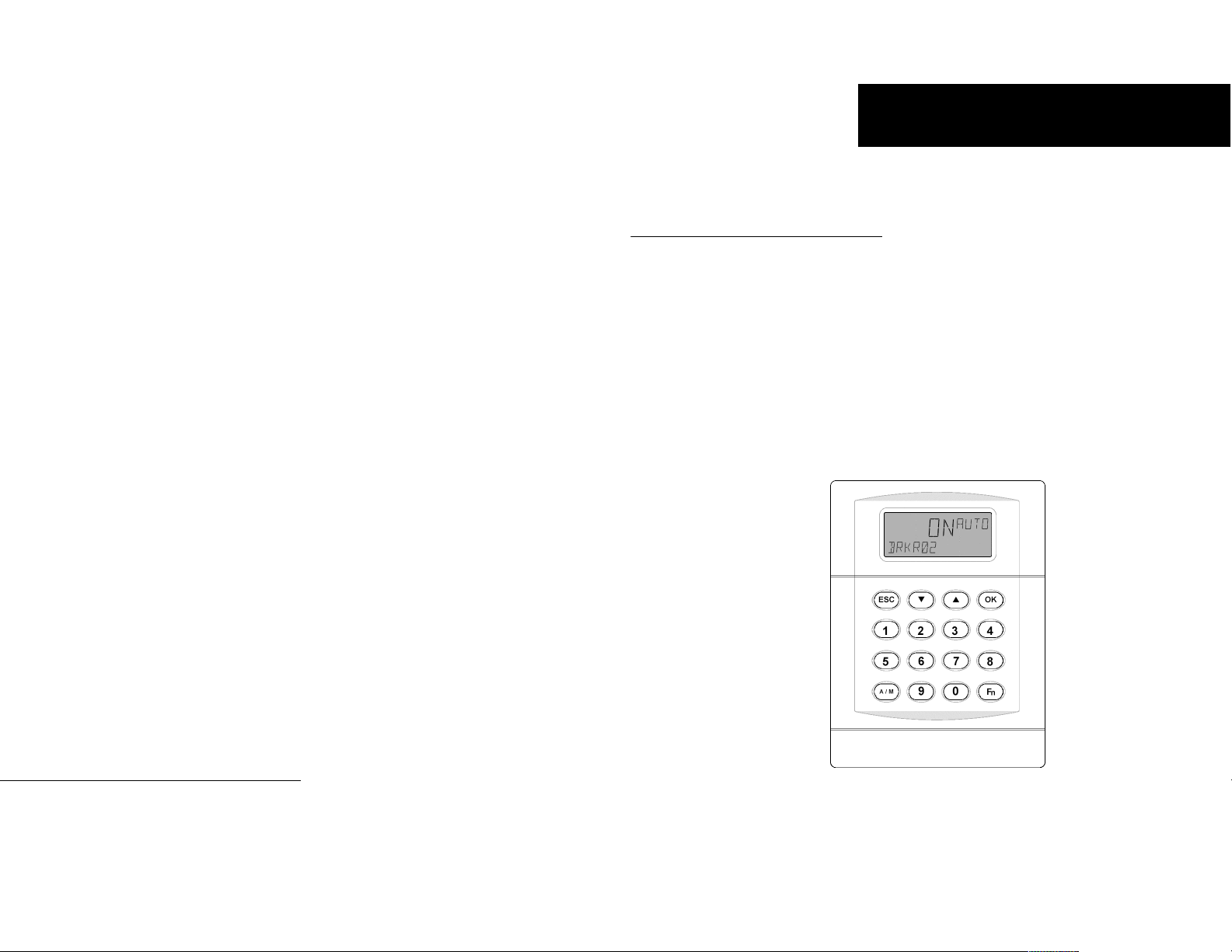
A Series® Lighting Controller
Handheld Programmer
Catalog No. ASRGLCHPK
g
DEH41088 R01
g
General Electric Company
41 Woodford Ave., Plainville, CT 06062
DEH41088 R01 0804 © 2004 General Electric Company
GE Consumer & Industrial
Page 2

Application....................................................................................................4
Menu Structure ............................................................................................4
Menu Descriptions.......................................................................................4
Schedules .............................................................................................................................................. 4
Calendar ............................................................................................................................................... 4
I/O Menu ............................................................................................................................................. 4
Lighting Group.................................................................................................................................... 4
Dimming Menu................................................................................................................................... 4
Burn Hours Menu............................................................................................................................... 4
Breaker Override Menu ..................................................................................................................... 4
Configuration Menu........................................................................................................................... 4
Event Menu .......................................................................................................................................... 3
Set Password. This function sets the
password for the current user.
Reset MSP430. This function resets the
back plane of the controller. Note that
this item should only be used for instant
remapping of the breaker or for
diagnostic purposes.
Reconfig Net. This function
reconfigures the controller’s address
using DNA. This is done when the
controller is first connected to the
network; since it is a subnet device, it
inherits the address of the master above.
For example, if the master address is 100
and the address of the subnet is 1,
Reconfig Net sets the address to 101.
Reset Device. This function performs a
hardware reset of the controller.
Save Flash. This function saves the
changes made to flash memory so they
can be reloaded if the battery goes dead
or to return to the previous version.
Load Flash. This function loads the
database with the last version saved to
flash memory. It overwrites the current
contents of the database and performs a
hardware reset.
Event Display
Alarm ALARM
Alarm Acknowledged ALARM ACK
Dead Battery DEAD BATT
Dead Battery
Restored
Command Failure CMD FAIL
Command Fail
Restored
Status ON STATUS ON
Status OFF STATUS OFF
Under Voltage UNDER VOLT
Under Voltage
Restored
Reset DEV RESET
Time / Date change TIME CHG
DB Load DB LOAD
DB Save DB SAVE
DB Clear DB CLEAR
Lnk Online DEV ONLINE
Lnk Offline DEV OFFLINE
Breaker Trip BREAKER TRIP
Breaker Trip
Restored
No events occurred NONE
DEAD BATT
RESTORED
CMD FAIL
RESTORED
UNDER VOLT
RESTORED
BREAKER TRIP
RESTORED
Table 1. Events captured in the CE Log.
Event Menu
These menu items are used to
acknowledge alarms, view battery status,
view or reset the CE Log, and set up the
CE Log. The CE log captures the events
listed in Table 1.
7
Page 3

Lighting Group
These menu items are used to view or
edit Zn 1–16 groups and to turn them
on or off manually.
Outputs. This function links breakers
and/or lighting groups to the group
output. It also assigns a specific switch
input (analog or digital) to each breaker
or group.
Schedule. This function turns the group
on and off according to a set schedule.
Astro. This function links Astro time to
turn the group on and off.
Photocell. This function turns the group
on and off with analog or digital inputs.
Override. This function overrides the
group from off to on for a set time.
Groups. This function turns the group
on or off when all nested groups turn on
or off, following OR logic.
Dimming Menu
These menu items are used to view
and/or edit the dimming modules that
can be optionally attached to the
product (Linknet devices 6 and 7) to
control the lighting ballast. The input to
these modules is a photocell (AI) and
the output is the analog output (AV).
Dim Mod 600 Submenu. These functions
adjust each control loop for dimming
module 1 with Linknet device 6. There
are eight control loops on a board and
each consists of the following functions:
• Ltg Lvl (input) – the input from
the photocell
• Ltg SP – the set light level
• Ltg OP
• Ltg PB (controller PB) – the
proportional gain of the feedback
loop
• Ltg RR (controller rest rate) – the
integral gain of the feedback loop
and the
Dim Mod 700 Submenu. These functions
are the same as Dim Mod 600 but for
Linknet device 7.
Burn Hours Menu
This function is used to view and/or
reset the breaker burn/run hours for an
individual breaker.
Breaker Override Menu
This function views the Override BV for
each breaker. Override is used to turn an
individual breaker on for a set time and
then shut it off. It is used for integration
but not by default.
Configuration Menu
These menu items are used to configure
the lighting controller and system.
Set Time. This function sets the time
and date of the controller.
Device Information. This function
provides information about the device,
such as the device name, model number,
firmware version build, and software
version.
Device Menu. This function sets up the
location and daylight savings time.
Application
This is the quick start guide for the
Handheld Programmer (cat. no.
ASRGLCHPK) for the A Series
Lighting Controller.
®
Menu Structure
The Handheld Programmer has two
modes of operation, depending on the
permission level of the user. Figure 1
shows the sequence of menus for displayonly mode and Figure 2 shows the
sequence for full-editing mode. The
default password in display-only mode is
1234 and in full-editing mode is 4129.
Menu Descriptions
Following are brief descriptions of the
menu items and the functions they
provide.
Schedules
This function views or edits Zn 1–16
schedules and turns them on or off
manually. Up to eight turn on/off times
can be scheduled per day for each day of
the week and two calendar references.
Calendar
This function views or edits the
Calendar reference, which is used to
select days of the year. Calendar is
referenced in the schedule object and
when the controller date matches the
calendar date, the schedule follows the
calendar on and off times.
I/O Menu
These menu items view and/or edit the
inputs and outputs.
Odd Breakers. The odd breakers are
those numbered 1, 3, 5, …, 65. These
functions provide the following:
• Commissioning
• Manually turning on or off
• Linking override inputs
• Assigning override times
• Enabling event logging for breaker
on, breaker off, tripped breaker,
and command failure
• Direct/reverse feedback setting
• Enabling flick warning
• Setting the time of flick warning
• Determining the status of the odd
breakers
Even Breakers. The even breakers are
those numbered 2, 4, …, 66. These
functions provide the same operations
as those of Odd Breakers.
Lighting Switches. This function is used
to manually turn the switches on or off
and to commission them.
Analog Input. This function finds the
value/status of the three analog inputs
on the controller and to commission
them.
Breaker Test. This function tests the
breakers for a set time.
6 3
Page 4

Schedules 1–16
Lighting Grps 1–16
Same as DIM
Brkr BrnHrs 1–66
Brkr Ovrd 1–66
Figure 1. Menu structure of lighting controller, display-only mode.
Odd Brkrs 01–65
Ltg Grps 1–16
Brkr Ovrd 1–66
Even Brkrs 02–66
BO 1–66
Ltg Grps 1–16
Brkr BrnHrs 1–66
SCH 1–66
MI101–512
BV2001–2066
Ltg Switches 101–502
Same as DIM 600
Analog IP
01–03
AI 1–3, 601–608,
701–708
MI101–512
BV2001–2066
Figure 2. Menu structure of lighting controller, editor mode.
Adjust Brkr Test
MI101–512
BV2001–2066
On/Off
Ltg Grps 1–16
4 5
 Loading...