

Page 1
DEH41083 Installation Guide Rev. 1
g
g
A Series® Lighting Control Panelboards
Remote Switch Expansion Module
Catalo
No. ASRGLCDSK
Page 2

Table of Contents
Application .......................................................................................................................... 3
Introduction ........................................................................................................................ 3
Three-Wire Connection ...................................................................................................... 3
Operation............................................................................................................................................................................. 3
Momentary Inputs .............................................................................................................................................................. 3
Maintained Inputs .............................................................................................................................................................. 3
Two-Wire Connection ........................................................................................................ 4
Operation .................................................................................................................................................................................... 4
Momentary Inputs...................................................................................................................................................................... 4
Maintained Inputs...................................................................................................................................................................... 4
Viewing and Editing Switch Status.................................................................................. 4
Checking Switch Status ...................................................................................................................................................... 4
Controlling Objects with a Switch – Case 1 .................................................................................................................... 5
Controlling Objects with a Switch – Case 2 .................................................................................................................... 5
Controlling Objects with a Switch – Case 3 .................................................................................................................... 6
Controlling Objects with a Switch – Case 4 .................................................................................................................... 6
Controlling Objects with a Switch – Case 5 .................................................................................................................... 7
Page 3
Application
This installation guide applies to the Lighting Controller
expansion module (cat. no. ASRGLCDSK), as illustrated
on the cover.
Introduction
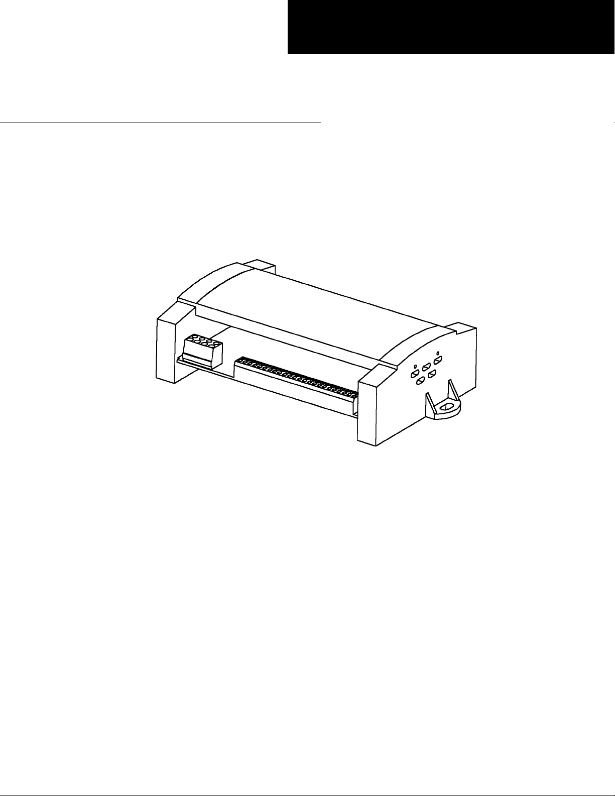
The A Series® Lighting Controller accepts 16 switch
inputs from the standard module, shown in Figure 1.
Standard Module
Inputs
Figure 2. Three-wire input connections.
Operation
The input voltage is converted to the corresponding
digital value listed in Table 1. If a connection is
made between all three of the input pins (shorting
ON, COM, and OFF) the controller goes to OFF state.
Power
Figure 1. A Series lighting controller with standard input module.
The standard module is mounted on the controller and
draws power from it. Additionally, the lighting controller
can also accept remote switch inputs from the remote
input expansion module, which has 16 switch inputs.
These modules are referred to as standard and remote in
this guide.
The remote module needs a separate 24 Vac/dc supply to
power it. NET2 on the controller board is connected to
the communication port of the remote module.
These modules use the LINKnet communications
protocol. Up to 12 LINKnet devices can be connected to
one controller. These modules handle inputs exclusively.
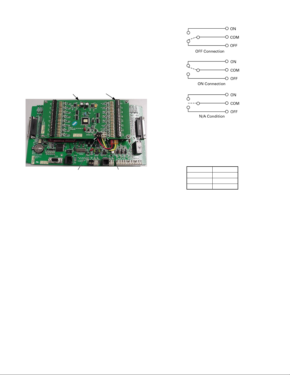
There are three pins per input labeled
These modules are designed to convert three analog input
values to the digital values 0, 2048, and 4096.
Communication
ON, COM, and OFF.
Three-Wire Connection
The three-wire connection states are shown in Figure 3.
Input, V Output
00
2.5 2048
5.0 4096
Table 1. Analog-to-digital conversion of voltages.
Momentary Inputs
The following rules apply to momentary inputs:
• All-state changing pulses must be sustained for 100
milliseconds or more.
• A multistate (MI) object must be used to determine
the input states.
• When the MI object transitions to
N/A condition, the corresponding BV object toggles.
MI 101 corresponding to BV 101, MI102
corresponding to BV102, and so on.
ON from OFF or
Maintained Inputs
A multistate (MI) object can capture maintained input
states. The multistate input (MI) object requires a
multistate input configuration (MIC) object to define
which input values determine a state change.
3
Page 4

Two-Wire Connection
The two-wire connections states are shown in Figure 3.
Object
Name
LTG SW
101–116
LTG SW
201–216
LTG SW
301–316
LTG SW
401–416
LTG SW
501–502
LINKnet
Object
Type
MI101–
MI116
MI201–
MI216
MI301–
MI316
MI401–
MI416
MI501–
MI502
Table 2. Switch object types and addresses.
Device
Address
1 Standard
2 Remote
3 Remote
4 Remote
5 Remote
Expansion
Module
Comment
Default
address
Settable by
dip switch
Settable by
dip switch
Settable by
dip switch
Settable by
dip switch
Figure 3. Two-wire input connections.
Operation
A two-wire connection requires a jumper between ON and
COM, which results in a default value of ON. If the switch
(AB) is open the state is
OFF.
ON and if it is closed the state is
Momentary Inputs
The following rules apply to momentary inputs:
• All state-changing pulses must be sustained for 100
milliseconds or more.
• A multistate (MI) object must be used to determine
which of the two states the input is in.
• This input configuration can generate two valid and
distinct states using digital values 0 and 4096,
representing 0 V and 5 V. A transition from
ON state of the MI object toggles the corresponding
OFF to
BV object. For example, changing the MI115 object
OFF to ON toggles the BV115 object.
from
Maintained Inputs
A multistate object (MI) can be used to capture the ON
and OFF states.
Checking Switch Status
To check switch status, first log on to the LCD
programmer, then use the up and down arrow keys to
scroll to the I/O menu:
Press the OK key to display the following menu:
Press the down arrow key twice to reach the lighting
switches menu:
Viewing and Editing Switch
Status
The handheld LCD Programmer, cat. no. GLCHPK, can
be used to view and manually edit switch status. See
DEH41088, LCD Programmer Quick Start Guide, for a
description of the operation and menu sequence.
The available switches are listed in Table 2.
Press OK to display the following menu:
The human figure indicates that the switch is not
commissioned. It does not matter whether the switch is
commissioned or not.
This display indicates that lighting switch 101 is off. Press
the up and down arrow keys to view the status of all other
available switches, as listed in Table 2.
4
Page 5

To put the switch in manual mode, press the OK key. The
word AUTO in the display will begin to flash.
Flashing
Press the A/M key to change the display to the following:
The arrow keys can be used to change the switch to the
ON, OFF, or N/A conditions.
Controlling Objects with a Switch – Case 1
To set a switch to control a particular object, first use the
arrow keys to the I/O menu, then press
odd breakers menu, as illustrated in the previous example.
If an odd-numbered breaker is desired, press
otherwise use the down arrow to display the even breakers
menu and then press
OK. A screen similar to the following
appears:
OK to display the
OK;
Press the down arrow key to display the following:
Flashing
Press OK and 2001 will begin flashing.
Flashing
To select the object for the switch to control, enter the
appropriate number with the numeric keypad, then press
OK. For instance, to link MI switch 116 (lighting switch
116 in Table 2), enter
1 - 1 - 6 - OK. The following display
appears:
Object Number
(flashing)
Object Type
Object Name
Controlling Objects with a Switch – Case 2
Use the arrow keys to scroll to the lighting group menu:
Press OK to start AUTO flashing, then press Fn, then press
OK two more times. This displays the Override screen:
Press OK for the following display:
Press the OK key; BV will start flashing:
Flashing
Press OK for the following display:
Press OK for lighting group 1 or press the arrow keys to
scroll to a different group. For example to access lighting
group 2, press the down arrow to get to the display
The cross symbol indicates that the group is in fault mode,
which we will ignore for this discussion. Press
OK and the
word AUTO begins flashing:
5
Page 6

Press the Fn key to display the outputs screen:
Press OK for the breaker 1 output display:
Flashing
Controlling Objects with a Switch – Case 3
Go to the Schedule submenu of the Lighting Group menu
by pressing the down arrow key from the Outputs
submenu (see Case 2).:
Press OK; the following screen may appear:
Press OK again for the following display:
Press the down arrow key to see that nothing is attached to
this BO:
Press OK; the following display may appear:
Press the up and down arrow keys until the MI object
appears:
Flashing
Flashing
Press OK again and the flashing will change as follows:
Flashing
Use the numeric keys to change MI to any number given
in Table 2. For instance, if 112 is entered, the display
appears as
Flashing
Press OK to connect MI 112 to the group.
Press OK again; the 1 will start flashing:
Flashing
Use the numeric keys to change the switch number to any
of those in Table 2. Press
OK when the desired number
appears; this switch is now attached to BO1 and can be
used to control it.
Controlling Objects with a Switch – Case 4
From the Schedule submenu, press the down arrow twice
to reach the Photocell submenu:
Press OK; the following screen may appear:
6
Page 7

Flashing
Press OK, then the up arrow key twice to reach the
following display:
Flashing
Press OK to change the flashing characters as follows:
Flashing
Use numeric keys to change the number from 1 to any
desired number, as listed in Table 2. Press
OK, to link the
MI switch to the group through the photocell input.
Controlling Objects with a Switch – Case 5
From the photocell submenu, as in Case 4, press the down
arrow key to reach the Override submenu:
Press OK to change the flashing characters as follows:
Flashing
Use numeric keys to change MI to any value listed in
Table 2. Press
OK to link the MI switch to the Group object
by override input.
Press OK; the following screen may appear:
Press OK to display the following screen:
Use the arrow keys to change the BI display to MI:
Flashing
7
Page 8

g
GE Consumer & Industrial
General Electric Company
41 Woodford Ave., Plainville, CT 06062
DEH41083 R01 0804 © 2004 General Electric Company
 Loading...