

Page 1

DEH41085 Installation Guide Rev. 1
g
g
A Series® Lighting Control Panelboards
Daylight Optimization Module
Catalo
No. ASRGLCDOK
Page 2
Introduction
This manual provides basic overview and setup
information for the Daylight Optimization Module. It
includes an overview of the Daylight Optimization Module
board and a typical setup.
The Daylight Optimization Module is designed to take
advantage of natural sunlight and other ambient light to
conserve power delivered to indoor lights. Once a setpoint
light value has been established for a given bank of lights,
the Daylight Optimization Module maintains that amount
of light in the area. The Daylight Optimization Module
uses sunlight harvesting; it measures the amount of light
in an area with a photodiode and adjusts the dimming
ballast to maintain the desired amount of light in the
area.
LINKnet
Address DIP
Switch
Power and
Comm
Connections
Photocell
Inputs
Dimming Ballast
Control Outputs
Input
Sensitivity
Potentiometers
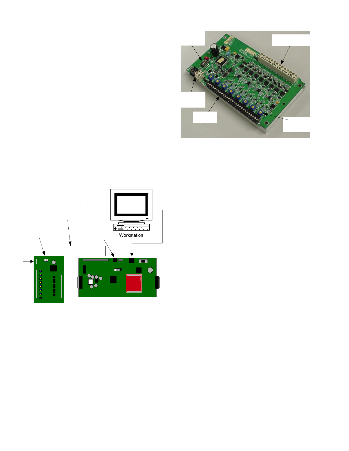
Network Configuration
The Daylight Optimization Module is a subnet device of
the Lighting Controller LINKnet device. Communication
is via the connection from NET1 on the Daylight
Optimization Module to NET2 on the Lighting
Controller, as illustrated in Figure 1.
LINKnet
Daylight
Optimization
Module
Figure 1. Lighting Controller and Daylight Optimization Module configuration.
Lighting
Controller
Ethernet
Specifications
The dimming module has the following hardware
features, as illustrated in Figure 2:
• Selectable DIP switch for the LINKnet address
• Power and communications connections
• Eight photocell inputs
• Eight input sensitivity potentiometers
• Eight 1 V to 10 V, <0.5 mA dimming ballast
control outputs
Figure 2. Daylight Optimization Module circuit board layout.
Power
The Daylight Optimization Module is a half-wave rectified
device that requires a 15 VA, 24 Vac Class 2 transformer.
Using a transformer to power a Daylight Optimization
Module device and a full-wave rectified device could cause
serious electrical damage. A single transformer should
only power multiples of the same device type, without
exceeding the VA rating of the transformer. When
multiple devices share a transformer, always ensure a
GND-to-GND connection for all devices connected to the
transformer.
Communication
The Daylight Optimization Module communicates with
the lighting Controller over an RS-485 subnetwork
connection. A maximum of eight RS-485 subnet devices
can be connected to one Lighting Controller. For correct
operation, each subnet expansion module requires a
unique address. To wire an RS-485 connection, use 18gauge twisted-pair wire, which will support
communication lengths of up to 4000 ft.
Addressing
Each subnet device requires a different address from any
other expansion module connected to a given Lighting
Controller. The valid range of addresses is 1–12, with 1
reserved as the address of the standard input expansion
module and 12 as the address of the Handheld
Programmer. The factory default address for the Daylight
Optimization Module is 6. In the default database,
dimming is set up for addresses 6 and 7. It is highly
recommended that only address 6 or 7 be used for a
Daylight Optimization Module.
Inputs
The Daylight Optimization Module has eight photocell
inputs, connected as illustrated in Figure 3. Each input
has four pins: two supply power (PWR and GND), one for
the input (IP#), and the last for signal adjustment (ADJ).
Page 3

The inputs on the Daylight Optimization Module are
designed specifically for GE indoor photodiodes, catalog
number RPESN-IN.
Outputs – Analog variable objects (AV625 to AV632 and
AV725 to AV732) are read-only objects that display the
voltage delivered to the dimming ballasts.
The ranges of objects for the first and second Daylight
Optimization Module connected to a Lighting Controller
are listed in Table 1 and Table 2. Object offsets for the
dimming circuit are listed in Table 3.
Figure 3. Input and output connections to the Daylight Optimization Module.
Outputs
The Daylight Optimization Module has eight 1 V to 10 V
outputs, connected as illustrated in Figure 3 to dimming
ballasts drawing less than 0.5 mA. Each Daylight
Optimization Module output channel can sink up to 25
mA of current, supporting up to 50 dimming ballasts. A
single Daylight Optimization Module can control up to
400 ballasts.
Daylight Optimization Module Configuration
Each input to the Daylight Optimization Module controls
a corresponding output in a proportional-integral (PI)
feedback loop. The eight inputs (IP1 to IP8) and eight
outputs (OP1 to OP8) comprise the eight feedback loops
on the Module.
The eight sensitivity potentiometers on the Daylight
Optimization Module (indicated in Figure 2) are used to
calibrate the gain of the photodiode connection to the
given input channel.
Operation
This section describes the operation of the Daylight
Optimization Module.
Mapping the Inputs
The Daylight Optimization Module has two types of
objects, analog input (AI) and analog variable (AV). This
section describes how to map the functional objects from
the master device (Lighting Controller) database to the
Module.
Inputs (AI601 to AI608 and AI701 to AI708) – The analog
input objects are read-only and gather voltage values from
a photodiode input.
Setpoint Variables (AV601 to AV608 and AV701 to AV708) –
These variables define the desired amount of light for the
feedback channel. The setpoint value can be edited with
the Handheld Programmer.
Proportional Band (AV609 to AV616 and AV709 to AV716)
and Reset Rate (AV617 to AV624 and AV717 to AV724)
Variables – These variables control the proportional and
integral properties of the individual proportional-integral
(PI) feedback loops. These values should be treated as
read-only unless you have detailed knowledge of (PI)
feedback systems.
BACnet
Description Type
Lighting Levels [0–100] RO AI601–608 Fn 4, 117–124
Lighting SP (set point)
[0–100]
Lighting Proportional
Band [0–200?]
Lighting Reset Rate
(internal usage)
Lighting Output (8
outputs)
Table 1. Object ranges for the first Daylight Optimization Module.
Description Type
Lighting Levels [0–100] RO AI701–708 Fn 4, 133–140
Lighting SP (set point)
[0–100]
Lighting Proportional
Band [0–200?]
Lighting Reset Rate
(internal usage)
Lighting Output (8
outputs)
Table 2. Object ranges for the second Daylight Optimization Module.
SetpointAVProportional
Loop # Input #
1 1 1 9 17 25
22 2 10 1826
33 3 11 1927
44 4 12 2028
55 5 13 2129
66 6 14 2230
77 7 15 2331
88 8 16 2432
Table 3. Object offsets for the Daylight Optimization Module dimming circuit.
RW AV601–608 —
RO AV609–616 —
RO AV617–624 —
RO AV625–632 —
RW AV701–708 —
RO AV709–716 —
RO AV717–724 —
RO AV725–732 —
Object
BACnet
Object
Band AV
Reset
Rate AV
Modbus
Register
Modbus
Register
Output
AV
Example – For Daylight Optimization Module 1 addressed
as 6, the objects related to control circuit 1 are as listed in
Table 4.
SetpointAVProportional
Loop # Input #
2 AI602 AV602 AV610 AV618 AV626
Table 4. Control circuit objects for example.
Band AV
Reset
Rate AV
Output
AV
Page 4

Typical Object Values
Following are descriptions of the five objects related to
each feedback loop:
Analog Input (AI) – Used to collect analog-to-digital values
from the photodiode input. Manually entering values into
this object has no effect on the PI feedback loop.
Setpoint Analog Variable (AV) – Used to set the desired
amount of light in a given area.
Proportional Band Analog Variable (AV) – The value given to
the proportional component for the PI feedback loop.
Incorrect values for this object could cause the output to
oscillate. This value is set to 100 in the default database.
Reset Rate Analog Variable (AV) – The value given to the
integral component for the PI feedback loop. Incorrect
values for this object could cause the output to oscillate.
This value is set to 5 in the default database.
Output Analog Variable (AV) – The voltage sent to the
output. Manually entering values into this object has no
effect on the PI feedback loop.
g
GE Consumer & Industrial
General Electric Company
41 Woodford Ave., Plainville, CT 06062
DEH41085 R01 0804 © 2004 General Electric Company
 Loading...