

Page 1

imagination at work
GE Energy
™
Arc Vault
Installation, Operation, Maintenance
Protection System
Page 2

Arc Vault™ Protection System DEH-41483 Rev. 3
© 2011 General Electric All Rights Reserved
Page 3
DEH-41483 Rev. 3 Arc Vault™ Protection System
HAZARD CATEGORIES
The following important highlighted information appears
throughout this document to warn of potential hazards or
to call attention to information that clarifies a procedure.
Carefully read all instructions and become familiar with
the devices before trying to install, operate, service or
maintain this equipment.
DANGER
Indicates a hazardous situation which, if not avoided, will
result in death or serious injury.
WARNING
Indicates a hazardous situation which, if not avoided,
could result in death or serious injury.
CAUTION
Indicates that if the hazard is not avoided could result in
minor or moderate injury.
TRADEMARKS
Arc Vault™ Protection System
WARRANTY
This document is based on information available at the
time of its publication. While efforts have been made to
ensure accuracy, the information contained herein does
not cover all details or variations in hardware and
software, nor does it provide for every possible
contingency in connection with installation, operation,
and maintenance. Features may be described herein that
are not present in all hardware and software systems. GE
Industrial Solutions assumes no obligation of notice to
holders of this document with respect to changes
subsequently made. GE Industrial Solutions makes no
representation or warranty, expressed, implied, or
statutory, with respect to, and assumes no responsibility
for the accuracy, completeness, sufficiency, or usefulness
of the information contained herein. No warrantees of
merchantability or fitness for purpose shall apply.
Contact your local sales office if further information is
required concerning any aspect of Arc Vault™ operation
or maintenance.
Contact your local sales office if further information is
required concerning any aspect of Arc Vault™ operation
or maintenance.
NOTICE
Is used to notify of practices not related to personal
injury.
© 2011 General Electric All Rights Reserved iii
Page 4

Arc Vault™ Protection System DEH-41483 Rev. 3
Table of Contents
iv © 2011 General Electric All Rights Reserved
Page 5

DEH-41483 Rev. 3 Arc Vault™ Protection System
Table of Contents
TABLE OF CONTENTS
SECTION 1. Introduction.........................................................................................................................................................................................................1
General Information ....................................................................................................................................................................................................................1
Related publications....................................................................................................................................................................................................................1
SECTION 2. Receiving, Handling and Storage..............................................................................................................................................................2
Receiving...........................................................................................................................................................................................................................................2
Equipment packages.................................................................................................................................................2
Inspecting for Damage ..............................................................................................................................................2
Filing a Claim.............................................................................................................................................................2
Handling............................................................................................................................................................................................................................................2
Lifting.........................................................................................................................................................................2
Rollers .......................................................................................................................................................................3
Forklifts......................................................................................................................................................................3
Jacks .........................................................................................................................................................................5
Storage...............................................................................................................................................................................................................................................5
Switchgear.................................................................................................................................................................5
SECTION 3. Description...........................................................................................................................................................................................................7
General...............................................................................................................................................................................................................................................7
Summary Description.................................................................................................................................................................................................................7
Compartment Areas....................................................................................................................................................................................................................8
Arc Vault compartment .............................................................................................................................................................................................................8
Feeder Cable Compartment....................................................................................................................................13
Cable lugs - mechanical type..................................................................................................................................13
Ground Bus ...................................................................................................................................................................................................................................13
SECTION 4. Equipment Installation ................................................................................................................................................................................15
General............................................................................................................................................................................................................................................15
Site Location............................................................................................................................................................15
Foundation Requirements.......................................................................................................................................15
Foundation Preparation...........................................................................................................................................15
Assembly and Installation of Switchgear Equipment...............................................................................................................................................17
General Requirements............................................................................................................................................17
Detailed Assembly and Installation Instructions (indoor) ........................................................................................17
Anchoring Switchgear Equipment Indoors.................................................................................................................................................................... 20
Anchoring By Anchor Bolts......................................................................................................................................20
Anchoring By Weld..................................................................................................................................................20
Control Wire Connections .......................................................................................................................................21
Power Cable Connections.......................................................................................................................................21
Relays and Control Devices....................................................................................................................................22
SECTION 5. Installing and Removing The Arc Vault Device................................................................................................................................23
General............................................................................................................................................................................................................................................23
Inspection and Preparation of Arc Vault..................................................................................................................23
Arc Vault Installation................................................................................................................................................23
Rejection Feature....................................................................................................................................................23
© 2011 General Electric All Rights Reserved v
Page 6

Arc Vault™ Protection System DEH-41483 Rev. 3
Table of Contents
Installing Arc Vault Device .....................................................................................................................................................................................................23
Pre-Installation precautions .................................................................................................................................... 23
Installation Procedures ........................................................................................................................................... 23
SECTION 6. Testing and inspection................................................................................................................................................................................25
General............................................................................................................................................................................................................................................25
Key Interlocks ..............................................................................................................................................................................................................................25
Test......................................................................................................................................................................... 25
Arc Vault Relay............................................................................................................................................................................................................................26
Final Steps to Be Taken Before Energizing Equipment.............................................................................................................................................26
SECTION 7. Operation...........................................................................................................................................................................................................27
Arc Vault device Operation....................................................................................................................................................................................................27
Arc Vault Drawout Operation...............................................................................................................................................................................................27
Arc Vault Positions..................................................................................................................................................27
Drawout Operation..................................................................................................................................................27
Front Doors ...................................................................................................................................................................................................................................27
Operation ................................................................................................................................................................ 27
Door Removal......................................................................................................................................................... 27
Door Installation...................................................................................................................................................... 28
Arc Vault Equipment Accessories.......................................................................................................................................................................................28
Arc Vault Key Interlock............................................................................................................................................ 28
Key Interlock Operation Check............................................................................................................................... 28
Padlocking the Cassette Racking Door.................................................................................................................. 29
Padlocking the Arc Vault Cassette ......................................................................................................................... 29
Padlocking the Shutter............................................................................................................................................29
Removing Shutter Units (on a de-engergized cubicle)........................................................................................... 30
Installing a Shutter Unit (in a de-energized cubicle)............................................................................................... 30
SECTION 8. Initial Test and Activation...........................................................................................................................................................................31
Making Arc Vault Ready to Test..........................................................................................................................................................................................31
Device Test Procedure.............................................................................................................................................................................................................32
Arc Vault Relay Controller Setup.........................................................................................................................................................................................33
Verify Primary Circuit Current and Voltage...................................................................................................................................................................33
Arc Vault System Activation Procedure ..........................................................................................................................................................................33
SECTION 9. Energizing the Switchgear.........................................................................................................................................................................34
Before energizing.......................................................................................................................................................................................................................34
Uninterruptable Power Supply................................................................................................................................ 34
Potential Transformer Fuse Block FB1.............................................................................................................................................................................34
Energizing Procedures.............................................................................................................................................................................................................34
SECTION 10. Post Event Procedure...................................................................................................................................................................................35
SECTION 11. Maintaining the Switchgear......................................................................................................................................................................36
Maintenance Requirements..................................................................................................................................................................................................36
Device and Instrument Compartments...........................................................................................................................................................................36
Maintenance of Arc Vault Device .......................................................................................................................................................................................36
Arc Vault Device: Test for Proper Operation .......................................................................................................... 36
Checks After Switchgear Is De-energized.............................................................................................................. 36
vi © 2011 General Electric All Rights Reserved
Page 7

DEH-41483 Rev. 3 Arc Vault™ Protection System
Table of Contents
Lubrication...............................................................................................................................................................36
Instruments, Instrument Transformers, and Relays................................................................................................37
Arc Vault Compartment Interiors ............................................................................................................................37
Bus Area .........................................................................................................................................................................................................................................37
Cable Compartment.................................................................................................................................................................................................................37
Overall equipment.....................................................................................................................................................................................................................38
Paint Refinishing.........................................................................................................................................................................................................................38
Arc Vault Lifting Mechanism pt # GAVLD1..................................................................................................................................................................... 38
SECTION 12. Troubleshooting .............................................................................................................................................................................................39
APPENDIX A. Torque Values..................................................................................................................................................................................................40
© 2011 General Electric All Rights Reserved vii
Page 8

Arc Vault™ Protection System DEH-41483 Rev. 3
Table of Contents
viii © 2011 General Electric All Rights Reserved
Page 9

DEH-41483 Rev. 3 Arc Vault™ Protection System
Introduction
SECTION 1. INTRODUCTION
GENERAL INFORMATION
This manual contains procedures for receiving, handling,
storage, equipment installation, operation, and
maintenance and service of Low Voltage Switchgear with
Arc Vault™ Protection System.
• Summary of switchgear equipment which is a list of
all the components furnished with the switchgear,
including the breakers, identified by catalog
number.
These are all the documents necessary to install, operate,
and maintain the equipment. One complete set of
drawings and instruction books is shipped with the
equipment.
NOTICE
The personnel responsible for installing, operating,
and servicing this equipment should be thoroughly
familiar with the contents of this manual.
Before any installation work is performed, thoroughly
read and understand the material in this instruction
manual and the drawings furnished with the equipment.
The documentation shipped with the equipment includes
the Summary, Front View, Elementary Diagram,
Connection Diagram and Instruction Book. This material
is located in a forward compartment tagged
"INSTRUCTIONS IN THIS COMPARTMENT." The
documentation provides all of the information necessary
for installation of the switchgear. When requesting
information from the General Electric Company, include
the complete data appearing on the equipment
nameplate, requisition number, summary number, and
elementary diagram number. The nameplate is located in
the lower left, front corner of the lineup.
When requesting information concerning any specific
item furnished with the switchgear, refer to that item by
description, part number, its location within this manual,
and any applicable drawing number. Any material
external to the equipment, which may be required to
meet local codes (such as mats, screens, railings, etc.), is
not furnished by the General Electric Company.
If there are any questions or requirements not covered in
this manual or in the accompanying drawings, please
contact the local sales office of the General Electric
Company.
RELATED PUBLICATIONS
In addition to instruction books, the following drawings
will be supplied as required for each order of Arc Vault
equipment:
• General arrangement drawings, including front view
and floor plan.
• Elementary and connection drawings (or wiring
routing tables) which indicate and identify test and
connection points including terminal blocks, device
studs, switch contact developments, and remote
connections.
© 2011 General Electric All Rights Reserved 1
Page 10
Arc Vault™ Protection System DEH-41483 Rev. 3
Receiving, Handling and Storage
SECTION 2. RECEIVING, HANDLING AND
STORAGE
RECEIVING
Equipment packages
Every package leaving the factory is plainly marked with
the case number, requisition number, and customer's
order number. If the equipment has been split for
shipment, the section numbers of the equipment
enclosed in each shipping package are identified.
NOTICE
To avoid the loss of any parts when unpacking, the
contents of each container should be carefully
checked against the packing list before discarding the
packing material.
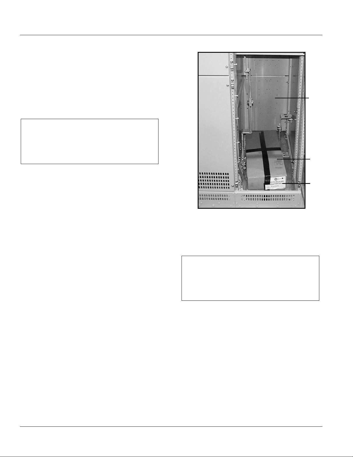
The contents of each shipping package are listed on the
Master Packing List. In addition, this list includes the
number of the shipping crate in which miscellaneous
parts needed to install and operate the equipment (such
as hardware, contact lubricant, touch-up paint, breaker
closing devices, etc.) are located. Normally, such devices
are packed in a cardboard carton and the carton secured
in an empty switchgear compartment. See Figure 2-1. If
such items are packed in a switchgear section instead of
a separate crate, the list will indicate the appropriate
section number in which they are stored.
Figure 2-1 Packaging of loose material for shipment
1
2
3
1-Spare compartment
2-Carton containing loose material
3-Shipping label listing contents of carton
Inspecting for Damage
All equipment leaving the factory is carefully inspected
and packed by personnel experienced in the proper
handling and packing of electrical equipment. Upon
receipt of any equipment, immediately perform a visual
inspection to ascertain if any damage has been
sustained in shipping or if there are any loose parts.
Circuit breakers and Arc Vaults may be shipped
separately in individual containers with the breaker in the
open position. Circuit breakers and Arc Vaults should be
unpacked and visually inspected for damage or loose
parts as soon as possible after they have been received.
Be sure to inspect all devices mounted or packed inside
compartments of each section to see if any have been
dislodged or damaged.
Filing a Claim
If any damage is evident, or indication of rough handling
is visible, file a claim for damage at once with the
transportation company and notify the nearest General
Electric Company Sales Office immediately. Information
on damaged parts, part number, case number,
requisition number, etc., should accompany the claim.
HANDLING
NOTICE
It is preferable to leave the shipping skids in place
under the switchgear until it reaches its final location.
The equipment should be installed in its final location
prior to installing the circuit breakers.
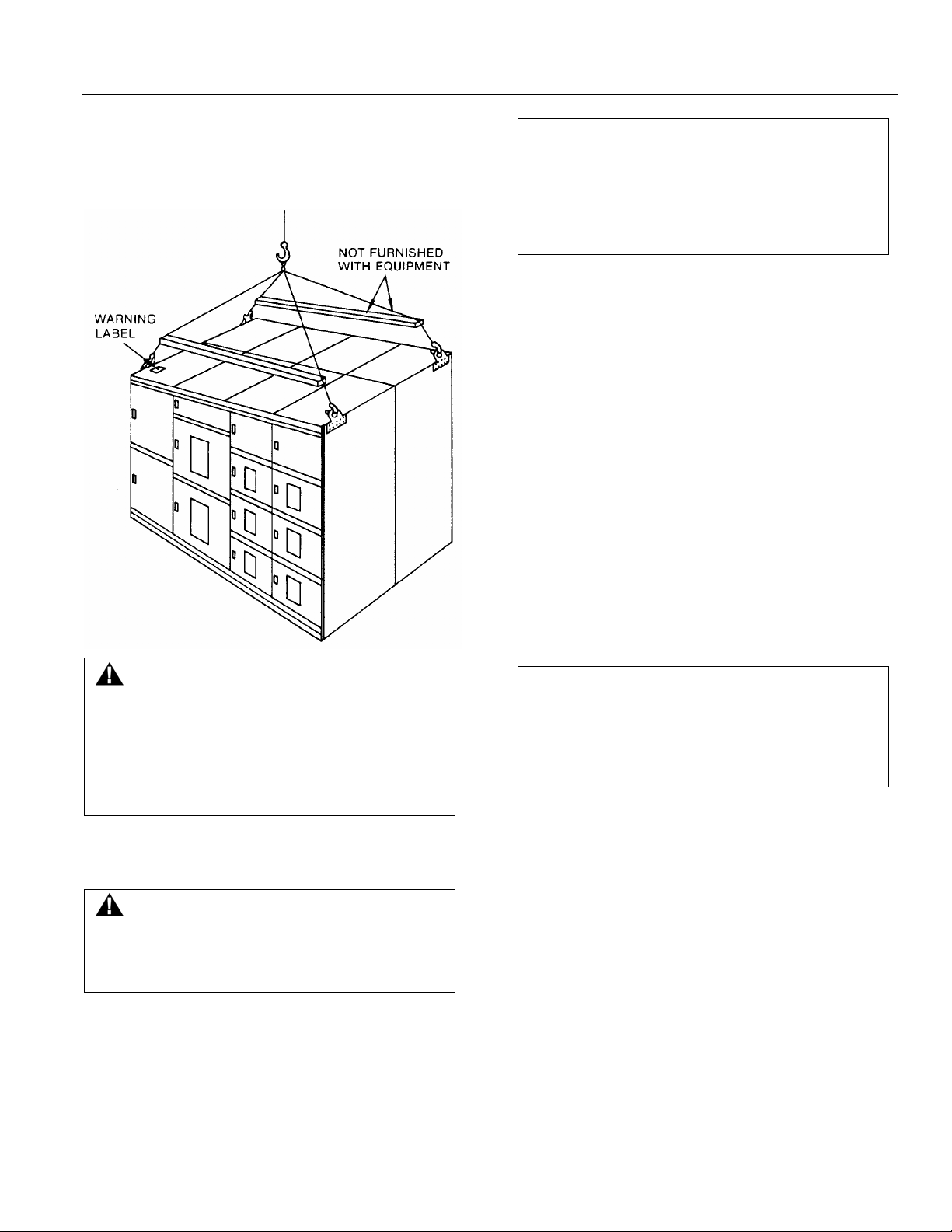
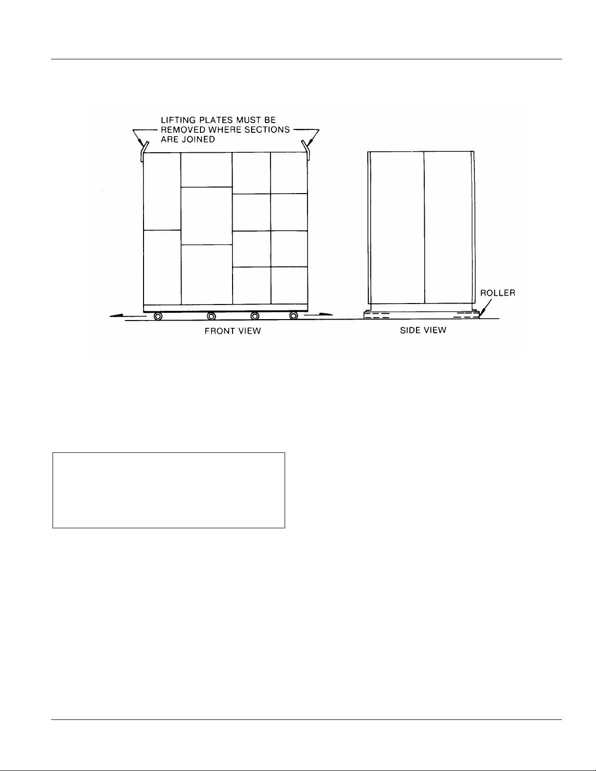
Lifting
The indoor switchgear sections are best handled by lifting
with a crane as shown in Figure 2-2. Removable lifting
plates are provided, as standard equipment, on the top of
each switchgear section. To preserve the external
appearance of the equipment, it is suggested that the
lifting plates be left in place except where adjacent
equipments must be bolted together, i.e. shipping splits,
etc.
Utilize four equal length cables and an overhead crane,
each with a minimum load rating of twice the weight of
the Switchgear. Estimated weights for shipping splits
appear on the Front View drawings.
2 © 2011 General Electric All Rights Reserved
Page 11
DEH-41483 Rev. 3 Arc Vault™ Protection System
Receiving, Handling and Storage
Example: Switchgear Section Weight = 2,000 pounds. The
crane and the four lift cables must have a minimum load
lifting capacity of 4,000 pounds.
Figure 2-2 Recommended lifting method
CAUTION
Gently lower the switchgear section onto the level site
location. If the switchgear is roughly handled or
jarred, it is possible to damage or misalign internal
components.
Rollers
If crane facilities are not available, the equipment may be
moved into position by means of construction rollers
placed under the shipping skids. The switchgear may be
raised enough for the placement of rollers by means of a
fork lift or jack.
There should never be less than four rollers under the
equipment unless the line-up is less than five feet long.
Use one roller for each 18 inches of equipment length.
Forklifts
WARNING
The angle between the cables and the top of the
equipment must be at least 45 degrees. If this is not
possible because of lack of headspace, spreader bars
must be used. Also, lift cables with greater load
capability may be necessary, depending upon the
angle between the cables and the crane hook.
Connect a cable from the crane to the four lifting plates
located on the top-front and rear of the indoor
switchgear. See Figure 2-2.
WARNING
Do not stand under switchgear while it is being
moved. Serious injury may occur if the cables or
lifting device fail.
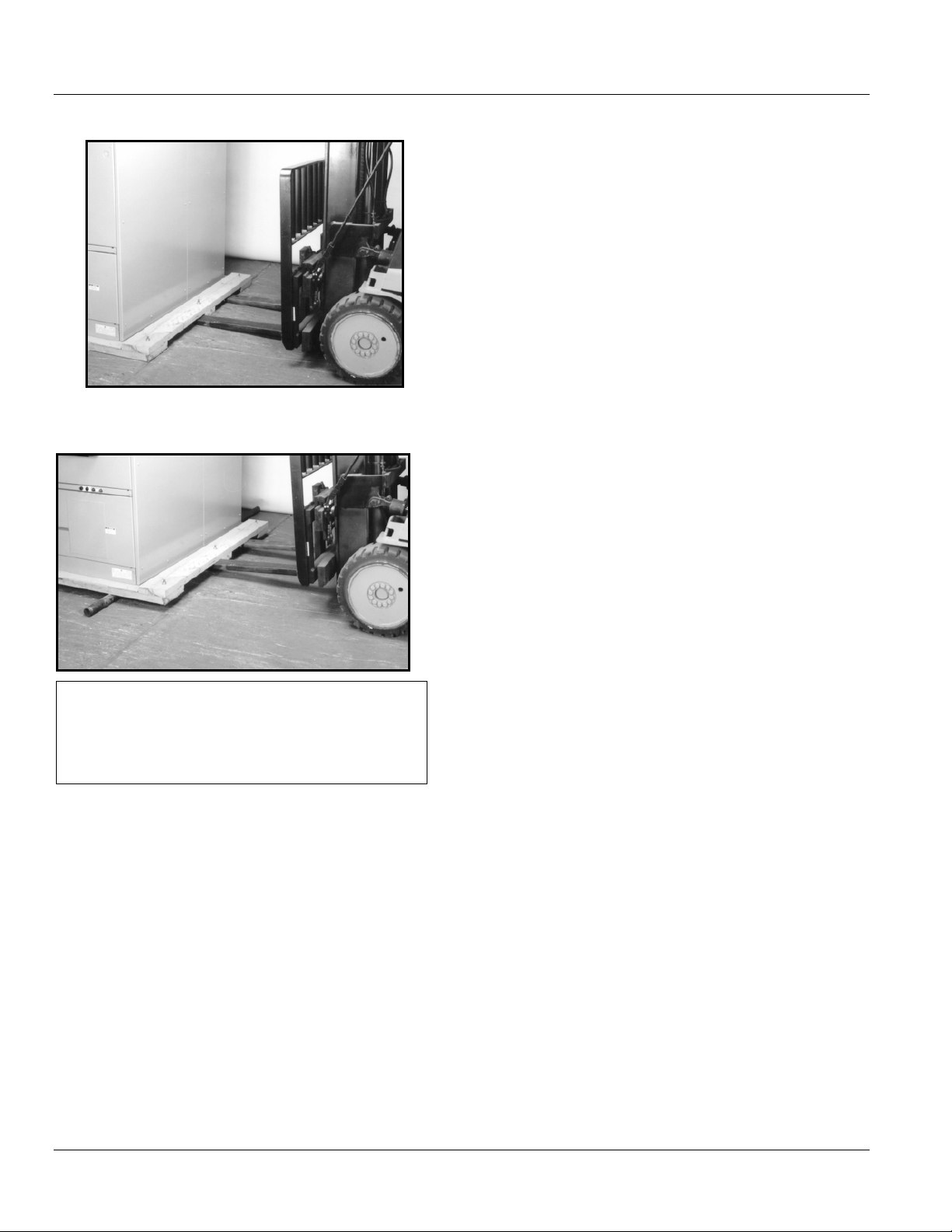
When using a forklift to raise the line-up to position rollers
underneath, proceed as follows:
1. Expand forklift tines to their maximum (widest)
extension.
2. Carefully insert tines of forklift below one side of the
switchgear line-up at the approximate center of the
panel as shown in Figure 2-3.
NOTICE
Do not attempt to lift or move the equipment with a
forklift positioned in the front or rear of the
equipment. Equipment may tip over and get
damaged.
1. Raise equipment and position one roller under the
skids close to the raised end of the line-up.
2. Carefully lower the gear until it rests on the roller as
shown in Figure 2-4.
3. Repeat the lifting process at the other end and place
the appropriate number of rollers under the skids
spacing them evenly across the width of the line-up.
© 2011 General Electric All Rights Reserved 3
Page 12
Arc Vault™ Protection System DEH-41483 Rev. 3
Receiving, Handling and Storage
Figure 2-3 Placing forklift tines under shipping skid
Figure 2-4 Placement of rollers under shipping skid
NOTICE
If shipping skids are removed prior to final placement
of equipment, rollers may only be used to move the
equipment in a direction parallel to the front.
4. While carefully pushing the switchgear to its final site
position, the rollers that are freed from the rear of the
switchgear are then repositioned at the forward end.
This procedure should be continued until the
switchgear is in its final location. See Fig. 2-8.
5. When the switchgear is in its final position, remove all
lug bolts holding the shipping skids to the switchgear
line-up.
6. Insert the tines of the forklift at one end of the line-
up, raise slightly, and remove the loose rollers.
7. Lower the end of the gear carefully to the floor.
8. Raise the other end of the line-up slightly and
remove the remaining roller at that end.
4 © 2011 General Electric All Rights Reserved
Page 13
DEH-41483 Rev. 3 Arc Vault™ Protection System
Receiving, Handling and Storage
Figure 2-5 Method of rolling equipment into place
Jacks
Jacks may be used in place of forklifts to raise and lower
switchgear. Jacks
1. Place a jack under the front and rear corners of one
end of the line-up.
CAUTION
Do not place jacks in any other location other than
the front and rear corners of the switchgear. Doing so
may result in serious damage to the switchgear
equipment.
2. Raise the switchgear evenly and just enough to
position a roller beneath the equipment. Gently lower
the switchgear onto the roller. Repeat the procedure
at the opposite end of the switchgear, raising the
gear far enough to place the appropriate number of
rollers under the skids, spacing then evenly across
the width of the line up. Gently lower the gear onto
the rollers.
4. When the switchgear is in its final position, remove all
lag bolts holding the shipping skids to the switchgear
line-up.
5. Place one jack at each corner, front and rear, of the
switchgear. Carefully raise the line-up evenly and
remove the rollers and the shipping skids. Evenly
lower the line-up to the floor and remove the jacks.
STORAGE
Switchgear
If it is necessary to store the switchgear equipment for
any length of time, the following precautions should be
taken to prevent corrosion or deterioration.
1. Remove protective covering. Check thoroughly for
damage.
2. Store in a clean, dry, rodent-free location with
moderate temperature and provide protective
coverings to prevent dirt, water, or other foreign
substances from entering the switchgear.
3. While carefully pushing the switchgear to its final site
position, the rollers that are freed from the rear of the
switchgear are then repositioned at the forward end.
This procedure should be continued until the
switchgear is in its final location.
© 2011 General Electric All Rights Reserved 5
Page 14

Arc Vault™ Protection System DEH-41483 Rev. 3
Receiving, Handling and Storage
CAUTION
Remove all cartons, containers and any other
miscellaneous packaging and packing material from
inside the switchgear sections before energizing any
internal heaters. To prevent fire, remove any plastic or
polyethylene shrouding from the switchgear sections
before energizing any internal heaters.
3. If dampness or condensation may be encountered in
the storage location, heaters must be placed inside
the switchgear sections to prevent moisture damage.
Approximately 250 watts of heat in each section is
required. On outdoor switchgear equipment, this
may be accomplished by making a temporary power
supply connection to the heaters already installed in
the equipment.
CAUTION
If the space heaters are to be temporarily energized
from external source, it is important to remove the
fuses on the secondary side of the control power
transformer. This precaution is to prevent a feed back
of higher voltage to other portions of the equipment
through the CPT primary.
6 © 2011 General Electric All Rights Reserved
Page 15
DEH-41483 Rev. 3 Arc Vault™ Protection System
Description
SECTION 3. DESCRIPTION
GENERAL
This section contains a description of the General Electric
Arc Vault™ Low Voltage gear. It also describes the
functions of the electrical and mechanical systems of Arc
Vault.
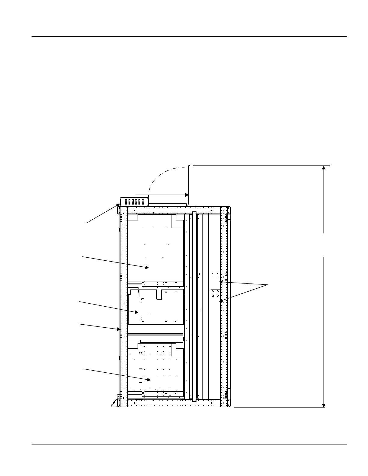
Figure 3-1 is a side view of a typical Arc Vault section
showing compartmentation.
Figure 3-1 Side view of Arc Vault Stack
Refer to Figure 4-3 on page 17 for cable entry space dimensions and location.
Ceiling height above exhaust door must be min. 12 feet. Exception to this requirement is above cable entry space. Sprinkler
heads cannot be located within a five foot radius of the perimeter of the Arc Vault stack.
SUMMARY DESCRIPTION
General Electric Arc Vault Protection System is a free
standing assembly of metal-enclosed sections containing
cable termination provisions, auxiliary power circuit
protective devices, controls, and instrumentation.
INTERSECTIONAL
CONTROL WIRING
TROUGH
ELECTRONICS
COMPARTMENT
ARC VAULT
DEVICE
COMPARTMENT
COMPARTMENT
DOORS
Exhaust Door requires
clearance from
conduit, Plumbing
and other mechanical
devices.
Open Exhaust Door
Height is 94.1 inch
CABLE CONNECT
BUS
BOTTOM
ELECTRONICS
COMPARTMENT
INCLUDING UPS
© 2011 General Electric All Rights Reserved 7
Page 16
Arc Vault™ Protection System DEH-41483 Rev. 3
Description
COMPARTMENT AREAS
The front enclosure of each section is divided into three
individual compartments. These compartments house
controls component, the Arc Vault™ device and the
optional Uninterruptable Power Supply compartment.
ARC VAULT COMPARTMENT
A standard Arc Vault compartment, Figure 3-2, is located
below the controls compartment.
Routine wiring inspections and fuse checks or fuse
replacements can be performed with the Arc Vault
compartment door in the closed position so that operators
are protected from the energized primary circuits.
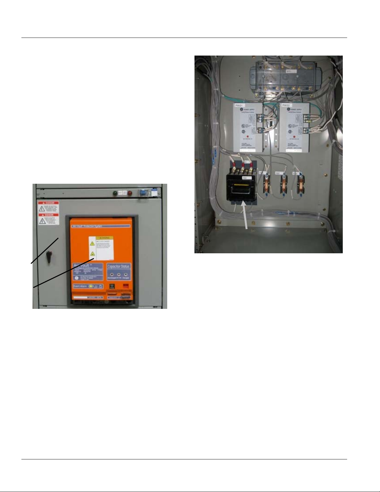
Figure 3-2 Arc Vault compartment
Figure 3-3 Arc Vault controls compartment
1
2
1. Compartment door
2. Arc Vault device
An Arc Vault controls compartment, Figure 3-3, is available
as a standard feature. Internal hinged panels are used to
mount instruments and other devices associated with the
Arc Vault monitoring and control.
Relays and similar devices may be installed in the
compartment behind the swing-out device panel.
Potential transformer
fuse block FB1
The Arc Vault compartment is a closed-door drawout
compartment. Figure 3-4 and Figure 3-5 shows standard
construction. The Arc Vault compartment doors remain
closed and latched while the Arc Vault is racked out from
the CONNECTED position, through TEST, to the
DISCONNECTED position.
Arc Vault compartment doors do not have any ventilation
slots, thus protecting operators from hot ionized gases
which may be vented by the Arc Vault during circuit
interruption. Additionally, the Arc Vault compartment is
enclosed by grounded steel barriers on the top, sides,
bottom, and front. In the back, a flame-retardant, track
resistant, glass-filled polyester base minimizes the
possibility of fault communication between compartments
to the bus.
8 © 2011 General Electric All Rights Reserved
Page 17

DEH-41483 Rev. 3 Arc Vault™ Protection System
1
Description
Figure 3-4 Arc Vault compartment
4
3
1. Access port to racking mechanism
2. Racking access door screw
3. Arc Vault position indicator
4. Arc Vault device escutcheon
2
© 2011 General Electric All Rights Reserved 9
Page 18

Arc Vault™ Protection System DEH-41483 Rev. 3
Description
Figure 3-5 Arc Vault compartments showing drawout rails
3
4
5
2
6
1
1
1. Drawout rails
2. Cassette bottom and racking box
3. Secondary disconnects
4. Cassette side barrier
5. Primary disconnects (covered by shutter)
6. Racking arm
Primary disconnect shutters, Figure 3-6 ,are available as
options to provide protection against contact with the
energized stationary primary disconnects when the device
is removed from its compartment. The shutters are
constructed from glass-reinforced polyester insulating
material.
Referring to Figure 3-6, the shutters (movable barriers)
prevent frontal access to the primary disconnect line
stationary disconnects.
10 © 2011 General Electric All Rights Reserved
Page 19

DEH-41483 Rev. 3 Arc Vault™ Protection System
Description
Figure 3-6 Arc Vault primary disconnect shutters in closed position
1
2
3
4
1. Cassette Walls
2. Shutters (retractable barrier)
3. Shutter Operating lever
4. Racking mechanism insertion port
The shutters are closed when the Arc Vault is in the
DISCONNECT Position. As the Arc Vault is racked from the
DISCONNECT Position to the TEST Position the shutters
remain fully closed. As the device is racked from the TEST
Position to the CONNECTED Position, the shutters open
allowing the device to connect to the primary disconnects.
The cassette racking arm slots engage fixed racking
anchor pins on the sides of the Arc Vault. As the racking
arms are rotated by operation of the racking crank, the Arc
Vault is pulled into the compartment, and locked in its final
connected position.
Note that extra items shown in Figure 3-6, (such as
secondary disconnects and shutters) are optional and may
appear in any compartment or not be included at all,
depending on the equipment specified.
Figure 3-7 Arc Vault Device front view
© 2011 General Electric All Rights Reserved 11
Page 20

Arc Vault™ Protection System DEH-41483 Rev. 3
Description
Figure 3-8 Frame 2 Arc Vault (rear view)
Primary disconnects
The Arc Vault compartment has four positions as described in the following chart.
Device Position in
the cassette
Primary
Disconnects
Secondary
Disconnects
Arc Vault Functionality
Arc Vault can be operated electrically.
CONNECTED Engaged Engaged
Ready to transfer arc
Arc Vault device ready to test.
TEST Disengaged Engaged
Control circuits operations can be tested and
verified. Plasma gun can be discharged
DISCONNECTED Disengaged Disengaged
WITHDRAWN Disengaged Disengaged
Locked out during transition, Safe for
maintenance when fully disconnected.
Arc Vault can be removed from the
compartment. Safe for maintenance.
Arc Vault door
position
Closed
Closed
Closed
Open
12 © 2011 General Electric All Rights Reserved
Page 21

DEH-41483 Rev. 3 Arc Vault™ Protection System
Description
Figure 3-9 Racking handle for movement of Arc Vault
1
1. Arc Vault device position indicator
Movement of the Arc Vault between the CONNECTED, TEST,
and DISCONNECTED positions is performed by the use of a
racking handle, see Figure 3-9, which engages the racking
mechanism mounted on the cassette. An optional remote
racking device is also available. Movement to the
WITHDRAWN position is manually performed after opening
the compartment door. These positions are illustrated and
described more fully in SECTION 5 .
WARNING
The door should NOT be opened when the Arc Vault is
charged and in the CONNECTED position. Although
the device compartment door may be opened in any
position, it is recommended that the door only be
opened when the Arc Vault is in the DISCONNECTED
or WITHDRAWN position.
Cable lugs - mechanical type
When furnished, the terminal boards, for such connections
are located in an enclosed vertical wiring trough mounted
on the side of the cable compartment. The trough is of steel
construction with bolted covers to provide an isolation
barrier between the control wiring and the adjacent power
cables.
GROUND BUS
Figure 3-10 Cable termination provisions
On a 480V nominal system the Arc Vault Protection System
can be applied on systems with available current up to
65KA.
Feeder Cable Compartment
The rear cable and terminal compartment, Figure 3-10,
provides for cable installation and terminations. The cable
bending space meets the requirements of the National
Electric Code. Various arrangements of single or double
cable terminals are provided, depending upon the
purchaser's requirements.
When specified, racks for the support of feeder cables are
located in the cable compartment. The actual support of
the cables is provided by lashing them to these racks.
Also located in the cable compartments are provisions for
terminating control wires between external devices and
control circuits within the switchgear equipment.
© 2011 General Electric All Rights Reserved 13
All General Electric AKD-20 switchgear sections are
grounded to the internal equipment ground bus (4), Figure
3-11, located at the bottom of the cable compartment.
Page 22

Arc Vault™ Protection System DEH-41483 Rev. 3
Description
Figure 3-11 AKD-20 Cable termination compartment
1
2
3
4
1. Feeder runbacks
2. Vertical riser bus covers
3. Horizontal main bus
4. Ground bus (behind steel cover)
14 © 2011 General Electric All Rights Reserved
Page 23

DEH-41483 Rev. 3 Arc Vault™ Protection System
Equipment Installation
SECTION 4. EQUIPMENT INSTALLATION
GENERAL
This chapter contains complete instructions for installing
General Electric Arc Vault Low-voltage equipment.
CAUTION
Personnel installing this equipment must be familiar
with this instruction manual and all articles of the
National Electrical Code applicable to the installation
of this switchgear. In addition, all drawings, both
mechanical installation and electrical, must be
understood and strictly followed to prevent damage
to the switchgear or equipment being protected by
the switchgear.
Foundation Requirements
For optimum performance of your General Electric
switchgear equipment, the foundation requirements
expressed in this chapter should be strictly adhered to.
NOTICE
The foundation for the outdoor switchgear must
provide proper drainage of ground and surface water
accumulations away from the equipment.
The foundation must be strong enough to prevent
sagging due to the weight of the switchgear structure
and to withstand the shock stress caused by the
opening of the breakers under fault conditions. The
shock loading is approximately 1.5 times the static
load.
NOTICE
Before installation work is started, it is important to
review all of the drawings provided, including the
General Electric equipment arrangement drawings,
site installation drawings, elementary and remote
connection drawings, mechanical connection
drawings, and the summary of equipment list.
All expendable hardware for shipping purposes only,
is painted yellow or tagged with yellow adhesive tape
and may be discarded at completion of the
installation phase.
Site Location
In general, the location of the switchgear equipment will
have been predetermined during the specification and/or
procurement of equipment phases. Indoor locations within
buildings impose certain requirements which must be met
so that the switchgear may operate efficiently with a
minimum of maintenance.
In locating the Arc Vault equipment, adequate aisle space
must be provided at the front and rear of the equipment to
ensure proper ventilation of and to allow service and
maintenance with the front and rear doors open. The
recommended aisle space is shown on the floor plan
supplied with the equipment drawings.
The switchgear equipment should be placed in an area
where clean, dry air is free to circulate around and above it.
Since air is taken into the equipment at the bottom of each
section and exhausted at the top, a location with good
airflow must be provided for efficient operation. A minimum
of 30 inches of clear space above the equipment is
recommended.
© 2011 General Electric All Rights Reserved 15
The foundation must be flat and level in all planes. Refer to
Figure 4-1 for definition of flat and level.
Figure 4-1 Definition of flat and level
Plumb line
Perpendicular
Plane#1
Plane#2
Foundation Preparation
Refer to Figure 4-2 along with the owner's foundation
construction drawings, and the General Electric
supplemental installation drawings. Although the indoor
switchgear equipment can be mounted directly on a
smooth, level floor, it is recommended that recessed steel
channels be installed for supporting the equipment. Anchor
bolts and channels are to be provided by the purchaser.
Surface of pad
on both axes
to within 0.25"
over 10' span
.062"
NOTICE
When the equipment is installed on a surface subject
to impact (shock) loads due to operating conditions or
environmental seismic (earthquake) conditions, the
anchor bolts should be fabricated of medium carbon
steel (grade 5 load rating).
The floor channels under the front and rear switchgear
anchor points (see Figure 4-2) should be embedded in a
level concrete slab with their top surfaces flush with the
finished floor. It is essential that these steel channels be
level and aligned with each other prior to final anchoring, to
Page 24

Arc Vault™ Protection System DEH-41483 Rev. 3
Equipment Installation
prevent distortion of the switchgear structure, to assure
proper mechanical and electrical connections between
shipping splits, and to assure proper interfacing to other
close-coupled equipment.
Arc Vault section, Switchgear and Load Center Substations
are frequently mounted on steel floors and/or structural
steel in industrial installations (such as a mezzanine) to
minimize usage of production floor space. Regardless of the
If studs or anchor bolts are to be used, they should be
installed in the foundation as it is poured. It is important
that the studs or bolts are spaced to agree with dimensions
given on the General Electric job drawings. The dimensions
between anchor bolts for a particular installation are
dependent upon the configuration of equipment ordered.
The dimensions shown on Figure 4-2 cover all of the
standard enclosures available for Arc Vault equipment.
type of mounting surface, the requirements for a smooth
level surface remain.
Figure 4-2 Location of equipment anchor points
16 (22 section)
16 (22 section)
46.5
All units are in inches
If studs or anchor bolts are to be used, they should be
installed in the foundation as it is poured. Space the studs
or bolts to agree with dimensions given on the General
Electric job drawings. The dimensions between anchor bolts
for a particular installation are dependent upon the
configuration of equipment ordered. The dimensions shown
on Figure 4-2 cover the standard enclosure available for Arc
Vault equipment.
Figure 4-3 illustrates the space available for conduit and/or
cable entrance through the bottom or top of each
equipment section. The space required for control wiring
entry to the optional wiring trough is also shown.
16 © 2011 General Electric All Rights Reserved
Page 25

DEH-41483 Rev. 3 Arc Vault™ Protection System
Equipment Installation
Figure 4-3 Floor plan and cable entry space
ASSEMBLY AND INSTALLATION OF SWITCHGEAR
EQUIPMENT
General Requirements
Before assembling or installing the switchgear equipment,
all components should be available at the site location. This
will facilitate switchgear component identification as well
as installation. The foundation should be prepared in
accordance with the instructions in SECTION 4 Equipment
Installation, and all embedded conduits installed and
capped.
NOTICE
If rollers are to be used for movement of the
equipment to its permanent installation, it is
recommended that the shipping skid not be removed
until the equipment is placed in position over the
anchor bolts.
If a transformer is not part of the installation, and/or the
equipment has been split for shipment, place the center
section on the foundation first. Assemble the remaining
sections outward from the center section, in each direction.
first in accordance with the instructions furnished with the
transformer. All remaining sections of the switchgear
should then be installed.
NOTICE
Before assembling and installing the switchgear
equipment, the foundation must be absolutely level
and clear of debris to prevent damage and possible
mis-operation of the switchgear equipment.
Detailed Assembly and Installation Instructions (indoor)
The recommended procedure for installation of an indoor
switchgear or Load Center Unit Substation is as follows:
1. POSITION THE EQUIPMENT-Position the equipment or
sections of the complete equipment in their final location.
If the switchgear equipment is part of a Load Center Unit
Substation, the transformer section should be set on its pad
© 2011 General Electric All Rights Reserved 17
Page 26

Arc Vault™ Protection System DEH-41483 Rev. 3
Equipment Installation
Figure 4-4 Lifting plate location
Lifting Plate
NOTICE
If the lifting plates must be reassembled on the
equipment for lifting, they must be moved to
locations where unused screw holes are available,
generally by shifting the plate horizontally on the
mounting surface one bolt-hole from its previous
location. When remounting the lifting plates, torque
the mounting bolts to 7-9 ft-lbs.
NOTICE
NOTICE
If the equipment line-up was split into shipping
sections, the lifting plates on corners of adjacent
sections shown in Figure 4-4 must be removed.
Failure to remove these plates will interfere with
mating adjacent sections and prevent installation of
bus splice plates, structure tie plates, etc.
Arc Vault sections are equipped with lifting plates. These
plates can be left in place when the Arc Vault section is
positioned separate from the line up. Lifting plates must be
removed if section will be positioned directly next to the
switchgear line up.
Once the lifting plates have been removed, they may be
discarded.
All mating sections of the equipment line-up
(including transformer, if applicable) must be securely
fastened together prior to tightening anchor bolts
fastening the equipment to the mounting surface.
2. REMOVE THE SHIPPING SKIDS-The equipment is fastened
to the shipping skids with 3/8-3 lag screws through the
equipment anchoring holes. See Figure 4-6.
Equipment shipping sections up to 10 feet long will be
fastened to the skids with four lag screws, one in each
corner. The shipping skid and lag screws are expendable
material and may be disposed of at the purchaser's
discretion.
3. FASTEN SECTIONS TOGETHER-After placement of the
equipment and installing the anchor bolts loosely, the
various shipping sections must be rigidly fastened together.
Through-bolts fasten each section of the switchgear
equipment to the adjacent section. Figure 4-5 shows the
location of the through-bolts.
18 © 2011 General Electric All Rights Reserved
Page 27

DEH-41483 Rev. 3 Arc Vault™ Protection System
Equipment Installation
Figure 4-5 Location of through-bolts
Figure 4-6 Equipment attachment to shipping skids
After completing the installation of the main bus splice bars,
the joint covers may be mounted and secured by a 3/8-16
nylon bolt and polyester flat washer if the bus insulation
option has been supplied with the equipment.
4. INTERCONNECT CONTROL WIRING - Interconnection of
control wiring across shipping splits is accomplished by
connecting to terminal blocks located in the cross-section
wiring trough on top of the equipment.
© 2011 General Electric All Rights Reserved 19
Page 28

Arc Vault™ Protection System DEH-41483 Rev. 3
Equipment Installation
If terminal blocks are provided, each wire must be attached
to the correct point on the terminal block, following the
circuit identification number attached to each wire.
ANCHORING SWITCHGEAR EQUIPMENT INDOORS
Correct anchoring of the switchgear equipment to the
foundation is very important. After completion of reassembly of the equipment at the shipping splits, the
equipment anchoring procedure should be completed.
Anchoring By Anchor Bolts
1. The front of the equipment is attached to the embedded
channel sills (1), Figure 4-7, by two 3/16-inch fillet welds (2).
It is recommended that two welds, each 2-1/2 inches long
(min.), be used for each section to firmly tie the bottom
width post (3) to the channel sill.
2. The rear of the equipment may be anchored by one of
three procedures:
• The first method is by plug welds (4), Figure 4-7, using
the anchor bolt holes in the rear sill angle (5). The plug
weld should receive a minimum 1/2-inch bead around
the entire circumference of the anchor bolt hole.
Indoor equipment is normally secured to its final mounting
surface by anchor bolts threaded into the embedded
channel sills. The bolts were loosely threaded into place
before reassembling the equipment shipping splits and
connecting to the close-coupled transformer, if appropriate.
The anchor bolts should now be tightened with a torque of
35-40 ft-lbs.
Anchoring By Weld
An alternate method of anchoring the equipment to its
foundation is to weld the equipment to floor sills (or the
floor itself if constructed of steel). Several methods, shown
on Figure 4-7, are available to the purchaser for welding the
equipment to the channel sills.
• A second method of securing the front and rear sill
angles (5) to the channel sill (1) is the use of two linear
fillet welds (2) for each section. It is recommended that
each weld be 2-1/2 inches long (min.) with a 3/16-inch
fillet (min.).
• A third method for anchoring the rear of the equipment
is to remove the rear sill angle (5) from the switchgear
and weld the rear bottom width post (6) to the channel
sill (1). These welds (2) should, like the front welds,
have a 3/16-inch (min.) fillet and each have a
minimum length of 2-1/2 inches.
20 © 2011 General Electric All Rights Reserved
Page 29

DEH-41483 Rev. 3 Arc Vault™ Protection System
Equipment Installation
Figure 4-7 Indoor equipment weld anchoring
1. Channel sill
2. 3/16-inch fillet weld
3. Front sill angle
4. Plug weld in anchor bolt hole
5. Rear sill angle
6. Rear width post
The four anchor bolts should be tightened with a torque of
45-55 ft-lbs.
CAUTION
If the equipment is to be subjected to operational or
environmental (seismic) shock loading, the factory
must be consulted for anchoring recommendations.
Control Wire Connections
For external control wiring, refer to Figure 4-3 for
switchgear cable area dimensions, and connect the control
wires to the switchgear section as follows.
1. When control conduits enter the switchgear from
below, they should not extend more than one inch
above the floor. The control wires may be pulled
through the conduits before or after the switchgear is
installed.
2. Route the control wires from the conduits through the
wiring trough at the side of the cable compartment,
shown in Figure 4-3. Connect the cables to the terminal
blocks in accordance with the connection diagrams for
the equipment.
3. If the control conduits enter from above, drill the top
cover within the available space indicated. See Figure
4-3. Control wires should be routed to the wiring trough
and connected to the terminal blocks as described
previously.
Power Cable Connections
Connect the main cables to the main lugs. Before any main
cable connections are made, the cables should be identified
to indicate their phase relationship with the equipment.
Adequate electrical and mechanical clearances must be
provided between conduit, cables, and bus.
© 2011 General Electric All Rights Reserved 21
Page 30

Arc Vault™ Protection System DEH-41483 Rev. 3
Equipment Installation
Where the cables enter the section, they can be lashed to
Figure 4-8 Typical cable lashing
optional cable supports at the rear of the cable
compartment as required.
Mechanical cable terminals are normally included with the
switchgear (compression terminals are supplied when
ordered) and are mounted at the ends of the breaker
runbacks in the cable compartment. Carefully follow the
cable manufacturer's recommendations for installation of
cable.
Nylon rope – 3/8
inch (9.5 mm)
diameter.
Minimum of 5
wraps
Install the cables in the proper path to the terminals, using
temporary lashing if required. Cut the cables to the proper
length. Strip the insulation to the desired dimension, being
careful not to damage any strands.
6 inches
(152 mm)
For copper cables, coat the wires with GE lubricating grease
D6A15A2, insert the cables into the terminals, and tighten
per torque values in Table A-2 in Appendix A.
For aluminum cables, wire brush the wire strands
thoroughly. Immediately after wire brushing, coat the cable
strands with a quality oxide inhibiting compound such as
Penetrox A. Insert exposed wires into the terminals and
tighten the set screws in accordance with values shown in
the torque Table A-2 in Appendix A.
CAUTION
The torque values shown in the table are for dry
threads only. Do not grease or otherwise lubricate the
threads on the cable terminals as this will permit
over-tightening of the screw and possible damage to
the terminal or cable.
The cable supports in Figure 4-8 can be optionally ordered
from the factory. The following instructions for cable
lashing should be used as a guide. Run and bend the main
cable in a most convenient orientation, making sure the
main cable has been located directly up against any cable
braces (if present) before it connects to the main cable
terminals.
Using a 3/8 inch diameter continuous nylon rope or
equivalent (minimum 2000 pounds tensile strength) at 6
inches from the main cable terminals, make five revolutions
around the "A" and "B" phase main cables, making sure the
rope does not overlap. Make five revolutions around the "B"
This should result in the oozing of compound material from
between individual strands. Wipe off any excess compound.
Bolt the cable terminal connectors to the ends of the bars in
the cable compartment. A non-oxidizing grease, such as GE
lubricating grease D6A15A2 furnished with each
equipment, should be used at these connection surfaces.
The bolts should be tightened in accordance with values
shown in the torque Table A-2 in Appendix A.
and "C" phase main cables. With the remaining rope, wrap
around the main cable lashing between the "B" and "C"
phase and the cable brace (if present) with a minimum of 5
revolutions getting as much revolutions as possible
between the phases. Continue wrapping between the "A"
and "B" phase around the main cable lashing and the cable
brace (if present) with a minimum of 5 revolutions getting as
much revolutions as possible between the phases. Securely
tie off the remaining rope. Repeat this lashing at every 6-
Lash the cables securely to the cable support, if present, to
inch interval.
take their weight off the runbacks and to brace them
against short circuit forces in the event of a fault.
Relays and Control Devices
Remove all blocking on relays and devices as shown in the
instructions accompanying the devices.
WARNING
Risk of shock. The equipment must be completely deenergized before installing or removing the arc fault
device. Failure to do so may result in death or serious
injury.
22 © 2011 General Electric All Rights Reserved
Page 31

DEH-41483 Rev. 3 Arc Vault™ Protection System
Installing and Removing The Arc Vault Device
SECTION 5. INSTALLING AND REMOVING THE
ARC VAULT DEVICE
GENERAL
Inspection and Preparation of Arc Vault
Before installing, operating, or removing an Arc Vault, check
thoroughly for damaged or loose parts and for any dirt or
foreign matter which may be on the Arc Vault. Be sure that
a thin film of GE lubricating grease D6A15A2 is present on
primary disconnects of the switchgear before installing the
Arc Vault.
Arc Vault Installation
To install an Arc Vault, proceed as follows:
1. Before installing check the contact areas on each
primary disconnect bar or cluster of fingers for foreign
matter that may have accumulated. Clean these areas
if necessary. Be sure that a thin film of GE lubricating
grease D6A15A2 covers the contact areas before
putting the Arc Vault in the compartment.
2. Check to see that the Arc Vault matches its respective
compartment. The Arc Vault is assigned a part or mark
number. This number is shown on the sheets of the
summary, the front view drawings, and on the
identification card on the Arc Vault shipping carton. The
Arc Vault may also be identified using the 6 digit
catalog number.
3. To locate the Arc Vault in the proper compartment,
refer to the breaker location list on the front view
drawing. Find the proper Arc Vault device by the
identification card on the carton.
Rejection Feature
Drawout breakers of the same type and rating are
interchangeable in their equipment compartments.
Arc Vault devices will be rejected in a standard AKD-20
switchgear compartment. Drawout breakers will be
rejected from a Arc Vault compartment.
INSTALLING ARC VAULT DEVICE
Pre-Installation precautions
Prior to lifting the Arc Vault to its intended compartment
location, observe the following precautions.
1. Check the compartment to ensure that it is free of
foreign objects.
2. Verify that the Arc Vault is the correct type for that
compartment.
3. Ensure that the Arc Vault is discharged.
4. Apply a thin fresh coat of GE lubricating grease
D6A15A2 to the breaker’s primary disconnects.
5. Ensure that the position indicator on the cassette is in
the disconnected position and is correctly positioned
for initial engagement. To do this, open the racking
handle door and insert the racking handle and rotate it
fully counterclockwise.
Installation Procedures
To install the Arc Vault, proceed as follows.
1. Carefully place the Arc Vault device in front of the
section in which it is to be installed.
2. Open the compartment door by rotating the door latch
assembly ¼ turn clockwise.
3. Using the Arc Vault lifting mechanism shown in Figure
11-1 page 38 (or a suitable lifting mechanism and the
appropriate lifting fixture), raise the device above the
elevation of the rails.
WARNING
Do not stand under the Arc Vault during the lifting
operation. This may result in injury if the device is not
positioned properly on rails.
4. Fully withdraw rails to stops.
5. Slowly lower and guide the device to allow the 4 Arc
Vault wheels to align with the rails. Remove the lifting
device. The device is now positioned on the draw-out
rails.
6. Roll the device into the compartment until the racking
forks meet the racking pin, this is the DISCONNECT
position. If an incorrect Arc Vault has been installed, the
interference pins on the Arc Vault will interfere with the
rejection pins in the compartment prior to reaching the
disconnect position. At this point, the racking forks on
the cassette are contacting the fixed racking pins on
the device.
7. Slide rails back into compartment. Close the
compartment door and rotate latch ¼ turn counterclockwise.
8. Engage the racking handle by using a slot screwdriver
to open the racking shaft door by rotating it clockwise,
then insert hex manual racking handle.
9. Rotate the handle clockwise as far as it will go. As you
rotate the handle clockwise, the device will travel from
the DISCONNECT, through the TEST.
10. See SECTION 1 for detailed procedure during racking to
start test procedure.
© 2011 General Electric All Rights Reserved 23
Page 32

Arc Vault™ Protection System DEH-41483 Rev. 3
Installing and Removing The Arc Vault Device
To remove the Arc Vault
1. Discharge the Arc Vault by pressing the Discharge
button.
2. Use a slot screwdriver the open the racking shaft door
by turning clockwise. Insert the racking handle and
rotate it counterclockwise until the Arc Vault travels
from CONNECT through TEST to the DISCONNECT
position, as shown by the position indicator. This
operation should be performed with the door closed.
3. Open the compartment door and fully extend the
drawout rails. Roll Arc Vault out to rail stops. This is the
WITHDRAWN position.
4. Attach the lifting device and raise Arc Vault off
drawout rails.
5. Push the drawout rails back into the compartment.
6. Pull the Arc Vault forward until the primary disconnects
clear the compartment.
7. Lower the Arc Vault onto a flat surface free of
protrusions that could damage internal parts.
Figure 5-1 Engage the racking screw with the racking
handle
1
3
1. Arc Vault drawout position indicator
2. Racking shaft access
3. Racking handle
2
24 © 2011 General Electric All Rights Reserved
Page 33

DEH-41483 Rev. 3 Arc Vault™ Protection System
Testing and inspection
SECTION 6. TESTING AND INSPECTION
Table 6-1 Switchgear test voltage
GENERAL
After the equipment has been installed and all connections
made, it must be tested and inspected before it is put in
service. Although the equipment and devices have been
tested at the factory, a final field test must be made to be
sure that the equipment has been properly installed and
that all connections are correct.
WARNING
Risk of shock. The equipment must be completely deenergized while the tests are in progress. Failure to do
so may result in death or serious injury.
Directions for testing relays, instruments, and meters are
given in the instruction book furnished for each device. The
proper settings of the protective relays and Arc Vault trip
units are normally determined from a complete power
system coordination study performed by the purchaser or
their consultant; therefore, the settings of these devices
must be made by the purchaser. When the equipment is
shipped from the factory, the time dial of all inverse-time
induction disc relays (i.e., IFC types) is set to zero to prevent
contact bounce during transportation.
Switchgear
Voltage Rating
600V
480V
KEY INTERLOCKS
After initial installation of the switchgear equipment, all
necessary interlock keys should be inserted into the
appropriate locks and all spare keys should be stored in a
location in accordance with the owner's established
procedures.
ANSI
Test Voltage,
AC RMS
2200V
1960V
Field
Test Voltage,
AC RMS
1650V
1470V
CAUTION
Refer to the key interlock schematic included in the
summary furnished with the equipment to determine
the sequence of operation and the correct number of
operating keys required. This precaution is necessary
since the improper use of spare keys will defeat the
interlocking scheme.
NOTICE
The trip setting adjustments of the relay for each Arc
Vault may be at any setting when shipped from the
factory and must be correctly set prior to energizing
the equipment.
General instructions for setting the relays are given in Arc
Vault Relay Controller page 33.
The extent of the tests on the equipment as a whole will
depend on the type and function of the equipment. Tests
which should be performed, however, include Arc Vault
operation, and switchgear meggering, phasing, and
grounding checks.
If local codes demand a high potential test, or the
purchaser wishes to make these tests, the voltage should
not exceed 75 percent of the IEEE factory test voltage.
For the power circuit, the IEEE factory test voltage is two
times switchgear rating plus 1,000 volts.
CAUTION
Potential and control power transformers must be
disconnected during high-voltage testing.
© 2011 General Electric All Rights Reserved 25
Test
The compartment housing the Arc Vault has a TEST position
in which the primary contacts are disconnected while the
secondary contacts are still engaged. This TEST position
permits complete testing of the electrical control circuit
without energizing the primary power circuit. When the Arc
device is first put into service, its control circuit must
Vault
be thoroughly tested while in this position to make sure
that all closing and tripping circuits are complete and
functioning properly.
The TEST position is not suitable for inspection and
maintenance of the Arc Vault
be used only for testing Arc Vault
Once in the TEST position the device can be tested by
pressing the “Press to Charge” button. The indicators
directly above the button will show the state of the device.
Red light - indicated not charged
Yellow light – indicates charging or discharging this may
take a few seconds
Green light – indicated fully charged
Once the green light is lit, a test fire of the unit can be
performed by turning the momentary “Test Switch” to the
test position. You may hear the plasma gun internal to the
device discharge. You will see the indicator lights change
state and the “Event Alarm” yellow “pop out” indication
extract.
device and should therefore
device operation.
Page 34

Arc Vault™ Protection System DEH-41483 Rev. 3
Testing and inspection
Reset the pop out indicator by depressing the yellow
indicator. This procedure may be repeated if desired.
ARC VAULT RELAY
The calibration of the Arc Vault relay trip system is
comprised of the following components.
Discharged
Charged
1. Manually exercise all circuit breakers that the, Arc Vault
relay will be controlling, and other operating
mechanisms to make certain they are properly aligned
and operate freely.
2. Conduct an electrical insulation resistance test to make
sure the switchgear is free from short circuits and
grounds. This should be done both phase-to-ground
and phase-to-phase with the switches or circuit
breakers both opened and closed. The Arc Vault Device
shall be in the discharged state. This test should be
performed with a 1000 volt meggar. Disconnect all
control circuits before checking resistance.
3. Upstream breaker must be tested to verify it is
functional and can clear the fault in less than 5 cycles.
WARNING
Upstream breaker is responsible for interrupting arcing
event. Make sure breaker is functional upon trip signal.
Failure to do so may result in death or serious injury.
3A. Verify CTs are properly connected.
• Relay
• Current transformers Class C50 or better 5000:5A
• Shunt trip on the tripable device
WARNING
Correct current transformer class and rating is critical
to proper system function.
All control components, except the CT’s and the Shunt trip
are integrally mounted in the Arc Vault Protection System
stack in drawout construction. The Relay is automatically
connected to the device via a drawout secondary
disconnect block.
WARNING
Never disengage the relay without shorting the
Current transformers properly. This will open-circuit
the current sensors, allowing dangerous and
damaging voltages to develop.
4. Check any electrical relays, meters, or instrumentation
to determine that connections are made properly and
the devices function properly.
5. Electrically exercise all electrically operated circuit
breakers, and other mechanisms (but not under load),
to determine that the devices operate properly. An
auxiliary source of control power may be necessary to
provide power to the electrical operators.
6. Make certain that field wiring is clear of live bus and,
where necessary, physically secured to withstand the
effects of fault currents.
7. Check to determine that all grounding connections are
made properly.
8. Remove all debris, scrap wire, etc., from the switchgear
interior before closing the enclosure.
9. Install covers, close doors, and make certain that no
wires are pinched and that all enclosure parts are
properly aligned and tightened.
FINAL STEPS TO BE TAKEN BEFORE ENERGIZING
EQUIPMENT
The following steps should be taken before energizing the
equipment.
26 © 2011 General Electric All Rights Reserved
Page 35

DEH-41483 Rev. 3 Arc Vault™ Protection System
Operation
SECTION 7. OPERATION
ARC VAULT DEVICE OPERATION
Included below are abbreviated operating instructions for
Arc Vault. Before activation of the Arc Vault or operation of
the switchgear equipment, thoroughly read, and be familiar
with this Arc Vault manual.
All Arc Vault devices are manually operated. They are
equipped with an integral charging push button marked
“Push to Charge” on the front of the escutcheon.
The charge indicator will show CHARGED by illuminating
the green LED when the charge button is pressed to the “in”
position.
A mechanically operated DISCHARGE button mounted on
the device escutcheon discharges the unit when pressed to
the “in” position.
ARC VAULT DRAWOUT OPERATION
Arc Vault Positions
Refer to Figure 7-1. The drawout operation features four
positions:
1. CONNECTED - In the CONNECTED position, the primary
and secondary disconnects are fully engaged. The
device must be discharged before it can be racked out
of this position.
2. TEST - When in the TEST position, the primary contacts
are disconnected, but the secondary contacts remain
engaged. This allows test firing the device without
creating a fault on the primary circuit.
3. DISCONNECTED - In the DISCONNECTED position,
neither primary nor secondary contacts are made. The
Device may be racked between these three positions
with the compartment door closed and latched.
4. WITHDRAWN - With the door open, the device can be
rolled out manually from the DISCONNECTED to the
WITHDRAWN position. Here, the device is completely
out of its compartment, ready for removal.
Figure 7-1 Arc Vault gear shown in disconnected position
Drawout Operation
The device is supported on the drawout rails mounted on
the side walls of the cassette. The Arc Vault device has two
wheels on each side of the device frame that rest on each
drawout rail.
Motion is provided by a mechanism mounted on the
bottom of the cassette. This mechanism drives racking
cams which engage pins anchored to each side of the
device.
The cams are driven by a removable racking handle or
remote racker which engages the mechanism. The handle
is inserted through an opening in the cassette escutcheon
below the device.
Turning the handle in a clockwise direction drives the device
into the compartment. As the device disconnect fingers
engage the stab tips, a high force will be felt. Turn the
racking handle and verify position by using the alignment
markers on the side of the device or indicator barrel.
The indicator barrel should clearly show CONNECTED.
The position of the device is given by the position indicator
in the cassette escutcheon as it moves through the door
cutout. Racking position can also be verified by using the
alignment markers on the side of the device.
FRONT DOORS
Operation
The front access doors on all standard Arc Vault equipment
are hinged and equipped with a ¼-turn latch, Fig. 7-3. To
open the door, rotate the knob clockwise ¼ turn.
Door Removal
1. Open door.
© 2011 General Electric All Rights Reserved 27
Page 36

Arc Vault™ Protection System DEH-41483 Rev. 3
Operation
2. Loosen the two screws holding the top hinge pin plate
and allow the pin to drop out of the hinge block. See
Figure 7-3.
3. Move the top of the door away from the gear, avoiding
the door stop and lift the door out of the lower hinge
pin socket. Retain the washers.
Door Installation
1. Insert washer, then place lower hinge pin into hinge pin
socket on the gear. See Figure 7-3.
2. Swing door open, position behind door stop and align
hinge pin socket.
3. Insert the hinge pin into the hinge block and tighten
two screws.
4. Close door.
Figure 7-2 Arc Vault gear front access doors are hinged
with rotary-type latch.
Top of Arc Vault stack is equipped with an Exhaust
Port swinging door located mid depth. Make sure
this is in the closed position to avoid debris from
entering.
ARC VAULT EQUIPMENT ACCESSORIES
Terminals behind the rear device barrier may be
electrically hot if door is open. Maintenance should
not be performed on the Arc Vault device when
primary conductors are electrically live. Personal
injury may result.
Arc Vault Key Interlock
An Arc Vault key interlock is available to provide protection
against unauthorized operation. See Figure 7-4. The key
interlock is mounted on the right of escutcheon of the
cassette below the breaker.
The typical interlock system is designed so that the key
may be removed from the lock only when the device is
discharged. The key actuates a cam that elevates the trip
bar on the cassette and the device is rendered trip free.
Key Interlock Operation Check
The operation of the key interlock should be checked as
follows:
Figure 7-3 Front access details
WARNING
1. With the device in the CONNECT position, manually
discharge the device. This then allows the key interlock
to elevate the trip bar.When the trip bar is elevated, the
device cannot be charged but the key can be removed.
The device will remain trip free until the key is returned
and the trip bar is lowered.
28 © 2011 General Electric All Rights Reserved
Page 37

DEH-41483 Rev. 3 Arc Vault™ Protection System
Operation
Figure 7-4 Arc Vault key interlock to provide protection
Figure 7-6 Compartment padlock device
against unauthorized operation
2. If desired, the Arc Vault may be moved to either the
TEST or DISCONNECT position while the key is removed
from the lock. In these positions, the device cannot be
operated for checking or maintenance.
Padlocking the Cassette Racking Door
See Figure 7-5. The cassette racking door can be padlocked
to prevent access to the racking door. The cassette can be
padlocked with the device in any position or without the
device installed. Up to three padlocks can be placed on a
cassette. A padlock with a hasp thickness of at least 0.120”
should be used to padlock the racking shaft door. To
padlock cassette racking door, pull out the racking door
locking tab and insert padlock. .
Figure 7-5 Cassette Racking door padlock device
Padlocking the Shutter
The shutter on each cubicle can be padlocked to prevent
access to the live primary conductors. The shutter can be
padlocked without the device installed. One padlock can be
placed on a cassette. To padlock shutter, pull out the
shutter locking tab and insert padlock, see Figure 7-7.
Pulling out the shutter locking tab actuates a rod (1) that
goes through stationary and moving shutter parts that
prevents it from opening.
Padlocking the Arc Vault Cassette
1. See Figure 7-6. The Arc Vault compartment door must
be opened to put the padlock on; however, there is no
interference with the door after the padlock has been
placed in position.
2. Padlocks will prevent the acceptance of a device in the
cassette.
3. The padlock device on the cassette will accept up to
three padlocks on both the left and right sides of the
cassette.
Figure 7-7 Shutter padlock
1
2
1. Shutter locking rod
2.Shutter padlock tab
© 2011 General Electric All Rights Reserved 29
Page 38

Arc Vault™ Protection System DEH-41483 Rev. 3
4 1
Operation
Figure 7-9 Arc Vault shutter unit
WARNING
Unless the proper precautions are taken, the removal
of a shutter unit presents the hazard of electrical
shock and burn. Do not remove the shutter unit
unless the equipment has been de-energized. Failure
to do this can result in serious injury
Removing Shutter Units (on a de-engergized cubicle)
Visual inspection of primary stab tips can be made by first
removing the breaker and opening the shutters manually.
This is done by rotating the actuating lever that opens the
shutter (See Figure 7-8). If it is necessary to perform work
on the primary disconnects, the shutter unit and the stab
tip bracing must be removed. To remove the shutter,
remove the four screws in the corners of the shutter and
carefully remove shutter unit.
To remove these shutter units, proceed as follows.
1. The shutter is mounted by four screws on the
horizontal stab tip braces located at each side of the
rear of the breaker compartment. See Figure 7-8.
2. Take out two slotted head screws on each side of the
frame and carefully remove the shutter unit.
3. Carefully remove the entire shutter frame.
4. The frame is then maneuvered forward past the
racking cams on each side, then upward and forward
out of the cassette.
Figure 7-8 Arc Vault cassette shutter assembly
3
2
1. Side frame assembly (right)
2. Racking Cam
3. Shutters
4. Shutter actuator
Installing a Shutter Unit (in a de-energized cubicle)
WARNING
Unless the proper precautions are taken, the
installation of a shutter unit presents the hazard of
electrical shock and burn. Do not install the shutter
unit unless the equipment has been de-energized.
Failure to do this can result in serious injury.
To install these shutter units, proceed as follows.
1. Carefully maneuver the shutter frame into the
compartment, first lifting it over the racking cams on
each side wall of the cassette. Make sure the shutter
fits over the shutter actuator at the bottom of the
cassette.
2. Position the shutter frame against the stab tip braces
and align the holes with the stand off on the braces.
3. After the holes are aligned with the threaded stand offs,
attach the shutter in 4 corner locations using the bolts
supplied.
4. Check the operation of the moveable shutters by
actuating the shutter level on the bottom of the
cassette.
Shutter actuating lever
30 © 2011 General Electric All Rights Reserved
Page 39

DEH-41483 Rev. 3 Arc Vault™ Protection System
Initial Test and Activation
SECTION 8. INITIAL TEST AND ACTIVATION
WARNING
Before starting the test and activation procedure,
make sure to be wearing personal protective
equipment (PPE) and follow local work rules.
IMPORTANT: For AC system with UPS installed, make sure
UPS is powered up and charged before continuing.
MAKING ARC VAULT READY TO TEST
1. Locate Activation Switch. See Figure 8-1.
2. Verify all indicator lights are working properly by
rotating Activation Switch counter clockwise and hold.
3. Release Activation switch knob to OFF position.
Indicator lights will go off.
4. Place Arc Vault on horizontal rails after sliding rails
forward from cassette.
5. With device resting on all four rail pins, push device into
cassette until it hits the racking cam.
6. Slide horizontal rails in all the way.
7. Close compartment door and rotate door latch 90
degrees to the engaged position.
8. Depress red "Push To Discharge" button. Arc Vault
device must be in the discharged state before racking
in.
9. Follow procedure for racking the device to the test
position. See Installation Procedures on page 23.
10. When secondary disconnects engage, the red
Capacitor Status discharge light turns on. You now
have control power provided. The Red device status
light at the top will also turn on.
11. Verify the device is in the test position by using the
alignment markers on the top of the device.
12. Remove Racking tool. Device will not charge unless
racking tool is removed.
13. Manually charge the device by depressing the "Push to
Charge" button. Device is charging, indicated by the
yellow Capacitor Status light.
14. Green light above Push to Discharge button will
illuminate when fully charged. Approximate charge
time is 90 seconds.
IMPORTANT: If the system has been in the discharged
mode, or not powered, for more than a year in a warm
ambient environment, it may take longer than 2
minutes for the system to complete self-test and
indicate Fully Charged. Once the system is Fully
Charged, leave it charged for 30 minutes.
15. Green Arc Vault device status indicator light will
illuminate when fully charged.
16. Device is now ready to test.
CAUTION
System is not yet active at this point, as indicated by
system status light.
.
© 2011 General Electric All Rights Reserved 31
Page 40

Arc Vault™ Protection System DEH-41483 Rev. 3
•
y
•
)
Initial Test and Activation
Figure 8-1 Arc Vault front view
Relay
Activation Switch
• Not Active (Off)
Active (On
System Status Lights
• Blue: Full Protection
DEVICE TEST PROCEDURE
1. With green lights on (capacitor status Charged and Arc
Vault status Not Ready), locate momentary "Device
Test Switch" on instrument tray shown in Figure 8-1.
Turn knob counter clockwise. Plasma gun will
discharge. You may hear a popping sound.
2. Verify the red Capacitor Not Charged light is on and the
red Arc Vault Device Status Light is on.
3. Verify the "Event Alarm button" has popped out. See
Figure 8-1.
4. Press the "Push To Reset" button. This will allow the
capacitors to start charging again.
5. When capacitor fully charged green light comes on,
manually press the red discharge button. Capacitors
will discharge. Status lights will change from Green to
Red.
6. Arc Vault device is working properly.
7. Re-insert racking tool.
• White: Not Full Protect (Relay Only)
• Red: No Protection
• Amber: Event Occurred
Arc Vault Lockout
Arc Vault Device Status Lights
• Green: Device Ready
Red: Device Not Read
Device Test Switch
Capacitor Status Lights
• Red: Not Charged
• Yellow: Charging Or Discharging
• Green: Fully Charged
Push To Discharge Button
Push To Charge Button
Event Alarm Button
8. The device can now be fully racked in to the connect
position. Note: you may hear a click from the
secondary disconnect as you rack to connect position.
9. After racking, verify the position indicator shows
"connect". See page 9, Figure 3-4, item 3.
10. Remove racking tool.
11. To manually charge the device, press the black "Push
to Charge" button.
12. Device is now in the "Ready" state. Verify that green
lights (capacitor status and Arc Vault Device status) are
on.
13. Manually discharge device by pressing red discharge
button.
CAUTION
System is not yet active at this point, as indicated by
System status light.
32 © 2011 General Electric All Rights Reserved
Page 41

DEH-41483 Rev. 3 Arc Vault™ Protection System
Initial Test and Activation
ARC VAULT RELAY CONTROLLER SETUP
ARC VAULT SYSTEM ACTIVATION PROCEDURE
In an arcing event the Arc Vault Relay is designed to send a
trip signal to the upstream breaker when the current
threshold level is reached. This will initiate the Arc Vault
device to fire.
NOTICE
There must be control power available to the Arc
Vault Relay Controller in order for settings to be
saved.
Activation switch must be in OFF position to change
settings.
1. There are four choices appearing on the Arc Vault
Relay screen: SETUP, METER, STATUS and EVENTS.
2. Using the touchpad, press the up arrow button ↑ to
scroll to SETUP. Press right arrow button → to select
activation pick up levels.
3. Choices are .8 to 3.0 in .2X increments where .2X = 1000
amps. Choose the desired pick up level by pressing the
up or down arrows ↑↓ . When the desired pick up level
is illuminated press the return button ↵ . The word
SAVED at the top of the screen will illuminate.
1. Locate Activation Switch. See Figure 8-1.
2. Verify all indicator lights are working properly by
rotating Activation Switch counter clockwise and hold.
3. Release Activation switch knob to OFF position.
Indicator lights will go off.
4. Turn Activation switch clockwise to ON position. White
system status light should be on, indicating the system
is in partial protection mode.
Note: The green display on the trip unit will be flashing.
5. To manually charge the device press the black “Push to
Charge” button. Device is now in ready state and
system is in full protection mode. Green and blue lights
will illuminate.
If something is not working correctly in the above steps,
refer to the trouble-shooting table below
For arc vault installation start-up and commissioning
checklist, refer to Field Engineer’s Manual – Industrial Doc.
No. EM 9365.
4. To set the date and time, press the right arrow button
→ . Three choices will appear. Y for year, M for month
and D for day. Start with Y and using the ↑ or ↓
buttons, choose the last two digits of the current year.
Press ↵ to save. Scroll down to the next choice by
pressing the ← button. Continue with this process until
the day is chosen and saved.
5. Press the → button multiple times until returning to the
main menu.
VERIFY PRIMARY CIRCUIT CURRENT AND VOLTAGE
1. On the Relay screen main menu press the ↓ arrow for
Monitor. Change Monitor to METER.
2. Press the right arrow → button for CURRENT.
3. Press the right arrow → button for 3-phase CURRENT.
4. Press the right arrow → button for 3-phase VOLTAGE.
5. Press the right arrow → button to return to the main
menu.
© 2011 General Electric All Rights Reserved 33
Page 42

Arc Vault™ Protection System DEH-41483 Rev. 3
Energizing the Switchgear
SECTION 9. ENERGIZING THE SWITCHGEAR
BEFORE ENERGIZING
Before switchgear is energized, a thorough final check
should be made using the following checklist. Refer to Final
Steps to Be Taken Before Energizing Equipment (page 26)
for additional information.
WARNING
If the fuse block is not installed correctly then the Arc
Vault will not function nor provide protection. This
fuse block passes the arc event voltage and is critical
to the Arc Vault's firing decision.
• Breakers and other operating mechanisms exercised
• Electrical insulation resistance tested phase-to- phase
and phase-to-ground
• Relays, meters and instruments properly connected
• Electrically operated breakers and operating
mechanisms exercised
• Ground fault protection system tested
• Adjustable trips properly set
• Field wiring secured and free of live bus
• Grounding connections made
• All debris, scrap wire, etc. removed
• All covers installed, doors closed and latched
Uninterruptable Power Supply
Some Arc Vault stacks come equipped with a UPS device
located in the lower compartment. Refer to Figure 9-1.
This GE Digital Energy™ GT Series UPS units is sized
depending on the switchgears control voltage rating.
Start-up instructions are located on pg. 12-13 in the GT
series UPS user manual #5011319902.
The service life of the battery is from 3 to 6 years. It is
advised to regularly perform a battery test to ensure
failsafe operation. When the condition of the battery is
critical, a “Replace Battery” alarm will be activated. Have
the batteries replaced as soon as possible.
For more information call 903-640-7900.
POTENTIAL TRANSFORMER FUSE BLOCK FB1
Located in the controls compartment shown in Figure 3-3
on page 8 is the potential transformer fuse block labeled
FB1.
This fuse block is shipped in the OFF position, with a strip of
tape holding it in place. Remove the fuse block, rotate it 180
degrees and firmly reinsert it to seat it in the ON position.
ENERGIZING PROCEDURES
WARNING
Energizing switchgear for the first time is potentially
dangerous. Therefore, qualified electrical personnel
should be present when the equipment is energized. If
problems caused by damage or poor installation
practices have not been detected in the checkout
procedure described previously, serious damage can
result when power is turned on.
1. Device should be disconnected.
2. There should be no load on the switchgear when it is
energized.
3. Turn off all of the downstream loads, including those
such as motor control centers and other devices which
are remote from the switchgear.
4. The equipment should be energized in sequence by
starting at the source end of the system and working
toward the load end. In other words, energize the main
devices, then the feeder devices, and then the branchcircuit devices.
5. Turn the devices on with a firm positive motion.
Figure 9-1 UPS
34 © 2011 General Electric All Rights Reserved
Page 43

DEH-41483 Rev. 3 Arc Vault™ Protection System
Post Event Procedure
SECTION 10. POST EVENT PROCEDURE
If a short circuit event triggers the Arc Vault device and
opens the upstream breaker, perform these steps.
1. Verify upstream breaker has tripped and is open.
2. Check the event indicator light (amber color) in the top
instrument tray. It should be illuminated.
3. If illuminated, an event has occurred and the Arc Vault
device needs to be replaced.
4. Call GE Engineering field services at 888-GE4-SERV
(888-434-7378) or GE Resolve at 888-437-3765and
report an arcing event occurred and an Arc Vault was
installed. Order a replacement Arc Vault device catalog
# GAVDR1.
5. Verify that the arc fault has been cleared.
6. Rack out the Arc Vault device. Refer to SECTION 5.
7. Replace the new Arc Vault device by following the
previous steps in SECTION 5, 6, and 7.
8. Reset the Arc Vault 86 lockout device.
WARNING
Until the new device is installed, full protection is not
available. Relay only protection is available when
resetting the 86 lockout device.
© 2011 General Electric All Rights Reserved 35
Page 44

Arc Vault™ Protection System DEH-41483 Rev. 3
Maintaining the Switchgear
SECTION 11. MAINTAINING THE
SWITCHGEAR
MAINTENANCE REQUIREMENTS
A periodic maintenance schedule must be established to
obtain the best service from the switchgear. An annual
check of the switchgear devices and all connections should
be made as a minimum requirement. Equipment subject to
highly repetitive operation may require more frequent
maintenance.
A permanent record of all maintenance work should be
kept. The record should include a list of periodic checks and
tests made, the date they were made, the condition of the
equipment, and any repairs or adjustments that were
performed. Maintenance employees must follow all
recognized safety practices, such as those contained in
NFPA 70B: Electrical Equipment Maintenance, and NFPA
70E: Standard for Electrical Safety in the Workplace and in
company or other safety regulations.
WARNING
Solid insulation surrounding an energized conductor
and power apparatus must never be relied upon to
provide protection to personnel.
For specific information regarding the maintenance of
devices, such as circuit breakers, relays, meters, etc., refer
to the separate instruction book furnished for each device.
DEVICE AND INSTRUMENT COMPARTMENTS
Periodic inspection of the Arc Vault is recommended at
least once a year. This is typical of a LV breaker. More
frequent inspections are recommended where severe load
conditions, dust, moisture or other unfavorable conditions
exist, or if the vital nature of the load warrants it. Always
replace the device after a short-circuit current has been
interrupted.
MAINTENANCE OF ARC VAULT DEVICE
Arc Vault Device: Test for Proper Operation
Test and inspect all Arc Vaults for proper operation as
follows.
1. Periodic testing of capacitor function is recommended.
This maintenance will verify the Arc Vaults readiness
status and alert maintenance employees if service is
required. This capacitor performance check can be
performed while in the TEST position.
2. Perform capacitor discharge test. See Test on page 25.
3. GE recommends that you replace the Electrical
Contoller module GAVCR1 7 years after initial
installation or if capacitor status light (Charged Light)
fails to illuminate.
36 © 2011 General Electric All Rights Reserved
4. GE recommends that you replace the Arc Vault Relay
GAVRR1,2,3 15 years after initial installation.
WARNING
Primary equipment must be completely de-energized
while tests on control circuits, etc. are being
conducted. Be sure that all areas of feedback from
secondary circuits, as well as outside sources, are
disconnected.
5. Remove the breakers from their compartments to a
clean maintenance area. Close compartment door and
cover the breaker cutout to prevent access to live parts.
WARNING
De-energize equipment completely before doing
maintenance work on any devices, connections, bus
work, breaker or feeder cable compartments. This
includes de-energizing any connections to outside
primary or secondary sources, such as transformers,
tie lines, etc.
Checks After Switchgear Is De-energized
At the time of inspection, the following checks should be
made after the switchgear has been de-energized. Control
power is required for these tests.
1. Move device from connect to test position.
TM
2. Manually operate the Arc Vault
checking for obstructions or excessive friction. Manual
firing of the Arc Vault may be performed by the
following two steps:
a. Depress the “Push to Charge” button for the Arc
Vault. The charge indicator green LED will show
CHARGED.
b. Depress the “Push to Discharge” button on the
front of the device. The charge indicator red LED will
show DISCHARGED.
3. Visually check the switchgear for loose hardware on
the device; also, check the bottom of the compartment
for any hardware that has fallen from the device.
4. Check insulating parts for evidence of overheating and
for cracks that indicate excessive thermal aging.
Lubrication
In general, the Arc Vault requires moderate lubrication.
Bearing points and sliding surfaces should be lubricated at
the regular inspection periods with a thin film of GE
lubricant D6A15A2.
device several times,
Page 45

DEH-41483 Rev. 3 Arc Vault™ Protection System
Maintaining the Switchgear
Before lubricating, remove any hardened grease and dirt
from latch and bearing surfaces with mineral spirits then
wipe with a clean rag.
BUS AREA
WARNING
CAUTION
All excess lubricant should be removed with a clean
cloth to avoid accumulation of dirt or dust.
On a drawout device, the contact surface of the disconnect
fingers should be cleaned and greased with GE lubricant
D6A15A2.
Instruments, Instrument Transformers, and Relays
Check and inspect all devices to see that they are
functioning properly. Check that all electrical connections
are tight. Check mounting of the device.
Under normal conditions, the protective relays do not
operate; therefore, it is important to check the operation of
these devices regularly. Refer to Relay Instruction Books for
detailed instructions.
Arc Vault
De-energize equipment completely before doing
maintenance work in compartments. This includes
de-energizing any connections to outside primary or
secondary sources, such as transformers, tie lines,
etc.
1. Thoroughly clean the interior of the device and
2. Check indicating devices, mechanical and key
3. Check primary disconnecting device contacts for signs
4. Clean the racking mechanism and lubricate with GE
5. Before replacing the device, wipe off the primary
Compartment Interiors
WARNING
instrument compartments. Use a vacuum cleaner and
clean rags only. Do not use steel wool or oxide papers.
Blowing with compressed air is not recommended.
interlocks.
of abnormal wear or overheating. Discoloration of the
silvered surfaces is not ordinarily harmful. These
contacts should be cleaned only by wiping with a lintfree cloth.
lubricant D6A15A2.
disconnecting device contacts. Apply a thin coat of GE
lubricant D6A15A2 to the stationary studs and to the
primary disconnects on the breaker.
De-energize equipment completely before doing
maintenance work on any devices, connections, bus
work, Arc Vault or feeder cable compartments. This
includes de-energizing any connections to outside
primary or secondary sources, such as transformers,
tie lines, etc.
Failure to de-energize equipment may result in
personal injury or death.
Inspect and check the bus area as follows.
1. Inspect the buses and connections carefully for
evidence of overheating or weakening of the insulating
supports. If bus insulation is present, remove the
molded covers over the main bus connection to expose
joints for inspection.
2. Check all connection bolts in the bus compartment and
all bracing bolts for tightness. See the Torque Table A-1
in Appendix A.
3. Vacuum and, with a clean rag, wipe the buses and
supports.
4. Visually inspect the insulation on the bars that run from
the breaker studs through the bus structure to the
cable area.
5. After cleaning, megger and record the resistance to
ground and between phases of all insulated bars and
all buses and connections. Disconnect all control
circuits before checking resistance. Do not use over a
1500-volt megger. Since definite limits cannot be given
for satisfactory insulation resistance values, a record
must be kept of the readings.
6. Weakening of the insulation from one maintenance
period to the next can be recognized from the recorded
readings. The readings should be taken under similar
conditions each time, if possible, and the record should
include the ambient temperature and humidity.
CABLE COMPARTMENT
Inspect and check the cable compartment as follows.
1. Inspect all power cable connections for signs of
overheating and tighten all connections. If severe
discoloration or if damage is apparent, remove the
damaged portion of the cable.
CAUTION
Be sure the condition which caused the over-heating
has been corrected before energizing.
© 2011 General Electric All Rights Reserved 37
Page 46

Arc Vault™ Protection System DEH-41483 Rev. 3
Maintaining the Switchgear
2. Check all bolts that hold cable terminals to the
connection bars for tightness.
ARC VAULT LIFTING MECHANISM PT # GAVLD1
Figure 11-1 Lifting mechanism connection points
3. Check the ground bus connection and mounting bolts
for tightness.
4. Check that all secondary control wiring connections
are tight and that all control cabling is intact.
OVERALL EQUIPMENT
Make the following checks on the complete switchgear
equipment.
1. Clean and inspect all painted surfaces and retouch
where necessary.
2. Check to see that all anchor bolts and other structural
bolts are tight.
3. Check that all device and instrument compartment
door latches operate properly.
4. If the switchgear is equipped with heaters, check to see
that all heaters are energized and operating.
PAINT REFINISHING
Indoor switchgear is finished with ANSI-61 gray acrylic
enamel paint (PPG W42713, GE part number 21525032650).
To refinish damaged areas, remove all loose paint, rust,
scale, oil or grease. Sand any scratches smooth using 220
grit paper or finer.
1. Apply a coat of good acrylic enamel primer (Sherman-
Williams E61 A 60,-GE part number 21525025200) with
a viscosity of approximately 24-32 seconds using a #2
Zahn cup. Reduce with D5B9 Xylol (GE part number
21525038000) if needed. Air dry the primer for a
minimum of 30 minutes, then apply the finish color coat
of acrylic enamel. The top coat should be applied within
24 hours for best adhesion.
2. If the area is to be spray-coated, thin the acrylic
enamel with D5B9 Xylol (GE part number 21525038000).
This thinning should only be necessary if the paint was
received in a five gallon drum or more The
recommended viscosity for the W42713 topcoat should
be 24-32 seconds with a #2 Zahn cup. The curing
schedule for PPG W42713 is dust free in 5 minutes,
touch in 30 minutes, handle in 60 minutes, full cure in 7
days. Both the primer (Sherwin-Williams E61 A 60) and
paint (PPG W42713) should be applied only when
temperature is above 55 degrees Fahrenheit.
Connection Points
Position and connect the lifting mechanism to the Arc Vault
device as shown in Figure 11-1. There are two square
openings on the frame sides and two top hat shaped pins
connected to the frame. Slide out the rails located in the
cassette. With the lifting mechanism in place you can now
attach to the lifting hole to lift and position the device on
the rails using the four top hat shaped rolling pins. Be
careful that the pins are located properly on the rails before
disconnecting the lifting mechanism. Device can now be
rolled into the cassette to the disconnected position. Side
rails can be pushed into the cassette until seated.
Figure 11-2 Arc Vault device with extended rails and
roller pins in place
3. Application of special paint will be per the
manufacturer’s Product Data Sheet which includes
instructions on thinning and application.
38 © 2011 General Electric All Rights Reserved
Page 47

DEH-41483 Rev. 3 Arc Vault™ Protection System
Troubleshooting
SECTION 12. TROUBLESHOOTING
The following chart is a simple trouble shooting checklist
only. If the suggested solution does not succeed, or if the
information is insufficient to solve the problem, please
phone GE Engineering field services at 888-GE4-SERV (888434-7378) or GE Resolve at 888-437-3765.
WARNING
Most of the problems may result in partial or no
protection.
Problem Possible cause Solution
1 Racking access door screw
not rotating
2 Push to charge button does
not depress fully.
3 Red light on device and
instrument tray is off after
discharging.
does not go on within 2
minutes after push to charge
button is pressed.
5 No system lights illuminate at
start up.
6 System status white light
does not illuminate when
Activation switch is rotated
clockwise.
7 System status blue light does
not illuminate
8 Capacitor status green light
does not illuminate
Push to charge button is
depressed on device
Device is not in test or
connect position.
Device is not in test or
connect position.
Event Alarm button is in OUT
position.
Device is not in test or
connect position.
UPS (if so equipped) is not
turned on.
White light may not be
working properly.
Arc Vault relay may not be
working properly.
Device is not in connect
position.
86 lockout relay is tripped
(amber light is illuminated).
Device is not ready (device
status green light not
illuminated)
Blue light may not be working
properly.
Arc Vault device control
module failure.
Depress push to discharge
button
Rack device to test or connect
position.
Rack device to test or connect
position.
Depress event alarm button. 4 Device status green light
Rack device into test or
connect position.
Turn on UPS and allow to
charge for 8 hours.
Perform light test by rotating
ACT switch counterclockwise to
TEST position and replace white
light if necessary..
Call GE Engineering field
services at 888-GE4-SERV (888434-7378) for support.
Rack device into connect
position.
Reset the 86 lockout relay.
Refer to #4.
Perform light test by rotating
ACT switch counterclockwise to
TEST position and replace blue
light if necessary.
Contact GE Engineering field
services at 888-GE4-SERV (888434-7378).
© 2011 General Electric All Rights Reserved 39
Page 48

Arc Vault™ Protection System DEH-41483 Rev. 3
APPENDIX A. Torque Values
Table A-1 Torque Values for Low- voltage Equipment Electrical Joint Hardware other than Cable Terminals (Copper, Tin
or Silver Plated)
Hardware Size
1/4-20 7-10
3/8-16 25-30
1/2-13 35-40
5/8-11 45-55
*These torque values are for non-lubricated threads
CAUTION
When installing parts or components to the
compartment molded base, torque 1/4-inch screws
slowly and do not exceed 9 ft/lbs.
Table A-2—Torque Values for Cable Terminals
Wire Size Torque* (in/lbs)
6
5
4
3
3
2
1
0
00
000
0000
200,000
250,000
300,000
350,000
400,000
500,000
600,000
700,000
750,000
800,000
900,000
1,000,000
1,250,000
1,500,000
1,750,000
2,000,000
Torque* (ft/lbs)
Standard Nut with Conical Spring
Washer or Lockwasher
100
125
150
200
250
300
400
500
*These torque values are for non-lubricated threads.
40 © 2011 General Electric All Rights Reserved
Page 49

DEH-41483 Rev. 3 Arc Vault™ Protection System
Torque Values
© 2011 General Electric All Rights Reserved 41
Page 50

Arc Vault™ Protection System DEH-41483
NOTES:
42 © 2011 General Electric All Rights Reserved
Page 51

Information provided is subject to change without notice. Please verify all details with GE. All values are design or typical
imagination at work
values when measured under laboratory conditions, and GE makes no warranty or guarantee, express or implied, that
such performance will be obtained under end-use conditions.
GE Energy
41 Woodford Avenue, Plainville, CT 06062
www.geindustrial.com
© 2011 General Electric Company
DEH-41483 Rev. 3 (10/11)
 Loading...