

Page 1
TM
the FCC Rules. These limits are designed to provide reasonable protection
residential environment. This equipment generates, uses, and can radiate
AM P1H5
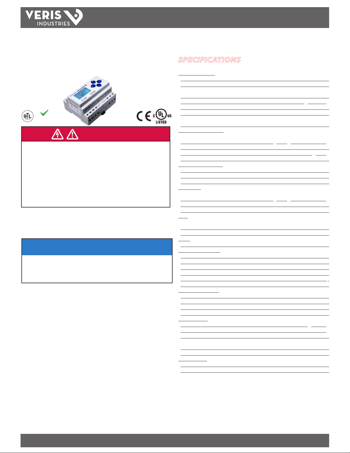
POWER MONITORING
INSTALLATION GUIDE
Compact Power and Energy Meter
With BACnet MS/TP Support
SPECIFICATIONS
Measurement A ccuracy:
Real Power and Energy IEC 62053-22 Class 0.5S, ANSI C12.20 0.5%
Reactive Power and Energy IEC 62053-23 Class 2, 2%
Current 0.4% (+0.015% per °C deviation from 25°C) from 5% to 100% of range;
0.8% (+0.015% per °C deviation from 25°C) from 1% to 5% of range
Volt age 0.4% (+0.015% per °C deviation from 25°C) from 90 V
n
C
e
A
t
B
·
®
·
T
S
E
E
S
I
T
R
I
O
N
RoHS
T
G
A
L
R
A
O
B
Compliant
Sample Rate 2520 samples per second
Data Update Rate 1 sec
Type of Measurement True RMS up to the 21st harmonic 60 Hz
One to three phase AC system
Input Voltage Characteristics:
DANGER
HAZARD OF ELECTRIC SHOCK, EXPLOSION, OR ARC FLASH
• Follow safe electrical work practices. See NFPA 70E in the USA, or applicable local codes.
• This equipment must only be installed and serviced by qualified electrical personnel.
• Read, understand and follow the instructions before installing this product.
• Turn off all power supplying equipment before working on or inside the equipment.
• Any covers that may be displaced during the installation must be reinstalled
before powering the unit.
• Use a properly rated voltage sensing device to confirm power is off.
DO NOT DEPEND ON THIS PRODUCT FOR VOLTAGE INDICATION
Failure to follow these instructions will result in death or serious injury.
A qualied person is one who has skills and knowledge related to the construction and
operation of this electrical equipment and the installation, and has received safety
training to recognize and avoid the hazards involved. NEC2009 Article 100
No responsibility is assumed by Veris Industries for any consequences arising out of the
use of this material.
Measured AC Voltage Minimum 90 V
UL Maximums: 600 V
Metering Over-Range +20%
Impedance 2.5 MΩ
Frequency Range 45 to 65 Hz
Input Current Characteristics:
CT Scaling Primary: Adjustable from 5 A to 32,000 A
Measurement Input Range 0 to 0.333 VAC or 0 to 1.0 VAC (+20% over-range)
Impedance 10.6 kΩ (1/3 V mode) or 32.1 kΩ (1 V mode)
Control Power:
AC 5 VA max.; 90 V min.
UL Maximums: 600 V
DC* 3 W max.; UL and CE: 125 to 300 VDC
Ride Through Time 100 msec at 120 VAC
Input:
Pulse Solid-state or mechanical contacts (current less than 1 mA);
2 pulse inputs)
Minimum Pulse Width 20 msec
Output:
(347 V
L-L
(347 V
L-L
L-N
(156 V
L-N
L-N
) for stated accuracy;
L-L
); CE Maximum: 300 V
); CE Maximum: 300 V
RS-485 Port 2-wire, 9600 to 115.2 kbaud, BACnet MS/TP
NOTICE
Mechanical Characteristics:
Weight 0.62 lb (0.28 kg)
• This product is not intended for life or safety applications.
• Do not install this product in hazardous or classified locations.
• The installer is responsible for conformance to all applicable codes.
• Mount this product inside a suitable fire and electrical enclosure.
FCC PART 15 INFORMATION
NOTE: This equipment has been tested by the manufacturer and found to
comply with the limits for a class B digital device, pursuant to part 15 of
against harmful interference when the equipment is operated in a
IP Degree of Protection (IEC 60529) IP40 front display; IP20 Meter
Display Charac teristics Back-lit blue LCD
Terminal Block Screw Torque 0.37 ft-lb (0.5 N·m) nominal/0.44 ft-lb (0.6 N·m) max.
Terminal Block Wire Size 24 to 14 AWG (0.2-2.1 mm2)
Rail T35 (35 mm) DIN Rail per EN50022
Environmental Conditions:
Operating Temperature -30° to 70°C (-22° to 158°F)
Storage Temperature -40° to 85°C (-4 0° to 185°F)
Humidity Range <95% RH (non-condensing)
Altitude of Operation 3 km max.
radio frequency energy and, if not installed and used in accordance with
the instruction manual, may cause harmful interference to radio
communications. This device complies with part 15 of the FCC Rules.
Operation is subject to the following two conditions:
(1) This device may not cause harmful interference, and
(2) this device must accept any interference received, including
interference that may cause undesired operation.
Modifications to this product without the express authorization of the
manufacturer nullify this statement.
For use in a Pollu tion Degree 2 or bet ter environment only. A Pollut ion Degree 2 environme nt must
control conductive pollution and the possibility of condensation or high humidity. Consider the
enclosure, t he correct use of ven tilation, thermal pro perties of the equ ipment, and the relatio nship
with the env ironment. Installat ion category: CAT II or C AT III
Metering Category:
North America CAT III; for distribu tion systems up to 347 V
CE CAT III; for distribution systems up to 300 V
Dielectric Withs tand Per UL 508, EN61010
Conducted and Radiated Emissions FCC part 15 Class B, EN55011/EN61000 Class B
(residential and light indus trial)
Conducted and Radiated Immunity EN61000 Class A (heavy industrial)
Agency Approvals:
US and Canada (cULus) UL508 (open ty pe device)/CSA 22.2 No. 14-05
Europe (CE) EN61010-1:2001
* External DC current limiting is required, see fuse recommendations.
Provide a dis connect device to dis connect the meter f rom the supply source. P lace this device
in close pr oximity to the equipm ent and within easy reac h of the operator, and mark it as t he
disconnec ting device. The disc onnecting device sh all meet the relevant re quirements of IEC 609 471 and IEC 60947-3 and shall be su itable for the applic ation. In the US and Canada, dis connecting
fuse hold ers can be used. Prov ide overcurrent prote ction and discone cting device for sup ply
conduct ors with approved cu rrent limiting device s suitable for prote cting the wiring. I f the
equipment i s used in a manner not spec ied by the manufac turer, the protection p rovided by the
device may be im paired.
ZL 0115- 0A PAGE 1 ©2013 For technical support please contact 01132
DE T-785 our GE tech suppor t team at 1-800-GE-1-STOP (1-800-431-7867)
to 600 VAC
L-N
L-N
/600 VAC
L-N
/5 MΩ
L-L
L-N
L-L
L-N
L-L
L-N
Page 2
AMP1H5
TM
INSTALLATION GUIDE
TABLE OF CONTENTS
Operation 2
Product Identication 2
Dimensions 2
Product Diagram 3
Installation 3
Supported System Types 4
Wiring Symbols 4
Data Outputs 2
Wiring Diagrams 5
Control Power Diagrams 6
Display Screen Diagram 7
Quick Setup Instructions 7
Pulse Contac ts 8
User Interface Menu Abbreviations Dened 8
User Interf ace for Data Conguration 9
Alert/Reset Information 10
User Interf ace for Setup 11
RS-485 Communications 13
Data Logging 13
BACnet Default Settings 13
BACnet Programming Information 14
Data Logging 22
Troubleshooting 24
China RoHS Compliance Information 24
PRODUCT IDENTIFICATION
Model
AMP 1H5
BACnet MS/TP
Protocol Output
n n n
Alarm
Output
Full Data
Set
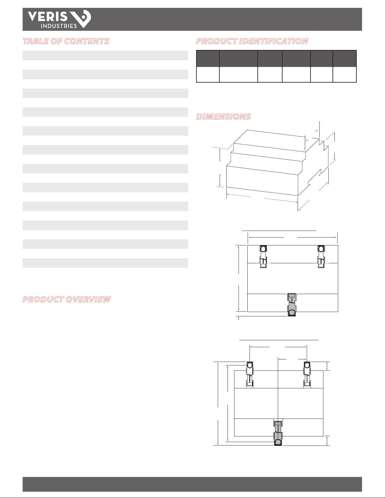
DIMENSIONS
2.3”
(59mm)
4.2”
(107mm)
Bottom View (DIN Mount Option)
4.2 “
(107 mm)
3.6 “
(91 mm)
Logging
1.8”
(45mm)
(39mm)
3.6”
(91mm)
1.5”
Data
Pulse
Input
n
(2 pulses)
1.9”
(48mm)
PRODUCT OVERVIEW
4.3 “
(109 mm)
0.2 “
(4 mm)
Bottom View (Screw Mount Option)
2.4 “
(61 mm)
3.9“
(99 mm)
1.2 “
(31 mm)
+
++
0.3 “
(8 mm)
0.4 “
(10 mm)
The AMP1H5 DIN rail power meter provides a solution for measuring energy data with
a single device. Inputs include control power, CT, and 3-phase voltage. The meter
supports BACnet MS/TP protocol and has data logging capability and two pulse
contact inputs. The LCD screen on the faceplate allows instant output viewing.
The meter is housed in a plastic enclosure suitable for installation on T35 DIN rail
according to EN50022. It can be mounted with any orientation over the entire
ambient temperature range, either on a DIN rail or in a panel. The AMP1H5 meter is
not sensitive to CT orientation, reducing installation errors.
ZL 0115- 0A PAGE 2 ©2013 For technical support please contact 01132
DE T-785 our GE tech suppor t team at 1-800-GE-1-STOP (1-800-431-7867)
Page 3
AMP1H5
TM
INSTALLATION GUIDE
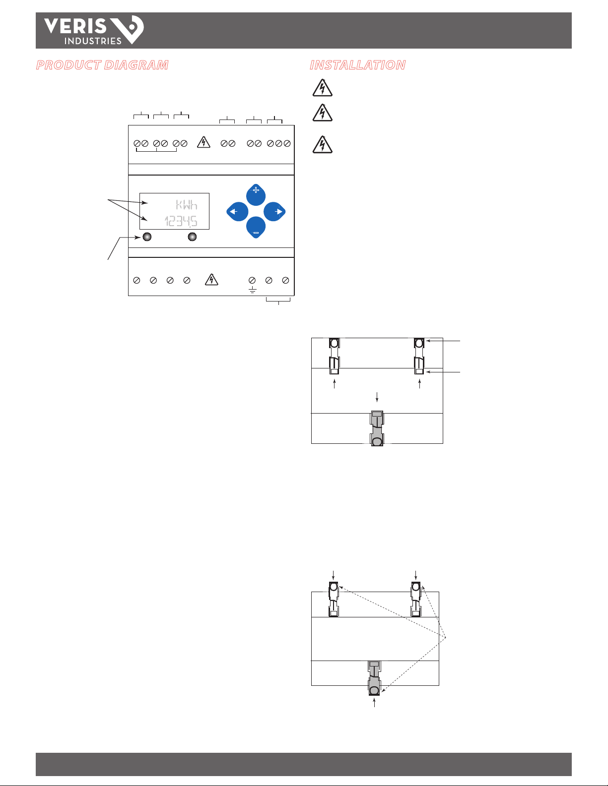
PRODUCT DIAGRAM
IA
-+-+-
A B C Pulse Inputs
Common - 1 or 1/3 VAC Input
Two 5-character rows
of display text.
Top row alphanumeric;
Bottom row numeric only
Alarm Energy
The red Alarm LED lights
when any of the 3 phase
voltages drop below the
selected threshold.
The green Energy LED lights
when the pulse 1 input
contacts are active or closed.
VOLTAGE INPUTS
CAT III 50/60 Hz
A B C N 1 2
VA
VB
INSTALLATION
Disconnect power prior to installation.
IB
IC
+
Pulse Input 1
Pulse Input 2
BACnet
RS-485
1 2 + - S
Shield
+
–
UL: 90V
- 600V
CE: 90V
L-N
VC
Neutral
- 300V
L-L
L-N
L-N
CONTROL POWER
0.1A 50/60 Hz
Earth
Control
Power
Reinstall any covers that are displaced during the
installation before powering the unit.
Mount the meter in an appropriate electrical enclosure
near equipment to be monitored.
Do not install on the load side of a Variable Frequency Drive
(VFD), aka Variable Speed Drive (VSD) or Adjustable Frequency
Drive (AFD).
The meter can be mounted in two ways: on standard 35 mm DIN rail or screwmounted to the interior surface of the enclosure.
A. DIN Rail Mounting
1. Attach mounting clips to the underside of the housing by sliding them into the
slots from the inside. The stopping pegs must face the housing, and the outside
edge of the clip must be ush with the outside edge of the housing.
2. Snap the clips onto the DIN rail. See diagram of the underside of the housing
(below).
Clip flush with
outside edge
Snap onto
Insert clips from inside
DIN rail
3. To prevent horizontal shifting across the DIN rail, use two end stop clips.
B. Screw Mounting
1. Attach the mounting clips to the underside of the housing by sliding them into the
slots from the outside. The stopping pegs must face the housing, and the screw
hole must be exposed on the outside of the housing.
2. Use three #8 screws (not supplied) to mount the device to the inside of the
enclosure. See diagram of the underside of the housing (below).
Insert clips from outside
Screw holes
exposed for
mounting
ZL 0115- 0A PAGE 3 ©2013 For technical support please contact 01132
DE T-785 our GE tech suppor t team at 1-800-GE-1-STOP (1-800-431-7867)
Page 4
AMP1H5
TM
INSTALLATION GUIDE
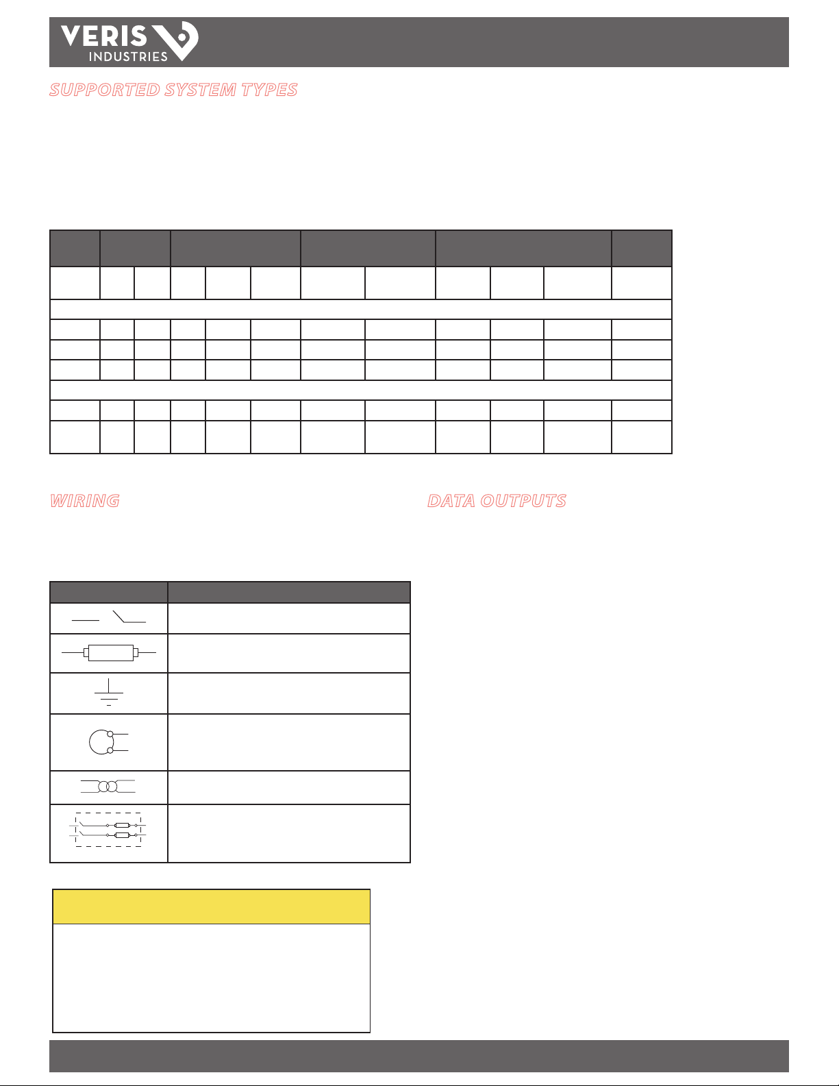
SUPPORTED SYSTEM TYPES
The AMP1H5 power meter has a number of dierent possible system wiring congurations (see Wiring Diagrams, page 5). To congure the meter, set the System Type via the
User Interface or by writing the Present_Value of AV2 with the System Type value in the table below. The System Type tells the meter which of its current and voltage inputs
are valid, which are to be ignored, and if neutral is connected. Setting the correct System Type prevents unwanted energy accumulation on unused inputs, selects the formula
to calculate the Theoretical Maximum System Power, and determines which phase loss algorithm is to be used. The phase loss algorithm is congured as a percent of the Lineto-Line System Voltage (except when in System Type 10) and also calculates the expected Line to Neutral voltages for system types that have Neutral (12 & 40).
Values that are not valid in a particular System Type will display as “----” on the User Interface or as QNAN in the BACnet objec ts.
CTs Voltage Connections System Type Phase Loss Measurements Wiring
Diagram
Number
of wires
Single-Phase Wiring
2 1 A 2 A, N L-N 10 1L + 1n AN 1
2 1 A 2 A, B L- L 11 2L AB 2
3 2 A, B 3 A, B, N L-L with N 12 2L + 1n AB AN, BN AN-BN 3
Three-Phase Wiring
3 3 A, B, C 3 A, B, C Delta 31 3L AB, BC, CA A B- BC- CA 4
4 3 A, B, C 4 A, B, C, N Grounded
Qty ID Qty ID Type BACnet object
AV2
40 3L + 1n AB, BC, CA AN, BN, CN AN-BN-CN &
Wye
User Interf ace:
SE TU P>S SY S
VLL VLN Balance Diagram
number
5, 6
AB -B C-C A
WIRING
To avoid distortion, use parallel wires for control power and voltage inputs.
The following symbols are used in the wiring diagrams on the following pages.
Symbol Description
Voltage Disconnect Switch
Fuse (installer is responsible for ensuring compliance with
local requirements. No fuses are included with the meter.)
Earth ground
S1
S2
Current Transducer
Potential Transformer
Protection containing a voltage disconnect s witch with a
fuse or disconnect circuit breaker. The protection device
must be rated for the available short-circuit current at the
connection point.
CAUTION
RISK OF EQUIPMENT DAMAGE
• This product is designed only for use with 1V or 0.33V current
transducers (CTs).
• DO NOT USE CURRENT OUTPUT (e.g. 5A) CTs ON THIS PRODUCT.
• Failure to follow these instructions can result in overheating and
permanent equipment damage.
DATA OUTPUTS
Full Data Set (FDS):
Power (kW)
Energy (kWh)
Congurable for CT & PT ratios, system type, and passwords
Diagnostic alerts
Current: 3-phase average
Volts: 3-phase average
Current: by phase
Volts: by phase Line-Line and Line-Neutral
Power: Real, Reactive, and Apparent 3-phase total and per phase
Power Factor: 3-phase average and per phase
Frequency
Power Demand: Most Recent and Peak
Demand Conguration: Fixed, Rolling Block, and External Sync
Real Time Clock: uses BACnet Time Synchronization services
Data Logging (includes all FDS outputs, plus):
3 BACnet Log_Events: each buer holds 5760 time-stamped 32-bit entries
(User congures which 3 data points are stored in these buers)
User congurable logging interval
(When congured for a 15 minute interval, each buer holds 60 days of
data)
Continuous and Single Shot logging modes: user selectable
ZL 0115- 0A PAGE 4 ©2013 For technical support please contact 01132
DE T-785 our GE tech suppor t team at 1-800-GE-1-STOP (1-800-431-7867)
Page 5
TM
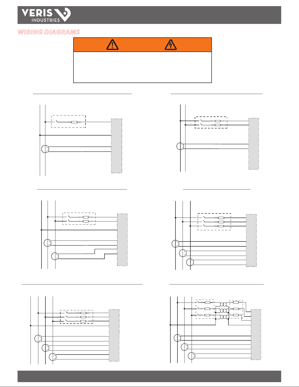
WIRING DIAGRAMS
RISK OF ELECTRIC SHOCK OR PERMANENT EQUIPMENT DAMAGE
CT negative terminals are referenced to the meter’s neutral and may be at elevated voltages
· Do not contact meter terminals while the unit is connected
· Do not connect or short other circuits to the CT terminals
Failure to follow these instructions may cause injury, death or equipment damage.
Diagram 1: 1-Phase Line-to-Neutral 2- Wire System 1 CT Diagram 2: 1-Phase Line-to-Line 2-Wire System 1 CT
USE SYSTEM TYPE 10 (1L + 1n)
N L1
AMP1H5
WARNING
INSTALLATION GUIDE
USE SYSTEM TYPE 11 (2L)
L1 L2
A
B
C
N
X1
X2
White
Black
+
A
-
+
B
-
+
C
-
Diagram 3: 1-Phase Direct Voltage Connection 2 CT
N
L1 L2
USE SYSTEM TYPE 12 (2L + 1n) USE SYSTEM TYPE 31 (3L)
A
B
C
N
X1
X2
X1
X2
White
Black
White
Black
+
A
-
+
B
-
+
C
-
X1
X2
Diagram 4: 3-Phase 3-Wire 3 CT no PT
L1 L2 L3
X1
X1
X2
X1
X2
X2
White
Black
White
Black
White
Black
White
Black
A
B
C
N
+
A
-
+
B
-
+
C
-
A
B
C
N
+
A
-
+
B
-
+
C
-
Diagram 5: 3-Phase 4-Wire Wye Direct Voltage Input Connection 3 CT
L1N L2 L3
X1
X2
USE SYSTEM TYPE 40 (3L + 1n)
X1
X2
X1
X2
White
Black
White
Black
White
Black
A
B
C
N
+
A
-
+
B
-
+
C
-
Diagram 6: 3-Phase 4-Wire Wye Connection 3 CT 3 PT
L1N L2 L3
X1
X2
USE SYSTEM TYPE 40 (3L + 1n)
White
X1
X2
X1
X2
Black
White
Black
White
Black
A
B
C
N
+
A
-
+
B
-
+
C
-
ZL 0115- 0A PAGE 5 ©2013 For technical support please contact 01132
DE T-785 our GE tech suppor t team at 1-800-GE-1-STOP (1-800-431-7867)
Page 6
TM
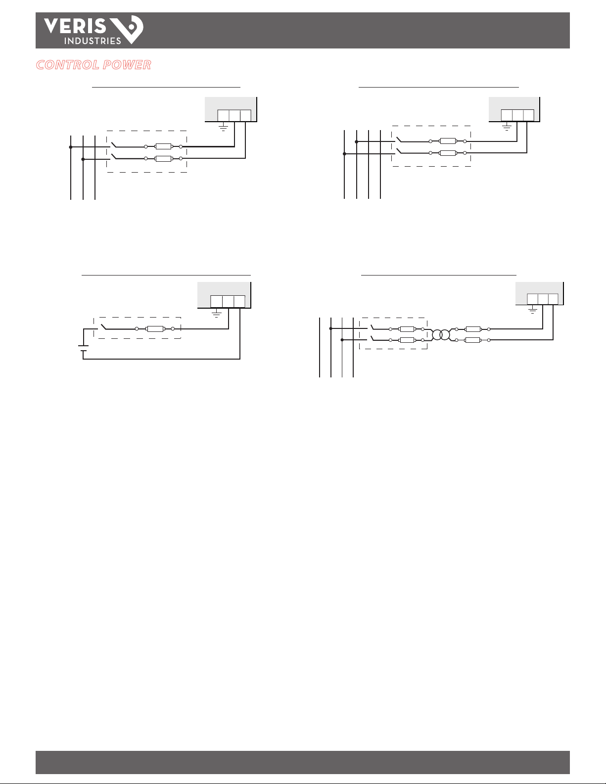
CONTROL POWER
AMP1H5
INSTALLATION GUIDE
Direct Connect Control Power (Line to Line)
1 2G
L1
L2 L3
Line to Line from 90 VAC to 600 VAC (UL) (520 VAC for CE). In UL installations the lines may be
oating (such as a delta). If any lines are tied to an earth (such as a corner grounded de lta), see the
Line to Neutral installation limi ts. In CE compliant installations, the lines must be neut ral (earth)
referenced at less than 300 VAC
L-N
Direct Connect Control Power (DC Control Power)
1 2G
Direct Connect Control Power (Line to Neutral)
1 2G
L1N L2 L3
Line to Neutral from 90 VAC to 347 VAC (UL) or 300 VAC (CE)
Control Power Transformer (CPT) Connection
1 2G
L1N L2 L3
Fuse Recommendations:
Keep the fuses close to the power source (obey local and national code requirements).
For selecting fuses and circuit breakers, use the following criteria:
• Select current interrupt capacity based on the installation category and
fault current capability.
• Select over-current protection with a time delay.
• Use a voltage rating sucient for the input voltage applied.
• Provide overcurrent protection and disconnecting means to protect
the wiring. For DC installations, provide external circuit protection.
Suggested: 0.5A, high-interrupt capability time delay fuses rated for DC
operation at or above the supply voltage.
• The earth connec tion is required for electromagnetic compatibility (EMC)
and is not a protective earth ground.
The Control Power Transformer may be wired L-N or L-L. Output to meet meter input requirementsDC Control Power from 125 VDC to 300 VDC (UL and CE max.)
ZL 0115- 0A PAGE 6 ©2013 For technical support please contact 01132
DE T-785 our GE tech suppor t team at 1-800-GE-1-STOP (1-800-431-7867)
Page 7
TM
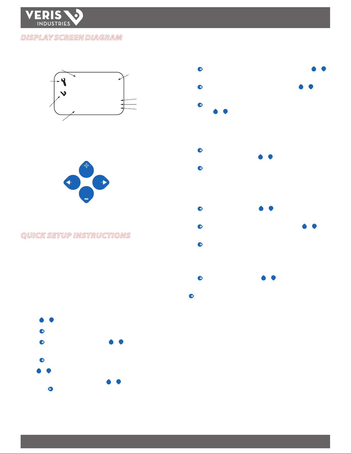
DISPLAY SCREEN DIAGRAM
LCD Screen:
Screen Name or Units
Diagnostic Alert:
indicates that one or
more of the alarm
bits (Binary_Objects
1-15) are active.
Logo
Numeric Data
Buttons:
(Up)
Select
♥
Tx
Rx
ERR
+
AMP1H5
Alive Indicator
RS-485 Equipped Units Only:
Transmit Data
Receive Data
Receive Data Error
INSTALLATION GUIDE
B. To Enter BACnet communication parameters
1. Navigate to the S BAC (set BACnet) Setup screen (see section A above).
+
2. Press to go to the MAC screen and through the address digits. Use
to select the BACnet MAC address (default is 0 01 ).
3. Press to accept the value and go to the KBAUD screen. Use
the baud rate (default is 76. 8K).
4. Press to go to the ID1 screen and through the upper four digits of the Device
Instance. Use
+
+
or – to select the ID digits. The setup screen splits the Device
ID into two parts, the most signicant four digits (ID1) and the least signicant
three digits (ID2). The AMP1H5 supports BACnet Device ID values from 1 to
4,193,999. Units are shipped with a factory default setting that is pseudorandomly generated in the range from 1,000,000 to 3,097,151.
5. Press to accept the value and go to the ID 2 screen and through the lower
three digits of the Device Instance. Use
+
+
or – to select the ID digits.
6. Press to accept the value and go back to the S BAC screen.
+
or –
+
+
or – to select
(Left)
Back
(Right)
Next
–
(Down)
Select
QUICK SETUP INSTRUCTIONS
Use this section to enter:
- BACnet communication parameters
- CT (Current Transducer) output voltage and input current ranges
- The service type to be monitored
These instruc tions assume the meter is set to factory defaults. If it has been
previously congured, check all optional values.
A. To Navigate to the Setup screens:
+
+
1. Press
2. Press to get to the PAS WD screen.
3. Press to move through the digits. Use the
or – repeatedly until SETU P screen appears.
password (the default is 00000).
+
+
or – buttons to enter your
C. To Enter the CT output voltage and input current ranges:
1. Navigate to the S CT (Set Current Transducer) Setup screen (see section A
above).
+
2. Press to go to the CT V screen. Use
+
or – to select the voltage mode
Current Transducer output voltage (default is 1. 00).
+
3. Press to go to the CT SZ screen and through the digits. Use
+
or – to
select the CT size in amps (default is 100). accept the value and
4. Press to accept the value and go back to the S CT screen.
D. To Enter the service type to be monitored:
1. Navigate to the S SYS (Set System) Setup screen (see section A above).
+
2. Press to go to the SY STM screen. Use
(see wiring diagrams - default is 3LN-1N).
Press to go back to the S SYS screen. For full setup instructions, see the
conguration instructions on the following pages.
+
or – to select the conguration
4. Press to move to the rst Setup screen (S BAC)
+
+
5. Use
or – to select the parameter screen you want to set.
+
6. After you set the parameters you want, use
+
or – to select the next Setup
screen or to exit the Setup screens (return to S ETU P).
ZL 0115- 0A PAGE 7 ©2013 For technical support please contact 01132
DE T-785 our GE tech suppor t team at 1-800-GE-1-STOP (1-800-431-7867)
Page 8
AMP1H5
TM
INSTALLATION GUIDE
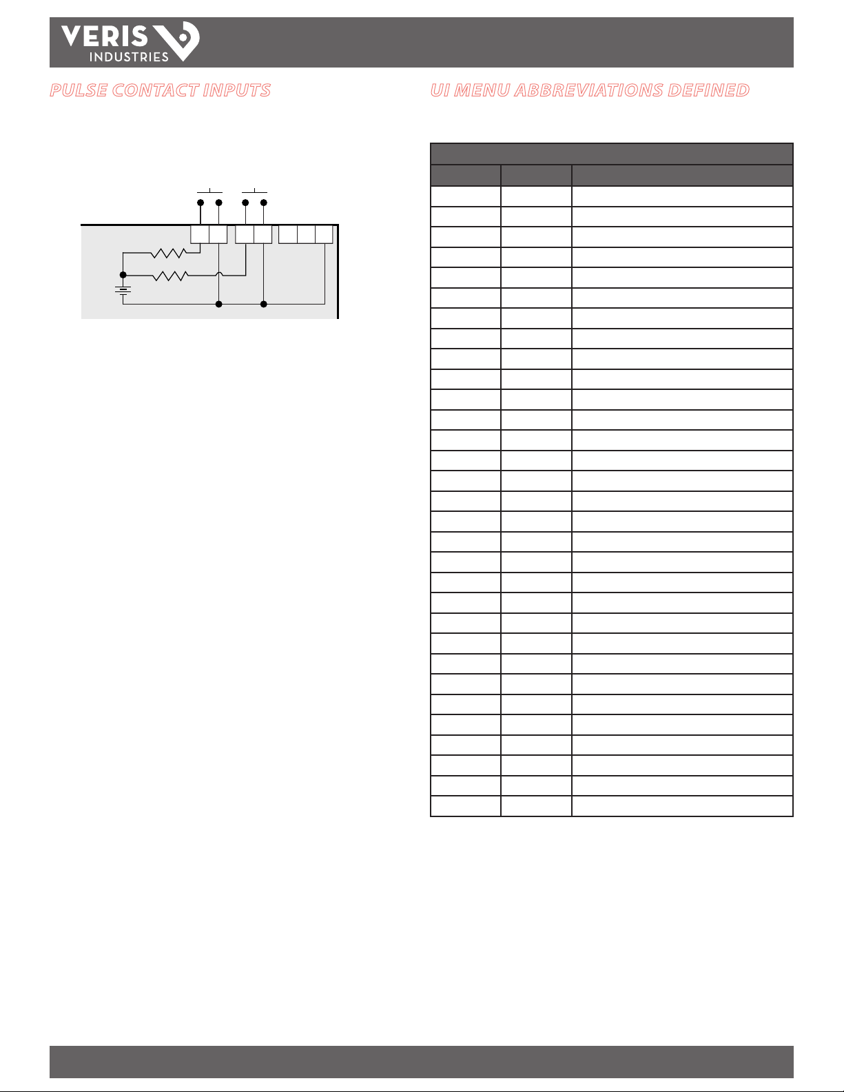
PULSE CONTACT INPUTS
The AMP1H5 has two inputs with pulse accumulators for solid state or mechanical
contacts in other sensors, such as water or gas ow meters. These inputs are isolated
from the measured circuits and referenced to the communication signal ground. Use
with contacts that do not require current to remove oxidation.
Pulse Input
Contacts
SComm
Output
Comm
Ground
Equivalent
Circuit
4-10 VDC
nominal
~10 kΩ
+
UI MENU ABBREVIATIONS DEFINED
The user can set the display mode to IEC or IEEE notation in the SETUP menu.
Main Menu
IEC IEEE Description
D D Demand
MAX M Maximum Demand
P W Present Real Power
Q VAR Present Reactive Power
S VA Present Apparent Power
A A Amps
UAB, UBC, UAC VAB, VBC , VAC Voltage Line to Line
V VLN Voltage Line to Neut ral
PF PF Pow er Factor
U VLL Voltage Line to Line
HZ HZ Frequenc y
KSh K VAh Accumulated Apparent Energy
KQh KVA Rh Accumulated Reactive Energy
KPh KWh Accumulated Real Energy
PLOSS PLOSS Phase Loss
LOWPF LOWPF Low Power Factor Error
F ERR F ERR Frequency Error
I OVR I OVR Over Current
V OVR V OVR Over Voltage
PULSE PULSE kWh Pulse Output Overrun (conguration error)
_PHASE _PHASE Summar y Data for 1, 2, or 3 active phases
ALERT ALERT Diagnostic Alert Status
INFO INFO Unit Information
MODEL MODEL Model Number
OS OS Operating System
RS RS Reset System
SN SN Serial Number
RESET RESET Reset Data
PASWD PAS WD Enter Reset or Setup Pass word
ENERG ENERG Reset Energy Accumulators
DEMND DEMND Reset Demand Maximums
ZL 0115- 0A PAGE 8 ©2013 For technical support please contact 01132
DE T-785 our GE tech suppor t team at 1-800-GE-1-STOP (1-800-431-7867)
Page 9

AMP1H5
TM
USER INTERFACE FOR DATA CONFIGURATION
_PHAS
HZ
Frequency
INSTALLATION GUIDE
M KVA
MKVAR
M KW
DEMND
Maximum
Demand (S)
Apparent Power
Maximum
Demand (Q)
Reactive Power
Maximum
Real Power
Demand (P)
CPHAS
C KWh
C PF
C KVA
CKVAR
C KWC VLN
BPHAS
B KWh
B PF
B KVA
APHAS
A KWh
A PF
A KVA
3 KWh
Real Energy
Accumulated
3 PF
(Average of
Power Factor
Active Phases)
Power (S)
3 KVA
Total Apparent
ENRGY
3KVAR
BKVAR
AKVAR
Power (Q)
Total Reactive
PULS2
Pulse Counter 2
(not used on E50H2)
>>> Scroll When Idle >>>
Power (P)
Total Real
B KWB VLN
A KW
3 KW
PULS1
Input Pulse Counter
KVAh
Accumulated
Apparent Energy
KVARh
Accumulated
Reactive Energy
KWh
Real Energy
Accumulated
ENRGY
and Counters
Accumulators
(Sh)
(Qh)
(Ph)
To:
ALERT
To:
Present
D KVA
Demand (S)
Apparent Power
Present
Demand (Q)
DKVAR
Reactive Power
Present
Real Power
Demand (P)
D KW
SETUP
DEMND
Demand
C VAC
C A
CPHAS
3 Phase
Phase C:
B VBC
B A
BPHAS
Phase B:
2 & 3 Phase
Systems Only
A VLN
A VAB
A A
APHAS
Phase A:
Systems Only
All Systems
1, 2, or 3 Phase
3 VLN
Volts Line-Neutral (V)
3 VLL
Volts Line-Line (U)
3 A
Amps (A)
_PHAS
Summary Data
Phases)
(Average of Active
Phases)
(Average of Active
(Average of
Active Phases)
Energy
ZL 0115- 0A PAGE 9 ©2013 For technical support please contact 01132
DE T-785 our GE tech suppor t team at 1-800-GE-1-STOP (1-800-431-7867)
Page 10

TM
ALERT/RESET INFORMATION
To: ENRGY
AMP1H5
INSTALLATION GUIDE
Alert Status
(check if
Wrench on
LCD)
Unit
Information
Reset
Data
Setup
Meter
ALERT
INFO
RESET
SETUP
PLOSS
-------A b C
Phase Loss
A B C
LOWPF
-------A b C
Low Power Factor
A B C
F ERR
-------A
Frequency Out
of Range
A
Display “nOnE” if no alerts
MODEL OS SNRS
Model
Number
Operating
System
Reset
System
Back
PASWD
--------
0
0000
Enter Reset
Password
ENERG
--------
rES
Reset Energy
Accumulators to 0
Reset Demand
Maximums to Present
PASWD
--------
0
0000
Enter Setup
Password
DEMND
--------
rES
I OVR
-------A b C
Over Current
(Clipping)
A B C
Serial
Number
COUNT
rES
Reset Pulse
Counters to 0
--------
V OVR
-------A b C
Over Voltage
(Clipping)
A B C
INFO
RESET
To Setup
PULSE
------- Error
Energy Pulse Output:
Error = Overrun Error
ConF = Configuration Error
ALERT
PASWD – Enter the Reset Password
(configured in the setup menu).
ENERG – Reset all Energy
Accumulators (Wh, VARh, VAh) to 0.
Press “+” or “-“ to Reset.
DEMND – Reset all Maximum
Demand (W, VAR, VA) to the present
Demand. Press “+” or “-“ to Reset.
COUNT – Reset the pulse counters.
Press “+” or “-“ to Reset.
To: DEMND
ZL 0115- 0A PAGE 10 ©2013 For technical support please contact 01132
DE T-785 our GE tech suppor t team at 1-800-GE-1-STOP (1-800-431-7867)
Page 11

TM
USER INTERFACE FOR SETUP
To: SPASS
AMP1H5
INSTALLATION GUIDE
Back
From:
SETUP > PASWD
Back
Current
Transformer
Back
System
Type
Back
Potential
Back To SETUP
Transformer
Back
Sytem
Voltage
Back
Sytem
Voltage
S BAC
S CT
S SYS
S PT
S V
S PWR
MAC
--------
0
01
--------
SYSTM
--------
3L-1n
3L
2L-1n
2L
1L+1n
MX KW
103.92
CT V
1.0
.33
RATIO
--------
001
.00
V LL
--------
00480
--------
Next
Next
Next
Next
KBAUD
--------
115.2
76.8
38.4
19.2
9.6
CT SZ
--------
200
Next
ID1
--------
0
000
Next
ID2
--------
00
0
Set Communications Parameters:
ADDR – BACnet MS/TP MAC Address: 0 – 127.
+ increments the selected (blinking) digit.
– selects the digit to the left.
BAUD - Baud Rate: 9600 – 115200 Baud
BACnet ID: These two screens set the 7 digit
BACnet device ID. Screen ID1 is the most
significant 4 digits and ID2 the least significant
three digits. This is in the range of 0 - 4,194,302.
Set Current Transducer:
CT V - CT Input Voltage: + or – to Select 1.0 or .33V.
CT SZ - CT Size: in Amps. Maximum is 32000 Amps.
Set System Configuration:
SYSTM: + or – to step through the following System Type options:
Reg 130 CTs Description
System
3L-1n 40 3 Wye Three Phase: A, B, & C with Neutral (Default).
3L 31 3 Delta Three Phase: A, B & C; no Neutral
2L-1n 12 2 Single Split Phase: A & B with Neutral
2L 11 1 Single Phase: A & B; no Neutral
1L-1n 10 1 Single Phase: A to Neutral
Set Potential Transfomer Ratio:
RATIO – Potential transformer step down is RATIO:1. Default is 1:1
(No PT installed). See Install for wiring diagrams. This value must be
set before the System Voltage (if used).
Set System Voltage:
V LL – The nominal Line to Line Voltage for the system. This is used
by the meter to calculate the theoretical maximum system power, and
as the reference voltage for setting the Phase Loss threshold.
Maximum is 32000 Volts. For system type 1+N (10), this is a Line to
Neutral Voltage, indicated by “V LN”. Note: the meter will reject settings
that are not within the meter’s operating range when divided by the PT
ratio.
System Power:
MX KW – The theoretical Maximum System Power is calculated by the
meter from the System Voltage, CT size, and System Type. Power
Factor is assumed to be unity. The value of System Power is used to
determine which combinations of pulse weight and duration are valid
and will keep up with the maximum power the meter will see. This value
is read only.
To Setup p. 2 “SPLOS”
Note: Bold is the Default.
ZL 0115- 0A PAG E 11 ©2013 For technical support please contact 01132
DE T-785 our GE tech suppor t team at 1-800-GE-1-STOP (1-800-431-7867)
Page 12

AMP1H5
TM
INSTALLATION GUIDE
To Setup p. 1 “S PWR”
Back
Back
SPLOS
Phase
Loss
SDMND
Demand
VOLTS
--------
0.1
0
INTRV
-------6
5
4
3
2
1
IMBAL
--------
0.2
Next
SEC
--------
0
0900
Next
Set Phase Loss:
VOLTS - Phase Loss Voltage: The fraction of the system
voltage below which Phase Loss Alarm is on. For system
types with neutral, the Line to Neutral voltage is also
calculated and tested. If the System Voltage is 600 and the
fraction is set to 0.10, then the Phase Loss threshold will be
5
60 volts.
IMBAL - Phase Loss Imbalance: The fractional difference
in Line to Line voltages above which Phase Loss Alarm is
on. For system types with neutral, the Line to Neutral
voltages are also tested. For system types 1+N (10) and 2
(11) , imbalance is not tested.
Set Demand Interval:
INTRV - The number of Sub-Intervals (1 to 6) in a
Demand Interval. Default is 1 (block demand).
SEC - Sub-Interval length in seconds. Default is
900 (15 minutes). Set to 0 for external sync-tocomms.
Back
Back
Passwords
To Setup page 1 “S BAC”
S DIS
Display
Units
SPASS
Setup
UNITS
--------
IEEE
IEC
Next
SETUP
--------
0
0000
RESET
--------
0
0000
Next
Set Display Units: +/- to switch between:
IEEE – VLL VLN W VAR VA Units.
IEC - U V P Q S Units.
Set Passwords:
SETUP - The Password to enter the SETUP menu.
RESET - The Password to enter the RESET menu.
ZL 0115- 0A PAGE 12 ©2013 For technical support please contac t 01132
DE T-785 our GE tech suppor t team at 1-800-GE-1-STOP (1-800-431-7867)
Page 13

AMP1H5
Red
Black
Gray
Use 14-24 gauge wire
TM
INSTALLATION GUIDE
RS-485 COMMUNICATIONS
Daisy-chaining Devices to the Power Meter
The RS-485 slave port allows the power meter to be connected in a daisy chain with
up to 63 2-wire devices.
120 Ω terminator on the rst an d last device
of the daisy chai n
+
–
S
Shield wire
NOTES:
• The terminal’s voltage and current ratings are compliant with the
requirements of the EIA RS-485 communications standard.
• The RS-485 transceivers are ¼ unit load or less.
• RS-485+ has a 47 kΩ pull up to +5V, and RS-485- has a 47 kΩ pull down
to Shield (RS-485 signal ground).
• Wire the RS-485 bus as a daisy chain from device to device, without
any stubs. Use 120 Ω termination resistors at each end of the bus (not
inc luded).
• Shield is not internally connected to Earth Ground.
• Connect Shield to Earth Ground somewhere on the RS-485 bus.
For all terminals:
• When tightening terminals, apply the correct torque: 0.37 to 0.44 ft·lb
(0.5 to 0.6 N·m).
• Use 14-24 gauge(2.1-0.2 mm2) wire for all connections.
0.37–0.44 ft•lb
(0.5–0.6 N•m)
BACNET DEFAULT SETTINGS
Setting Default Value* BACnet Object
Setup Password 00000 n/a
Reset Password 00000 n/a
System Type 40 (3 + N) Wye AV2
CT Primar y Ratio 200 A AV3
CT Secondary Ratio 0.33 V AV4
PT Ratio 1:1 (none) AV5
System Voltage 480 V L-L AV6
Max. Theoretical Power Calculated f rom AV2, AV3,
Display Mod e 1 (IEEE Units) AV 7
Phase Loss Voltage
Threshold
Phase Loss Voltage
Threshold
Demand: number of
subintervals per interval
Demand: sub-interval
length
BACnet MAC Address 001 n/a
BACnet MS/TP B aud Rate 76.8 kBaud n/a
BACnet MS/TP Max_Master 127 Device
BACnet Device_ID Pseudo-random value
BACnet Device Location Installed location not yet
Trend_Log Obje ct 1
Log_Device_Object_
Property
Trend_Log Obje ct 2
Log_Device_Object_
Property
Trend_Log Obje ct 3
Log_Device_Object_
Property
AV5 & AV6 (with all default
settings, this would be
103.92 kW)
10% of System Voltage AV8
25% Phase to Phase
Imbalance
1 (block mode) AV 10
900 sec (15 min)
(AV11 default value is
90000 [1/100 seconds])
from 1,000,000 to
3, 097,151
identied
AI1 (Real Energy) TL1
AI27 (Reactive Ener gy) TL2
AI34 (Total Real Present
Demand)
AI45
AV9
AV11
Device
Device
TL3
* Default values are preset a t the factory. Once changed, there is no way to automatically reset
defaults. They must be restored i ndividually. The baud rate and MAC address are set through the
user-interface screens, and the others are set by re- writing each Object (see BACnet Programming
Information section, next page).
ZL 0115- 0A PAGE 13 ©2013 For technical support please contact 01132
DE T-785 our GE tech suppor t team at 1-800-GE-1-STOP (1-800-431-7867)
Page 14

AMP1H5
TM
INSTALLATION GUIDE
BACNET PROGRAMMING INFORMATION
The AMP1H5 is programmable via BACnet protocol and can easily be connected to a BACnet MS/TP network using an o-the shelf BACnet router. It uses ve types of BACnet
objects. A standard PICS (below) describes the required characteristics of the BACnet implementation, but this additional descriptive contex t may be helpful to the integrator.
In addition to the required properties, the device object utilizes some optional properties to support other functionality, Time Synchronization (primarily used for data/trend
logging on the device) and Description and Location properties to simplify installation and maintenance. Congure all of the meter’s functions, other than data logging and
writable Device Properties, by writing the Present_Value of the 11 Analog_Value objects. These values (except for the conguration register, AV1, which always returns zero
when read) are all readable and stored in nonvolatile memory so that they are retained if power to the device is interrupted.
Data values other than log information and alerts are all accessed by reading the Present_Value of the 52 Analog_Input objects. Most of these values are instantaneous
readings of measured ser vice parameters. Some of them, (AI1, AI26, AI27, AI37-AI45, AI47, AI50 and AI51) represent accumulated values and are stored in nonvolatile memory
as well. If power to the device is interrupted, these values are retained, but no additional information accumulates until the device completes its re-initialization.
Alerts are used to indicate conditions of potential concern to the installer or the system, such as input voltage or current on any phase that exceeds the meter’s measurement
range, phase voltage below the Phase Loss Threshold set by the user, or Power Factor below 0.5 on any phase. Alerts are accessible individually by reading the Present_Value
of the 15 Binary_Input objects or as a group by reading the Present_Value of Analog_Input object 52. Alerts are not latched and do not generate events to system. They
indicate presence of these conditions at the time they are read, but the device does not latch and store them until they are read (if the condition changes before they are read,
the alert will go away).
All Analog_Value, Analog_Input, and Binary_Input objects implement the reliability property and use it to indicate that the Present_Value properties are functional, valid
and current. For complete assurance, check the Reliabilt y property for a No_Fault_Detected status before reading the Present_Value of any AV, AI or BI objects.
The AMP1H5 data logging capability is implemented using three Trend_Log objects. These are described in more detail in the section on data logging.
BACnet Protocol Implementation Conformance Statement (PICS)
Date: January 1, 2013
Vendor Name: GE Industrial Solutions
Product Name: AMP1H5 Energy Meter
Product Model Number: AMP1H5
Applications Software Version: 1
Firmware Revision: x.xxx
BACnet Protocol Revision: 4
Product Description: 3-phase electrical energy meter
BACnet Standardized Device Profile (Annex L): BACnet Application Specic Controller (B-ASC)
List all BACnet Interoperability Building Blocks Supported (Annex K): DS-RP-B, DS-RPM-B, DS-WP-B, DM-DDB-B, DM-DOB-B, DM-DCC-B, T-VMT-I-B, DM-TS-B
Segmentation Capability: Segmentation not supported
Standard Object Types Supported: No dynamic Creation or Deletion supported; no proprietary properties or object types
1. Device Objec t:
Optional Properties Supported: Max_Master, Max_Info_Frames, Description, Location, Local_Time, Local_Date
Writable Properties: Object_Identier, Object_Name, Max_Master, Location
Property Range Restric tions: Object_Identier – May only write values from 1 to 4,193,999; Location – (limited to 64 characters); Max_Master – May only write
values from 1 to 127
2. Analog_Input Objects:
Optional Properties Supported: Description, Reliability
No Writable Properties.
ZL 0115- 0A PAGE 14 ©2013 For technical support please contact 01132
DE T-785 our GE tech suppor t team at 1-800-GE-1-STOP (1-800-431-7867)
Page 15

3. Analog_Value Objects:
Optional Properties Supported: Description, Reliability
Writable Properties: Only the Present_Value is writable.
Property Range Restric tions:
AV1: May only write 30078, 21211, 21212 and 16498.
AV2: May only write 10, 11, 12, 31 and 40.
AV3: May only write values from 5 to 32000.
AV4: May only write values 1 and 3.
AV5: May only write values from 0.01 to 320.0
AV6: May only write values such that AV6/AV5 is from 82 to 660 (absolute range is 82-32000). To ensure AV6 accepts/rejects the proper values, set AV5 rst.
AV7: May only write values 0 and 1.
AV8: May only write values from 1 to 99.
AV9: May only write values from 1 to 99.
AV10: May only write values from 1 to 6.
AV11: May only write the value 0 or a value from 1000 to 3276700 in multiples of 100.
The Record_Count of the Trend_Logs (TL1 to TL3) are reset when this object is written.
4. Binary_Input Objects:
Optional Properties Supported: Description, Reliability
No Writable Properties
5. Trend_Log Objects:
AMP1H5
TM
INSTALLATION GUIDE
Optional Properties Supported: Description,
Writable Properties: Log_Enable, Start_Time, Stop_Time, Log_DeviceObjectProper ty, Log_Interval, Stop_When_Full, Record_Count
Property Range Restric tions:
Log_DeviceObjectProperty: May only be set to the Present_Value of local objects AI1 through AI44 (only the Present_Value of objects AI1 through AI44 may be
logged).
Log_Interval: May only write the value 0 or values from 1000 to 3276700 in multiples of 100.
Data Link Layer Options: MS/TP master (Clause 9), baud rate(s): 9600, 19200, 38400, 76800, 115200
Device Address Binding: Static device binding is not supported. (No client functionality is included).
Networking Options: None
Character Sets Supported: ANSI X3.4
ZL 0115- 0A PAGE 15 ©2013 For technical support please contact 01132
DE T-785 our GE tech suppor t team at 1-800-GE-1-STOP (1-800-431-7867)
Page 16

AMP1H5
TM
INSTALLATION GUIDE
Legend
R/W R=read only; R/W=read or write
NV Value is stored in non-vol atile memory. The value are still available if the meter ex periences a power loss and reset.
Units Lists the physical un its that a register holds.
Device Object
Property R/W NV Value Returned Additional information
Object_Identier R/W NV Device<n> n is the 7 digit ID # set in the ID1 & ID2 setup screens on the meter. The BACnet
Object_Type R NV Device (8)
Object_Name R NV GE AMP1xx Series Energy Meter - S/N:
<serial number>
Vendor_Name R NV GE Industrial Solutions
Vendor_Identier R NV 276
Model_Name R NV AMP1H5 Energy Meter
Firmware_Revision R NV <Current Revision #> “xyyy”.
Application_Software_ Version R NV <Current version #> “RS= xyyy, OS=xyyy, BACnet Gateway=xyyy”
Location R/W NV <Loc ation> Limted to 64 Charac ters - Default value is “Installed lo cation not yet identied”
Description R NV GE AMP1H5 Energy Meter S/N: <serial
number>
Protocol_Version R NV 1 BACnet Protocol Version 1
Protocol_Revsion R NV 4 BACnet Protocol Revision 4
Local_Date R Date Set via BACnet Time Synchroniz ation only - reverts to Jan 1, 2000 if control power
Loc al_Time R Time Set via BACnet Time Synchronization only - reverts to 12:00:00 AM if control power
Segmentation_Supported R NV N O_SE GMEN TATION (3) Segmentation is not supported
Max_Master R/W NV 1-127 (Factory Default is 127) Highest possible MAC Address for Master nodes on the lo cal MS/TP network
Max_Info_Frames R NV 1 Maximum number of information frames allowed before passing the MS/TP token
Max_APDU_Length_Accepted R NV 480
APDU_Timeout R NV 60000
Number_of_APDU_Retries R NV 0
Syste m_Status R NV Operational (0)
Protocol_Sevices_Supported R NV 0b0000000000001011010000000000000
011110 00 0
Protocol_Objec t_Types_Suppor ted R NV 0b1011000010000000000010000000000
Object_List R NV DE1,AI1,AI2,AI3,AI4,AI5,AI6,AI7,AI8,AI9,AI1
0,AI11,A I12,AI13,AI14, AI15,AI16,AI17,AI18
,AI19,AI20,AI21,AI22,AI23,AI24,AI25,AI26
,AI27,AI28,AI29,AI30,AI31,AI32,AI33,AI34
,AI35,AI36,AI37,AI38,AI39,AI40,AI41,AI42
,AI43,AI44,AI45,AI46,AI47,AI48,AI49,AI50
,AI51,AI52,AV1,AV2,AV3,AV4,AV5,AV6,AV
7,AV8,AV9,AV10,AV11,BI1,BI2,BI3,BI4,BI5,
BI6,BI7,BI8,BI9,BI10,BI11,BI12,BI13,BI14,B
I15,TL1,TL2,TL 3
Device_Address_Binding R NV {}
Database_Revsion R NV 0
Device ID is a decimal number from 1 to 4,193,999 that can be entered or viewed
on the user screens or through this property. The default value set at the fac tory is
a psuedo-random number from 1,000,00 0 to 3,097,151 to reduce the likelihood of
conicts if multiple units are installed using their default IDs.
This is the BACnet processor rmware version in the format <xyy y>, with an implied
decimal point between the rst t wo digits (x.yyy)
The format <x yyy> has an implied decimal point between the rst t wo digits (x.yyy)
drops
drops
ZL 0115- 0A PAGE 16 ©2013 For technical support please contact 01132
DE T-785 our GE tech suppor t team at 1-800-GE-1-STOP (1-800-431-7867)
Page 17

AMP1H5
TM
INSTALLATION GUIDE
Analog_Value Objects
Use the Present_Value property of the Analog_Value object for all writable variables in the meter other than those used specically for BACnet conguration or Time
Synchronization (in the Device Object) or Data Logging (in the Trend_Log objects).
Values are checked when writ ten, and errors are returned for invalid entries. This table describes how the meter uses those variables, what values are valid, and what their
defaults are. When writing values to the Present_Value properties of Analog_Value BACnet objects, there is a delay of up to about two seconds to validate and store the new
value. An immediate read of the same property before that delay has elapsed can return the prior value (even if the new value was accepted). To read a value immediately after
writing it, check the Reliability property rst. When it reports a No_Fault_Detected status, the Present_Value of the object is current.
These objects support the Description and Reliability object properties and all required Analog_Value object proper ties, but Present_Value is the only writable property.
# Name Description R/W NV Units Range Factory
Additional information
Default
Value
AV1 Cong Conguration R/W n/a n/a Always
AV2 Syste m_
Type
AV3 CT_Ratio_
Primary
AV4 CT_Ratio_
Secondary
AV5 PT_Ratio PT Ratio R/W NV Va lue 0.01 - 320.0 1 Potential Transformer Ratio - The de fault is 1.00 (1:1), which is no PT attached. Se t this
AV6 Syste m_
Volt age
AV7 Disp lay_
Units
AV8 Phase_Loss_
Volt age_
Threshold
System Type R/W NV n/a 40, 31, 12,
CT Ratio -
Primary
CT Ratio -
Secondary
Syste m
Volt age
Display Units R/W NV n/a 0,1 1 Display Units: 0 = IEC (U, V, P, Q, S), 1 = IEEE (default: VLL, VLN, W, VAR, VA)
Phase Loss
Volt age
Threshold
R/W NV Amps 5-32000 200 Current Transducer Size - Pr imary Current Range (Default is set for 100 A CTs)
R/W NV 1/ Volts 1,3 3 Current Transducer Type – Secondary Inter face
R/W NV Vol ts from 82 (times
R/W NV Percent 1-99 10 Phase Loss Voltage Thre shold in percent of System Voltage (in object AV6). Default is
11, 1 0
the PT_Ratio
in AV5) to
660 (times
the PT_Ratio
in AV5 absolute
limits are
82-32000)
returns
”0” when
read
40 System_Type:
480 Sys tem Voltage – This voltage is Line to Line unless in System Type 10 (in object AV2),
Command Register:
- Write 30078 (0x757E) to clear all energy accumulators to 0 (All).
- Write 21211 (0x52DB) to begin new Demand Sub-Interval calculation c ycle and log
another data value on Trend_Log objects TL1-TL3 (when the meter is in Manual
“Sync-to Comms” mode). This takes eect at the end of the next 1 second calculation
cycle. Write no more frequently than ever y 10 seconds.
- Write 21212 (0x52DC) to reset Max Demand values to Present Demand Values. Takes
eect at the end of the ne xt 1 second calculation cycle. Write no more frequently
than every 10 seconds.
- Write 16498 (0x4072) to clear pulse counters to 0.
- Write 10 for Single- Phase: A + N
- Write 11 for Single-Phas e: A + B
- Write 12 for Split-Phase: A + B + N
- Write 31 for 3-Phase Δ: A + B + C, no N
- Write 40 for 3-Phase Y: A + B + C + N
- Enter 1 for CTs with 1V outputs (Default)
- Enter 3 for CTs with 1/3V outputs
value before setting the System Voltage (below).
in which case it is Line to Neut ral. This value is used to by the meter to calculate the
full scale power for the analog output s and pulse conguration (see below), and as
full scale f or phase loss (in object AV8). Do not set the meter to voltages outside the
range of 82-66 0 volts times the PT Ratio in object AV5.
10 (10%). Any phase (as congured in AV2) whose level drops below this threshold
triggers a Phase Loss aler t - i.e. if the System voltage is set to 480 V L-L, the L-N
voltage for each phase should be 277 V. When the threshold is set to 10%, if any
phase drops more than 10% below 277 V, (less than 249 V), or if any L-L voltage
drops more than 10% below 480 V (le ss than 432 V) the corresponding phase loss
alarm bit will be true.
ZL 0115- 0A PAGE 17 ©2013 For technical support please contact 01132
DE T-785 our GE tech suppor t team at 1-800-GE-1-STOP (1-800-431-7867)
Page 18

AMP1H5
TM
INSTALLATION GUIDE
# Name Description R/W NV Units Range Factory
Additional information
Default
Value
AV9 Phase_
Loss_
Imbalance_
Threshold
AV10 Subintervals Number of
AV11 Subinterval_
Length
Phase Loss
Imbalance
Threshold
Subintervals
Per Demand
Interval
Subinterval
Length
R/W NV Percent 1-99 25 Phase Loss Imbalance Threshold in Percent. Default is 25% phase to phase dierence.
R/W NV 1-6 1 Number of Sub-Intervals per Demand Inter val. Sets the number of sub-inter vals that
R/W NV hundreths
of a
second
0,
10-32 767
90000 Sub-Interval Length in hundredths of a second. For sync-to-comms mode, whic h
For a 3-phase Y (3 + N) system type (40 in objec t AV2), both Line to Neutral and Line
to Line voltage s are tested. In a 3-phase ∆ System type (31 in objec t AV2), only Line
to Line voltage s are examined. In a single split-phase (2 + N) system type (12 in
object AV2), only the line to neutral voltage are compared.
make a single demand interval. For block demand, set this to 1. Default is 1. When
Sub-Inter val Length (in object AV11) is set to 0 (sync-to-comms mode), the meter
ignores this value.
allows manual triggerring of demand intervals and the logging of another Trend_
Log record, set this value to 0 and write 21211 to the reset register (objec t AV1) each
time the sub-interval must be ex ternally reset. Default is 90000 (15 minutes). This
variable is tied directly to the Log _Interval proper ty of all three Trend_Log objects
(their value is always the same as this one). Changing any of these four properties
changes all of them.
Analog_Input Objects
Use the Present_Value property of the Analog_Input objects for all read-only numeric variables in the meter other than those used specically for device conguration (in the
Device Object) or data logging (in the Trend_Log objects).
These objects support the Description and Reliability object properties and all required Analog_Input object proper ties. None of them are writable. The values that are not
instantaneous (i.e., Accumulated Energy, Max Demand, Pulse Input Counts) are non-volatile. They are not updated while control power is inactive, but their past values are
retained when power is restored.
For complete assurance, check the Reliabilty property for a No_Fault_Detected status before reading the Present_Value. If the line voltage or input frequency of the system
being monitored falls out of the supported range, the corresponding alert bits (BI1-BI7) are set and the reliability property of any values that cannot be accurately measured
under those conditions returns Unreliable_Other.
# Object_Name Description R/W NV Units Range Additional information
AI1 Energy Real Energy
Consumption
AI2 k W_Tota l Total Real Power R kW 0 - Max_Power (AI45)
AI3 k VAR_To tal Total Reactive Power R kVAR 0 - Max_ Power (AI45)
AI4 k VA_Tot al Total Apparent
Power
AI5 P F_Tot al Total Power Factor R Power
AI6 Volts _LL_ Avg Voltage L-L Average R Volts
AI7 Volts_LN_Avg Voltage L-N Average R Volt s
AI8 Current_Avg Current Average R Amps
AI9 kW_A Real Power Phase A R kW 0 - Max_Power (AI45)
AI10 kW_B Real Power Phas e B R kW 0 - Max _Power (AI45)
AI11 kW_C Real Power Phase C R kW 0 - Max_Power (AI45)
AI12 PF_ A Power Factor
Phase A
AI13 PF_ B Power Facto r Phase B R Power
AI14 PF_C Power Factor Phase C R Power
AI15 Volt s_AB Votlage Phase A-B R Vo lts
R NV kWh 0 - 3.4+E38
R k VA 0 - Max_Power (AI45)
Factor
R Power
Factor
Factor
Factor
0.00 - 1.00 1.00 for 100%
0.00 - 1.00 1.00 for 100%
0.00 - 1.00 1.00 for 100%
0.00 - 1.00 1.00 for 100%
ZL 0115- 0A PAGE 18 ©2013 For technical support please contact 01132
DE T-785 our GE tech suppor t team at 1-800-GE-1-STOP (1-800-431-7867)
Page 19

AMP1H5
TM
INSTALLATION GUIDE
# Object_Name Description R/W NV Units Range Additional information
AI16 Volts_BC Voltage Phase B- C R Volts
AI17 Volt s_AC Voltage Phase A-C R Volts
AI18 Volts _AN Voltage Phase A-N R Vo lts
AI19 Volt s_BN Voltage Phase B-N R Volts
AI20 Vo lts_C N Voltage Phase C-N R Volts
AI21 Current_A Current Phase A R Amps
AI22 Cur rent_B Current Phase B R Amps
AI23 Cur rent_C Current Phase C R Amps
AI24 Reserved_AI24 Reserved R n/a Returns QNAN or any value
AI25 Frequenc y Frequenc y R Hz 45.0 -65.0 Returns QNAN if frequency is out of range (or no voltage
AI26 kVAh Apparent Energy
AI27 kVAR h Reactive Energy
AI28 k VA_A Apparent Power
AI29 k VA_B Apparent Power
AI30 k VA_C Apparent Power
AI31 K VAR_ A Reactive Power
AI32 K VAR_B Reactive Power
AI33 KVAR _C Reactive Power
AI34 KW_Present_
Demand
AI35 KVAR_Present_
Demand
AI36 KVA_Present_
Demand
AI37 KW_ Max_
Demand
AI38 K VAR_ Max_
Demand
AI39 KVA_Max_
Demand
Consumption
Consumption
Phase A
Phase B
Phase C
Phase A
Phase B
Phase C
Total Real Power
Present Demand
Total Reactive Power
Present Demand
Total Apparent
Power Present
Demand
Total Real Power
Maximum Demand
Total Reactive Power
Maximum Demand
Total Apparent
Power Maximum
Demand
R NV k VAh 0 - 3.4+E38 The UNITS property of object AI26 reports that these
R NV k VARh 0 - 3.4+E38 The UNITS property of objec t AI27 reports that these
R k VA 0 - Max_Power (AI45)
R k VA 0 - Max_Power (AI45)
R k VA 0 - Max_Power (AI45)
R k VAR 0 - Max_Power (AI45)
R k VAR 0 - Max_Power (AI45)
R k VAR 0 - Max_Power (AI45)
R kW 0 - Max_ Power (AI45)
R k VAR 0 - Max_Power (AI45)
R k VA 0 - Max_Power (AI45)
R NV kW 0 - Max_ Power (AI45) This retains the largest value measured for Total Real
R NV k VAR 0 - Max_Power (AI45) This ret ains the largest value measured for Total
R NV k VA 0 - Max_Power (AI45) This retains the largest value measured for Total
input present on Phase A)
units are kWh b ecause there is no unit t ype in the
BACnet standard for kVAh.
units are kWh b ecause there is no unit t ype in the
BACnet standard for kVARh.
Power Demand (AI34) for any single demand inter val
since the Max Demand were last explicitly reset via
AV1 (this is also reset when t he demand interval is
changed).
Reactive Power Demand (AI35) for any single demand
interval since the Max Demand were last ex plicitly
reset via AV1 (this is also re set when the demand
interval is changed).
Apparent Power Demand (AI36) for any single demand
interval since the Max Demand were last ex plicitly
reset via AV1 (this is also re set when the demand
interval is changed).
ZL 0115- 0A PAGE 19 ©2013 For technical support please contact 01132
DE T-785 our GE tech suppor t team at 1-800-GE-1-STOP (1-800-431-7867)
Page 20

AMP1H5
TM
INSTALLATION GUIDE
# Object_Name Description R/W NV Units Range Additional information
AI40 Pulse_Count_1 Pulse Count #1 R NV # 0 - 4294967040 Running count of contac t closures on Pulse1 input since
AI41 Pulse_Count_2 Pulse Count #2 R NV # 0 - 4294967040 Pulse Count 2; Running count of contact c losures on
AI42 KWH_A Real Energy
Consumption
Phase A
AI43 KWH_B Real Energy
Consumption
Phase B
AI44 KWH _C Real Energy
Consumption
Phase C
AI45 Max_Power Theoretical
Maximum System
Power
AI46 Reserved_AI46 Reserved R 0 Returns QNAN or any value
AI47 Energy Resets Count of Ener gy
Accumulator Resets
AI48 Reserved_AI48 Reserved R 0 Returns QNAN or any value
AI49 Reserved_AI49 Reserved R 0 Returns QNAN or any value
AI50 Power Up Count Power Up Counter R NV 0 - 32767 Running count of product power-up cycle s (Control
AI51 Ouput Cong Ouput Conguration R NV 0 - 15 Returns “0”
AI52 Reserved_AI52 Alert Summar y
Register
R NV kWh 0 - 3.4+E38
R NV kWh 0 - 3.4+E38
R NV kWh 0 - 3.4+E38
R NV kW 0 - 1.84467e19 Theoretical Maximum System Power – This is the
R NV 0 - 32767 Running count of how many times the energy counter
R 0 - 32767 This contains a decimal value that represents the status
last reset. Write 16498 (0x4072) to the Present_Value
property of Analog_Value object AV1 to reset both
Pulse Counters to 0.
Pulse2 input since last rese t. Write 16498 (0x4072) to
the Present _Value proper ty of Analog_Value object
AV1 to reset both Pulse Counters to 0.
theoretical maximum p ower the meter expect s to
see on a ser vice. It is calculated by the meter from the
System Type (in objec t AV2), CT Size (in object AV3),
and System Voltage (in object AV6) - Power Factor is
assumed to be unity. The regis ter is updated whenever
the user chang es any of these parameters.
has been reset
Power)
of all Binary_Object alert values in one number that
can be read without having to access mulitple object s.
It is a decimal representation of a 15-bit hex idecimal
value produce d by combining the 15 alert bits into one
number, where the bit value of Objec t BI1 is the least
signicant bit and BI15 is the most signi cant bit.
ZL 0115- 0A PAGE 20 ©2013 For technical support please contact 01132
DE T-785 our GE tech suppor t team at 1-800-GE-1-STOP (1-800-431-7867)
Page 21

AMP1H5
TM
INSTALLATION GUIDE
Binary_Input Objects
Use the Present_Value properties of the Binary_Input objects as alerts for conditions of potential concern regarding to the system measurement. These values are dynamic
and are not latched, so if the condition is resolved, the alert will go inactive, whether it has been read or not.
These objects support the Description and Reliability object properties and all required Binary_Input object properties. None of them are writable. For complete assurance,
check the Reliabilty property for a No_Fault_Detected status before reading the Present_Value.
To test the meter’s alert status, read the Present_Value of each of the Binary_Input objects representing the alert bits of interest, or read the Present_Value of AI52, which
combines all 15 bits into a single decimal value. AI52 represents the status of all Binary_Object alert values in one number that can be read without having to access mulitple
objects. The bit value of Object BI1 is the least signicant bit and BI15 is the most signicant bit.
# Name Description R/W Range Additional information
BI1 Volts_Error_A Voltage Out of Range Phase A R 0 =INACTIVE, 1=ACTIVE Phase A Input Voltage exceeds meter ’s measurement range
BI2 Volts_Error_B Voltage Out of Range Phase B R 0=INACTIVE, 1=ACTIVE Phase B Input Voltage exceeds meter’s measurement range
BI3 Volts_Error_C Voltage Out of R ange Phase C R 0=INACTIVE, 1=ACTIVE Phase C Input Voltage exceeds meter’s measurement range
BI4 Current_Error_A Current O ut of Range Phase A R 0=INACTIVE, 1=ACTIVE Phase A Current out of range
BI5 Current_Error_A Current Out of Range Phase B R 0=INACTIVE, 1=ACTIVE Phase B Current out of range
BI6 Current_Error_A Current Out of Range Phase C R 0=INACTIVE, 1=ACTIVE Phase C Current out of range
BI7 Frequency_Error Frequency Error R 0=INACTIVE, 1=ACTIVE Phase A Frequency ou t of range
BI8 Reserved_BI8 Reserved R 0=INACTIVE, 1=ACTIVE Returns “INACTIVE”
BI9 Phase_Loss_ A Phase Loss Phas e A R 0=INACTIVE, 1=ACTIVE Phase Loss - Phase A voltage dropped below the Phase Loss Threshold set
BI10 Phase_Loss_B Phase Loss Phase B R 0=INACTIVE, 1=ACTIVE Phase Loss - Phase B voltage dropped below the Phase Loss Threshold set
BI11 Phase _Loss_C Phase Loss Phase C R 0=INACTIVE, 1=ACTIVE Phase Loss - Phase C voltage dropped below the Phase Loss Threshold s et
BI12 Po wer_Factor_ A Low Power Factor Phase A R 0 =INACTIVE, 1=ACTIVE Phase A Power Factor less than 50% (commonly due to mis-wiring of C Ts/
BI13 Power_Fac tor_B Low Power Factor Phase B R 0=INACTIVE, 1=ACTIVE Phase B Power Factor less than 50% (commonly due to mis-wiring of CTs/
BI14 Powe r_Factor_C Low Power Factor Phase C R 0=INACTIVE, 1=ACTIVE Phase C Power Factor le ss than 50% (commonly due to mis-wiring of CTs/
BI15 RTC_Reset RTC Reset R 0 =INACTIVE, 1=ACTIVE Real-Time Clock reset. This goe s active when the meter is powered after
by user
by user
by user
PTs to meter)
PTs to meter)
PTs to meter)
an interrupt ion (since it does not use a battery backup). It indicates that
the real-time clock has re-initialized to a default s etting (00:00:00:0 0 on
Jan 1, 2000) and should not be relied upon. The clock run, the meter will
operate and even log data, but the date and time will not be correc t until a
Time_Synchronization occurs.
ZL 0115- 0A PAGE 21 ©2013 For technical support please contact 01132
DE T-785 our GE tech suppor t team at 1-800-GE-1-STOP (1-800-431-7867)
Page 22

AMP1H5
TM
INSTALLATION GUIDE
DATA LOGGI NG
The AMP1H5 includes a data logging feature that records three meter parameters, accessible via BACnet using Trend_Log objects. All three Trend_Log objects utilize shared
data logging resources in the meter, so all three are controlled in unison. All writable properties other than Log_Device_Property_Object are common to all three Trend_Log
obects. Changes to these properties (Log_Enable, Start_Time, Stop_Time, Log_Interval, Stop_When_Full or Record Count) for any one of the objects will be reected in
the corresponding property of all three objects. The Log_Interval property is also common with the Demand_Subinterval (Present_Value of AV11), since logging records are
updated synchronously with demand calculations.
Default settings cause logging to begin immediately, with 15 minute intervals and no stop time. When full, the buer wraps and overwrites the oldest data rst (unless the
Stop_When_Full property is used).
Configuration:
Use Log_Device_Object_Property to select the meter parameter to log with each object. Set this proper ty to point to Present_Value property of any of the Analog_Input
objects. The default the values for the Log_Device_Object_Property of the three Trend_Log objects are set as follows:
• TL1 = Real Energy Consumption (AI1 Present_Value)
• TL2 = Reactive Energy Consumption (AI27 Present_Value)
• TL3 = Total Real Power Present Demand (AI34 Present_Value)
The Log_Interval (& Demand Subinterval) can be set from 10 seconds to 32767 seconds (values of 1000 to 3276700). The subinterval timer, which determines how often the
meter’s demand accumulators are updated, also triggers writing to the Trend_Log log buers. Use the Log_Interval property to set the data logging time subinterval, in units
of hundredths of a second (0.01 seconds). The default subinter val is 15 minutes (a value of 90000 in the Log_Interval property). The Buer_Length is xed at 5760, so at a 15
minute interval setting, the buers hold 60 days of data.
Use the Stop_When_Full property to select either Single Shot (Stop_When_Full = TRUE) or Continuous mode (Stop_When_Full = FALSE) for data logging. The default mode
is Continuous. In Single Shot mode, the meter records data only until the buer is full. Data for this time period is kept, but newer energy information is lost. In Continuous
mode, the meter continues to record energy data as long as the meter is operating. The buer can only hold 5760 entries at one time, however, so when the number of records
exceeds 5760, the oldest entry is deleted to make room for the newest.
To start data logging with any of the three Trend_Log objects, set the Log_Enable property to TRUE or set the Start_Time and Stop_Time properties appropriately and wait
for logging to commence at Start_Time.
By default, the Record_Count property of the Trend_Log objects is initialized to Zero.
Reading Data:
Access logged data with corresponding timestamps via the Log_Buer proper ty of the Trend_Log object using the BACnet ReadRange service. The AMP1H5 supports both the
“by Position” and “by Sequence Number ” modes of the ReadRange service, but not the “by Time” mode.
Trend_Log Objects
Trend_Log Properties
Used
Object_Name R Trend_Log_<n> Where n is 1-3 (there are three instances of Trend _Log objects available)
Description R Trend_Log <n> Where n is 1-3 (there are three instances of Trend_Log objects available)
Log_Enable W Binary Set this to TRUE to enable logging or FALSE to disable logging. The default is TRUE.
Start _Time W Date/Time Sets the Date/Time when data logging will Start (if Log_enable is TRUE). Set to a Date/Time ear lier
R/W Units Additional information
The value is set to FALSE internally if logging stops for other reasons (i.e. buer is f ull).
than the Local_Date/Lo cal_Time properites of the Device object and Set Log_Enable TRUE to star t
logging immediately.
ZL 0115- 0A PAGE 22 ©2013 For technical support please contact 01132
DE T-785 our GE tech suppor t team at 1-800-GE-1-STOP (1-800-431-7867)
Page 23

AMP1H5
TM
INSTALLATION GUIDE
Trend_Log Properties
R/W Units Additional information
Used
Stop_Time W Date/Time Sets the Date/Time when data Logging will STOP (if still running).
Log_Device_Object_
Property
Log_Interval W 0.01 seconds Logging period in hundredths of a s econd.
Stop_When_Full W Binary Set this to TRUE to s top logging when the buer is full (single-shot mode) or FALSE to continue
Buer_Size R 576 0 Length of Log Data buer (# of records).
Log_Buer R List of BACnetLongRecord Contains the dat a values logged, with time stamps
Record_Count W Unsigned 32-bit integer This is an integer count of how many records logged since the Trend_Log objects were last res et.
Total_Record_Count R Unsigned 32-bit integer This is an integer count of how many records logged since the Trend_ Log objects were created (the
Event_State R Binar y
W BACnetDeviceObjectProptertyReference Set (point) this to the Present_Value of any of objec ts AI1 through AI49
Stop_Time will be ignored if “”wildc ard”” values are used in any of the elds.
to establish which parameter to log. Default values are:
TL1 = Real Energy Consumption (Array of AI1 Present _Value)
TL2 = Reactive Energy Consumption (Array of AI27 Present_Value)
TL3 = Total Real Power Present Demand (Array of AI34 Present _Value)
Default is 9 0000 (15 minute inter vals); minimum value is 1000 (10 seconds). This proper ty can
also be set to Zero, which will change all three Trend_ Logs and the Demand calculation to a
manual mode (some times referred to as “Sync to Comms”. In manual mode, the demand interval
is updated and another record is logged upon a manual command, which is issued by writing the
value 21211 to the Present_Value of object AV1.
when full (wrap & overwtrite oldes t data entries).
Writing a Zero to this proper ty resets the logs of all three obje cts. This value defaults to Zero, but,
by default, lo gging will start automatically at 15 minute intervals.
factor y state of the meter). This count is unaected by resetting the Record Count or by power
failures.
ZL 0115- 0A PAGE 23 ©2013 For technical support please contact 01132
DE T-785 our GE tech suppor t team at 1-800-GE-1-STOP (1-800-431-7867)
Page 24

TM
TROUBLESHOOTING
Problem Cause Solution
The maintenance wrench icon
appears in the power meter display.
The display is blank after applying
control power to the meter.
The data displayed is inaccurate.
Cannot communicate with power
meter from a remote personal
computer.
There is a problem with the inputs
to the power meter.
The meter is not receiving
adequate power.
Incorrect setup values Verify the values entered for power meter setup parameters (CT and PT ratings, s ystem type, etc.). See the
Incorrect voltage inputs Check power meter voltage input terminals to veri fy adequate voltage.
Power meter is wired improperly. Check all CTs and PTs to verify cor rect connection, PT polarit y, and adequate power. See the Wiring Diagrams
Power meter address is incorrect. Verify that the meter is correc tly addressed. See the Setup section.
Power meter baud rate is incorrect. Verify that the baud rate of the meter matches that of all other devices on its communications link (see Setup
Communications lines are
improperly connected.
AMP1H5
See the Aler t sub-menu or the Diagnostic Aler t BACnet Binar y_Input objects
Verify that the meter contr ol power is receiving the required voltage.
Verify that the heart icon is blinking.
Check the fuse.
Setup section.
section for more information.
section).
Verify the power meter communications connections. See the Communications section.
Verify the terminating resistors are properly installed on both ends of a chain of units. Do not use a terminator
on units in the middle of a chain.
Verify shield ground connection between all units.
INSTALLATION GUIDE
CHINA ROHS COMPLIANCE INFORMATION (EFUP TABLE)
产品中有毒有害物质或元素的名称及含量Substances
部件名称
铅 (Pb) 汞 (Hg) 镉 (Cd) 六价铬 (Cr(VI)) 多溴联苯(PBB) 多溴二苯醚(PBDE)
电子线路板 X O O O O O
O = 表示该有毒有害物质在该部件所有均质材料中的含量均在 SJ/T11363-2006 标准规定的限量要求以下.
X = 表示该有毒有害物质至少在该部件的某一均质材料中的含量超出SJ/T11363-2006标准规定的限量要求.
Z000057-0A
ZL 0115- 0A PAGE 24 ©2013 For technical support please contact 01132
DE T-785 our GE tech suppor t team at 1-800-GE-1-STOP (1-800-431-7867)
 Loading...