

GE Healthcare TruSat Service manual
GE Healthcare
TruSat™ Pulse Oximeter
Technical Reference Manual


GE Healthcare
TruSat™ Pulse Oximeter
Technical Reference Manual
6050-0006-813
March 2005

Important
Rx Only (USA)
Attention! Consult the accompanying instructions, including all safety
precautions, before using or servicing this device.
Responsibility of the manufacturer
The safety, reliability, and performance of this device can be assured by the
manufacturer only under the following conditions:
• Assembly, extensions, readjustments, modifications, and repairs are carried out by
authorized personnel.
• The electrical installation complies with relevant standards and regulations.
• The device is used in accordance with the TruSat User’s Guide and is serviced and
maintained in accordance with this manual.
Service and repair
Service and repair procedures must be performed by authorized service personnel.
Repair this device or its parts only in accordance with instructions provided by the
manufacturer. To order replacement parts or for assistance, contact an authorized
service office. When shipping the monitor for repair, clean the monitor, allow it to dry
completely, and pack it for shipment in the original shipping container, if possible.
Trademarks
Datex®, Ohmeda®, TruSat™ and other trademarks (ComWheel™, OxyTip®, PIr®,
TruSignal™, TruTrak®) are the property of GE Healthcare Finland Oy. All other product
and company names are the property of their respective owners.
0537
GE Healthcare Finland Oy
Helsinki, Finland
+358 10 394 11
www.gehealthcare.com
© 2005 General Electric Company. All rights reserved.

Contents
1. Product Description and Specifications .........................................1–1
1.1 General description.......................................................................................................... 1–1
Related information..........................................................................................................................1–1
Technical competence....................................................................................................................1–1
1.2 Monitor features ................................................................................................................ 1–2
Screen display, controls, and indicators ................................................................................1–2
Connectors............................................................................................................................................1–3
Information label and symbols................................................................................................... 1–3
1.3 Safety precautions............................................................................................................ 1–4
Warnings................................................................................................................................................1–4
Cautions..................................................................................................................................................1–4
Disposal ..................................................................................................................................................1–4
1.4 Specifications....................................................................................................................... 1–5
Factory settings..................................................................................................................................1–5
Measurement.......................................................................................................................................1–5
Monitor....................................................................................................................................................1–6
1.5 Compliance........................................................................................................................... 1–8
Related standards and tests ........................................................................................................ 1–8
Electromagnetic compatibility (EMC).......................................................................................1–9
2. Theory of Operations ..............................................................................2–1
2.1 Functional block diagram.............................................................................................. 2–1
2.2 Measurement principles................................................................................................ 2–2
TruSignal Enhanced SpO2.............................................................................................................2–2
PIr pulsatile value...............................................................................................................................2–2
Signal processing............................................................................................................................... 2–2
2.3 Power supply and battery ............................................................................................ 2–2
2.4 System board....................................................................................................................... 2–3
Microcontroller....................................................................................................................................2–4
2.5 Display board.......................................................................................................................2–4
2.6 Trend Download board (RS-232)................................................................................ 2–5
Alarm event relay ..............................................................................................................................2–6
3. Troubleshooting.........................................................................................3–1
3.1 Troubleshooting guide.................................................................................................... 3–1
Error numbers......................................................................................................................................3–3
3.2 System board components .......................................................................................... 3–4
System board test points...............................................................................................................3–5
System board connectors.............................................................................................................3–5
ID connector (X1).......................................................................................................................3–5
ComWheel connector (X2)....................................................................................................3–5
Speaker connector (X4)..........................................................................................................3–5
Pulse oximetry connector (X5) ........................................................................................... 3–6
Battery connector (X6)...........................................................................................................3–6
DC line power connector (X7) ............................................................................................. 3–6
Trend Download board connector (X8)..........................................................................3–7
i

Contents
4. Service Procedures...................................................................................4–1
Software upgrade connector (X11)................................................................................. 3–7
Display board connector (X12).......................................................................................... 3–8
3.3 Display board components...........................................................................................3–9
Display board test points .............................................................................................................. 3–9
Display board connector.............................................................................................................3–10
System board connector (X1)...........................................................................................3–10
3.4 Trend Download board (RS-232) components ................................................. 3–11
Trend Download board connectors.......................................................................................3–11
System board connector (X1)...........................................................................................3–11
RS-232 connector (X2) .........................................................................................................3–12
ID connector (X3) ....................................................................................................................3–12
4.1 Functional check ..................................................................................................................4–1
Changing the line power filter..................................................................................................... 4–2
Setting the clock................................................................................................................................. 4–3
Electrical safety check.................................................................................................................... 4–3
Ground resistance test.......................................................................................................... 4–3
4.2 Planned Maintenance........................................................................................................4–4
Battery.................................................................................................................................................... 4–4
Cleaning ................................................................................................................................................. 4–4
4.3 Software upgrade................................................................................................................4–5
Checking the current software versions................................................................................ 4–5
Installing the software upgrade................................................................................................. 4–5
4.4 Trend Download upgrade................................................................................................4–6
Installing the Trend Download board...................................................................................... 4–7
4.5 Alarm annunciation............................................................................................................4–8
Customizing a cable......................................................................................................................... 4–8
Enabling alarm annunciation...................................................................................................... 4–9
Before installing the Trend Download board............................................................. 4–9
After installing the Trend Download board...............................................................4–10
Relay switch fuse replacement................................................................................................4–11
4.6 Repair procedures............................................................................................................ 4–12
Monitor disassembly .....................................................................................................................4–12
Right (ComWheel) side disassembly.............................................................................4–12
Left side disassembly...........................................................................................................4–12
Housing disassembly...........................................................................................................4–13
Monitor assembly............................................................................................................................4–13
Housing assembly.................................................................................................................4–13
Left side assembly.................................................................................................................4–14
Right side assembly..............................................................................................................4–14
5. Service Parts................................................................................................5–1
5.1 Miscellaneous parts............................................................................................................5–1
5.2 TruSat assembly...................................................................................................................5–2
TruSat parts and service kits ....................................................................................................... 5–2
TruSat assembly drawing ............................................................................................................. 5–3
ii

1. PRODUCT DESCRIPTION AND SPECIFICATIONS
This manual provides instructions for servicing the TruSat™ pulse oximeter.
This chapter contains:
• A general description of the monitor.
• Illustrations of the monitor.
• Safety precautions.
• Specifications.
• Details regarding compliance with standards for Medical Electrical Equipment.
1.1 General description
The TruSat pulse oximeter is a durable and portable monitor that measures oxygen
saturation, pulse rate, and PIr®, a relative perfusion index. The monitor is powered
by an internal battery, which is charged through an external power supply.
Important: When using the monitor for the first time or after removing it from
extended storage, charge the battery for three hours BEFORE you power ON.
The monitor contains an easy-to-read liquid crystal display (LCD) with a backlight
for low-light conditions. The monitor also contains on-screen controls for changing
monitor settings, a lock function, and an alarm system that generates audible and
visual alarm signals.
The optional Trend Download board allows users to set the monitor clock, print, and
download trends to a computer. Monitors can be factory-configured with this option.
An upgrade kit is also available.
Important: Only OxyTip®+ sensors can be used with this monitor.
Related information
For a detailed description of the functions and general operating guidelines of the
monitor, refer to the TruSat User’s Guide.
For information related to sensors (sensor application and cleaning, for example),
refer to the instructions for the sensor.
Technical competence
CAUTION: Only qualified service personnel should perform the procedures
described in this manual.
Only authorized service personnel or competent individuals who are experienced
with servicing medical devices of this nature should perform the procedures
described in this manual.
1–1
TruSat Technical Reference Manual
1.2 Monitor features
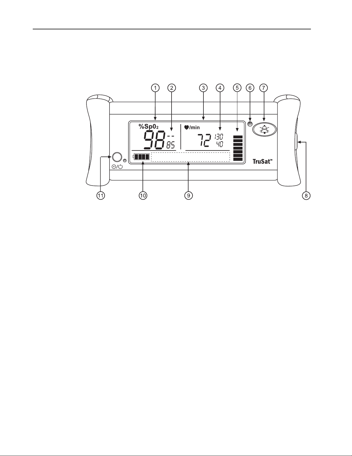
Screen display, controls, and indicators
NOTE: The monitor is shown without the handle.
Figure 1-1. Monitor features
1 Oxygen saturation (SpO2) measurement value
2 SpO2 high and low alarm limit settings, adjustable
3 Pulse rate measurement value
4 Pulse rate high and low alarm limit settings, adjustable
5 Plethysmographic pulse bar (pleth bar)
6 Alarm LED
7 Alarm Silence button
8 ComWheel navigation and selection knob for changing monitor settings
9 Display area for on-screen control symbols (set pulse beep volume, set alarm
volume, switch backlight ON/OFF, display PIr, print) and the lock symbol
10 Battery indicator
11 Power button and external power LED
Refer to the TruSat User’s Guide for detailed descriptions of all controls and
indicators.
1–2
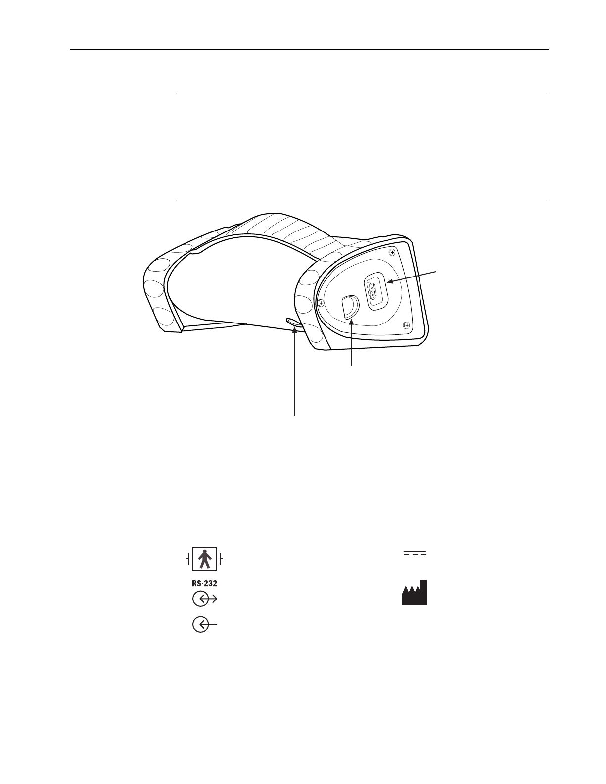
Connectors
Product Description and Specifications
WARNING: When you connect equipment to the monitor, you are
configuring a medical system and are responsible for ensuring that the
system complies with IEC 60601–1–1 and with local requirements. Connect
only external devices specified for use with the monitor.
WARNING: Use only sensors and cables authorized for use with this monitor.
Failure to do so may cause interference with the measurement or result in
increased emissions, decreased immunity, or damage to the equipment or
system.
Sensor connector
Connect an OxyTip+ sensor
or cable only.
Figure 1-2. Monitor connectors
Information label and symbols
A label on the underside of the monitor contains the model number, serial number,
date of manufacture, and other information about the monitor. The following
symbols also appear on this label and/or on the packaging for the monitor:
Sensor connector; defibrillationproof type BF applied part
RS-232 connector for the Trend
Download option
Power supply connector;
external power in
Trend Download connector (RS-232)
Connect the TruSat/PC RS-232 cable or the
TruSat/serial printer cable.
Power connector
Plug the power supply cable into this connector. Then, plug the
power cord into the power supply and into the AC power outlet.
DC current
Manufacturer
Other symbols on the monitor or the screen are described in the TruSat User’s Guide.
1–3

TruSat Technical Reference Manual
1.3 Safety precautions
Precautions associated with following safe practices while using the monitor appear
throughout this manual. General precautions are listed below. Carefully read all
precautions in this manual before repairing or using the monitor.
NOTE: For complete information about the safe and appropriate use of a sensor,
consult the instructions for that sensor.
Warnings
WARNINGS indicate potentially harmful situations that may cause injury to
a patient or operator.
• Do not use the monitor if the startup tones do not sound, the validity of data is
questionable, or if the monitor fails to function as described. Refer to the
appropriate sections of this manual to identify and correct the malfunction.
• Do not use the monitor in the presence of any flammable anesthetic mixture.
• Use only hospital-grade, grounded power outlets.
• Use only sensors and cables specified for use with this monitor. Failure to do so
may cause interference with the measurement or result in increased emissions,
decreased immunity, or damage to the equipment or system.
Cautions
• This monitor is not intended for use in a magnetic resonance imaging (MRI)
environment.
• When you connect equipment to the monitor, you are configuring a medical
system and are responsible for ensuring that the system complies with
IEC 60601–1–1 and with local requirements. Connect only external devices
specified for use with this monitor.
• Power OFF and disconnect the monitor from external power before performing
any procedure that involves disassembly of the monitor.
CAUTIONS indicate conditions that may lead to equipment damage or
malfunction.
• Internal electronic components are susceptible to damage by electrostatic
discharge. To avoid damage when disassembling the monitor, observe the
standard precautions and procedures for handling static-sensitive components.
• Do not store or use the monitor outside the temperature and humidity ranges
stated in the Specifications section of this manual.
• Never use a battery if its insulative wrap is ripped, torn, or has other visible
damage. A damaged battery wrap can cause internal shorting, overheating, or
other equipment damage.
1–4
Disposal
Recycle or dispose of this medical device, its components, and its packing materials
in accordance with local environmental and waste disposal regulations.

1.4 Specifications
Specifications are nominal and are subject to change without notice.
Factory settings
Setting Range Factory setting
High SpO2 alarm limit 51 to 100% or OFF (— —) OFF
Low SpO2 alarm limit 50 to 99% or OFF (— —) 85
High pulse rate alarm limit 30 to 235 bpm or OFF (— — —) 130
Low pulse rate alarm limit 30 to 235 bpm or OFF (— — —) 40
Backlight ON or OFF ON
Pulse beep volume 0 (OFF), 1, 2, 3, or 4 * 2
Alarm volume 1 (low), 2, 3, or 4 * 2
Line power filter 50 Hz or 60 Hz 60 Hz
* For more information, see Audio later in this section.
Product Description and Specifications
Measurement
General
Pulse oximetry sensors: OxyTip+ sensors only
Method: red and infrared light absorption
SpO
2
Calibrated for functional oxygen saturation
Calibration range: 70 to 100%
Measurement and display range: 1 to 100%
Display resolution: 1%
First reading, full accuracy: ≤ 10 seconds
Accuracy, A
SpO2 measurement accuracy is based on deep hypoxia studies using OxyTip+
sensors on volunteer subjects. Arterial blood samples were analyzed simultaneously
on multiple CO-oximeters.
NOTE: Accuracy may vary for some sensors; always check the instructions for the
sensor.
Red LED wavelength range: 650 to 670 nm
Infrared (IR) LED wavelength range: 930 to 950 nm
Average power: ≤ 1 mW
rms
(root mean square of paired values; previously represented by ± 1 SD):
70 to 100% ± 2 digits (without motion)
70 to 100% ± 3 digits (during clinical motion)
70 to 100% ± 2 digits (during clinical low perfusion)
Below 70% unspecified
1
1
Applicability: OxyTip+ Adult/Pediatric and AllFit sensors.
1–5

TruSat Technical Reference Manual
Pulse rate
Measurement and display range: 30 to 250 beats per minute (bpm)
Display resolution: 1 bpm
First reading, full accuracy: ≤ 15 seconds
Accuracy
30 to 250 bpm: ± 2 digits or ± 2%, whichever is greater (without motion)
30 to 250 bpm: ± 5 digits (during motion)
30 to 250 bpm: ± 3 digits (during low perfusion)
PIr pulsatile value
Measurement and display range: 0.01 to 9.99
Display resolution: 0.01 PI
Monitor
General
Lock function: locks/unlocks alarm limits and other settings
Factory calibrated; power-on self-test with calibration check
Recovery time after exposure to defibrillation voltage: ≤ 30 seconds
r
Display
Alarms
Liquid crystal display (LCD)
Backlight LED: ON or OFF
Plethysmographic pulse bar (pleth bar): ten-segment column; pulsates to indicate
pulse rate and signal strength
Display update time
SpO2, pulse rate, and PIr values: 1 second ± 0.25 second
Plethysmographic pulse bar: 20 Hz minimum (.05 second)
Visual and audible indicators for physiological alarms (SpO2 and pulse rate limit
alarms) and technical alarms (sensor condition, battery condition, internal
malfunction)
Visual alarm indicator, red/yellow LED
High priority alarm: red ON or red flashing ON/OFF
Medium priority alarm: yellow flashing ON/OFF
Visibility (operator positioned in front of monitor: 4 m (13 ft.) at 30° angle in any
direction
NOTE: When an SpO2 or pulse rate alarm limit is violated, the related
measurement flashes ON/OFF.
Audible alarm indicator: pattern varies according to alarm type and priority
Alarm Silence button: silences alarms for 2 minutes (press once; screen symbol is
displayed) or indefinitely (press 3 times; screen symbol flashes ON/OFF)
NOTE: If an alarm condition is not present, the alarm LED is lit yellow to indicate
future alarms will be silenced.
1–6

Audio
Pulse rate beep: tone rises as oxygen saturation increases and falls as it decreases
Adjustable alarm volume and pulse beep volume: 4-segment on-screen controls
Volume intensity at distance of 1 m (3.28 ft.): 45 dB minimum to 85 dB maximum
External power
Power supply (AC to DC converter)
AC power input: 100–240 V, 0.5 A, 50–60 Hz
Power supply (DC to DC)
DC power input from vehicle cigarette lighter: 12 V
Power supply output to monitor: 12 VDC, 1.25 A, 15 watt
Power indicator (green LED): ON while monitor is connected to external power
Line power filter (monitor setting): 50 Hz or 60 Hz
Internal battery power
Type: Internal, rechargeable, nickel metal hydride (NiMH), 3 AH, 12 VDC, 150 mA
Self-discharge when stored at room temperature (typical for all NiMH batteries):
at least 30% of a full charge remains after 3 months of storage
Capacity, fully charged, operating at room temperature:
Without Trend Download option: 35 hours
With Trend Download option: 24 hours
NOTE: Continuous use of the backlight reduces the time approximately 50%.
Charging time (full capacity): 3.5 hours typical
Battery indicator: 4-segment symbol; shaded segments represent battery charge
(0 shaded = low or depleted; 4 shaded = fully charged)
Automatic power OFF to conserve battery: 20 minutes after monitoring stops
Product Description and Specifications
Trend Download option
Trend data storage: 48 hours with a data storage resolution of 1 data point every
4 seconds
RS-232 serial port: DIN 6 circular connector
19.2K baud, 8 data bits, 1 start bit, 1 stop bit
Handshaking (RTS, CTS), full duplex, no parity
Environmental conditions
NOTE: To maximize battery life, store the monitor at room temperature.
Temperature 10 to 40 ºC
Relative humidity,
noncondensing
Atmospheric pressure 1060 to 697 hPa 1060 to 188 hPa
Approximate elevation –378 to 3048 m
Dimensions and weight
Width/Depth/Height including handle = 21.8 x 11.5 x 10.3 cm (8.5 x 4.5 x 4 inches)
Weight = 1.25 kg (2.76 pounds)
1.47 kg (3.26 pounds) with Trend Download option
Operating Transport and Storage
–40 to 70 ºC
(50 to 104 ºF)
20 to 95% 5 to 95%
(–1240 to 10,000 ft.)
(–40 to 158 ºF)
–378 m to 12.2 km
(–1240 to 40,000 ft.)
1–7

TruSat Technical Reference Manual
1.5 Compliance
European Union Medical Device Directive 93/42/EEC: Class IIb
EN 60601-1 Medical electrical equipment – Part 1: General requirements for safety
(including Amendments 1 and 2)
• Type of protection against electric shock: Class I equipment/Internal electrical
power source
• Degree of protection against electric shock: Defibrillation-proof type BF applied
part
• Degree of protection against ingress of water (EN 60529): IPX2
• Not suitable for use in the presence of flammable anesthetic mixtures
• Mode of operation: Continuous
EN 60601-1-2 (2nd Edition) Electromagnetic compatibility – Requirements and tests For
details, see Electromagnetic compatibility (EMC) later in this section.
CISPR 11/EN 55011 (Protection against emissions): Group I, Class B
IEC 60601-1-8 Alarm systems – General requirements, tests and guidance for alarm
systems in medical electrical equipment and systems
Medical electrical equipment classified in the US and Canada with respect
to electric shock, fire, and mechanical hazards only, in accordance with
the Canadian Standards Association CAN/CSA C22.2 No. 601.1 and
Underwriters Laboratories Inc. UL 2601–1.
Related standards and tests
Standard Description
EN 60601-1, clause 21 Rigidity, strength, handle loading drop test
EN 60601-1, clause 42 Temperature
EN 60601-1, clause 48 Non-toxic materials used for surface of case
EN 60601-1, sub-clause 59.2(b) Resistance of case to heat and fire
EN 865, clause 44 Overflow, spillage, ingress of liquids, cleaning
IEC 61000-3-2 Harmonic emissions
IEC 61000-3-3 Voltage fluctuations and flicker emissions
IEC 61000-4-2, level 3 Electrostatic discharge immunity
IEC 61000-4-3, level 2 Radiated RF electromagnetic field immunity
IEC 61000-4-4, level 3 Electrical fast transient and burst immunity
IEC 61000-4-5, level 3 Surge immunity
IEC 61000-4-6 Susceptibility to conducted EMI
IEC 61000-4-8 Power frequency magnetic fields
IEC 61000-4-11, Table 7 Operation during line voltage variations
IEC 60068-2-32 Operation during physical shock/drop and
UL 2601-1, clause 55 Impact test
and disinfection
repetitive drop
1–8
Product Description and Specifications
Electromagnetic compatibility (EMC)
When using this monitor, take precautions to ensure electromagnetic compatibility.
Indications that the monitor is experiencing electromagnetic interference include,
for example, a dashed display or sudden changes in the pleth bar height that do not
correlate to the physiological condition of the patient. This interference may be
intermittent and careful correlation between the effect and its possible source is
important. Indications of interference should not occur if the monitor is used within
its intended electromagnetic environment.
Electromagnetic interference, including interference from portable and mobile radio
frequency (RF) communications equipment, can affect this monitor. When using the
monitor, take precautions to ensure electromagnetic compatibility.
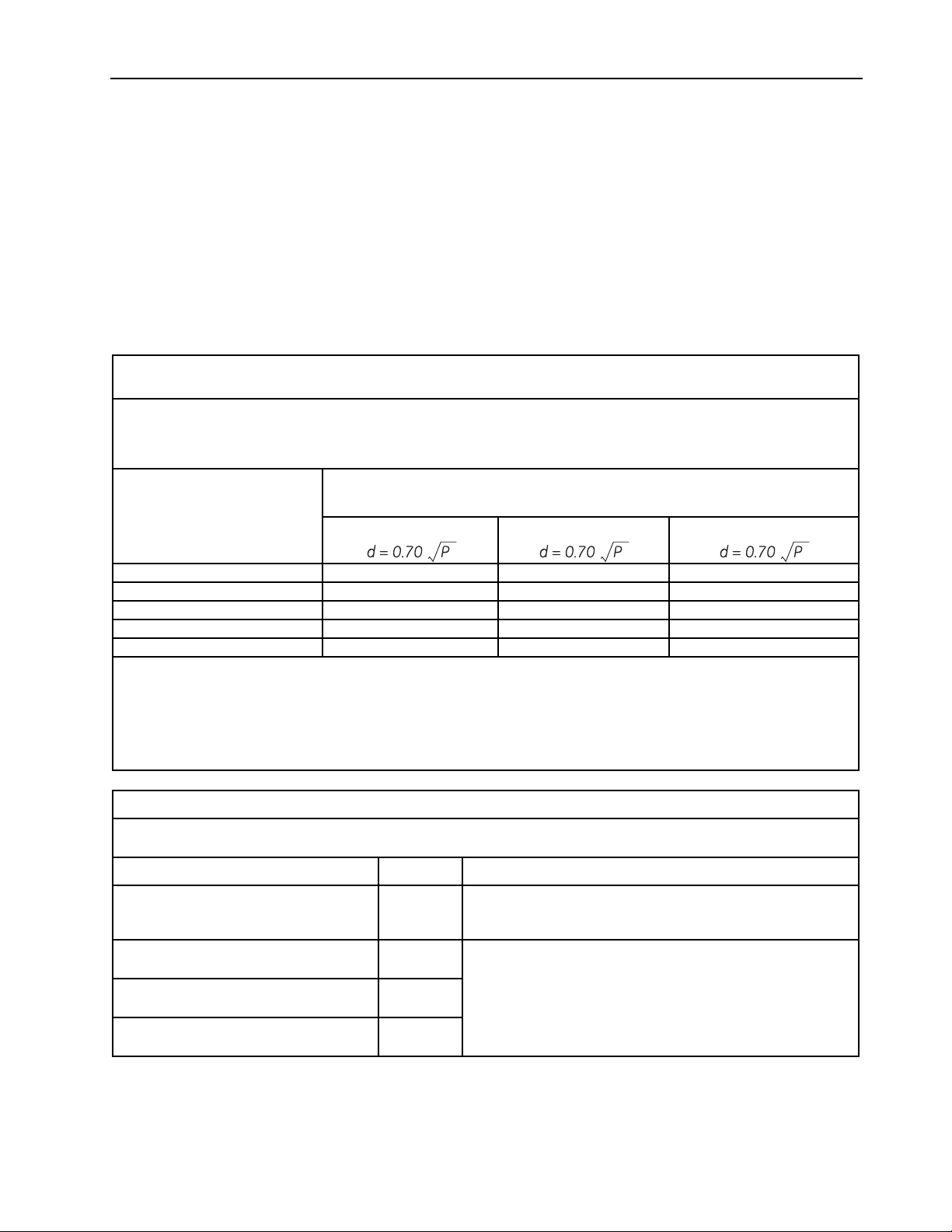
Recommended Separation Distances between
Portable and Mobile RF Communications Equipment and the TruSat
The TruSat pulse oximeter is intended for use in an electromagnetic environment in which RF disturbances are
controlled. The customer or the user of the monitor can prevent electromagnetic interference by maintaining a
minimum distance between portable and mobile RF communications equipment (transmitters) and the monitor as
recommended below, according to the maximum output power of the communications equipment.
Separation distance according to the frequency of the transmitter
Rated maximum output
power of the transmitter
W
150 kHz to 80 MHz
80 MHz to 800 MHz 800 MHz to 2,5 GHz
m
0.01 0.07 0.07 0.07
0.1 0.22 0.22 0.22
1 0.70 0.70 0.70
10 2.2 2.2 2.2
100 7.0 7.0 7.0
For transmitters rated at a maximum output power not listed above, the recommended separation distance d in
meters (m) can be estimated using the equation applicable to the frequency of the transmitter, where P is the
maximum output power rating of the transmitter in watts (W) according to the transmitter manufacturer.
NOTE 1: At 80 MHz and 800 MHz, the separation distance for the higher frequency range applies.
NOTE 2: These guidelines may not apply in all situations. Electromagnetic propagation is affected by absorption
and reflection from structures, objects, and people.
Guidance and manufacturer’s declaration - electromagnetic emissions
The TruSat pulse oximeter is suitable for use in the electromagnetic environment specified below. The customer or the
user of the monitor should assure that it is used in such an environment.
Emissions test Compliance Electromagnetic environment - guidance
RF emissions
CISPR 11
RF emissions
CISPR 11
Harmonic emissions
IEC 61000-3-2
Voltage fluctuations/flicker emissions
IEC 61000-3-3
Group 1
Class B
Class A
Complies
The TruSat uses RF energy only for its internal function.
Therefore, its RF emissions are very low and are not likely to
cause any interference in nearby electronic equipment.
The TruSat is suitable for use in all establishments, including
domestic establish ments and those directly connected to
the public low-voltage power supply network that supplies
buildings used for domestic purposes.
1–9

TruSat Technical Reference Manual
Guidance and manufacturer’s declaration - electromagnetic immunity
The TruSat pulse oximeter is intended for use in the electromagnetic environment specified below. The customer or
the user of the monitor should assure that it is used in such an environment.
Immunity test EN 60601-1-2 test level Compliance level
Electrostatic
discharge (ESD)
± 6 kV contact
± 8 kV air
± 6 kV contact
± 8 kV air
IEC 61000-4-2
Electrical fast
transient/burst
± 2 kV for power supply lines
± 1 kV for input/output lines
± 2 kV for power supply lines
± 1 kV for input/output lines
IEC 61000-4-4
Surge
IEC 61000-4-5
Voltage dips,
short
interruptions
and voltage
variations on
power supply
input lines
IEC 61000-4-11
Power frequency
± 1 kV differential mode
± 2 kV common mode
< 5 % U
T
(> 95 % dip in UT) for 0,5 cycle
40 % U
T
(60 % dip in UT) for 5 cycles
70 % U
T
(30 % dip in UT) for 25 cycles
< 5 % U
T
(> 95 % dip in UT) for 5 sec.
± 1 kV differential mode
± 2 kV common mode
< 5 % U
T
(> 95 % dip in UT) for 0,5 cycle
40 % U
T
(60 % dip in UT) for 5 cycles
70 % U
T
(30 % dip in UT) for 25 cycles
< 5 % U
T
(> 95 % dip in UT) for 5 sec.
10 A/m 3 A/m Power frequency magnetic
(50/60 Hz)
magnetic field
IEC 61000-4-8
NOTE: UT is the AC mains voltage prior to application of the test level.
Electromagnetic environment -
guidance
Floors should be wood,
concrete, or ceramic tile. If
floors are covered with
synthetic material, the relative
humidity should be at least
30%.
Mains power quality should be
that of a typical commercial
or hospital environment
Mains power quality should be
that of a typical commercial
or hospital environment.
Mains power quality should be
that of a typical commercial
or hospital environment. If the
user requires continued
operation during power mains
interruptions, it is
recommended that the TruSat
be powered from an
uninterruptible power supply
or a battery.
fields should be at levels
characteristic of a typ i cal
location in a typical
commercial or hospital
environment.
1–10
 Loading...