


IC695PNS001
Table of contents
 Loading...
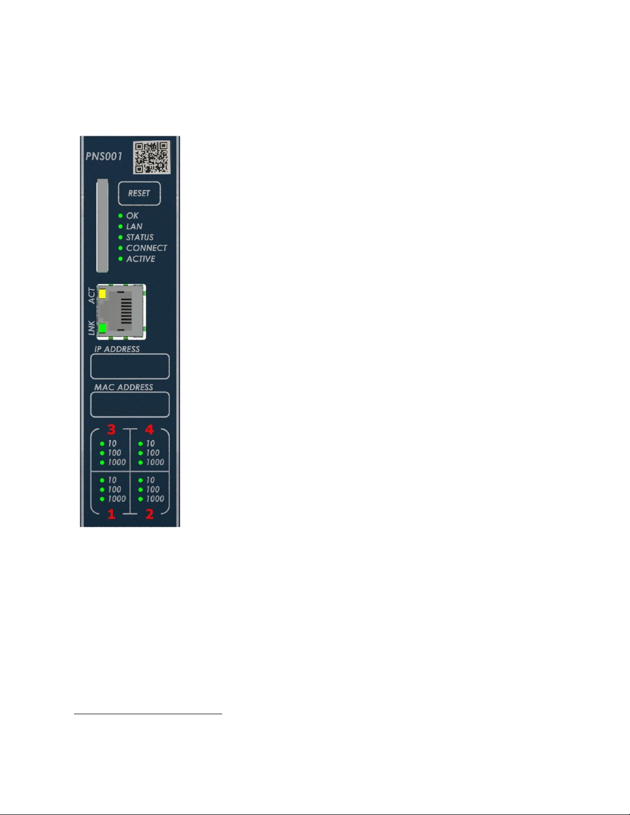
Important Product Information PACSystems* RX3i
IC695PNS001-BBBC IC695PNS101-AAAA
IC695PNS001CA-BBBC IC695PNS101CA-AAAA
GFK-2738Q RX3i PROFINET Scanner RX3i Advanced PROFINET Scanner
August 2018
The PACSystems* IC695PNS001 RX3i PROFINET Scanner and IC695PNS101 RX3i Advanced
PROFINET Scanner modules connect a remote universal RX3i I/O rack of Series 90-30 or
RX3i modules to a PROFINET I/O Controller. The PROFINET Scanner scans the modules in
its rack, retrieving input data and providing output data, and exchanges that data on the
PROFINET I/O LAN at the configured production rate.
The PNS manages PROFINET communication and module configuration between an I/O
Controller and modules in the remote rack. If network communications are lost, the PNS
manages I/O states according to the individual module configurations.
The PNS001 and PNS101 support 10/100/1000 Mbps Copper, 100/1000 Mbps Multimode Fiber, and 100/1000 Mbps Single-mode Fiber. PROFINET communications on the
network require 100 or 1000 Mbps link speed. Although 10 Mbps cannot be used for
PROFINET communications, 10 Mbps can be used for other types of Ethernet traffic such
as PING.
Features of the RX3i PNS001 PROFINET Scanner include:
▪ Configuration services for all supported Series 90-30 and RX3i I/O Modules using
Proficy* Machine Edition (PME). For a list of currently supported I/O modules, refer
to Supported Modules, Power Supplies and Backplanes.
▪ Support for daisy-chain/line, star, or ring (PROFINET Media Redundancy Protocol
(MRP)) topologies.
▪ Four switched Ethernet ports - two 8-conductor RJ-45 shielded twisted pair
10/100/1000 Mbps copper interfaces and two Small Form-factor Pluggable (SFP)
cages for user-supplied SFP devices.
▪ The network can include media interfaces of more than one type.
▪ Support for transfer of I/O Device Name to another PNS module using an SD card.
This eliminates the need to connect a configuration tool, such as Proficy Machine
Edition when replacing a module.
▪ A front panel Ethernet RJ-45 port for field firmware updates.
The RX3i PNS101 Advanced PROFINET Scanner includes all features of the
PNS001 PROFINET Scanner and adds:
▪ Support for Sequence of Events recording with IRIG-B time synchronization of events
accurate to 1ms. The PNS101 buffers up to 4000 events from up to four
IC694MDL660 32 Circuit Discrete Input modules at a maximum rate of 400 events
per second. Unmodulated IRIG B time signals are decoded using either an
IC695HSC304 or IC695HSC308 High Speed Counter Module. The PNS101 may also be
used as a standard PROFINET scanner when Sequence of Events is disabled.
*
Indicates a trademark of General Electric Company and/or its subsidiaries. All other trademarks are the property of their respective
owners.
© 2013-2018 General Electric Company. All Rights Reserved.
The PNS001 & PNS101
share the same front
panel markings except
for the catalog
number and QR code.

2 RX3i PROFINET Scanner & Advanced PROFINET Scanner
GFK-2738Q IC695PNS001-BBBC & IC695PNS101-AAAA
Ordering Information
IC695PNS001
PACSystems RX3i PROFINET Scanner Module 10/100/1000 with four Ports
(two SFP connections, two RJ45 connections)
Includes a blank SD card
IC695PNS001CA
Conformal Coated PACSystems RX3i PROFINET Scanner Module 10/100/1000 with four Ports
(two SFP connections, two RJ45 connections)
Includes a blank SD card
IC695PNS101
PACSystems RX3i Advanced PROFINET Scanner Module 10/100/1000 with four Ports
(two SFP connections, two RJ45 connections)
Includes a blank SD card
IC695PNS101CA
Conformal Coated PACSystems RX3i Advanced PROFINET Scanner Module 10/100/1000 with four Ports
(two SFP connections, two RJ45 connections)
Includes a blank SD card
IC695SPC100
RX3i 10/100/1000Base-T copper SFP
IC695SPF002
RX3i 100Base-FX (fiber 2 km) SFP (Multi-mode fiber - MMF)
IC695SPF550
RX3i 1000Base-SX (fiber 550 m) SFP (MMF)
IC695SPF010
RX3i 1000Base-LX (fiber 10 km) SFP (Single-mode fiber - SMF)

RX3i PROFINET Scanner & Advanced PROFINET Scanner 3
IC695PNS001-BBBC & IC695PNS101-AAAA GFK-2738Q
Specifications
PROFINET Support
PROFINET Version 2.3 Class A I/O Device
Redundantly controlled operation implements PROFINET V2.3 Type S-2 System Redundancy
Proficy Machine Edition
Version Required
PNS001 & PNS101: Version 8.50 SIM 2 or later
Power Requirements
PNS001-Bxxx or later:
PNS101-Axxx or later:
3.3 Vdc
0.6 A with no SFP devices installed
1.3 A maximum (two SFP devices installed,
0.35A per SFP)
PNS001-Axxx:
3.3 Vdc
1.2 A with no SFP devices installed
1.9 A maximum (two SFP devices installed,
0.35A per SFP)
PNS001-Bxxx or later:
PNS101-Axxx or later:
5Vdc: 0.7 A maximum
PNS001-Axxx:
5Vdc: 1.1 A maximum
Operating Temperature
Range
PNS001-Bxxx or later:
PNS101-Axxx or later:
-25°C to 60°C
Derated to 57°C:
• If 100MB Fiber SFPs installed, or
• If Copper SFPs operating at 1GB
PNS001-Axxx:
0°C to 60°C
Derated to 57°C:
• If 100MB Fiber SFPs installed, or
• If Copper SFPs operating at 1GB
Number of Port Connectors
Two RJ-45 and Two SFP Cages (SFP devices not included, available separately)
FW Upgrade Connector
PNS001-Bxxx & PNS101-Axxx:
One RJ-45 Ethernet connector on front panel
PNS001-Axxx:
One USB connector on front panel
SD Card
Supports SD and SDHC cards.
PNS001 Status and Control
Bits
32 input status bits and 32 output control bits
PROFINET I/O production
rate (I/O Update Rate)
Configurable selections: 1ms, 2ms, 4ms, 8ms, 16ms, 32ms, 64ms, 128ms, 256ms or 512ms
Number of IP addresses
PNS001-Bxxx & PNS101-Axxx: Two
One for PROFINET ports.
One for front panel port. Supports Classless
Inter-Domain Routing (CIDR)
PNS001-Axxx: One
One for PROFINET ports.
Number of MAC Addresses
PNS001-Bxxx & PNS101-Axxx: Six
One front panel port, one for each of the four
external ports, and one internal port.
PNS001-Axxx: Five
One for each of the four external ports, and
one internal port.
I/O Station Maximum Limits
Number of I/O Modules per station
Number of backplane slots minus one for the
PNS and at least one for a power supply
I/O data per station
2880 bytes total
1440 bytes of input data
1440 bytes of output data
Configuration
V2.3 GSDML file is available on the Support website http://support.ge-ip.com for download and
import into Proficy Machine Edition. The GSDML supporting a firmware release is part of the
firmware upgrade kit available on the Support website.
For installation and maintenance requirements, refer to PACSystems RX3i/Series 90-30 Installation and Maintenance
Requirements, GFK-2975.

4 RX3i PROFINET Scanner & Advanced PROFINET Scanner
GFK-2738Q IC695PNS001-BBBC & IC695PNS101-AAAA
PROFINET Scanner Status and Control Data
The RX3i PROFINET Scanner provides 32 bits of input status data and receives 32 bits of output control data. The
application program in the I/O Controller system can monitor the input status bits for the PNS module. The output
control bits are reserved for future use and have no function at this time.
Output Control Bits:
PNS001 -Axxx hardware: The 32 bits of control output assigned to the PNS module are reserved for future use.
PNS001-Bxxx or later and PNS101-Axxx hardware: The 32-bits of control output assigned to the PNS module allow the
IO Controller to dynamically control aspects of the scanner’s operation. All control bits are active high. Bit 1 is the least
significant bit.
Bit #
Name
Description
1
FW Update in
Run
A value of 1 allows the webpage firmware update to continue (and restart the PNS
disrupting IO) while the PNS IO is actively controlled.
2–32
Reserved
Set to 0
Input Status Bits:
The PROFINET Scanner’s 32 bits of input status provide information about the scanner. All status bits are active high.
Bit 1 is the least significant bit.
Status
Bits
Name
Description
1
Module OK
Indicates the health of the module. A value of 0 indicates the module is powering up
or has failed. A value of 1 indicates the module is functioning properly.
2
Reserved
Set to 0
3
Port1 Link Up
1 = port is connected to another device and is communicating.
0 = port is not connected to another device, or the port has some sort of error
preventing communications.
4
Port2 Link Up
5
Port3 Link Up
6
Port4 Link Up
7-10
Reserved
Set to 0
11
MRP Enabled
Indicates whether MRP has been enabled or not. A value of 0 indicates that MRP is
not enabled. A value of 1 indicates that MRP is enabled.
12
MRP Role
Indicates the MRP role the PNS is operating as when MRP is enabled. A value of 0
indicates that the PNS is currently an MRP Client. A value of 1 indicates that the PNS
is currently an MRP Manager, however the PNS does not currently support MRP
Manager configuration. If MRP is not enabled, then this bit will be set to zero.
13
Clock Sync’d
PNS101: The internal clock has been sync’d to the IRIG-B clock source. This bit may
take up to 90 seconds to turn on after the IRIG-B clock is available.
PNS001: Set to 0
14
SoEs Avail
PNS101: SoE Records are available for upload.
PNS001: Set to 0
15-32
Reserved
Set to 0
RX3i PROFINET Scanner & Advanced PROFINET Scanner 5
IC695PNS001-BBBC & IC695PNS101-AAAA GFK-2738Q
LEDs on the PROFINET Scanner Module
Power-Up LED Patterns
At power-up, the LEDs show the patterns described in the following table. The LEDs also blink diagnostic patterns for
certain operating errors and for module identification.
Step
LED/ Blink pattern
Description
1
All LEDs off
Initial state
2
ACTIVE LED solid green
Normal operation
3
CONNECT LED solid green
Normal operation
4
STATUS LED solid green
Normal operation
5
LAN LED solid green
Normal operation
OK LED blinks amber with
special blink code
Fatal initialization or diagnostics failure;
H/W Module Identity Information not
available
STATUS LED blinks amber with
special blink code
Fatal initialization failure.
STATUS and LAN LEDs blink
green in unison (0.5 seconds
ON/ 0.5 seconds OFF)
Internal update in process following a
firmware update. Unit should complete
update and restart automatically.
6
OK LED solid green
Normal operation. Power-up completed.
Note: Under certain ambient operating temperatures, the PROFINET Scanner could
momentarily display the over temperature pattern during power up, while it is
calibrating its thermal protection functions. This indication can be ignored. For details,
refer to the section entitled Microprocessor Over-Temperature in PACSystems RX3i
PROFINET Scanner Manual, GFK-2737.
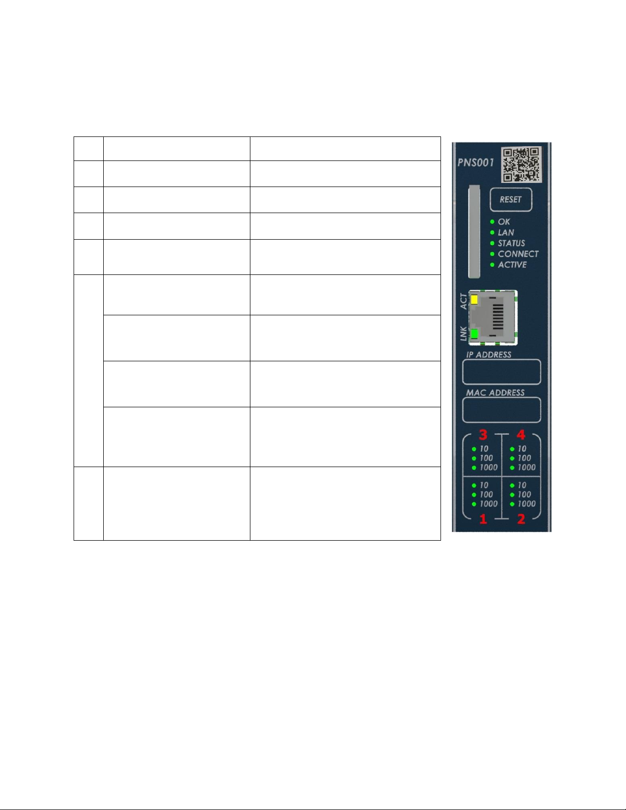
The PNS001 & PNS101
share the same front
panel markings except
for the catalog
number and QR code.
6 RX3i PROFINET Scanner & Advanced PROFINET Scanner
GFK-2738Q IC695PNS001-BBBC & IC695PNS101-AAAA
Normal Operation of Individual LEDs
The PNS’s LEDs can operate in tandem to indicate fatal error, module location/identification, microprocessor overtemperature, and update conditions. For details on these blink patterns, refer to PACSystems RX3i PROFINET Scanner
Manual, GFK-2737.
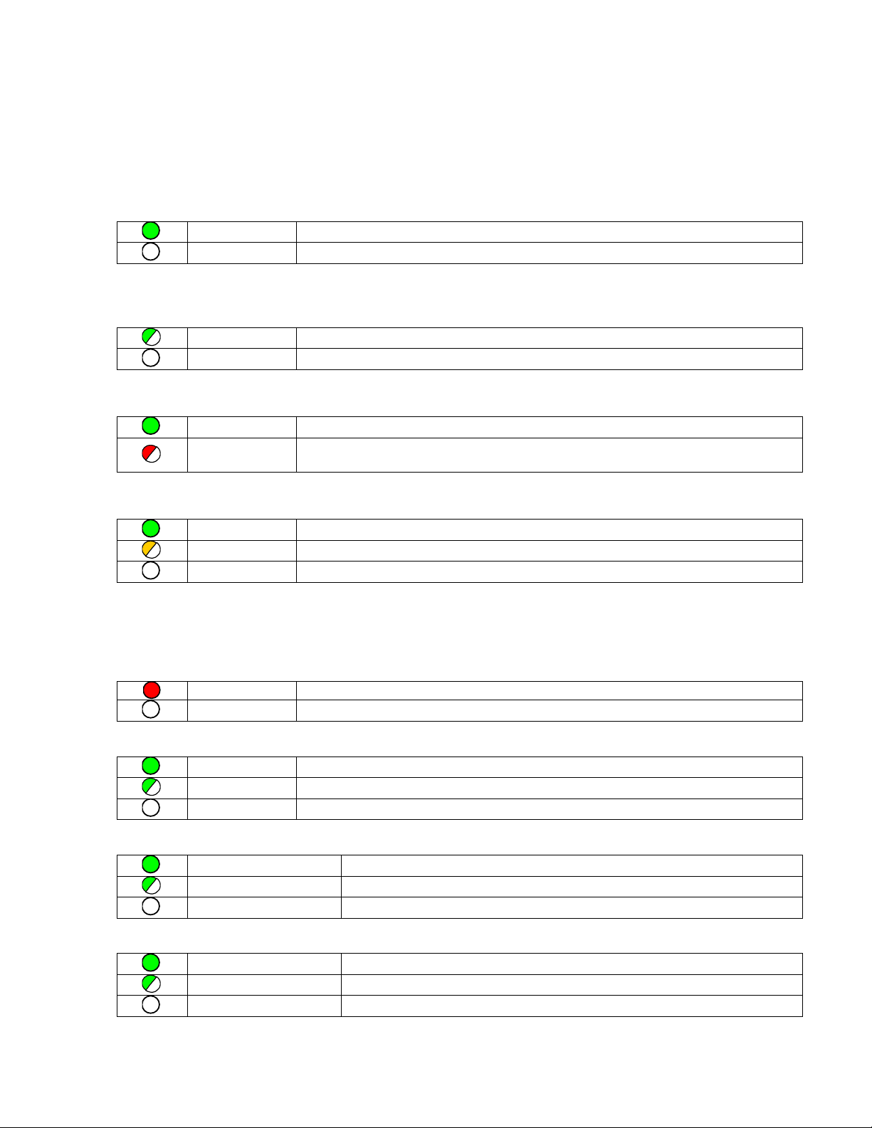
OK LED
The OK LED indicates whether the module is able to perform normal operation.
Green, on
OK
Off
Not OK
LAN LED
The LAN LED indicates access to and activity on the PROFINET network. The LAN LED indicates network packets are
being processed by the network interface (not just passing through the embedded switch).
Blinking on
The module’s network interface is active
Off
No activity
STATUS LED
The STATUS stays Green during normal operation.
Green, on
Normal Operation
Red, blinking
A MAC address read from nonvolatile memory is invalid. Ports with invalid MAC addresses
remain disconnected from the Ethernet network.
CONNECT LED (CONN on -AXXX versions)
The CONN LED indicates the status of PROFINET connections.
Green, on
At least one PROFINET connection (AR) exists with an I/O Controller.
Amber, blinking
No device name configured.
Off
No PROFINET connection (AR) exists.
Port LEDs
The PROFINET Scanner has four LEDs that indicate link speed, link connection and link activity corresponding to the
four possible external Ethernet ports.
Port Number LED
Red, on
Port 3 and 4 only: Error such as incompatible SFP.
Off
No Port error.
1000 Speed LED
Green on
Link connected, 1000 Mbps
Green blinking
Port active, 1000 Mbps
Off
The associated Ethernet port is not connected to an active link at 1000Mbps
100 Speed LED
Green, on
Link connected, 100 Mbps.
Green, blinking
Port active, 100 Mbps
Off
The associated Ethernet port is not connected to an active link at 100Mbps
10 Speed LED
Green, on
Link connected, 10 Mbps.
Green, blinking
Port active, 10 Mbps
Off
The associated Ethernet port is not connected to an active link at 10Mbps
Loading...