

Page 1
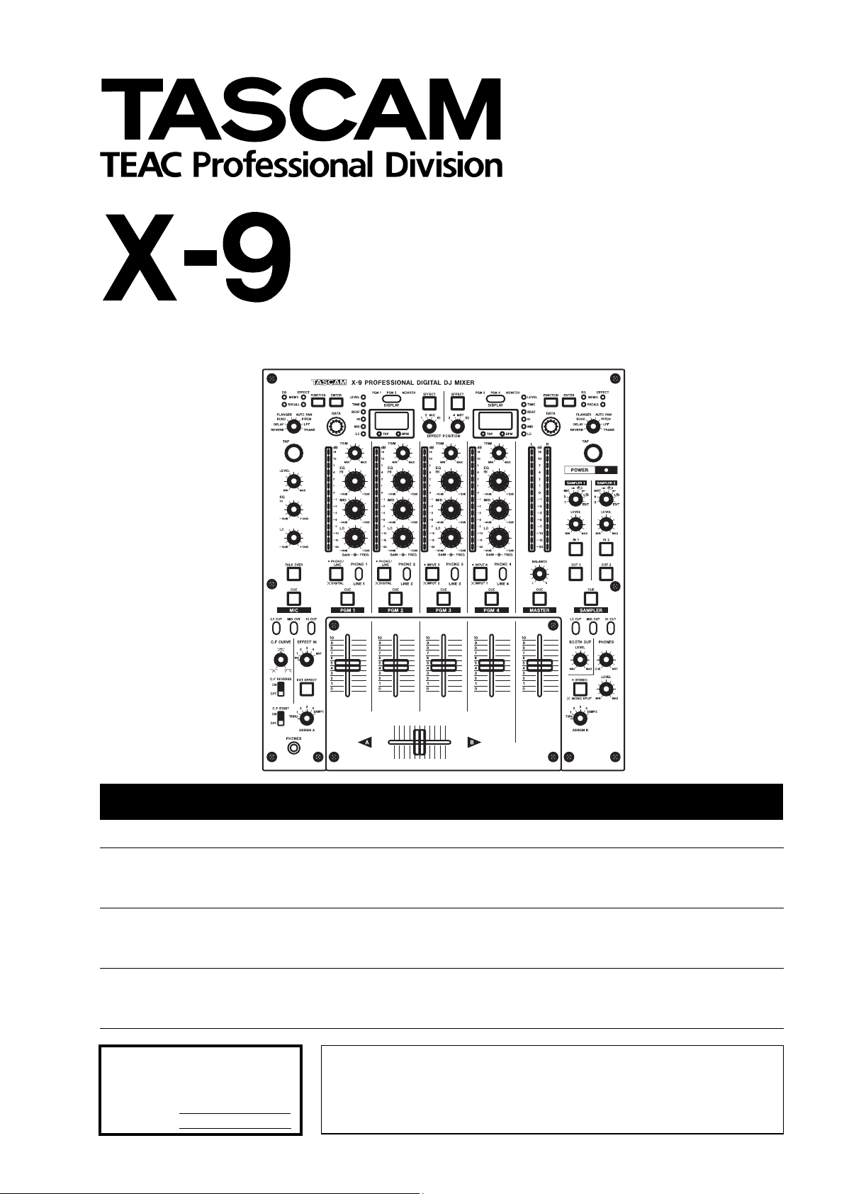
Professional Digital DJ Mixer
9101441900
OWNER’S MANUAL
Ü
The lightning flash with arrowhead symbol, within an equilateral triangle, is intended to alert
ÿ
Ÿ
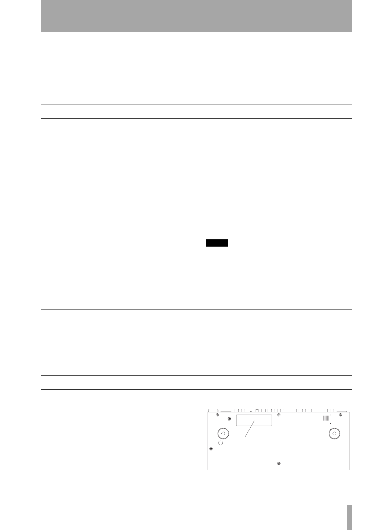
This appliance has a serial number
located on the bottom. Please record
the model number and serial number
and retain them for your records.
Model number
Serial number
the user to the presence of uninsulated “dangerous voltage” within the product’s enclosure
that may be of sufficient magnitude to constitute a risk of electric shock to persons.
The exclamation point within an equilateral triangle is intended to alert the user to the presence of important operating and maintenance (servicing) instructions in the literature
accompanying the appliance.
CAUTION: TO REDUCE THE RISK OF ELECTRIC SHOCK, DO NOT
REMOVE COVER (OR BACK). NO USER-SERVICEABLE PARTS
INSIDE. REFER SERVICING TO QUALIFIED SERVICE PERSONNEL.
WARNING: TO PREVENT FIRE OR SHOCK
HAZARD, DO NOT EXPOSE THIS
APPLIANCE TO RAIN OR MOISTURE.
Page 2

Important Safety Precautions
IMPORTANT (for U.K. Customers)
DO NOT cut off the mains plug from this equipment.
If the plug fitted is not suitable for the power points in your home or
the cable is too short to reach a power point, then obtain an
appropriate safety approved extension lead or consult your dealer.
If nonetheless the mains plug is cut off, remove the fuse
of the plug immediately, to avoid a possible shock hazard by
inadvertent connection to the mains supply.
If this product is not provided with a mains plug, or one has to be
fitted, then follow the instructions given below:
IMPORTANT: DO NOT make any connection to the larger
terminal which is marked by the letter E or by the safety earth
symbol ç
The wires in this mains lead are coloured in accordance with the
following code:
As the colours of the wires in the mains lead of this apparatus may
not correspond with the coloured markings identifying the terminals
in your plug proceed as follows:
or coloured GREEN or GREEN-and-YELLOW.
BLUE : NEUTRAL
BROWN : LIVE
and dispose
For U.S.A
TO THE USER
This equipment has been tested and found to
comply with the limits for a Class A digital device,
pursuant to Part 15 of the FCC Rules. These
limits are designed to provide reasonable
protection against harmful interference when the
equipment is operated in a commercial
environment. This equipment generates, uses,
and can radiate radio frequency energy and, if
not installed and used in accordance with the
instruction manual, may cause harmful
interference to radio communications.
Operation of this equipment in a residental area
is likely to cause harmful interference in which
case the user will be required to correct the
interference at his own expense.
CAUTION
Changes or modifications to this equipment not
expressly approved by TEAC CORPORATION
for compliance could void the user’s authority to
operate this equipment.
The wire which is coloured BLUE must be connected to the terminal
which is marked with the letter N or coloured BLACK.
The wire which is coloured BROWN must be connected to the
terminal which is marked with the letter L or coloured RED.
When replacing the fuse only a correctly rated approved type should
be used and be sure to re-fit the fuse cover.
IF IN DOUBT — CONSULT A COMPETENT ELECTRICIAN.
For the consumers in Europe
WARNING
This is a Class A product. In a domestic environment, this
product may cause radio interference in which case the user
may be required to take adequate measures.
Pour les utilisateurs en Europe
AVERTISSEMENT
Il s’agit d’un produit de Classe A. Dans un environnement
domestique, cet appareil peut provoquer des interférences
radio, dans ce cas l’utilisateur peut être amené à prendre
des mesures appropriées.
Für Kunden in Europa
Warnung
Dies is eine Einrichtung, welche die Funk-Entstörung nach
Klasse A besitzt. Diese Einrichtung kann im Wohnbereich
Funkstörungen versursachen ; in diesem Fall kann vom
Betrieber verlang werden, angemessene Maßnahmen
durchzuführen und dafür aufzukommen.
The equipment draws nominal non-operating power from the
AC outlet with its POWER switch in the off position.
2 TASCAM X-9 Owner’s Manual
Page 3
IMPORTANT SAFETY INSTRUCTIONS
CAUTION:
…Read all of these Instructions.
…Save these Instructions for later use.
…Follow all Warnings and Instructions marked on the audio
equipment.
1) Read Instructions — All the safety and operating instructions should
be read before the product is operated.
2) Retain Instructions — The safety and operating instructions should
be retained for future reference.
3) Heed Warnings — All warnings on the product and in the operating
instructions should be adhered to.
4) Follow Instructions — All operating and use instructions should be
followed.
5) Cleaning — Unplug this product from the wall outlet before cleaning.
Do not use liquid cleaners or aerosol cleaners. Use a damp cloth for cleaning.
6) Attachments — Do not use attachments not recommended by the
product manufacturer as they may cause hazards.
7) Water and Moisture — Do not use this product near water — for
example, near a bath tub, wash bowl, kitchen sink, or laundry tub; in a wet
basement; or near a swimming pool; and the like.
8) Accessories — Do not place this product on an unstable cart, stand,
tripod, bracket, or table. The product may fall, causing serious injury to a
child or adult, and serious damage to the product. Use only with a cart,
stand, tripod, bracket, or table recommended by the manufacturer, or sold
with the product. Any mounting of the product should follow the manufacturer’s instructions, and should use a mounting accessory recommended by
the manufacturer.
9) A product and cart combination should be moved with care. Quick stops,
excessive force, and uneven surfaces may cause the product and cart combination to overturn.
10) Ventilation — Slots and openings in the cabinet are provided for ventilation and to ensure reliable operation of the product and to protect it from
overheating, and these openings must not be blocked or covered. The openings should never be blocked by placing the product on a bed, sofa, rug, or
other similar surface. This product should not be placed in a built-in installation such as a bookcase or rack unless proper ventilation is provided or
the manufacturer’s instructions have been adhered to.
11) Power Sources — This product should be operated only from the
type of power source indicated on the marking label. If you are not sure of
the type of power supply to your home, consult your product dealer or local
power company. For products intended to operate from battery power, or
other sources, refer to the operating instructions.
12) Grounding or Polarization — This product may be equipped with a
polarized alternating-current line plug (a plug having one blade wider than
the other). This plug will fit into the power outlet only one way. This is a
safety feature. If you are unable to insert the plug fully into the outlet, try
reversing the plug. If the plug should still fail to fit, contact your electrician
to replace your obsolete outlet. Do not defeat the safety purpose of the
polarized plug.
13) Power-Cord Protection — Power-supply cords should be routed so
that they are not likely to be walked on or pinched by items placed upon or
against them, paying particular attention to cords at plugs, convenience
receptacles, and the point where they exit from the product.
14) Outdoor Antenna Grounding — If an outside antenna or cable
system is connected to the product, be sure the antenna or cable system is
grounded so as to provide some protection against voltage surges and builtup static charges. Article 810 of the National Electrical Code, ANSI/NFPA
70, provides information with regard to proper grounding of the mast and
supporting structure, grounding of the lead-in wire to an antenna discharge
unit, size of grounding conductors, location of antenna-discharge unit, connection to grounding electrodes, and requirements for the grounding electrode.
"Note to CATV system installer:
This reminder is provided to call the CATV system installer’s attention to
Section 820-40 of the NEC which provides guidelines for proper grounding
and, in particular, specifies that the cable ground shall be connected to the
grounding system of the building, as close to the point of cable entry as
practical.
Example of Antenna Grounding as per
National Electrical Code, ANSI/NFPA 70
ANTENNA
LEAD IN
WIRE
GROUND
CLAMP
ANTENNA
DISCHARGE UNIT
(NEC SECTION 810-20)
ELECTRIC
SERVICE
EQUIPMENT
NEC - NATIONAL ELECTRICAL CODE
GROUNDING CONDUCTORS
(NEC SECTION 810-21)
GROUND CLAMPS
POWER SERVICE GROUNDING
ELECTRODE SYSTEM
(NEC ART 250. PART H)
15) Lightning — For added protection for this product during a lightning
storm, or when it is left unattended and unused for long periods of time,
unplug it from the wall outlet and disconnect the antenna or cable system.
This will prevent damage to the product due to lightning and power-line
surges.
16) Power Lines — An outside antenna system should not be located in
the vicinity of overhead power lines or other electric light or power circuits,
or where it can fall into such power lines or circuits. When installing an
outside antenna system, extreme care should be taken to keep from touching such power lines or circuits as contact with them might be fatal.
17) Overloading — Do not overload wall outlets, extension cords, or
integral convenience receptacles as this can result in risk of fire or electric
shock.
18) Object and Liquid Entry — Never push objects of any kind into
this product through openings as they may touch dangerous voltage points
or short-out parts that could result in a fire or electric shock. Never spill
liquid of any kind on the product.
19) Servicing — Do not attempt to service this product yourself as opening or removing covers may expose you to dangerous voltage or other
hazards. Refer all servicing to qualified service personnel.
20) Damage Requiring Service — Unplug this product from the wall
outlet and refer servicing to qualified service personnel under the following
conditions:
a) when the power-supply cord or plug is damaged.
b) if liquid has been spilled, or objects have fallen into the product.
c) if the product has been exposed to rain or water.
d) if the product does not operate normally by following the operating
instructions. Adjust only those controls that are covered by the operating
instructions as an improper adjustment of other controls may result in
damage and will often require extensive work by a qualified technician to
restore the product to its normal operation.
e) if the product has been dropped or damaged in any way.
f ) when the product exhibits a distinct change in performance – this
indicates a need for service.
21) Replacement Parts — When replacement parts are required, be sure
the service technician has used replacement parts specified by the manufacturer or have the same characteristics as the original part.
Unauthorized substitutions may result in fire, electric shock, or other
hazards.
22) Safety Check — Upon completion of any service or repairs to this
product, ask the service technician to perform safety checks to determine
that the product is in proper operating condition.
23) Wall or Ceiling Mounting — The product should be mounted to a
wall or ceiling only as recommended by the manufacturer.
24) Heat — The product should be situated away from heat sources such
as radiators, heat registers, stoves, or other products (including amplifiers)
that produce heat.
TASCAM X-9 Owner’s Manual 3
Page 4

Table of Contents
1 – Introduction
Some notes and precautions ...................... 5
Environmental considerations ............................... 5
Connections to other equipment ...........................5
Serial number, etc. ....................................... 5
2 – Getting acquainted with the X-9
Road map to front panel functions ............ 6
Program gain level, EQ and assignment section ..6
Sampler section ....................................................... 7
Microphone control ................................................ 7
Cue selection keys and monitor keys .................... 7
Master fader ............................................................ 8
Program faders ........................................................ 8
External effect ......................................................... 8
Cross-fader and fader controls ............................... 9
Effect, menu, etc. management .............................9
3 – Connections
Record turntables .................................................. 10
CD decks, etc. ......................................................... 10
Digital connections ............................................... 10
Amplifier system ................................................... 10
Booth outputs ....................................................... 11
Microphone (connection and use) ....................... 11
External effects unit .............................................. 12
Headphones (connecting and using) ...................12
Fader start/stop connections ................................ 12
Footswitches .......................................................... 12
External effects ..................................................... 13
4 – Learning more
About programs ........................................ 14
Assigning sources to programs ............................ 14
Trim ....................................................................14
Cross-fading ............................................... 14
Signal flow ............................................................. 15
Playing a song ............................................ 16
Adjusting the output volume ................... 16
Cue (previewing sounds) .......................... 16
5 – Menus
How the X-9 shows characters ..................17
Menu reference ..........................................17
6 – Faders
Program fader “curve” ...............................21
Program fader direction ............................21
Fader start ...................................................21
Cross-fader curve .......................................22
Cross-fader start .........................................22
Cross-fader reverse ....................................22
7 – Effects
Selecting the effect type .......................................23
Editing the effects .................................................23
The BEAT parameter ..............................................23
Effect parameters ..................................................24
Storing effects .......................................................24
Recalling stored effect settings ............................25
8 – Samplers
Recording a sample ....................................26
Playing back samples .................................26
Editing samples ..........................................27
Erasing samples ..........................................27
Sample pitch ...............................................27
9 – EQ
EQ Q setting ...........................................................28
Cutting the EQ bands ............................................28
Viewing EQ settings ..............................................28
Remembering and recalling EQ settings ..............29
10 – Specifications, etc.
I/O specifications ........................................30
Audio I/O ................................................................30
Control I/O .............................................................30
Audio specifications ...................................31
General specifications ...........................................31
Dimensional drawing .................................32
Mounting the X-9 in a rack ........................33
Case mounting .......................................................33
Block diagram .............................................34
4 TASCAM X-9 Owner’s Manual
Page 5
1 – Introduction
The X-9 is a sophisticated DJ mixer which allows the
connection of many devices, and allows you to mix
in a creative way, adding effects, taking samples, etc.
and crossfading between sources.
Some notes and precautions
Treat the X-9 as you would any other piece of precision equipment.
Avoid exposing it to extremes of temperature and
humidity and avoid mechanical shocks and vibration.
Environmental considerations
The X-9 may be used in most areas, but to maintain
top performance, and prolong operating life, observe
the following environmental conditions:
The nominal temperature should be between 5°C and
35°C (41°F and 95°F).
Relative humidity should be 30 to 90 degrees noncondensing.
As the unit may become hot during operation, always
leave sufficient space above and around the unit for
ventilation. If you are mounting the unit in a rack,
leave 1U of space above it.
Do not install this equipment in a confined space
such as a bookcase or similar unit.
Following the standard design pattern for such a
device, the X-9 combines easy operation with a wide
range of functions.
Smooth faders, easy-to-use controls and clear indicators displays allow you to concentrate on the music,
not the operation of the unit.
Keep the unit away from strong magnetic fields (TV
sets, computer monitors, large electric motors, etc.).
You should not place the unit on a piece of equipment generating heat, e.g. an amplifier, to avoid possible problems with overheating.
The voltage supplied to the unit should match the
voltage as printed on the rear panel. If you are in any
doubt regarding this matter, consult an electrician.
NOTE
When transporting the unit, always use the original
packing materials or a properly-designed equipment
case. For this reason, we strongly recommend that you
save all the packing materials that came with the X-9, in
case you need to transport it in the future.
Connections to other equipment
It is extremely important that the power is turned off
on all units when making or breaking connections to
or from the X-9.
Serial number, etc.
The serial number of the X-9 is located on a sticker at
the front of the unit on the bottom panel. Make a note
When turning power on, it is usually a good idea to
start with the source (turntables, CD players, etc.),
then the X-9 and finish with the amplifier system.
Turning power off should be done in the other direction (amplifiers first, then other equipment).
of this for future reference (warranty, etc.).
TASCAM X-9 Owner’s Manual 5
Page 6
2 – Getting acquainted with the X-9
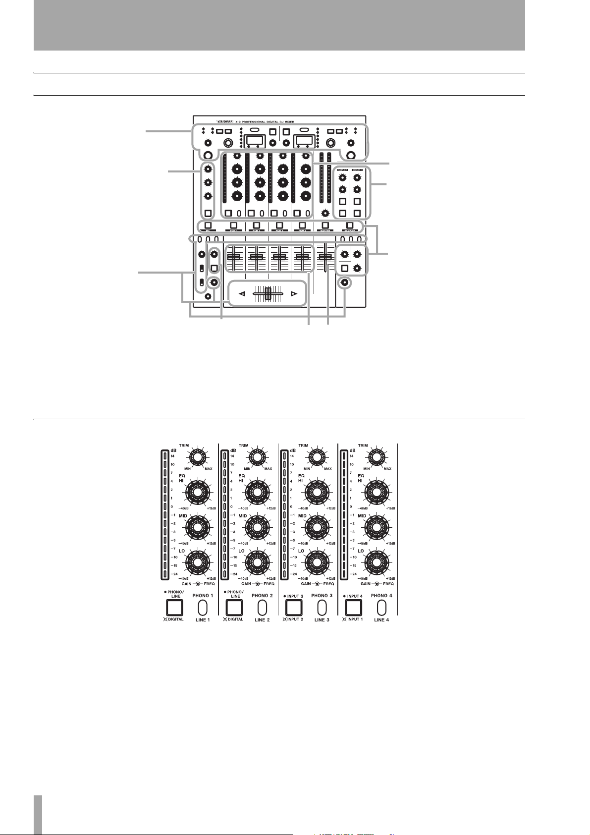
Road map to front panel functions
Effect, menu, etc.
management
Microphone control
Cross-fader
and cross-fader
controls
External
effect
These different sections of the X-9 are described
more fully in other parts of the manual, but this section gives you a quick orientation to help you find
your way around the mixer.
Program faders
Program level,
EQ and
assignment
section
Sampler
section
Cue selection keys
and monitoring
controls
Master fader
See “Connections” on page 10 for details of the rear
panel features and how to make connections between
the X-9 and other equipment.
Program gain level, EQ and assignment section
This section provides the basic mixing facilities to
control the sound received at the inputs, and assigned
to the programs.
See “About programs” on page 14 for details of how
inputs and programs work together and how to use
these controls.
6 TASCAM X-9 Owner’s Manual
Page 7
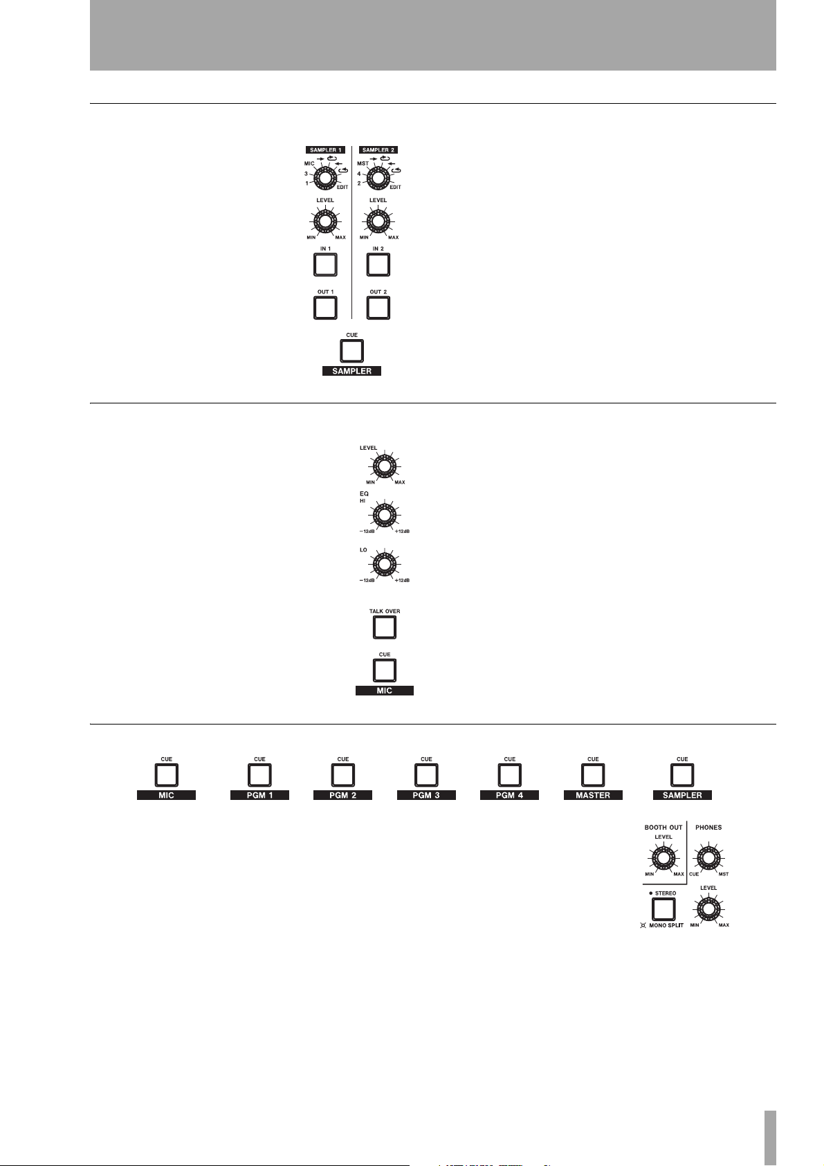
Sampler section
2 Getting acquainted with the X-9
The sampler section provides
the controls for two built-in
samplers.
These are capable of accepting
the input from a variety of
sources (program, microphone
or master mix), and recording
eight seconds of sound (for each
sampler).
You can then play the resulting
sample from the X-9, cue it, etc.
and add it to the overall mix.
Microphone control
This section provides control over the
microphone.
A talkover function, as well as 2-band
EQ, is provided in this section for use
with the microphone.
Samplers can be assigned to the cross-fader signals,
and the cross-fader can be used to start them.
See “Samplers” on page 26 for full details of how to
operate these samplers.
See “Microphone (connection and
use)” on page 11 for full details of how
to use the microphone with the X-9.
Cue selection keys and monitor keys
These keys allow the selection of the programs,
microphone, sampler, etc. for cueing and preview.
The headphones are used for this purpose, and the
booth outputs may be used to provide a second set of
stereo outputs.
See “Headphones (connecting and using)” on
page 12 and “Cue (previewing sounds)” on page 16
for details.
TASCAM X-9 Owner’s Manual 7
Page 8
2 Getting acquainted with the X-9
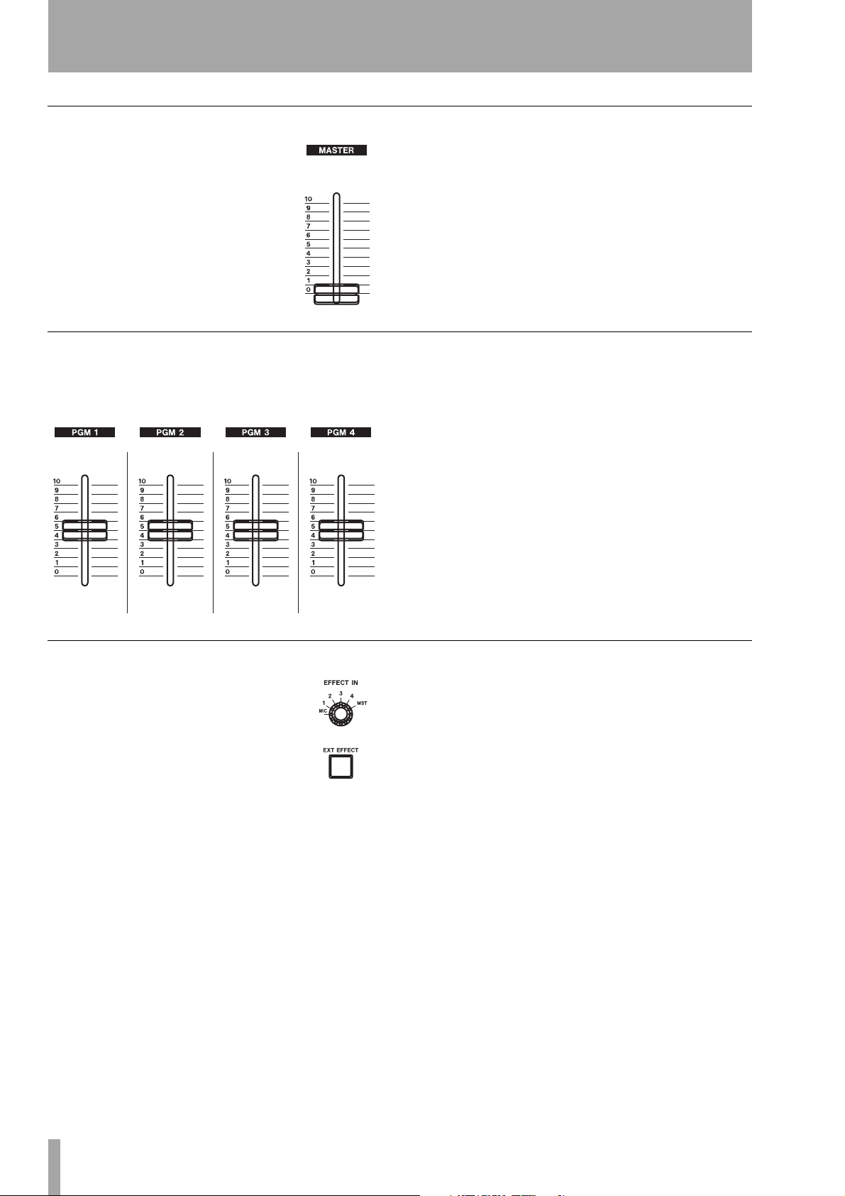
Master fader
The master fader is used to control
the overall level of the mixed signal
output from the X-9.
See “Signal flow” on page 15 for
details of how this works in conjunction with the input, etc., signals in
the X-9.
Program faders
These faders adjust the levels of the programs after
they have been equalized and before they are sent to
either the cross-fader or to the master fader.
External effect
These controls affect the assignment
and the on/off status of any external
effect connected to the X-9.
The fader curve and fader direction can also be set,
and fader program start can be carried out.
See “About programs” on page 14 for details of how
programs and signals interact.
See “Faders” on page 21 for further details about
fader settings.
See “External effects” on page 13 for details of how
to connect and use an external effect processor with
the X-9.
8 TASCAM X-9 Owner’s Manual
Page 9
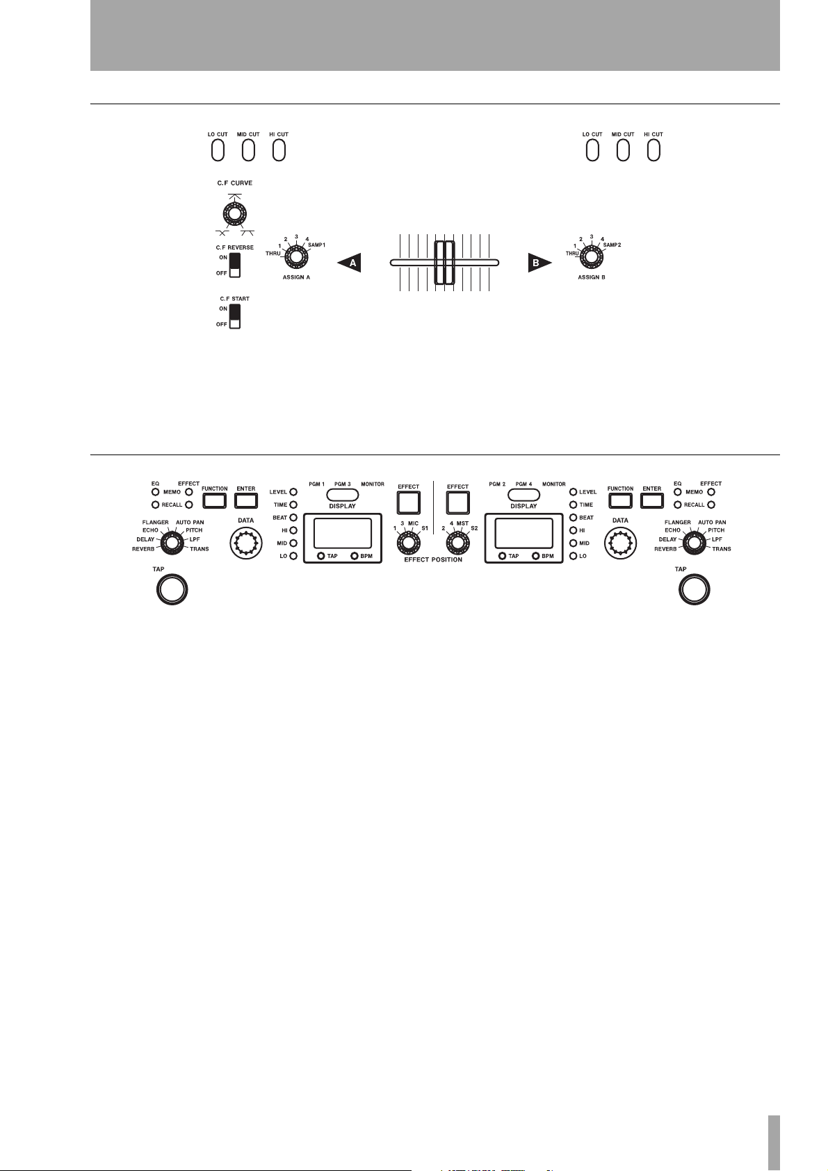
Cross-fader and fader controls
2 Getting acquainted with the X-9
These take care of the A and B outputs which are
assigned to the cross-fader using the
trols, and then passed to the master stereo output.
It is possible to set the cross-fader curve, reversal,
and allow source starting with the cross-fader.
ASSIGN con-
Effect, menu, etc. management
This section handles the effects, the parameter menus
and the equalization memories of the X-9.
See “EQ” on page 28, “Effects” on page 23 and
“Menu reference” on page 17 for details.
See “Cross-fading” on page 14 for details of how
the cross-fader fits into the signal chain.
See “Faders” on page 21 for details of cross-fader
settings.
TASCAM X-9 Owner’s Manual 9
Page 10
3 – Connections
This section gives a brief description of the connections you should make before starting to use the X-9.
WARNING
Make and break all connections between the X-9 and
other equipment with everything turned
make or break connections with the power turned on,
OFF
. If you
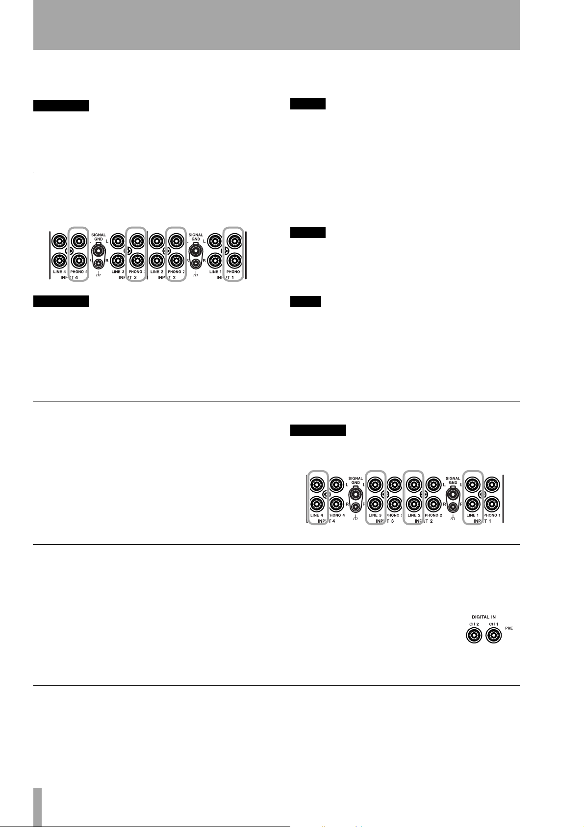
Record turntables
Only connect record turntables to the PHONO connectors (
WARNING
Never connect record turntables to any other type of
connector on the X-9.
Never connect any other type of equipment to the
PHONO
1, 2, 3 or 4).
connectors.
there is a very real risk of damaging the equipment,
including the X-9.
NOTE
All XLR connectors on the X-9 are wired so that pin
1=ground, pin 2= hot and pin 3=cold. Make sure that all
equipment connected using these connectors also conforms to this wiring standard.
If the turntables are fitted with grounding wires, connect these to the ground terminals on the X-9.
NOTE
Note that the X-9 is supplied with eight RCA caps which
should be fitted over the PHONO terminals if they are
not being used. This will help to maintain high signal
quality.
TIP
The X-9 pairs of connectors all have the left connector
at the top and the right at the bottom. Pairs of pin signal cables are typically red for the right channel and
some other color for the left channel.
We explain about connecting other equipment (CD
decks, etc.) including digital connections, below.
CD decks, etc.
Connect CD decks to the LINE connectors (1 through
4) on the rear panel. Unlike record decks, CD decks
do not need to be grounded to the X-9).
Digital connections
The X-9 can be connected to devices which output
SPDIF digital audio through a coaxial output (many
CD players, MD players and DATs, as well as some
electronic musical instruments) and can also output a
digital audio version of the final mix (to a digital
recorder such as a DAT, or a CD recorder, or a suitably-equipped personal computer).
Amplifier system
WARNING
CD decks, etc. should never be attached to the
connections.
PHONO
Use menu item 14dl to set whether the signal is output pre- or post- master fader (“Menu reference” on
page 17).
Use RCA pin jack cables to make connections between the digital outputs of
other equipment and the
DIGITAL IN
connectors of the X-9, and digital inputs of other
equipment and the
DIGITAL OUT of the X-9.
To listen to the X-9, you will need an amplifier and
speaker system, which is connected as explained
here.
10 TASCAM X-9 Owner’s Manual
Page 11
3 Connections
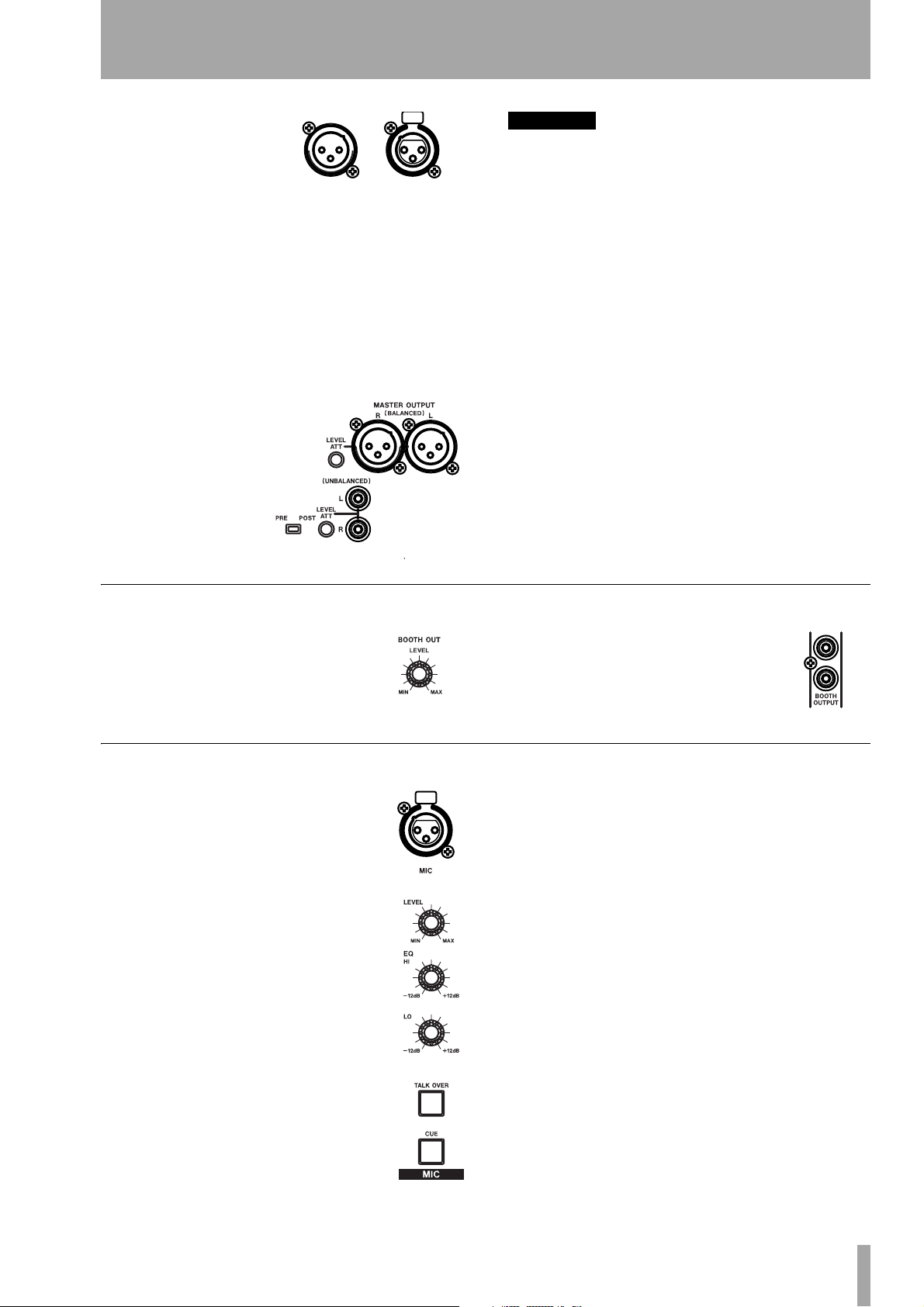
When connecting an amplification system to the X-9,
check the inputs of the
or
amplifier. If they look like
either of the connectors shown here, they are XLR
connectors and are probably balanced.
Check the rear panel of the amplifier, or the amplifier’s manual, to make sure. Amplifiers with balanced inputs should be fed by the
(BALANCED)
output connectors of the X-9.
MASTER OUTPUT
All other connectors (mono 1/4” jack or RCA pin
jacks should be fed by the
(UNBALANCED) RCA pin
outputs.
The level of the output
from the unbalanced
outputs can be set
using the
PRE/POST
switch to be affected
by the master fader
(
POST) or unaffected
by it (
PRE).
WARNING
It is most important to make sure that you make the
correct connections. Connecting the wrong output of
the X-9 to the amplification system can result in overheating and possible damage to both the X-9 and to
the amplification system.
If you are in any doubt at all, we strongly suggest that
you consult your TASCAM dealer or other qualified
audio professional regarding the interconnection of
your system.
Use the trimmer potentiometers (LEVEL ATT) to
adjust the output level to the amplification systems.
Again, you may find it useful to consult the amplification system documentation and/or consult a professional sound engineer.
Booth outputs
The booth outputs provide you with a second mix where the level is not controlled
by the master fader, but by the
LEVEL
volume control.
BOOTH
Microphone (connection and use)
To input your voice through the X-9 system, you need to connect a microphone
to the system. The X-9 provides an XLR
connector for connecting a standard
(dynamic) microphone.
Connect your favorite microphone to
this connector.
Use the
the signals except the microphone by
20 dB (the key lights when active).
Adjust the level of the microphone signal sent to the master fader with the
LEVEL control.
TALK OVER key to “dim” all
Connect the unbalanced
OUTPUT
RCA jacks to the unbalanced
BOOTH
inputs of the booth amplification system.
Use the menu system (
18bm) to change the left-right
balance of the microphone signal.
You can also select the microphone signal to be
passed through the internal or external effects, as
well as being used as a source for sampler 1.
The microphone signal can be cued (see “Cue (previewing sounds)” on page 16) in the same way as
program signals, using the
CUE key (lights when
active).
Adjust the tone of the microphone signal
with the
HI (treble) and LO (bass) EQ
controls.
TASCAM X-9 Owner’s Manual 11
Page 12

3 Connections
External effects unit
Use the SEND and
RETURN 1/4” jacks to
connect any external
effects unit. For full
Headphones (connecting and using)
Connect a standard pair of stereo headphones to the stereo 1/4” jack on the top
or at the front of the X-9. These two
jacks output the same signals and are
controlled by the same controls.
Use the headphone
LEVEL
control to adjust the volume of the signal from the headphones.
There are four EQ settings, which
can be made using the menu system (menu
01HP)—see “Menu
reference” on page 17. These settings boost either the
low or the high part of the frequency range, or both.
The fourth setting is a “normal” setting—no cut or
boost.
PHONES
details of connection and use of an external unit, see
“External effects” on page 13
The balance between the cue mix (see “Cue (previewing sounds)” on page 16) and the master cue
mix in the headphones is set using the upper
PHONES control. Turn counterclockwise for cue sig-
nals (
CUE) and clockwise for main master cue mix
(
MST).
In addition, the headphone output can be in stereo
outputs or set so that the left headphone outputs the
cue signal (in mono, of course) and the right headphone outputs the master main signal (in mono).
Use the STEREO (the indicator is unlit)/
SPLIT
(indicator is lit) key to change between these
MONO
two modes.
In the
MONO SPLIT mode, the cue signal is output
from the left headphone, and the master cue signal
from the right headphone. Use the
CUE/MST control
to adjust the relative levels.
Fader start/stop connections
The four mono mini-jacks (3.5 mm)
are connected so that the tip feeds a
fader start, and the sleeve feeds a fader
stop.
The ground for these connections is
provided by the signal ground of the device to which
the fader start is made.
NOTE
Even if the device is connected digitally to the X-9 (such
as a CD or MD player) for the audio connection, an ana-
Footswitches
You can connect one or two
(optional) footswitches, such as
the TASCAM RC-30P model, to
the X-9’s
FOOT SW jacks.
log connection must also be made to provide the
ground for the fader start.
Note that the fader start control refers to the program
number—see “About programs” on page 14 (not the
device number).
To activate fader start/stop for individual programs,
follow the instructions in “Fader start” on page 21.
To activate fader start/stop for the devices assigned to
the cross-fader signals, follow the instructions in
“Cross-fader start” on page 22.
These footswitches can be used for a variety of purposes, such as sampler control, effect on and off, etc.
Use the menu item (
08Ft) (“Menu reference” on
page 17) for full details of how these switches can be
set up.
12 TASCAM X-9 Owner’s Manual
Page 13

External effects
3 Connections
The X-9 can send signals to and accept return signals
from an external effects unit.
Such a unit can be connected using the
effects unit) and
RETURN (from the effects unit)
SEND (to the
jacks.
If the effects unit is only capable of accepting a mono
input, read the documentation supplied with the
effects unit, and make the appropriate connection to
the
L effect SEND jack of the X-9.
If the effects unit is only capable of producing a
mono output, read the documentation supplied with
the effects unit, and make the appropriate connection
to the
L RETURN jack of the X-9.
NOTE
The return from the external input cannot be output
from the digital output.
To use the external effects unit
Turn the EFFECT IN knob to select the
signal that will be processed by the
effects unit: a program (
microphone signal (
mix (
MST).
Adjust the input level to the effects unit
and the output level of the signal from the effects unit
using the controls of the external unit.
Turn the effect loop on and off with the
EFFECT
key (it lights when the loop is active).
It is also possible to use an external effects unit
through the footswitches (see “Footswitch assignment” on page 18 for details of this menu setting
(
08Ft))).
TIP
For a strange effect, you can send and return the left
channel of a program through one effects unit, and the
right channel of the same program through another
effects unit with different settings.
1 through 4), the
MIC) or the master
EXT
TASCAM X-9 Owner’s Manual 13
Page 14

4 – Learning more
The X-9 has four sets of inputs, as well as the two
built-in samplers and the microphone input, all of
which can be mixed and used as sound sources.
There are a number of different signals that can be
fed into the X-9: up to four turntables, and four other
About programs
These inputs are assigned to four mixer channels
(modules), known as programs, and numbered from
1 through 4, The levels of the programs are controlled using program faders.
analog devices, and two digital devices, not to mention the two internal samplers and the microphone.
In order to understand the X-9, it is necessary to get a
basic idea of where the signals go.
In addition, each program is equipped with 3-band
sweppable sweepable EQ, with variable Q, and a trim
control.
The left-right balance of each program is adjusted
using the menu system with
22b4 (see “Menu reference” on page 17).
19b1, 20b2, 21b3 and
Assigning sources to programs
Use the switches on the top panel to change between
LINE and PHONO inputs.
the
In addition, there is a key beside each of these
switches, allowing you to choose different sources
for the programs:
Tri m
When the inputs have been assigned,
adjust the level fed to the equalizer, and
then the fader, using the program’s
control.
TRIM
The keys for programs 1 and 2 allow the digital
inputs to be selected as an alternative to the PHONO/
LINE
pair. When the indicators for these keys are lit
(the digital is selected), the
no effect.
The keys for programs 3 and 4 allow input 2 to be
selected for program 3 and/or input 1 to be selected
for program 4. The meaning of inputs 1 and 2 is
decided by the
and by the digital selection keys.
This provides 38 dB of adjustment. Note that turning
this control too far clockwise with a powerful input
signal may result in a distorted signal.
PHONO/LINE switches for 1 and 2
PHONO/LINE switch has
Cross-fading
When the two program sources have been assigned
as shown above (“About programs” on page 14), they
14 TASCAM X-9 Owner’s Manual
can be transferred to the outputs through the crossfader and then through the master fader.
Page 15

4 Learning more
The two signals that are controlled by the cross-fader
are known as
A and B.
You can set these to be any of the following using the
ASSIGN A and ASSIGN B controls below and to the
right and left of the program faders:
Programs 1 through 4, a sam-
pler (
SAMP 1 for A, and
SAMP 2 for B) or THRU.
The
THRU setting is equivalent
Note that this is SAMP1
for the ASSIGN A control
to OFF. In other words, if either
Signal flow
The signal flow is therefore:
the
ASSIGN A or the ASSIGN B control is set to
THRU, no signal is assigned to go through the cross-
fader on that side, and moving the cross-fader to the
side with the
When
THRU setting has no effect on that side.
THRU is selected, use the appropriate program
fader(s) and the master fader.
Move the fader from the left (fully A signal only) to
the right (fully B signal only) to perform the crossfade between the two signals.
Incoming signals are
assigned to programs
Programs (and samplers)
are assigned to the
cross-fader A and B
signals
Programs (and
samplers not
assigned to the
cross-fader) go
straight to the
master, together
with the mic
The cross-fader
determines the A and B
levels sent to the master
The master outputs
(what your audience
hears)
TASCAM X-9 Owner’s Manual 15
Page 16

4 Learning more
Playing a song
When you have made connections as described in
“Connections” on page 10, you can start playing a
song.
With the program fader at its lowest level (0) and the
master fader also at 0, load a CD in the player, or put
a record on the turntable connected in the earlier step
Adjusting the output volume
Set the amplifier volume to less than full setting.
Bring the
slowly bring adjust the program fader until the overall level is what you want.
Use the program meter to view the level of the program signal, and the stereo
the overall level of the signal fed from the X-9 outputs.
If the top segment of a meter (
of the time, the sound coming out of the X-9 will be
MASTER fader up to about the 7 mark, and
MASTER meters to check
14 dB) is lit for most
(“Record turntables” on page 10 and “CD decks,
etc.” on page 10).
Cue up the CD or record using the cue functions as
described below (use headphones to monitor the
CUE output while the
CUE indicator for the program
with the record is lit).
distorted. You should therefore try to keep the level
so that the red segments of the meters are not lit all
the time.
You can set the time that the meters take to fall back,
as well as the time that they hold peak values, using
the
12Mr and 13Mp menus (see “Meter release time”
on page 19 and “Meter peak hold time” on page 19).
TIP
We suggest this way of working to avoid possible overloading of the internal amplifiers, and distortion caused
by such overloading.
Cue (previewing sounds)
The X-9’s cue system allows you to preview a program through headphones before playing it back
through the main amplifier system.
Use the controls as described in
“Headphones (connecting and
using)” on page 12 to select the
cue output to the headphones.
Press any of the program
keys, the microphone
The programs and samplers, are monitored done prefader (that is, moving the program fader or adjusting
the sampler
LEVEL controls has no effect on the
monitor signal level). On the other hand, the master
cue output is monitored post-fader (moving the master fader affects the monitoring volume).
CUE
CUE key,
the sampler
CUE key or the MASTER cue key to lis-
ten to the cue signal for that source.
When one of these keys is active (that is, the source is
routed through the cue mix to the headphones), the
key is lit.
Remember that no monitoring of the cue signals is
possible if none of the
The microphone is monitored after the
CUE keys is lit.
LEVEL con-
trol.
Use the
CUE/MST headphone control to adjust the
balance between the cue and master signals in the
headphones.
16 TASCAM X-9 Owner’s Manual
Page 17

5 – Menus
The X-9 uses a menu system to allow various functions to be enabled.
You should read through the menu section (“Menu
reference” on page 17) to find out exactly what is
possible—the X-9 may possibly do more than you
first thought, thanks to the menu system.
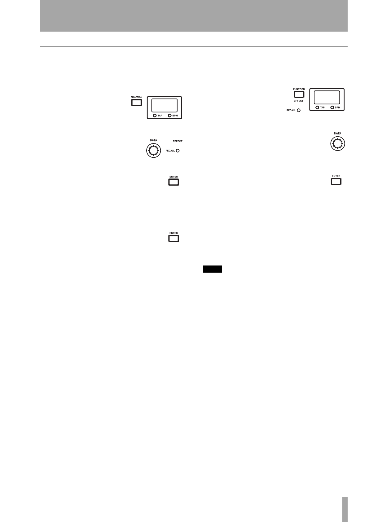
To use the menus:
3
1
5
7
4
6
2
1 Press the
2 Turn t he
FUNCTION key.
DATA knob to select the menu
description (a 4-character code shown on the
display).
3 Press
ENTER to confirm that you want to use
this menu.
4 Turn the
DATA knob to change the value for
the menu.
5 Some menus have only one setting. For these
menus, press
ENTER to confirm the setting
and leave the menu system.
For menus with two settings (for example,
first selecting the sampler whose settings will
be changed and then changing the setting),
press ENTER to confirm the first setting.
6 Turn the
7 Press
DATA knob to set the next value.
ENTER to confirm the setting and leave
the menu system.
Typically, most menus can be performed using either
the right and left menu systems (consisting of keys,
dial and display).
The menus and the different settings you can make
are listed in “Menu reference” on page 17.
These menu controls are also used with the effects
units, as explained here (“Effects” on page 23).
How the X-9 shows characters
It’s usually fairly clear what’s being shown on the X9 display. However, you may want to refer to this
ABCDEFGHI J KL MNOPQRST UVWXYZ
ABcDEFGHIJKLMNOPQRSTUVWXYZ
0123456789- _+
0123456789-_+
chart if you are not quite sure how things are being
shown:
Menu reference
The following table provides a list of the menu
options available on the X-9, together with the
parameters available and their meaning.
In this table, default (factory) settings are marked
with a *.
See “Menus” on page 17 for details of how to use the
menu system.
TASCAM X-9 Owner’s Manual 17
Page 18

5 Menus
Function
Headphone EQ
Program 1 fader
start
Program 2 fader
start
Program 3 fader
start
Program 4 fader
start
Cross-fader A start
Menu
display
01HP
02F1
03F2
04F3
05F4
6cFA
Meaning Available settings Notes
Sets headphone EQ to
normal, high or low
boost
Sets fader start for program 1 on or off
Sets fader start for program 2 on or off
Sets fader start for program 3 on or off
Sets fader start for program 4 on or off
Sets the cross-fader to
start signal A playback
nOr
* (no EQ)
H
High boost
L
Low boost
HL
High and low boost
OFF
* Fader start disabled
On
Fader start enabled
OFF
* Fader start disabled
On
Fader start enabled
OFF
* Fader start disabled
On
Fader start enabled
OFF
* Fader start disabled
On
Fader start enabled
OFF
Fader start disabled
On
* Cross-fader starts signal A
playback
Can be performed on
both left and right menu
systems.
Takes immediate effect
before being confirmed.
Can be performed on
both left and right menu
systems.
Can be performed on
both left and right menu
systems.
Can be performed on
both left and right menu
systems.
Can be performed on
both left and right menu
systems.
Can be performed on
both left and right menu
systems.
Cross-fader B start
Footswitch
assignment
EQ memory store
EQ memory recall
7cFb
08Ft
09EM
10Er
Sets the cross-fader to
start signal B playback
Sets the function of the
footswitches connected
to the X-9.
Stores currentlyselected EQ settings to
memory.
Recalls stored EQ memory settings to current
program.
OFF
Fader start disabled
On
* Cross-fader starts signal B
playback
EF
* links to internal effects
(1=effect 1, 2=effect 2)
E
links to external effects (1& 2=
external)
S1
Sampler 1 (1=in, 2=out)
S2
Sampler 2 (1=in, 2=out)
CF
Crossfader (1 on, hard A
side,
1
off, current position; 2
2
on, hard B side,
position)
Use the left menu system for programs 1 and 3.
Use the right menu system for programs 2 and 4.
The
EQ MEMO
When
ENTER
bank number is shown. Use the dial to select a bank.
If the bank already contains a setting, the display shows
SURE
. Press
cancel.
Use the left menu system for programs 1 and 3.
Use the right menu system for programs 2 and 4.
EQ RECALL
The
Use the dial to select a bank containing EQ memory (only
banks containing data are shown).
ENTER
Press
off, current
indicator lights when
is first pressed, the lowest empty memory
ENTER
to overwrite, or any other key to
indicator lights when
to recall the memory.
Can be performed on
both left and right menu
systems.
Can be performed on
both left and right menu
systems.
09EM
is selected
10Er
is selected
18 TASCAM X-9 Owner’s Manual
Page 19

5 Menus
Function
Program EQ Q
values
Meter release time
Meter peak hold
time
Digital out
Menu
display
11_E
12Mr
13MP
14dI
Meaning Available settings Notes
Sets the Q value for the
EQ bands of the
selected program (see
“EQ Q setting” on
page 28)
Sets the meter release
time (see “Adjusting the
output volume” on
page 16).
Sets the meter peak
hold time (“Adjusting the
output volume” on
page 16)
Sets whether the signal
from the digital output is
pre- or post master
fader
After pressing
select the menu, use the dial to
select the band (
M
*=mid, L=low) and press
ENTER
A
low value of Q
nOr
Normal value of Q
B
high value of Q
Value changes as selection is
made. Press
firm.
nor
* Normal
SLO
Slow
All values are in seconds
OFF
0.5
1.0
*
2.0
nOr
* Post-fader signal
rEc
Pre-fader signal
ENTER
.
ENTER
H
=high,
to
to con-
Use the left menu system for programs 1 and
3.
Use the right menu system for programs 2 and
4.
Can be performed on
both left and right menu
systems.
Can be performed on
both left and right menu
systems.
Can be performed on
both left and right menu
systems.
Program fader
curve
Program fader
reverse
Sampler tempo
15Fc
16Fr
17St
Sets the fader curve as
described and shown in
“Program fader “curve””
on page 21.
Sets the fader direction
to reverse as described
in “Program fader direction” on page 21.
Sets the sampler playback pitch for either
sampler 1 or sampler 2.
After pressing
select the menu, use the dial to
select the program fader to be
1, 2, 3
set (
ENTER
Select from the following:
A1
–6 dB
nOr
* –12 dB
A2
–24 dB
Press
After pressing
select the menu, use the dial to
select the program fader to be
1, 2, 3
set (
ENTER
Select:
NOr
* Normal
rEV
Reverse
Press
After pressing
select the menu, use the dial to
select the sampler to be set
(
S1
*, or S2) and press
ENTER
Use the dial to select the value
(from -
ENTER
ENTER
or 4) and press
.
ENTER
ENTER
or 4) and press
.
ENTER
ENTER
.
100
to
100
to confirm.
to
to confirm.
to
to confirm.
to
) and press
Can be performed on
both left and right menu
systems.
Can be performed on
both left and right menu
systems.
Can be performed on
both left and right menu
systems.
When sampler data is
erased, the value is
reset to 0%.
TASCAM X-9 Owner’s Manual 19
Page 20

5 Menus
Function
Mic balance
Program 1 balance
Program 2 balance
Program 3 balance
Program 4 balance
Restore factory
presets
Menu
display
18bM
19b1
20b2
21b3
22b4
23FA
Meaning Available settings Notes
Balances the microphone signal
Balances the program 1
signal
Balances the program 2
signal
Balances the program 3
signal
Balances the program 4
signal
Restore all menu settings to their factory
defaults.
(hard left) L9 to L1,
r1
(center) ,
(hard left) L9 to L1, c0 (center) ,
(hard left) L9 to L1, c0 (center) ,
(hard left) L9 to L1, c0 (center) ,
(hard left) L9 to L1, c0 (center) ,
Press
shows
Press
tory defaults.
to r9 (hard right)
r1
to r9 (hard right)
r1
to r9 (hard right)
r1
to r9 (hard right)
r1
to r9 (hard right)
ENTER
SURE
ENTER
nor
. The display
.
to restore fac-
Can be performed on
both left and right menu
systems.
Can be performed on
both left and right menu
systems.
Can be performed on
both left and right menu
systems.
Can be performed on
both left and right menu
systems.
Can be performed on
both left and right menu
systems.
Can be performed on
both left and right menu
systems.
Clear all EQ
memories
Clear all effect
memories
24AC
25Ec
Clears all EQ memories
Clears all effect memories
Press
ENTER
SURE
shows
Press
ENTER
memories.
ENTER
Press
shows
SURE
ENTER
Press
effect memories.
. The display
.
to clear the
. The display
.
to clear the
Can be performed on
both left and right menu
systems.
Can be performed on
both left and right menu
systems.
20 TASCAM X-9 Owner’s Manual
Page 21

6 – Faders
The X-9 faders are not all that they appear at first
sight! Their behavior can be changed so that their
“curve” can fit your way of working, so that they can
Program fader “curve”
The fader “curve” decides how much the signal is cut
then the fader is moved to the center position away
from the “full on” position.
Fader at full
-6 dB
-12 dB
Volume
-24 dB
A1
nOr
A2
be pulled or pushed to increase the level, and they
can also start and stop other devices connected to the
X-9. See below for details.
The program faders can be set individually (they do
not all have to share the same setting).
The titles in this illustration refer to the explanation
regarding setting as given in “Program fader curve”
on page 19 (
15Fc).
Program fader direction
As shipped, the faders on the X-9 work so that when
you push them away from you, the level of the signal
increases. When the faders are pulled towards you,
the level decreases.
Some people prefer to work the other way round, so
that pulling the faders towards you increases the volume. Each program fader can be set individually to
work the way you prefer. See “Program fader
reverse” on page 19 (
16Fr) for details.
Alternatively, you can set fader reverse in the fol-
lowing way:
Fader start
The program faders can be used for automated start
or stop of remote devices, using the fader start/stop
jacks (see “Program faders” on page 8 for details of
connections, etc.).
Whether the faders control the start/stop of the
remote device is a menu setting, and you can enable
or disable the fader start for each fader individually.
Alternatively, you can use the following method
for setting fader start:
1 Press and hold down a
the matching
2 Press the
ENTER key together.
CUE key of the program to toggle
FUNCTION key and
the fader direction, while holding down the
two keys above. The
CUE key lights when the
fader is reversed.
NOTE
When the fader direction is reversed in this way, the
fader start operation (see “Program fader direction” on
page 21) is also reversed.
1 Press and hold down a
the matching
ENTER key together.
2 Press the program selection key (
LINE /DIGITAL
or INPUT/INPUT) while hold-
FUNCTION key and
PHONO/
ing down the two keys above to toggle fader
start on or off. The selection key lights when
fader start is enabled for the program.
TASCAM X-9 Owner’s Manual 21
Page 22

6 Faders
Cross-fader curve
You can change the way in which the signal is
changed from the A to B signals as the cross-fader is
moved, using the
When this control is fully counter-clockwise, it takes
a relatively large movement of the cross-fader from
C.F CURVE control.
Cross-fader start
When either of the cross-fader start menus (6cFA or
7cFb) has been set (is on, the C.F START switch is
ON position) and a suitable connection has
on the
been made from the
panel which corresponds to the program number
selected), moving the cross-fader to the A and B
source automatically starts that source.
Alternatively, press and hold down one of the
FUNCTION keys and the corresponding ENTER key
together.
While holding the
down, press the
A start on or off.
fader
FADER START jack on the rear
ENTER and FUNCTION keys
EXT EFFECT key to toggle cross-
one side towards the center before the opposite crossfader signal level is increased.
When this control is fully clockwise, the opposite
cross-fader signal is heard after only a small movement of the cross-fader towards the center.
While holding the
down, press the
gle cross-fader
These methods are equivalent to the menu settings,
and changing the settings in this way will also
change the menu settings.
Use the
position to override the menu settings. In
other words, if the switch is
menu settings are on, cross-fader start is disabled.
However, setting this switch to
cally enable cross-fader start if the menu setting is
not set to on.
C.F START switch in the OFF
ENTER and FUNCTION keys
STEREO/MONO SPLIT key to tog-
B start on and off.
OFF, and the
ON will not automati-
Cross-fader reverse
The C.F REVERSE switch is used to
reverse the direction of the cross-fader.
When the switch is set to
of the cross-fader is reversed (that is, mov-
ON, the direction
ing it towards
other way round). The cross-fader start is also
reversed (see “Cross-fader start” on page 22).
A makes the B signal louder and the
22 TASCAM X-9 Owner’s Manual
Page 23

7 – Effects
Use the two built-in effects units to add effects to the
microphone, the four program signals, the samplers
(see “Samplers” on page 26), or the master outputs.
NOTE
For details of connecting and using an external effects
unit, see “External effect” on page 8.
The two internal effects units can be assigned to the
following outputs:
EFFECT 1: microphone, programs 1 and 3 and sam-
pler 1.
Selecting the effect type
Select the effect type (either for
effect 1 or effect 2) using the
selection control:
The available effects are:
EFFECT 2: Programs 2 and 4, the master output, and
sampler 2.
Assign the effects using the effect assignment con-
trols (
EFFECT POSITION), which determine where
the effect will be used:
Turn the effects on and off using the
EFFECT keys. It
is also possible to set the footswitches to turn the
effects on and off (“Footswitch assignment” on
page 18).
REVERB
DELAY
ECHO
FLANGER
AUTO PAN
PITCH
LPF
TRANS
A reverberation to give an effect of space
A repeat effect
Another kind of repeat
A swirling sound
Pans the signal rhythmically from left to right and
back again
A pitch shifter effect
“Low pass filter”, sweeping up and down in a
“wah-wah” effect.
A choppy “transformation” effect.
Editing the effects
Each effect has two parameters which you can
1
change to customize the sound
:
LEVEL the level at which the effect
works.
TIME The time factor which determines
the sound of the effect (for example, the
speed with which an auto-pan goes
between channels)
The time parameter works in conjunction with the:
1. Except for the LPF effect, which has three
parameters. See “Effect parameters” on
page 24 for details.
The BEAT parameter
If the “beat” mode is selected with the EFFECT key
lit, the X-9 will make its best effort to determine the
beat from the music being played from the sourced
selected using the selectin control. This beat is then
used as the basis for setting the effect time parameter.
BEAT parameter, and is used to synchronize the
effect to the received beat of the music or allows
manual setting of the timing. See below for details.
To set the
1 Press the appropriate
LEVEL and TIME parameters:
EFFECT key so that
the indicator lights.
2 Press the
LEVEL or TIME indicator is lit.
If the
LEVEL parameter is selected, use the DATA
FUNCTION key so that either the
knob to set the level of the effect (see the table
below).
If the
TIME parameter is selected, use the DATA knob
to set the parameter.
Press ENTER to select the BEAT mode. The BEAT
indicator lights.
In the “beat” mode, press the
ENTER key as many
times as necessary to select the ratio of the effect
time to the beat (quarter-notes, etc.) as shown in the
display.
TASCAM X-9 Owner’s Manual 23
Page 24

7 Effects
Some music may have rather complex rhythms, and
it may be unable to determine the beat automatically.
If the X-9 cannot determine the timing of
the music automatically, you can use the
TAP key to set the timing.
The
TAP key can also be used to set the
tempo used for the effect when the
not lit.
The different values obtainable here (1, 2, 4, 1/2, etc.)
allow you to set up interesting rhythms matching the
tempo of the music to the effect.
Effect parameters
EFFECT key is
TAP and BPM indicators under the display show
The
whether the timing has been obtained manually
(
TAP) or automatically (BPM).
To exit the
BEAT mode, turn the DATA knob to enter
the time setting mode. Turning the knob again will
edit the time value.
The following are the parameters which may be set
for the X-9’s internal effects:
Effect name LEVEL TIME BEAT
REVERB
DELAY
ECHO
FLANGER
AUTO
PAN
0 to 100 0 to 100 —
0 to 100 1 to 3,500 (ms) 2, 1, 3/4, 1/2,
1/4
0 to 100 1 to 3,500 (ms) 2, 1, 3/4, 1/2,
1/4
0 to 100 10 ms to 16 s 32, 16, 8, 4, 2,
1 1/2
0 to 100 10 ms to 16 s 2, 1, 3/4, 1/2,
1/4
Storing effects
You can store up to 30 of each type of effect with the
settings you have made in the X-9 (these settings are
memorized, even when the power is turned off). This
means 8 types of effect with 30 memories for each
effect = 240 memories in total.
1 Make sure the
it is not, this procedure will not
work).
2 Press and hold the
FUNCTION key for about
two seconds. The
indicator blinks, and the
display shows
(MEMO).
3 Press the
indicator now lights steadily, and
number of the next empty “slot” for
storing effects is shown in the display.
EFFECT key is lit (if
MEMO
MEMO
MEMO
ENTER key. The MEMO
Effect name LEVEL TIME BEAT
PITCH
a
LPF
TRANS
a. The LPF has a third parameter, which is the
frequency at which the filter operates. Press
the FUNCTION key, so that the LEVEL and
TIME indicators both light. Use the DATA
knob to set this value from 0 to 100.
0 to 100 –100% to
+100%
0 to 100 10 to 1,000
(ms)
0 to 100 10 ms to 16 s 2, 1, 3/4, 1/2,
—
32, 16, 8, 4, 2,
1 1/2
1/4
If all the available slots have been filled, the
display alternately shows
1.
4 Use the
DATA knob to select the number of
FULL (FULL) and
the slot to store the effect (if you don’t want
to use the empty one suggested by the X-9 or
if you have to overwrite an existing setting).
The number flashes in the display (or if all
slots are full, the display alternately shows
FULL (FULL) and the number you selected.
5 Press the
ENTER key. If the slot is empty, the
settings are stored in the slot, and the existing
settings are overwritten. If there is data
already in the slot, the display shows
(sure). Press
ENTER to overwrite, FUNCTION
SuRE
to cancel.
6 Exit the store/recall mode by pressing the
FUNCTION key for about 2 seconds or press-
ing the
EFFECT key or changing the effect type with the effect selection control.
24 TASCAM X-9 Owner’s Manual
Page 25
Recalling stored effect settings
7 Effects
There are two procedures, depending on whether the
EFFECT key is lit or not.
If the
EFFECT key is lit…
1 Press and hold the
FUNCTION key for
MEMO
about two seconds. The
display shows
MEMO
(MEMO).
2 Turn t he
DATA knob coun-
terclockwise so that the
effect
RECALL indicator is
flashing.
3 Press the
ENTER key. The RECALL
indicator now lights steadily.
4 Turn t he
DATA knob to choose between the
numbers of the slots which have been filled
(the numbers of empty slots are not shown)
and
dFLt (dFLt—default).
5 Press the
ENTER key to recall the
settings. The effect is activated, and
after one second, the X-9 returns to
the “recalled” status in step 3.
Alternatively:
If the
EFFECT key is not lit…
1 Press and hold the
FUNCTION key for
about two seconds.
The
RECALL indica-
tor lights.
2 Turn the
DATA knob to choose
between the numbers of the slots
which have been filled (the numbers
of empty slots are not shown) and
dFLt (dFLt—default).
3 Press the
ENTER key to recall the
settings. The effect is activated (but
cannot be heard until the
EFFECT
key is lit), and after one second, the X-9
returns to the “recall ready” status in step 2.
In both cases:
Exit the store/recall mode by pressing the
FUNCTION key for about 2 seconds or press-
ing the
EFFECT key or changing the effect
type with the effect selection control.
MEMO
TIP
You can clear all stored effect settings using the menu
system (25Ec). See “Clear all effect memories” on
page 20 for details.
TASCAM X-9 Owner’s Manual 25
Page 26

8 – Samplers
The two samplers can be used to record and play
back samples of up to 8 seconds (each) in length.
Recording a sample
1 Select the source from which you will record
the sampler.
Sampler 1 can take samples from program 1
and program 3 as well as from the microphone. Set the
1, 3 or MIC.
to
Sampler 2 can take samples from program 2
and program 4 as well as from the master
mix. Set the
2, 4 or MST (master).
NOTE
When recording samples, if the sample is recorded from
a program or the master, the level is pre-fader (the
fader has no effect on the level sent to the sampler) and
if it is the microphone, the level is postmicrophone
the sampler).
LEVEL
SAMPLER 1 selection control
SAMPLER 2 selection control to
LEVEL
control controls the level sent to
(the
The sample data is lost when the power to the X-9 is
turned off.
3 Press the appropriate
ple recording, and the
IN key to start the sam-
OUT key to stop the
sample recording (if you wait for eight seconds after pressing the
IN key, recording of
the sample stops automatically).
IN and OUT keys light and flash to show when a
The
point has been recorded.
A flashing key means that the key can now be
pressed to set the point.
A lit key means that the point has been set.
TIP
When you have recorded a sample, you must change
the sampler selection control to one of the playback
modes listed below in “Playing back samples” on
page 26 before you can hear it.
2 Start playing the source.
Playing back samples
The SAMPLER 1 and SAMPLER 2 selection controls
have four settings each controlling playback:
Forward playback (“single shot”)
Looped forward playback
Reverse playback (“single shot”)
Reverse looped playback
Turn the selection control to
the playback type you want to
use for the sampler.
You can select sampler 1 as
the A output or sampler 2 as
the B output. If the sampler is
Note that this is SAMP1
for the ASSIGN A control
not assigned to one of the
cross-fader input signals, the
Also note that you can use the footswitches in place of
the
IN
and
OUT
keys, using the menu option
See “Footswitch assignment” on page 18.
08Ft
.
sampler output is sent straight to the master.
Play back the sample by pressing the appropriate
IN
key, and stop playback (in the case of looped samples) by pressing the
OUT key.
You can also stop sample playback before the end of
the sample by pressing the
If you press the
IN key before the sample has finished
OUT key.
playing, playback starts again from the start of the
sample.
Adjust the final output level with
the sampler’s
LEVEL control.
26 TASCAM X-9 Owner’s Manual
Page 27

If you want to preview the playback, use the
(see “Cross-fading” on page 14).
Editing samples
8 Samplers
SAMPLER CUE key
By editing samples, we mean here the adjustment of
the start and end points of the sample.
When the
control is turned to
both are left in the
SAMPLER 1 or SAMPLER 2 selection
EDIT, the sample can be edited (if
EDIT position, only sampler 1 can
be edited).
Use the left
DATA knob to adjust the start point of the
sample (of course you can only adjust it forward
from the original
IN point).
Erasing samples
When a sample has been recorded, (both the IN and
OUT keys are lit), you can erase the contents of the
sample.
Sample pitch
Use the right
DATA knob to adjust the end point of
the sampler (of course, you can only adjust the position backward from the original
OUT point).
Naturally, the end point of the sample must come
after the start point.
TIP
Don’t forget to turn the sampler selection control away
from the
NOTE
When you are editing samples, you cannot turn the
effect on or off.
Press the
EDIT
position when you’ve finished editing.
IN and OUT keys together to erase the con-
tents of the sampler.
The sampler pitch and tempo can be altered by
±100% using the menu system (
17St).
See (“Sampler tempo” on page 19) for details.
TASCAM X-9 Owner’s Manual 27
Page 28

9 – EQ
Each program has three bands of sweepable EQ with
adjustable Q available for changing the way that the
signal sounds.
Up to 100 settings can be stored, and recalled for
later use.
Even if the settings were stored for one program,
they can be recalled and used again with another program.
The controls for each program consist
of three dual knobs.
The inner knob controls the amount
(
GAIN) that the signal is cut or boosted
for the appropriate band. Turn clockwise to boost, counterclockwise to cut.
The amount that the signal is cut can
be up to 40 dB of cut, and it can be
boosted by up to 12 dB in each band.
EQ Q setting
The ‘Q’ of EQ is how much of the signal is affected
by the equalization.
The outer knob of each pair (
FREQ) controls the fre-
quency on which the band works. Turn clockwise to
affect a higher frequency, counter-clockwise to affect
a lower frequency.
The
HIGH (treble) band can be set to a value between
6 kHz (6,000 Hz) and 20 kHz (20,000 Hz).
The
MID (mid-range) band can be set to a value
between 200 Hz and 6 kHz (6,000 Hz).
The
LOW (bass) band can be set to a value between
20 Hz and 200 Hz.
WARNING
If you turn the
may overload the X-9 and your amplifier, resulting in
distortion. “Back off” using the
occurs.
GAIN
of all bands to a boost signal, you
TRIM
control if this
The higher the Q value, the sharper the EQ curve
(and the smaller part of the signal affected by the
EQ).
High Q value
(b setting)
There are three Q values, which may be set for each
band using the menu system (see “Program EQ Q
values” on page 19 (
11_E)for details).
Cutting the EQ bands
If you want to make an instant cut of 40 dB in one of
the bands, use one of the sets of
and
HI CUT controls to cut the appropriate band
LO CUT, MID CUT
(when the switch is down, the band is cut).
Viewing EQ settings
Because its EQ circuits are digital, the X-9 allows
you to see the exact figures associated with an EQ
setting (for instance, 12 dB of cut at 400 Hz, etc.).
(Low Q value
A setting)
The three settings are
ting) and
NOTE
These controls do not affect the input programs
directly—they affect the signal assigned to the A and B
cross-fade signals.
These controls do not affect the sampler outputs.
b (high Q).
A (low Q), Nor (normal set-
The EQ settings can be viewed for any of the four
programs (but not for the microphone, whose EQ settings cannot be memorized and recalled).
28 TASCAM X-9 Owner’s Manual
Page 29

9 EQ
The left display and controls can be used for programs 1 and 3, and the right for programs 2 and 4.
Use the selector switches to select the program.
Use the menu controls corresponding to the selector
switch to view the settings for the equalization.
Remembering and recalling EQ settings
The menu system is used to store the EQ settings of
the currently-selected program.
Use either the left or the right menu system for this
function, depending on the program. The left display
and menu system are used for programs 1 and 3, and
the right display and menu system are used for programs 2 and 4.
Note that the
MONITOR setting has no meaning in
this mode.
When the
are being made, turn the
LOW indicator is lit. The display shows the fre-
or
EFFECT key is off, and no menu settings
DATA knob until the HI, MID
quency currently set for the program.
Turning either the gain or the frequency control for
the band changes the display to either the frequency
or the gain for that band.
See “EQ memory store” on page 18 and “EQ memory recall” on page 18 about menu functions
10 for an explanation of how these are stored and
09 and
recalled to the 100 memory banks.
All memories can be erased using the menu system
(see “Clear all EQ memories” on page 20—
24Ac)
TASCAM X-9 Owner’s Manual 29
Page 30

10 – Specifications, etc.
I/O specifications
Audio I/O
Analog inputs
LINE 1
Input level –16 dBV
Input impedance 47 k
PHONO 1
Input level –54 dBV
Input impedance 47 k
MIC
Input level –55 dBV
Input impedance 2.7 k
RETURN (L, R
Input level –10 dBV
Input impedance 22 k
Analog outputs
MASTER OUTPUT (BALANCED)
Output level + 4dBu
Output impedance 75
MASTER OUTPUT (UNALANCED)
Output level –10 dBV
Output impedance 1 k
BOOTH OUTPUT
Output level –10 dBV
Output impedance 1 k
SEND (L, R
Output level –10 dBV
Output impedance 1 k
PHONES
Maximum total output level 30 mW + 30 mW
Total load impedance 32
Digital inputs
CH 1, CH 2
Digital output
DIGITAL OUT
through
input
LINE 4
through
)
)
(x 2)
PHONO 4
RCA pin (unbalanced)
Ω
RCA pin unbalanced (with additional
Ω
XLR balanced (female)
Ω
1/4” jack (unbalanced)
Ω
XLR balanced (male)
Ω
RCA pin (unbalanced)
Ω
RCA pin (unbalanced)
Ω
1/4” jack (unbalanced)
Ω
Stereo 1/4” jack
Ω
RCA pin, IEC60958 TYPE I or TYPE II (auto-detect)
RCA pin, IEC60958 TYPE II (SPDIF)
a
a
SIGNAL GND
connector)
a. All XLR connectors are wired 1=ground, 2-live (hot), 3=return (cold)
Control I/O
FADER STOP/START 1
FOOT SW 1, FOOT SW 2 1/4” jack (for use with RC-30P)
through
3.5 mm mini-jack (high=5 V, Low (on)=0 V) Tip=PLAY, GND=READY
4
30 TASCAM X-9 Owner’s Manual
Page 31

Audio specifications
Program equalization
HIGH
(frequency range)
gain –40 dB to +12 dB
MID
(frequency range)
gain –40 dB to +12 dB
LOW
(frequency range)
gain –40 dB to +12 dB
Microphone equalization
HIGH
(frequency range)
gain –12 dB to +12 dB
LOW
(frequency range)
gain –12 dB to +12 dB
Frequency response
LINE
PHONO
MIC
Signal-to-noise ratio
PGM
PHONO
MIC
Total harmonic distortion
LINE
PHONO
MIC
Crosstalk > 70 dB @ 1 kHz
6 kHz to 20 kHz
200Hz to 6kHz
20 Hz to 200 Hz
10 kHz
100 Hz
20 Hz to 20 kHz ±2.0 dB
20 Hz to 20 kHz ±2.0 dB
20 Hz to 20 kHz ±2.0 dB
84 dB (IHF A weighting)
77 dB (IHF A weighting)
70 dB (IHF A weighting)
< 0.025%
< 0.035%
< 0.040%
10 Specifications, etc.
Samplers (1 and 2) 8 seconds of record/playback per sampler
Effector memories 30 x 8 (types) = 240 memories
EQ memories 100
General specifications
Voltage requirements USA/Canada 120 VAC, 60 Hz
U.K./Europe 230 VAC, 50 Hz
Australia 240 VAC, 50 Hz
General export 120 VAC, 60 Hz, 230 VAC, 60 Hz
Power consumption 42 W
Applicable electromagnetic environment E4
Peak inrush current 0.9 A
Dimensions (w x d x h) 320 x 354 x 87(mm)
12.6 x 13.9 x 3.4 (in)
Weight 7 kg (15.4 lb.)
Operating temperature 5°C to 35°C (41°F to 95°F)
Supplied accessories Rack-mounting ears
Rack-mounting kit
Fan cover
Eight RCA plug covers
Optional accessories MIDI/Digital Out board
TASCAM X-9 Owner’s Manual 31
Page 32

10 Specifications, etc.
Dimensional drawing
355 mm (14.4 in)87 mm ( 3.4 in)
320 mm (12.6 in)
32 TASCAM X-9 Owner’s Manual
Page 33

Mounting the X-9 in a rack
10 Specifications, etc.
When mounting the X-9 in a 19” rack, use only the
supplied rack-mount ears and mounting screws, etc.
As shown here, remove the five screws (1) on the left
side of the unit.
Locate and fit the left rack-mount angle (with the fan
cutout) and fasten it to the X-9 using the five screws
removed in the previous step.
Fit the right rack-mount angle in the same way.
Case mounting
WARNING
It is most important that if you are mounting the X-9 in
a rack or in a case, that the supplied fan cover and ventilation cover are fitted as explained here. This ensures
a smooth airflow, and prevents the fan and ventilation
vents from being blocked, which could cause overheating and damage to the X-9.
Remove the two screws (1) on the left side of the X-9
as shown here.
Use the four screws supplied with the fan cover to
attach the fan cover.
Repeat the process for the ventilation cover on the
right side of the X-9.
TASCAM X-9 Owner’s Manual 33
Page 34

10 Specifications, etc.
Block diagram
HEADPHONE OUT 1
HEADPHONE OUT 2
L
R
L
ATT
R
MASTER OUT (BAL)
L
ATT
R
MASTER OUT (UNBAL)
MASTER OUT (DIGITAL)
LEVEL
MST
BALANCE
BOOTH OUT
L
H.P.
EQ
(MENU)
CUE
MST
CUE
R
LEVEL
EFFECT
CROSS
ASSIGN A
THRU
123
FADER
LEVEL
EFFECT 1
CUE BUSS
MASTER BUSS
TO METER
FADE R
BALANCE
FROM RETURN
SEND/RETURN
CUE
(MENU)
TO SEND
EFFECT IN
123
MIC
TO SAMPLER 2
TO/FROM EFFECT 2
EFFECT POSITION
2S24
TO SAMPLER 2
RETURN
L
EXT EFFECT
L
TO SAMPLER 1
R
R
P
FADER
BALANCE
EFFECT 2
INTERNAL EFFECTOR
SEND
EFFECT
ASSIGN B
4
123
SAMP 1
4
SAMP 2
THRU
P
LEVEL
P
CUE
PRE/POST
4
123
4
MST
MIC
MST
DAC
MST
P
CUE
FADER
(MENU)
BALANCE
PRE/POST
FADER
TO SAMPLER 1
(MENU)
BALANCE
STEREO/MONO SPLIT
CUE
(in DSP)
for MASTER
DSP Processing part
L
R
DAC
TALK OVER
P
CUE
(MENU)
FADER
TO SAMPLER 2
P
BALANCE
(MENU)
CUE
CUE
TO SAMPLER 1
BALANCE
(MENU)
TO/FROM EFFECT 1
EFFECT POSITION
1
3
SAMPLER 1
FROM MIC
FROM PGM 1
FROM PGM 3
2S24
S1
MIC
TO/FROM EFFECT 2
EFFECT POSITION
SAMPLER 2
FROM PGM 2
FROM PGM 4
FROM MASTER
MST
FROM RETURN
TO SEND
PHONO/LINE IN
PHONO
LINE IN
L
PHONO IN 1
TO METER
EFFECT IN
DIGITAL
LINE
PHONO
R
TO/FROM EFFECT 1
EFFECT POSITION
123
MIC
TRIM
DIGITAL
PHONO/LINE
LINE
PHONO
L
LINE IN 1
R
1
ADC
4
3
MIC
3-BAND EQ
MST
S1
CUT SW
MIC
LOW/MID/HI
123
DIGITAL
PHONO/LINE
DAC
DIGITAL IN 1
34 TASCAM X-9 Owner’s Manual
TO/FROM EFFECT 1
TO METER
FROM RETURN
EFFECT IN
TRIM
INPUT 3/INPUT 2
LINE
PHONO
R
EFFECT POSITION
123
MIC
INPUT 3
INPUT 2
LINE
PHONO
L
R
LINE IN 3
1S13
ADC
4
MIC
3-BAND EQ
MST
CUT SW
MIC
INPUT 3
LOW/MID/HI
123
INPUT 2
2S24
MST
TO/FROM EFFECT 2
EFFECT POSITION
CUT SW
3-BAND EQ
LOW/MID/HI
ADC
TO METER
FROM RETURN
TO SEND
EFFECT IN
123
4
MST
INPUT 4/INPUT 1
PHONO
LINE IN
PHONO
L
PHONO IN 4
4
MST
MIC
TRIM
INPUT 4
INPUT 1
LINE
LINE
PHONO
R
L
R
LINE IN 4
MIC
123
INPUT 4
INPUT 1
FROM RETURN
TO SEND
4
MIC
MST
123
TO/FROM EFFECT 1
EFFECT POSITION
4
MST
1S13
MIC
TRIM
MIC
ADC
123
2-BAND EQ
MIC
4
MST
2S24
MST
TO/FROM EFFECT 2
EFFECT POSITION
CUT SW
3-BAND EQ
LOW/MID/HI
ADC
TO METER
FROM RETURN
TO SEND
EFFECT IN
123
4
DIGITAL
LINE
R
LINE IN 2
123
MST
MIC
PHONO/LINE
4
MST
PHONO
LINE IN
PHONO/LINE IN
DIGITAL
LINE
PHONO
L
R
PHONO IN 2
MIC
TRIM
PHONO/LINE
PHONO
L
TO SEND
4
MST
DIGITAL
PHONO
LINE IN
DAC
L
DIGITAL IN 2
PHONO IN 3
Page 35

Page 36

X-9
TEAC CORPORATION
Phone: (0422) 52-5082 3-7-3, Nakacho, Musashino-shi, Tokyo 180-8550, Japan
TEAC AMERICA, INC.
Phone: (323) 726-0303 7733 Telegraph Road, Montebello, California 90640
TEAC CANADA LTD.
Phone: 905-890-8008 Facsimile: 905-890-9888 5939 Wallace Street, Mississauga, Ontario L4Z 1Z8, Canada
TEAC MEXICO, S.A. De C.V
Phone: 5-851-5500 Campesinos No. 184, Colonia Granjes Esmeralda, Delegaacion Iztapalapa CP 09810, Mexico DF
TEAC UK LIMITED
Phone: 01923-819699 5 Marlin House, Croxley Business Park, Watford, Hertfordshire. WD1 8TE, U.K.
TEAC DEUTSCHLAND GmbH
Phone: 0611-71580 Bahnstrasse 12, 65205 Wiesbaden-Erbenheim, Germany
TEAC FRANCE S. A.
Phone: 01.42.37.01.02 17 Rue Alexis-de-Tocqueville, CE 005 92182 Antony Cedex, France
TEAC BELGIUM NV/SA
Phone: 0031-162-510210 Oeverkruid 15, NL-4941 VV Raamsdonksveer, Netherlands
TEAC NEDERLAND BV
Phone: 0162-510210 Oeverkruid 15, NL-4941 VV Raamsdonksveer, Netherlands
TEAC AUSTRALIA PTY.,LTD. A.B.N. 80 005 408 462
Phone: (03) 9672-2400 Facsimile: (03)9672-2249 280 William Street, Port Melbourne, Victoria 3000, Australia
TEAC ITALIANA S.p.A.
Phone: 02-66010500 Via C. Cantù 11, 20092 Cinisello Balsamo, Milano, Italy
Printed In Taiwan MA-0608
 Loading...