

Page 1

Technical Publication
Vivid™ E80 / Vivid™ E90 / Vivid™ E95
Proprietary Service Manual
Direction Number: GC091999
Rev. 4
ADVANCED SERVICE DOCUMENTATION.
COPYRIGHT GENERAL ELECTRIC COMPANY.
GE CONFIDENTIAL. UNLICENSED USE BY NON-GE PARTIES IS STRICTLY
PROHIBITED.
© 2015 and 2017 General Electric Company. All Rights Reserved.
Page 2

This manual is a reference for the Vivid E80, Vivid E90 and Vivid E95 ultrasound
systems (Hereafter listed as Vivid E80/E90/E95). All information provided in this
manual is relevant for all three systems unless otherwise specified.
© 2015 and 2017 General Electric Company.
Manufacturer:
GE VINGMED ULTRASOUND AS
Strandpromenaden 45
3191 Horten, Norway
Tel: (+47) 3302 1100 Fax: (+47) 3302 1350
www.gehealthcare.com
Page 3

GE CONFIDENTIAL
Change history
Revision History
Revision Date Reason for change
1 2015-MAY-05 Initial release of manual.
2 2015-MAY-21 • CH-6: Updated: ‘Touch screen calibration’.
• CH-8:
• Updated: ‘Loading the software from USB Flash
Drive (UFD)’
• Added Illustrations in the ‘OLED monitor parts
replacement’ procedures.
• CH-9: Corrected Part number for Main Power Supply.
3 2015-NOV-18 • Update per change of CE notified body to TUV, CE
0123.
• Updated ‘Translation Policy’ (language disclaimers).
• Chapter 9: Added additional parts in ‘Covers and
Bumpers’
• Updated ‘XYZ parts’
• Chapter 9: Added new BEP service parts
• Chapter 9: Added list of probes and probe spare parts
• Chapter 9: Updated ‘Labels’ section
• Chapter 9: Updated ‘Product manuals for Vivid E80/
E90/ E95’
4 2017-JUN-28 Updated per software v202 release.
Other changes:
• Front Matter: Updated ‘Omissions and errors’ due to
changed reporting tool.
• Chapter 3: Updated screen shots and corrected errors.
• Chapter 5: Added block diagram for the Top Console.
• Chapter 7:
• Updated 'InSite Troubleshooting'
• Added ‘Probe tests’ including ‘Probe Assessment
Tool’.
• Chapter 8:
• Updated ‘Tools’.
• Corrected Torque values based on engineering
input. Added missing Torque values.
• Chapter 9:
• Added/updated FRU entries.
• Added illustrations
• Added Icons to highlight hyperlink to replacement
procedures.
Vivid E80/E90/E95 – Proprietary Service Manual i-1
GC091999 Rev. 4
Page 4

GE CONFIDENTIAL
List of Effective Pages (LOEP)
Pages Revision Pages Revision
Front Rev. 4 Chapter 6 Rev. 4
Front matter Rev. 4 Chapter 7 Rev. 4
TOC Rev. 4 Chapter 8 Rev. 4
Chapter 1 Rev. 4 Chapter 9 Rev. 4
Chapter 2 Rev. 4 Chapter 10 Rev. 4
Chapter 3 Rev. 4 Index Rev. 4
Chapter 4 Rev. 4 Rear Cover Rev. 4
Chapter 5 Rev. 4
Please verify that you are using the latest revision of this document. Information
pertaining to this document is maintained on ePDM (GE Healthcare electronic Product
Data Management). If you need to know the latest revision, contact your distributor, local
GE Sales Representative or in the USA call the GE Ultrasound Clinical Answer Center at
1 800 682 5327 or 1 262 524 5698.
i-2 Vivid E80/E90/E95 – Proprietary Service Manual
GC091999
Rev. 4
Page 5
GE CONFIDENTIAL
Important precautions
Translation policy
Vivid E80/E90/E95 – Proprietary Service Manual i-3
GC091999 Rev. 4
Page 6
GE CONFIDENTIAL
i-4 Vivid E80/E90/E95 – Proprietary Service Manual
GC091999
Rev. 4
Page 7
GE CONFIDENTIAL
Vivid E80/E90/E95 – Proprietary Service Manual i-5
GC091999 Rev. 4
Page 8

GE CONFIDENTIAL
i-6 Vivid E80/E90/E95 – Proprietary Service Manual
GC091999
Rev. 4
Page 9
GE CONFIDENTIAL
Vivid E80/E90/E95 – Proprietary Service Manual i-7
GC091999 Rev. 4
Page 10
GE CONFIDENTIAL
i-8 Vivid E80/E90/E95 – Proprietary Service Manual
GC091999
Rev. 4
Page 11

GE CONFIDENTIAL
Vivid E80/E90/E95 – Proprietary Service Manual i-9
GC091999 Rev. 4
Page 12
GE CONFIDENTIAL
i-10 Vivid E80/E90/E95 – Proprietary Service Manual
GC091999
Rev. 4
Page 13
GE CONFIDENTIAL
Vivid E80/E90/E95 – Proprietary Service Manual i-11
GC091999 Rev. 4
Page 14
GE CONFIDENTIAL
i-12 Vivid E80/E90/E95 – Proprietary Service Manual
GC091999
Rev. 4
Page 15
GE CONFIDENTIAL
Vivid E80/E90/E95 – Proprietary Service Manual i-13
GC091999 Rev. 4
Page 16

GE CONFIDENTIAL
i-14 Vivid E80/E90/E95 – Proprietary Service Manual
GC091999
Rev. 4
Page 17
GE CONFIDENTIAL
Vivid E80/E90/E95 – Proprietary Service Manual i-15
GC091999 Rev. 4
Page 18

GE CONFIDENTIAL
Damage in transportation
All packages should be closely examined at time of delivery. If
damage is apparent, write “Damage in Shipment” on ALL copies
of the freight or express bill BEFORE delivery is accepted or
“signed for” by a GE representative or hospital receiving agent.
Whether noted or concealed, damage MUST be reported to the
carrier immediately upon discovery, or in any event, within 14
days after receipt, and the contents and containers held for
inspection by the carrier. A transportation company will not pay a
claim for damage if an inspection is not requested within this
14-day period.
Certified electrical contractor statement - For USA Only
All electrical installations that are preliminary to positioning of
the equipment at the site prepared for the equipment shall be
performed by licensed electrical contractors. Other connections
between pieces of electrical equipment, calibrations, and testing
shall be performed by qualified GE personnel. In performing all
electrical work on these products, GE will use its own specially
trained field engineers. All of GE’s electrical work on these
products will comply with the requirements of the applicable
electrical codes.
The purchaser of GE equipment shall only utilize qualified
personnel (i.e. GE field engineers, personnel of third-party
service companies with equivalent training, or licensed
electricians) to perform electrical servicing on the equipment.
Omission and errors
If there are any omissions, errors or suggestions for improving
this documentation, contact the GE Ultrasound Global
Documentation Group with specific information listing the
system type, manual title, part number or direction number,
revision number, page number and suggestion details.
Mail the
information to:
GE Vingmed Ultrasound AS
Service Documentation
P. O. Box 141
NO-3191 HORTEN
NORWAY
GE employees should use Post-Market Quality Management
(PQM) to report service documentation issues.
i-16 Vivid E80/E90/E95 – Proprietary Service Manual
GC091999
Rev. 4
Page 19

GE CONFIDENTIAL
WARNING
Service Safety Considerations
DANGER DANGEROUS VOLTAGES, CAPABLE OF CAUSING DEATH,
ARE PRESENT IN THIS EQUIPMENT. USE EXTREME
CAUTION WHEN HANDLING, TESTING AND ADJUSTING.
Use all Personal Protection Equipment (PPE) such as gloves,
safety shoes, safety glasses, and kneeling pads, to reduce the
risk of injury.
For a complete review of all safety requirements, see: ‘Safety
considerations’ on page 1-17.
Legal notes
The contents of this publication may not be copied or duplicated
in any form, in whole or in part, without prior written permission
of GE.
GE makes no representations or warranties with respect to the
information herein. In addition, the information is subject to
change without notice. Every precaution has been taken in the
preparation of this document. Nevertheless, GE assumes no
responsibility for errors, omissions, or any damages, including
special or consequential, resulting from the use of this
information. GE will issue updates to this information
periodically, as needed. If there are any questions regarding the
information contained in this manual, please contact your
GE Representative.
Vivid E80/E90/E95 – Proprietary Service Manual i-17
GC091999 Rev. 4
Page 20

Proprietary to GE
GE CONFIDENTIAL
Permission to use this Advanced Service Software and related
documentation (herein called the Material) by persons other
than GE employees is provided only under an Advanced
Service Package License relating specifically to this Proprietary
Material. This is a different agreement from the one under which
operating and basic service software is licensed. A license to
use operating or basic service software does not extend to or
cover this software or related documentation.
If you are a GE employee or a customer who has entered into
such a license agreement with GE to use this proprietary
software, you are authorized to use this Material according to
the conditions stated in your license agreement.
However, you do not have the permission of GE to alter,
decompose or reverse-assemble the software, and unless you
are a GE employee, you may not copy the Material. The
Material is protected by Copyright and Trade Secret laws; the
violation of said laws can result in civil damages and criminal
prosecution.
If you are not party to such a license agreement or a GE
Employee, you must exit this Material now.
Trademarks
All products and their name brands are trademarks of their
respective holders.
Copyrights
© 2015 and 2017 by General Electric Company. All Rights Reserved.
i-18 Vivid E80/E90/E95 – Proprietary Service Manual
GC091999
Rev. 4
Page 21

GE CONFIDENTIAL
Translation policy - - - - - - - - - - - - - - - - - - - - - - - - - - - - - - - - - - - - - - - - i-3
Damage in transportation - - - - - - - - - - - - - - - - - - - - - - - - - - - - - - - - - i-16
Certified electrical contractor statement - For USA Only - - - - - - - - - - - - i-16
Omission and errors - - - - - - - - - - - - - - - - - - - - - - - - - - - - - - - - - - - - - i-16
Service Safety Considerations - - - - - - - - - - - - - - - - - - - - - - - - - - - - - - i-17
Legal notes - - - - - - - - - - - - - - - - - - - - - - - - - - - - - - - - - - - - - - - - - - - i-17
Proprietary to GE - - - - - - - - - - - - - - - - - - - - - - - - - - - - - - - - - - - - - - i-18
Trademarks - - - - - - - - - - - - - - - - - - - - - - - - - - - - - - - - - - - - - - - - - - - i-18
Copyrights - - - - - - - - - - - - - - - - - - - - - - - - - - - - - - - - - - - - - - - - - - - - i-18
Table of Contents
Chapter 1 — Introduction
Overview
Contents in this chapter - - - - - - - - - - - - - - - - - - - - - - - - - - - - - - - - - - - 1-2
Manual Overview
Introduction - - - - - - - - - - - - - - - - - - - - - - - - - - - - - - - - - - - - - - - - - - - 1-3
Contents in this manual - - - - - - - - - - - - - - - - - - - - - - - - - - - - - - - - - - - 1-3
Typical users of the Basic Service Manual - - - - - - - - - - - - - - - - - - - - - 1-4
Typical users of the Proprietary Service Manual - - - - - - - - - - - - - - - - - 1-4
Vivid E80/E90/E95 models covered by this manual - - - - - - - - - - - - - - - 1-5
Product description - - - - - - - - - - - - - - - - - - - - - - - - - - - - - - - - - - - - - - 1-6
Important conventions
Conventions used in book - - - - - - - - - - - - - - - - - - - - - - - - - - - - - - - - - 1-7
Standard hazard icons - - - - - - - - - - - - - - - - - - - - - - - - - - - - - - - - - - - 1-9
Product icons
Vivid E80/E90/E95 labels - - - - - - - - - - - - - - - - - - - - - - - - - - - - - - - - 1-11
For China only - - - - - - - - - - - - - - - - - - - - - - - - - - - - - - - - - - - - - - - - 1-14
Label locations
Safety considerations
Contents in this section - - - - - - - - - - - - - - - - - - - - - - - - - - - - - - - - - - 1-17
Introduction - - - - - - - - - - - - - - - - - - - - - - - - - - - - - - - - - - - - - - - - - - 1-17
Human Safety - - - - - - - - - - - - - - - - - - - - - - - - - - - - - - - - - - - - - - - - 1-17
Mechanical safety - - - - - - - - - - - - - - - - - - - - - - - - - - - - - - - - - - - - - - 1-20
Electrical safety - - - - - - - - - - - - - - - - - - - - - - - - - - - - - - - - - - - - - - - 1-23
Dangerous procedure warnings
Lockout/Tagout (LOTO) requirements
Returning probes and repair parts
Electromagnetic compatibility (EMC)
What is EMC? - - - - - - - - - - - - - - - - - - - - - - - - - - - - - - - - - - - - - - - - 1-29
Compliance - - - - - - - - - - - - - - - - - - - - - - - - - - - - - - - - - - - - - - - - - - 1-29
Table of Contents
Vivid E80/E90/E95 – Proprietary Service Manual i-19
GC091999 Rev. 4
Page 22

GE CONFIDENTIAL
Electrostatic discharge (ESD) prevention - - - - - - - - - - - - - - - - - - - - - 1-30
Customer assistance
Contact information- - - - - - - - - - - - - - - - - - - - - - - - - - - - - - - - - - - - - 1-31
Phone numbers for Customer Assistance - - - - - - - - - - - - - - - - - - - - - 1-32
System manufacturer - - - - - - - - - - - - - - - - - - - - - - - - - - - - - - - - - - - 1-33
Chapter 2 — Site Preparations
Overview
Contents in this chapter - - - - - - - - - - - - - - - - - - - - - - - - - - - - - - - - - - - 2-2
General Ultrasound system requirements
Contents in this section - - - - - - - - - - - - - - - - - - - - - - - - - - - - - - - - - - 2-3
Ultrasound system environmental requirements- - - - - - - - - - - - - - - - - - 2-3
Electrical requirements - - - - - - - - - - - - - - - - - - - - - - - - - - - - - - - - - - - 2-5
EMI limitations - - - - - - - - - - - - - - - - - - - - - - - - - - - - - - - - - - - - - - - - - 2-9
EMI prevention/abatement- - - - - - - - - - - - - - - - - - - - - - - - - - - - - - - - 2-10
Probes environmental requirements - - - - - - - - - - - - - - - - - - - - - - - - - 2-11
Time and manpower requirements - - - - - - - - - - - - - - - - - - - - - - - - - - 2-11
Facility needs
Contents in this section - - - - - - - - - - - - - - - - - - - - - - - - - - - - - - - - - - 2-12
Purchaser responsibilities - - - - - - - - - - - - - - - - - - - - - - - - - - - - - - - - 2-12
Required facility needs - - - - - - - - - - - - - - - - - - - - - - - - - - - - - - - - - - 2-14
Desirable features- - - - - - - - - - - - - - - - - - - - - - - - - - - - - - - - - - - - - - 2-15
Minimal floor plan suggestion- - - - - - - - - - - - - - - - - - - - - - - - - - - - - - 2-15
Recommended floor plan suggestion - - - - - - - - - - - - - - - - - - - - - - - - 2-16
Suggested floor plan, Ultrasound system, and
EchoPAC PC in same room- - - - - - - - - - - - - - - - - - - - - - - - - - - - 2-17
Networking setup requirements - - - - - - - - - - - - - - - - - - - - - - - - - - - - 2-18
Environmental Dangers
Patient Vicinity UL60601-1 (USA) - - - - - - - - - - - - - - - - - - - - - - - - - - - 2-20
Patient Environment IEC60601-1 (IEC60601-1-1) and
ANSI AAMI ES60601-1 - - - - - - - - - - - - - - - - - - - - - - - - - - - - - - - 2-21
Chapter 3 — System Setup
Overview
Contents in this chapter - - - - - - - - - - - - - - - - - - - - - - - - - - - - - - - - - - - 3-2
Setup reminders
Average setup time - - - - - - - - - - - - - - - - - - - - - - - - - - - - - - - - - - - - - - 3-3
Setup warnings- - - - - - - - - - - - - - - - - - - - - - - - - - - - - - - - - - - - - - - - - 3-3
Receiving and unpacking the equipment
Purpose of this section - - - - - - - - - - - - - - - - - - - - - - - - - - - - - - - - - - - 3-5
Contents in this section - - - - - - - - - - - - - - - - - - - - - - - - - - - - - - - - - - - 3-5
Warnings for receiving and unpacking - - - - - - - - - - - - - - - - - - - - - - - - 3-5
The Tilt and Shock indicators - - - - - - - - - - - - - - - - - - - - - - - - - - - - - - - 3-7
If Shock Indicator has triggered or is missing- - - - - - - - - - - - - - - - - - - - 3-8
If Tilt Indicator has triggered or is missing - - - - - - - - - - - - - - - - - - - - - - 3-9
Position of the Tilt & Shock indicators - - - - - - - - - - - - - - - - - - - - - - - - 3-10
Receiving the Vivid E80/E90/E95 - - - - - - - - - - - - - - - - - - - - - - - - - - 3-11
Unpacking the Vivid E80/E90/E95 - - - - - - - - - - - - - - - - - - - - - - - - - - 3-14
i-20 Vivid E80/E90/E95 – Proprietary Service Manual
GC091999
Rev. 4
Page 23

GE CONFIDENTIAL
Packing materials - recycling information
Preparing for setup
Verify customer order - - - - - - - - - - - - - - - - - - - - - - - - - - - - - - - - - - - 3-21
Physical inspection - - - - - - - - - - - - - - - - - - - - - - - - - - - - - - - - - - - - - 3-21
EMI protection - - - - - - - - - - - - - - - - - - - - - - - - - - - - - - - - - - - - - - - - 3-21
Completing the setup
Purpose of this section - - - - - - - - - - - - - - - - - - - - - - - - - - - - - - - - - - 3-22
Contents in this section - - - - - - - - - - - - - - - - - - - - - - - - - - - - - - - - - - 3-22
System specifications - - - - - - - - - - - - - - - - - - - - - - - - - - - - - - - - - - - 3-23
Electrical specifications - - - - - - - - - - - - - - - - - - - - - - - - - - - - - - - - - - 3-24
Connections on the I/O Rear Panel - - - - - - - - - - - - - - - - - - - - - - - - - 3-25
Connections on the Patient I/O panel - - - - - - - - - - - - - - - - - - - - - - - - 3-26
Connecting probes - - - - - - - - - - - - - - - - - - - - - - - - - - - - - - - - - - - - - 3-27
Power on/Boot up - - - - - - - - - - - - - - - - - - - - - - - - - - - - - - - - - - - - - - 3-29
Power shut down - - - - - - - - - - - - - - - - - - - - - - - - - - - - - - - - - - - - - - 3-29
Complete power down- - - - - - - - - - - - - - - - - - - - - - - - - - - - - - - - - - - 3-29
Configuration
Purpose of this section - - - - - - - - - - - - - - - - - - - - - - - - - - - - - - - - - - 3-30
Contents in this section - - - - - - - - - - - - - - - - - - - - - - - - - - - - - - - - - - 3-30
Vivid E80/E90/E95 configuration - - - - - - - - - - - - - - - - - - - - - - - - - - - 3-31
Service Screen setup - - - - - - - - - - - - - - - - - - - - - - - - - - - - - - - - - - - 3-42
Optional peripherals/peripheral connection - - - - - - - - - - - - - - - - - - - - 3-47
Software Options configuration - - - - - - - - - - - - - - - - - - - - - - - - - - - - 3-49
Connectivity overview
Physical connection - - - - - - - - - - - - - - - - - - - - - - - - - - - - - - - - - - - - 3-50
Connectivity setup
Introduction - - - - - - - - - - - - - - - - - - - - - - - - - - - - - - - - - - - - - - - - - - 3-52
Contents in this Section- - - - - - - - - - - - - - - - - - - - - - - - - - - - - - - - - - 3-52
Compatibility - - - - - - - - - - - - - - - - - - - - - - - - - - - - - - - - - - - - - - - - - 3-53
Select TCP/IP Screen - - - - - - - - - - - - - - - - - - - - - - - - - - - - - - - - - - - 3-54
Changing the AE Title and/or Port Number (Port No.) - - - - - - - - - - - - 3-55
Set Server Network Settings - - - - - - - - - - - - - - - - - - - - - - - - - - - - - - 3-56
Save the New Settings - - - - - - - - - - - - - - - - - - - - - - - - - - - - - - - - - - 3-59
Set up connection to a DICOM server- - - - - - - - - - - - - - - - - - - - - - - - 3-60
Export configuration - - - - - - - - - - - - - - - - - - - - - - - - - - - - - - - - - - - - 3-72
Query/Retrieve (Q/R) Setup - - - - - - - - - - - - - - - - - - - - - - - - - - - - - - 3-78
Dual Export to DICOM servers- - - - - - - - - - - - - - - - - - - - - - - - - - - - - 3-85
Disk Management setup
Introduction - - - - - - - - - - - - - - - - - - - - - - - - - - - - - - - - - - - - - - - - - - 3-86
Select Destination Device - - - - - - - - - - - - - - - - - - - - - - - - - - - - - - - - 3-86
Using Removable Media - - - - - - - - - - - - - - - - - - - - - - - - - - - - - - - - - 3-86
Set Remote Path for Disk Management - - - - - - - - - - - - - - - - - - - - - - 3-87
Setup on the Remote Share- - - - - - - - - - - - - - - - - - - - - - - - - - - - - - - 3-87
Configure Remote Path User on the Vivid E80/E90/E95- - - - - - - - - - - 3-87
InSite ExC setup
Introduction - - - - - - - - - - - - - - - - - - - - - - - - - - - - - - - - - - - - - - - - - - 3-88
Contents in this section - - - - - - - - - - - - - - - - - - - - - - - - - - - - - - - - - 3-88
Network Configuration - InSite ExC - - - - - - - - - - - - - - - - - - - - - - - - - 3-88
Vivid E80/E90/E95 – Proprietary Service Manual i-21
GC091999 Rev. 4
Page 24

GE CONFIDENTIAL
Prerequisites for InSite ExC Setup - - - - - - - - - - - - - - - - - - - - - - - - - - 3-89
Configuring the Vivid E80/E90/E95 for Network InSite Checkout - - - - - 3-90
Options setup
Software options- - - - - - - - - - - - - - - - - - - - - - - - - - - - - - - - - - - - - - - 3-97
Color Video Printer setup- - - - - - - - - - - - - - - - - - - - - - - - - - - - - - - - - 3-97
USB Flash Card setup- - - - - - - - - - - - - - - - - - - - - - - - - - - - - - - - - - - 3-97
3D Monitor setup - - - - - - - - - - - - - - - - - - - - - - - - - - - - - - - - - - - - - - 3-98
Paperwork after setup
Contents in this Section- - - - - - - - - - - - - - - - - - - - - - - - - - - - - - - - - 3-100
User’s Manual(s) - - - - - - - - - - - - - - - - - - - - - - - - - - - - - - - - - - - - - 3-100
Product Locator Installation Card - - - - - - - - - - - - - - - - - - - - - - - - - - 3-101
Chapter 4 — General Procedures and Functional Checks
Overview
Contents in this chapter - - - - - - - - - - - - - - - - - - - - - - - - - - - - - - - - - - - 4-2
Special Equipment required - - - - - - - - - - - - - - - - - - - - - - - - - - - - - - - - 4-2
General procedures
Overview - - - - - - - - - - - - - - - - - - - - - - - - - - - - - - - - - - - - - - - - - - - - - 4-3
Power ON/Boot Up - - - - - - - - - - - - - - - - - - - - - - - - - - - - - - - - - - - - - - 4-5
Power shut down - - - - - - - - - - - - - - - - - - - - - - - - - - - - - - - - - - - - - - - 4-8
Complete power down - - - - - - - - - - - - - - - - - - - - - - - - - - - - - - - - - - 4-10
Logging on to Vivid E80/E90/E95 as “ADM” - - - - - - - - - - - - - - - - - - - 4-12
Service Key (Dongle, HASP) - - - - - - - - - - - - - - - - - - - - - - - - - - - - - - 4-15
Exit to Windows Desktop from the Application software - - - - - - - - - - - 4-16
Removable media - - - - - - - - - - - - - - - - - - - - - - - - - - - - - - - - - - - - - 4-16
Creating presets - - - - - - - - - - - - - - - - - - - - - - - - - - - - - - - - - - - - - - - 4-16
Archiving and loading presets - - - - - - - - - - - - - - - - - - - - - - - - - - - - - 4-16
Download / Upload of System Presets via InSite ExC- - - - - - - - - - - - - 4-17
Data management - - - - - - - - - - - - - - - - - - - - - - - - - - - - - - - - - - - - - 4-36
Backup - - - - - - - - - - - - - - - - - - - - - - - - - - - - - - - - - - - - - - - - - - - - - 4-36
Deleting patient information - - - - - - - - - - - - - - - - - - - - - - - - - - - - - - - 4-37
Installation and Setup Procedures for Peripherals - - - - - - - - - - - - - - - 4-38
Top Console position adjustments - - - - - - - - - - - - - - - - - - - - - - - - - - 4-39
LCD Monitor position adjustment - - - - - - - - - - - - - - - - - - - - - - - - - - - 4-43
Moving and Transporting the Vivid E80/E90/E95 - - - - - - - - - - - - - - - - 4-45
Cleaning the Trackball- - - - - - - - - - - - - - - - - - - - - - - - - - - - - - - - - - - 4-49
Functional checks
Overview - - - - - - - - - - - - - - - - - - - - - - - - - - - - - - - - - - - - - - - - - - - - 4-51
Contents in this Section- - - - - - - - - - - - - - - - - - - - - - - - - - - - - - - - - - 4-51
Preparations- - - - - - - - - - - - - - - - - - - - - - - - - - - - - - - - - - - - - - - - - - 4-52
Basic Controls - - - - - - - - - - - - - - - - - - - - - - - - - - - - - - - - - - - - - - - - 4-52
Performance Tests - - - - - - - - - - - - - - - - - - - - - - - - - - - - - - - - - - - - - 4-53
System Test - - - - - - - - - - - - - - - - - - - - - - - - - - - - - - - - - - - - - - - - - - 4-54
2D Mode (B mode) Checks - - - - - - - - - - - - - - - - - - - - - - - - - - - - - - - 4-57
M Mode Checks - - - - - - - - - - - - - - - - - - - - - - - - - - - - - - - - - - - - - - - 4-61
Color Mode Checks - - - - - - - - - - - - - - - - - - - - - - - - - - - - - - - - - - - - 4-66
PW/CW Doppler Mode Checks - - - - - - - - - - - - - - - - - - - - - - - - - - - - 4-70
Tissue Velocity Imaging (TVI) Checks- - - - - - - - - - - - - - - - - - - - - - - - 4-75
Probe/Connectors Checks - - - - - - - - - - - - - - - - - - - - - - - - - - - - - - - - 4-78
i-22 Vivid E80/E90/E95 – Proprietary Service Manual
GC091999
Rev. 4
Page 25

GE CONFIDENTIAL
ECG Check - - - - - - - - - - - - - - - - - - - - - - - - - - - - - - - - - - - - - - - - - - 4-79
Cineloop Check - - - - - - - - - - - - - - - - - - - - - - - - - - - - - - - - - - - - - - - 4-80
Power Supply checks - - - - - - - - - - - - - - - - - - - - - - - - - - - - - - - - - - - 4-81
Back End Processor checks - - - - - - - - - - - - - - - - - - - - - - - - - - - - - - 4-82
Operating Panel Test - - - - - - - - - - - - - - - - - - - - - - - - - - - - - - - - - - - 4-82
Peripheral checks - - - - - - - - - - - - - - - - - - - - - - - - - - - - - - - - - - - - - - 4-82
Mechanical Functions Checks - - - - - - - - - - - - - - - - - - - - - - - - - - - - - 4-86
Application Turnover Check List
Chapter 5 — Components and Functions (Theory)
Contents in this chapter
Vivid E80/E90/E95 models and hardware/software compatibility
Software overview
Purpose of this section - - - - - - - - - - - - - - - - - - - - - - - - - - - - - - - - - - - 5-4
Hard Disk Partitions - - - - - - - - - - - - - - - - - - - - - - - - - - - - - - - - - - - - - 5-4
System software - - - - - - - - - - - - - - - - - - - - - - - - - - - - - - - - - - - - - - - - 5-5
Application software - - - - - - - - - - - - - - - - - - - - - - - - - - - - - - - - - - - - - 5-5
Software patches - - - - - - - - - - - - - - - - - - - - - - - - - - - - - - - - - - - - - - - 5-5
Common Service Desktop - - - - - - - - - - - - - - - - - - - - - - - - - - - - - - - - - 5-5
Options
Connectivity
Purpose of this section - - - - - - - - - - - - - - - - - - - - - - - - - - - - - - - - - - - 5-7
Contents in this section - - - - - - - - - - - - - - - - - - - - - - - - - - - - - - - - - - - 5-7
Dataflow introduction- - - - - - - - - - - - - - - - - - - - - - - - - - - - - - - - - - - - - 5-8
Stand-alone Vivid E80/E90/E95 - - - - - - - - - - - - - - - - - - - - - - - - - - - - - 5-8
“Sneaker net” environment - - - - - - - - - - - - - - - - - - - - - - - - - - - - - - - - 5-8
Direct connection from Vivid E80/E90/E95 to a Review Workstation - - - 5-9
Vivid E80/E90/E95 and a DICOM server in a network - - - - - - - - - - - - - 5-9
Dataflow naming convention - - - - - - - - - - - - - - - - - - - - - - - - - - - - - - 5-10
The dataflow concept - - - - - - - - - - - - - - - - - - - - - - - - - - - - - - - - - - - 5-10
Predefined Dataflows and Additional Outputs - - - - - - - - - - - - - - - - - - 5-13
InSite ExC
Introduction - - - - - - - - - - - - - - - - - - - - - - - - - - - - - - - - - - - - - - - - - - 5-16
InSite ExC Icon- - - - - - - - - - - - - - - - - - - - - - - - - - - - - - - - - - - - - - - - 5-16
InSite ExC Status - - - - - - - - - - - - - - - - - - - - - - - - - - - - - - - - - - - - - - 5-17
Related information: - - - - - - - - - - - - - - - - - - - - - - - - - - - - - - - - - - - - 5-17
InSite ExC Definitions - - - - - - - - - - - - - - - - - - - - - - - - - - - - - - - - - - - 5-18
Related information: - - - - - - - - - - - - - - - - - - - - - - - - - - - - - - - - - - - - 5-18
Initiating a Request for Service (RFS) - - - - - - - - - - - - - - - - - - - - - - - - 5-19
Automatic Request for Service (ARFS) - - - - - - - - - - - - - - - - - - - - - - - 5-23
Exiting InSite ExC - - - - - - - - - - - - - - - - - - - - - - - - - - - - - - - - - - - - - - 5-23
Vivid E80/E90/E95 overview
Purpose of this section - - - - - - - - - - - - - - - - - - - - - - - - - - - - - - - - - - 5-24
Contents in this section - - - - - - - - - - - - - - - - - - - - - - - - - - - - - - - - - - 5-24
Introduction - - - - - - - - - - - - - - - - - - - - - - - - - - - - - - - - - - - - - - - - - - 5-24
Vivid E80/E90/E95 general description - - - - - - - - - - - - - - - - - - - - - - - 5-25
Vivid E80/E90/E95 block diagram- - - - - - - - - - - - - - - - - - - - - - - - - - - 5-33
Signal flow overview - - - - - - - - - - - - - - - - - - - - - - - - - - - - - - - - - - - - 5-34
Vivid E80/E90/E95 – Proprietary Service Manual i-23
GC091999 Rev. 4
Page 26

GE CONFIDENTIAL
System configuration and software - - - - - - - - - - - - - - - - - - - - - - - - - - 5-34
Operating Panel - - - - - - - - - - - - - - - - - - - - - - - - - - - - - - - - - - - - - - - 5-34
The electronics - - - - - - - - - - - - - - - - - - - - - - - - - - - - - - - - - - - - - - - - 5-35
Operating modes - - - - - - - - - - - - - - - - - - - - - - - - - - - - - - - - - - - - - - 5-35
Top Console with LCD monitor and Operating Panel
Purpose of this section - - - - - - - - - - - - - - - - - - - - - - - - - - - - - - - - - - 5-36
Contents in this section - - - - - - - - - - - - - - - - - - - - - - - - - - - - - - - - - - 5-36
Top Console description - - - - - - - - - - - - - - - - - - - - - - - - - - - - - - - - - 5-37
Operating Panel (Control Panel)- - - - - - - - - - - - - - - - - - - - - - - - - - - - 5-44
Transporting Vivid E80/E90/E95- - - - - - - - - - - - - - - - - - - - - - - - - - - - 5-46
Main Console
Main Console description - - - - - - - - - - - - - - - - - - - - - - - - - - - - - - - - 5-47
Air Flow control
Air Flow components- - - - - - - - - - - - - - - - - - - - - - - - - - - - - - - - - - - - 5-48
Software control - - - - - - - - - - - - - - - - - - - - - - - - - - - - - - - - - - - - - - - 5-48
Location- - - - - - - - - - - - - - - - - - - - - - - - - - - - - - - - - - - - - - - - - - - - - 5-49
Casters and brakes
Casters and brakes description - - - - - - - - - - - - - - - - - - - - - - - - - - - - 5-50
Front End Processor (FEP)
Purpose of this section - - - - - - - - - - - - - - - - - - - - - - - - - - - - - - - - - - 5-51
Contents in this section - - - - - - - - - - - - - - - - - - - - - - - - - - - - - - - - - - 5-51
Front End Card Rack general description - - - - - - - - - - - - - - - - - - - - - 5-52
Transmitter and Receiver subsystem - - - - - - - - - - - - - - - - - - - - - - - - 5-53
Transmitter board (GTX) - - - - - - - - - - - - - - - - - - - - - - - - - - - - - - - - - 5-57
Relay board (GRLY) - - - - - - - - - - - - - - - - - - - - - - - - - - - - - - - - - - - - 5-61
CRX board - - - - - - - - - - - - - - - - - - - - - - - - - - - - - - - - - - - - - - - - - - - 5-68
Front Plane boards (XD BUS) - - - - - - - - - - - - - - - - - - - - - - - - - - - - - 5-74
FEP Backplane- - - - - - - - - - - - - - - - - - - - - - - - - - - - - - - - - - - - - - - - 5-75
cSound Power Module (CPM) - - - - - - - - - - - - - - - - - - - - - - - - - - - - - 5-79
Back End Processor (BEP)
Purpose of this section - - - - - - - - - - - - - - - - - - - - - - - - - - - - - - - - - - 5-80
Contents in this section - - - - - - - - - - - - - - - - - - - - - - - - - - - - - - - - - - 5-80
Introduction - - - - - - - - - - - - - - - - - - - - - - - - - - - - - - - - - - - - - - - - - - 5-81
Signal flow and processing - - - - - - - - - - - - - - - - - - - - - - - - - - - - - - - 5-81
Location of the Back End Processor (BEP) - - - - - - - - - - - - - - - - - - - - 5-81
Back End Processor (BEP) - block diagram- - - - - - - - - - - - - - - - - - - - 5-82
BEP description - - - - - - - - - - - - - - - - - - - - - - - - - - - - - - - - - - - - - - - 5-83
BEP’s side connectors - - - - - - - - - - - - - - - - - - - - - - - - - - - - - - - - - - 5-84
BEP’s top connectors - - - - - - - - - - - - - - - - - - - - - - - - - - - - - - - - - - - 5-85
BEP’s rear connectors- - - - - - - - - - - - - - - - - - - - - - - - - - - - - - - - - - - 5-85
Inside the BEP - - - - - - - - - - - - - - - - - - - - - - - - - - - - - - - - - - - - - - - - 5-85
Input DC voltages - - - - - - - - - - - - - - - - - - - - - - - - - - - - - - - - - - - - - - 5-85
Input signals- - - - - - - - - - - - - - - - - - - - - - - - - - - - - - - - - - - - - - - - - - 5-85
Bi-directional signals - - - - - - - - - - - - - - - - - - - - - - - - - - - - - - - - - - - - 5-86
Outputs - - - - - - - - - - - - - - - - - - - - - - - - - - - - - - - - - - - - - - - - - - - - - 5-86
LEDs - - - - - - - - - - - - - - - - - - - - - - - - - - - - - - - - - - - - - - - - - - - - - - - 5-87
BEP Power Supply - - - - - - - - - - - - - - - - - - - - - - - - - - - - - - - - - - - - - 5-88
Graphics adapters - - - - - - - - - - - - - - - - - - - - - - - - - - - - - - - - - - - - - 5-88
i-24 Vivid E80/E90/E95 – Proprietary Service Manual
GC091999
Rev. 4
Page 27

GE CONFIDENTIAL
Internal storage devices - - - - - - - - - - - - - - - - - - - - - - - - - - - - - - - - - 5-88
Power distribution
Purpose of this section - - - - - - - - - - - - - - - - - - - - - - - - - - - - - - - - - - 5-89
Contents in this section - - - - - - - - - - - - - - - - - - - - - - - - - - - - - - - - - - 5-89
Main Power Supply - - - - - - - - - - - - - - - - - - - - - - - - - - - - - - - - - - - - - 5-90
cSound Power Module (CPM) - - - - - - - - - - - - - - - - - - - - - - - - - - - - - 5-95
Power Up Sequence description - - - - - - - - - - - - - - - - - - - - - - - - - - - 5-98
Normal power off sequence / short-push power off sequence - - - - - - - 5-98
Enforced power off sequence / long-push power off - - - - - - - - - - - - - 5-99
AC mains or DC bus failure power off - - - - - - - - - - - - - - - - - - - - - - - - 5-99
TS Failure shut down sequence - - - - - - - - - - - - - - - - - - - - - - - - - - - 5-100
Main Power Supply Watchdog shut down sequence - - - - - - - - - - - - 5-100
Input and Output (I/O) modules
Purpose of this section - - - - - - - - - - - - - - - - - - - - - - - - - - - - - - - - - 5-101
Contents in this section - - - - - - - - - - - - - - - - - - - - - - - - - - - - - - - - - 5-101
Patient I/O (Physio)- - - - - - - - - - - - - - - - - - - - - - - - - - - - - - - - - - - - 5-102
BEP I/O Board - - - - - - - - - - - - - - - - - - - - - - - - - - - - - - - - - - - - - - - 5-106
Peripherals overview
Internal peripheral - - - - - - - - - - - - - - - - - - - - - - - - - - - - - - - - - - - - - 5-107
External peripherals - - - - - - - - - - - - - - - - - - - - - - - - - - - - - - - - - - - 5-107
Cables for Vivid E80/E90/E95
Probes
Product manuals
User documentation - - - - - - - - - - - - - - - - - - - - - - - - - - - - - - - - - - - 5-111
Service documentation - - - - - - - - - - - - - - - - - - - - - - - - - - - - - - - - - 5-111
GE Service / Proprietary documentation - - - - - - - - - - - - - - - - - - - - - 5-111
Common Service Platform overview
Purpose of this section - - - - - - - - - - - - - - - - - - - - - - - - - - - - - - - - - 5-112
Contents in this section - - - - - - - - - - - - - - - - - - - - - - - - - - - - - - - - - 5-112
Introduction - - - - - - - - - - - - - - - - - - - - - - - - - - - - - - - - - - - - - - - - - 5-112
iLinq Interactive Platform Features - - - - - - - - - - - - - - - - - - - - - - - - - 5-113
Global Service User Interface (GSUI) - - - - - - - - - - - - - - - - - - - - - - - 5-114
Restart Vivid E80/E90/E95 after diagnostics
Chapter 6 — Service Adjustments
Contents in this chapter
Power Supply adjustments
LCD Monitor adjustments
Cautions and Warnings - - - - - - - - - - - - - - - - - - - - - - - - - - - - - - - - - - - 6-4
Main Monitor adjustments - - - - - - - - - - - - - - - - - - - - - - - - - - - - - - - - - 6-4
External Monitor adjustments- - - - - - - - - - - - - - - - - - - - - - - - - - - - - - - 6-7
Test images - - - - - - - - - - - - - - - - - - - - - - - - - - - - - - - - - - - - - - - - - - - 6-8
Touch Screen calibration
Monitor and Touch Screen alignment - - - - - - - - - - - - - - - - - - - - - - - - 6-13
Touch Screen calibration - - - - - - - - - - - - - - - - - - - - - - - - - - - - - - - - - 6-15
Test the LCD Arm and LCD Monitor range of motion
Top Console movement adjustment
Top Console XY movement - principle of operation - - - - - - - - - - - - - - 6-21
Vivid E80/E90/E95 – Proprietary Service Manual i-25
GC091999 Rev. 4
Page 28

GE CONFIDENTIAL
Release the XY lock and XY brake (manually)- - - - - - - - - - - - - - - - - - 6-21
Adjust the XY locking mechanism- - - - - - - - - - - - - - - - - - - - - - - - - - - 6-22
Adjusting the Z mechanism - - - - - - - - - - - - - - - - - - - - - - - - - - - - - - - 6-23
Direction Lock and Brake adjustments
DC Offset Calibration (Front End Alignment)
Chapter 7 — Diagnostics/Troubleshooting
Overview
Content in this chapter: - - - - - - - - - - - - - - - - - - - - - - - - - - - - - - - - - - - 7-2
Service safety considerations
Service tools
Service software tools - - - - - - - - - - - - - - - - - - - - - - - - - - - - - - - - - - - - 7-4
Special GE service tools - - - - - - - - - - - - - - - - - - - - - - - - - - - - - - - - - - 7-4
FAQ - Frequently Asked Questions
Top Console issues - - - - - - - - - - - - - - - - - - - - - - - - - - - - - - - - - - - - - 7-5
Reset the BEP from a hang - - - - - - - - - - - - - - - - - - - - - - - - - - - - - - - - 7-5
Troubleshooting Tips
Power Button LED and Status LED Blinking - - - - - - - - - - - - - - - - - - - - 7-6
Network Connectivity troubleshooting
DICOM PACS Troubleshooting - - - - - - - - - - - - - - - - - - - - - - - - - - - - - 7-8
InSite ExC troubleshooting
Failes to sign up the ULS to InSite after SW loading - - - - - - - - - - - - - - 7-9
Basic Connectivity - - - - - - - - - - - - - - - - - - - - - - - - - - - - - - - - - - - - - 7-10
Troubleshooting flowchart - - - - - - - - - - - - - - - - - - - - - - - - - - - - - - - - 7-10
Gathering Troubleshooting Data
Purpose of this section - - - - - - - - - - - - - - - - - - - - - - - - - - - - - - - - - - 7-11
Contents in this section - - - - - - - - - - - - - - - - - - - - - - - - - - - - - - - - - - 7-11
Collect Vital System Information- - - - - - - - - - - - - - - - - - - - - - - - - - - - 7-11
Collect a ‘trouble image’ with logs- - - - - - - - - - - - - - - - - - - - - - - - - - - 7-12
Screen captures
Purpose of this section - - - - - - - - - - - - - - - - - - - - - - - - - - - - - - - - - - 7-14
Contents in this section - - - - - - - - - - - - - - - - - - - - - - - - - - - - - - - - - - 7-14
Ctrl+PrintScreen shortcut - - - - - - - - - - - - - - - - - - - - - - - - - - - - - - - - 7-14
Capture a screen image using the shortcut - - - - - - - - - - - - - - - - - - - - 7-15
Virtual Console Observation (VCO)
Purpose of this section - - - - - - - - - - - - - - - - - - - - - - - - - - - - - - - - - - 7-16
Contents in this section - - - - - - - - - - - - - - - - - - - - - - - - - - - - - - - - - - 7-16
General - - - - - - - - - - - - - - - - - - - - - - - - - - - - - - - - - - - - - - - - - - - - - 7-16
How FE remotely enables Disruptive Mode and VCO- - - - - - - - - - - - - 7-17
How customer enables Disruptive Mode - - - - - - - - - - - - - - - - - - - - - - 7-20
Customer enables VCO- - - - - - - - - - - - - - - - - - - - - - - - - - - - - - - - - - 7-22
Common Service Desktop
Purpose of this section - - - - - - - - - - - - - - - - - - - - - - - - - - - - - - - - - - 7-23
Contents in this section - - - - - - - - - - - - - - - - - - - - - - - - - - - - - - - - - - 7-24
Home page - - - - - - - - - - - - - - - - - - - - - - - - - - - - - - - - - - - - - - - - - - 7-25
Error Logs - - - - - - - - - - - - - - - - - - - - - - - - - - - - - - - - - - - - - - - - - - - 7-27
Diagnostics window overview- - - - - - - - - - - - - - - - - - - - - - - - - - - - - - 7-29
Diagnostic Utility freezes up and times out - - - - - - - - - - - - - - - - - - - - 7-32
i-26 Vivid E80/E90/E95 – Proprietary Service Manual
GC091999
Rev. 4
Page 29

GE CONFIDENTIAL
Diagnostics - Common Diagnostics - - - - - - - - - - - - - - - - - - - - - - - - - 7-32
Diagnostics - PC diagnostics - - - - - - - - - - - - - - - - - - - - - - - - - - - - - - 7-34
Diagnostics - Service Diagnostics- - - - - - - - - - - - - - - - - - - - - - - - - - - 7-47
Image Quality - - - - - - - - - - - - - - - - - - - - - - - - - - - - - - - - - - - - - - - - - 7-54
Calibration - - - - - - - - - - - - - - - - - - - - - - - - - - - - - - - - - - - - - - - - - - - 7-55
Configuration - - - - - - - - - - - - - - - - - - - - - - - - - - - - - - - - - - - - - - - - - 7-56
Utilities - Common Utilities - - - - - - - - - - - - - - - - - - - - - - - - - - - - - - - - 7-57
Utilities - Scanner Utilities - - - - - - - - - - - - - - - - - - - - - - - - - - - - - - - - 7-69
Dicom Verify- - - - - - - - - - - - - - - - - - - - - - - - - - - - - - - - - - - - - - - - - - 7-70
Replacement - - - - - - - - - - - - - - - - - - - - - - - - - - - - - - - - - - - - - - - - - 7-70
PM - - - - - - - - - - - - - - - - - - - - - - - - - - - - - - - - - - - - - - - - - - - - - - - - 7-70
Exit From Diagnostics - - - - - - - - - - - - - - - - - - - - - - - - - - - - - - - - - - - 7-70
Restart the Ultrasound after Diagnostics - - - - - - - - - - - - - - - - - - - - - - 7-71
Probe tests
Accessing the Probe Test Options - - - - - - - - - - - - - - - - - - - - - - - - - - 7-72
Probe Assessment Tool - - - - - - - - - - - - - - - - - - - - - - - - - - - - - - - - - 7-73
Motor Controller test
Introduction - - - - - - - - - - - - - - - - - - - - - - - - - - - - - - - - - - - - - - - - - - 7-84
Test the Motor Controller- - - - - - - - - - - - - - - - - - - - - - - - - - - - - - - - - 7-84
Troubleshooting
XY Lock is not working - - - - - - - - - - - - - - - - - - - - - - - - - - - - - - - - - - 7-87
Related information: - - - - - - - - - - - - - - - - - - - - - - - - - - - - - - - - - - - - 7-87
XY Brake Motors Troubleshooting - - - - - - - - - - - - - - - - - - - - - - - - - - 7-87
Z Movement fails - - - - - - - - - - - - - - - - - - - - - - - - - - - - - - - - - - - - - - 7-88
Noise troubleshooting
Purpose of this section - - - - - - - - - - - - - - - - - - - - - - - - - - - - - - - - - - 7-89
Contents in this section - - - - - - - - - - - - - - - - - - - - - - - - - - - - - - - - - - 7-89
Introduction - - - - - - - - - - - - - - - - - - - - - - - - - - - - - - - - - - - - - - - - - - 7-90
Overview of types of noise - - - - - - - - - - - - - - - - - - - - - - - - - - - - - - - - 7-91
Different Power Outlet- - - - - - - - - - - - - - - - - - - - - - - - - - - - - - - - - - - 7-93
Different Ultrasound system- - - - - - - - - - - - - - - - - - - - - - - - - - - - - - - 7-94
Different location- - - - - - - - - - - - - - - - - - - - - - - - - - - - - - - - - - - - - - - 7-94
Disconnect external cables - - - - - - - - - - - - - - - - - - - - - - - - - - - - - - - 7-94
Chapter 8 — Replacement Procedures
Contents in this chapter
Warnings and important information
Warnings - - - - - - - - - - - - - - - - - - - - - - - - - - - - - - - - - - - - - - - - - - - - - 8-3
Returning/shipping probes and repair parts - - - - - - - - - - - - - - - - - - - - - 8-6
Manpower - When two persons are needed - - - - - - - - - - - - - - - - - - - - 8-7
Tools needed for servicing Vivid E80/E90/E95- - - - - - - - - - - - - - - - - - - 8-7
Proprietary GE Tools- - - - - - - - - - - - - - - - - - - - - - - - - - - - - - - - - - - - - 8-9
Definitions of Left, Right, Front and Back (Rear)
Loading the software
Purpose of this section - - - - - - - - - - - - - - - - - - - - - - - - - - - - - - - - - - 8-11
Contents in this section - - - - - - - - - - - - - - - - - - - - - - - - - - - - - - - - - - 8-11
Customer provided prerequisite - - - - - - - - - - - - - - - - - - - - - - - - - - - - 8-11
Vivid E80/E90/E95 – Proprietary Service Manual i-27
GC091999 Rev. 4
Page 30

GE CONFIDENTIAL
Tools provided with the Vivid E80/E90/E95 at delivery or after an upgrade- -
8-12
Data Management - moving all images - - - - - - - - - - - - - - - - - - - - - - - 8-13
Backing up the Patient Archive and System Configurations - - - - - - - - 8-13
Reloading the software from repository- - - - - - - - - - - - - - - - - - - - - - - 8-14
Loading the software from USB Flash Drive (UFD) - - - - - - - - - - - - - - 8-18
Setup after software loading - - - - - - - - - - - - - - - - - - - - - - - - - - - - - - 8-29
Functional checks after software loading- - - - - - - - - - - - - - - - - - - - - - 8-29
Replacing covers and bumpers
Purpose of this section: - - - - - - - - - - - - - - - - - - - - - - - - - - - - - - - - - - 8-30
Contents in this section - - - - - - - - - - - - - - - - - - - - - - - - - - - - - - - - - - 8-30
Covers and bumpers overview - - - - - - - - - - - - - - - - - - - - - - - - - - - - - 8-31
Side Covers replacement - - - - - - - - - - - - - - - - - - - - - - - - - - - - - - - - 8-34
Top Cover replacement - - - - - - - - - - - - - - - - - - - - - - - - - - - - - - - - - - 8-38
Foot Rest Bumper replacement - - - - - - - - - - - - - - - - - - - - - - - - - - - - 8-42
Front Cover replacement- - - - - - - - - - - - - - - - - - - - - - - - - - - - - - - - - 8-45
Plate Connectors With Guide replacement - - - - - - - - - - - - - - - - - - - - 8-48
Filter Cover and Filter replacement- - - - - - - - - - - - - - - - - - - - - - - - - - 8-50
Rear Cover replacement - - - - - - - - - - - - - - - - - - - - - - - - - - - - - - - - - 8-52
Door, I/O Panel replacement - - - - - - - - - - - - - - - - - - - - - - - - - - - - - - 8-55
Cable Hooks replacement - - - - - - - - - - - - - - - - - - - - - - - - - - - - - - - - 8-57
Rear Bumper replacement - - - - - - - - - - - - - - - - - - - - - - - - - - - - - - - - 8-60
Rear Handle replacement - - - - - - - - - - - - - - - - - - - - - - - - - - - - - - - - 8-62
Storage DVD Drawer replacement - - - - - - - - - - - - - - - - - - - - - - - - - - 8-65
Printer Filler Storage replacement - - - - - - - - - - - - - - - - - - - - - - - - - - 8-66
Storage Shelf UI replacement - - - - - - - - - - - - - - - - - - - - - - - - - - - - - 8-68
Column Cover Assembly replacement - - - - - - - - - - - - - - - - - - - - - - - 8-70
Main Cable Cover replacement - - - - - - - - - - - - - - - - - - - - - - - - - - - - 8-73
Covers Under XY / Frogleg Motors replacement - - - - - - - - - - - - - - - - 8-75
Bulkhead Cover replacement - - - - - - - - - - - - - - - - - - - - - - - - - - - - - - 8-79
Top Console Parts replacement
Overview - - - - - - - - - - - - - - - - - - - - - - - - - - - - - - - - - - - - - - - - - - - - 8-81
LCD Monitor and LCD Arm parts replacement
Purpose of this section - - - - - - - - - - - - - - - - - - - - - - - - - - - - - - - - - - 8-82
Contents in this section - - - - - - - - - - - - - - - - - - - - - - - - - - - - - - - - - - 8-82
22” OLED monitor parts replacement - - - - - - - - - - - - - - - - - - - - - - - - 8-83
19” LCD parts replacement - - - - - - - - - - - - - - - - - - - - - - - - - - - - - - - 8-89
LCD Arm Assembly replacement - - - - - - - - - - - - - - - - - - - - - - - - - - 8-109
UI Boss Bearing replacement- - - - - - - - - - - - - - - - - - - - - - - - - - - - - 8-113
UI Boss Monitor Arm replacement - - - - - - - - - - - - - - - - - - - - - - - - - 8-115
LCD Z-Mount Lock replacement- - - - - - - - - - - - - - - - - - - - - - - - - - - 8-118
Upper Operating Panel parts replacement
Upper OP Panel/Touch Panel Assembly replacement - - - - - - - - - - - 8-120
Lower Operating Panel Parts replacement
Purpose of this section - - - - - - - - - - - - - - - - - - - - - - - - - - - - - - - - - 8-126
Contents in this section - - - - - - - - - - - - - - - - - - - - - - - - - - - - - - - - - 8-126
Knobs for Encoders and Slide Potentiometers replacement - - - - - - - 8-127
Operating Panel, Lower replacement - - - - - - - - - - - - - - - - - - - - - - - 8-129
i-28 Vivid E80/E90/E95 – Proprietary Service Manual
GC091999
Rev. 4
Page 31

GE CONFIDENTIAL
Trackball replacement - - - - - - - - - - - - - - - - - - - - - - - - - - - - - - - - - - 8-134
OP Encoder Board replacement- - - - - - - - - - - - - - - - - - - - - - - - - - - 8-138
Lower Switch Board with Elastomer replacement- - - - - - - - - - - - - - - 8-142
OP Lower Bezel replacement- - - - - - - - - - - - - - - - - - - - - - - - - - - - - 8-146
A/N Keyboard parts replacement
Purpose of this section - - - - - - - - - - - - - - - - - - - - - - - - - - - - - - - - - 8-150
Contents in this section - - - - - - - - - - - - - - - - - - - - - - - - - - - - - - - - - 8-150
Alpha-Numeric (A/N) Keyboard Assembly replacement - - - - - - - - - - 8-151
Wagon AN Drawer Sheet Met. Assembly replacement - - - - - - - - - - - 8-155
Other Top Console Parts replacement
Purpose of this section - - - - - - - - - - - - - - - - - - - - - - - - - - - - - - - - - 8-159
Contents in this section - - - - - - - - - - - - - - - - - - - - - - - - - - - - - - - - - 8-159
Speaker Assembly replacement - - - - - - - - - - - - - - - - - - - - - - - - - - - 8-160
Bulkhead Board replacement - - - - - - - - - - - - - - - - - - - - - - - - - - - - - 8-163
Bulkhead, Plate replacement - - - - - - - - - - - - - - - - - - - - - - - - - - - - - 8-166
Frame UI Lower / Frame UI Upper replacement - - - - - - - - - - - - - - - 8-169
Probe Cable Hook Twin replacement - - - - - - - - - - - - - - - - - - - - - - - 8-173
Handle, Left Top / Handle Right Top, replacement - - - - - - - - - - - - - - 8-174
Palm Rest ASSY replacement - - - - - - - - - - - - - - - - - - - - - - - - - - - - 8-178
Handle, Left Lower and Handle, Right Lower replacement - - - - - - - 8-180
Probe Holder Inserts replacement - - - - - - - - - - - - - - - - - - - - - - - - - 8-183
Gel Cup replacement - - - - - - - - - - - - - - - - - - - - - - - - - - - - - - - - - - 8-185
Up-Down Button Board (Buttons Frame UI Assy) replacement - - - - - 8-186
Button IF Board Assy replacement - - - - - - - - - - - - - - - - - - - - - - - - - 8-189
XYZ Parts replacement
Purpose of this section - - - - - - - - - - - - - - - - - - - - - - - - - - - - - - - - - 8-192
Contents in this section - - - - - - - - - - - - - - - - - - - - - - - - - - - - - - - - - 8-192
XY Mechanism replacement - - - - - - - - - - - - - - - - - - - - - - - - - - - - - 8-193
XY Brake Assy replacement - - - - - - - - - - - - - - - - - - - - - - - - - - - - - 8-198
Park Lock replacement - - - - - - - - - - - - - - - - - - - - - - - - - - - - - - - - - 8-204
Z Mechanism replacement- - - - - - - - - - - - - - - - - - - - - - - - - - - - - - - 8-208
Drive Gear Assembly replacement - - - - - - - - - - - - - - - - - - - - - - - - - 8-212
XYZ Motor Controller Module replacement - - - - - - - - - - - - - - - - - - - 8-217
Main Console parts replacement
Purpose of this section - - - - - - - - - - - - - - - - - - - - - - - - - - - - - - - - - 8-220
Contents in this section - - - - - - - - - - - - - - - - - - - - - - - - - - - - - - - - - 8-220
Rear Air Filter replacement - - - - - - - - - - - - - - - - - - - - - - - - - - - - - - 8-221
Fan Assembly replacement - - - - - - - - - - - - - - - - - - - - - - - - - - - - - - 8-222
Main Cable replacement - - - - - - - - - - - - - - - - - - - - - - - - - - - - - - - - 8-224
Casters and Brakes parts replacement
Purpose of this section - - - - - - - - - - - - - - - - - - - - - - - - - - - - - - - - - 8-228
Contents in this section - - - - - - - - - - - - - - - - - - - - - - - - - - - - - - - - - 8-228
Wheel Cap replacement - - - - - - - - - - - - - - - - - - - - - - - - - - - - - - - - 8-229
Rear Casters replacement - - - - - - - - - - - - - - - - - - - - - - - - - - - - - - - 8-230
Front Casters replacement - - - - - - - - - - - - - - - - - - - - - - - - - - - - - - 8-233
Pedal Mechanism replacement - - - - - - - - - - - - - - - - - - - - - - - - - - - 8-236
Rod ASSY replacement- - - - - - - - - - - - - - - - - - - - - - - - - - - - - - - - - 8-240
Brake Pedal replacement - - - - - - - - - - - - - - - - - - - - - - - - - - - - - - - 8-241
Vivid E80/E90/E95 – Proprietary Service Manual i-29
GC091999 Rev. 4
Page 32

GE CONFIDENTIAL
Release Pedal replacement- - - - - - - - - - - - - - - - - - - - - - - - - - - - - - 8-242
Dir Lock Pedal replacement - - - - - - - - - - - - - - - - - - - - - - - - - - - - - - 8-242
Front End Processor (FEP) / Card Cage parts replacement
Purpose of this section - - - - - - - - - - - - - - - - - - - - - - - - - - - - - - - - - 8-243
Contents in this section - - - - - - - - - - - - - - - - - - - - - - - - - - - - - - - - - 8-244
Front End parts overview - - - - - - - - - - - - - - - - - - - - - - - - - - - - - - - - 8-245
Front End Cover replacement - - - - - - - - - - - - - - - - - - - - - - - - - - - - 8-246
Front Plane / XD BUS replacement - - - - - - - - - - - - - - - - - - - - - - - - 8-249
Relay Board (RLY) replacement- - - - - - - - - - - - - - - - - - - - - - - - - - - 8-252
Transmitter Board (GTX) replacement - - - - - - - - - - - - - - - - - - - - - - 8-255
cSound Receiver Board (CRX) replacement - - - - - - - - - - - - - - - - - - 8-258
cSound Power Module (CPM) replacement - - - - - - - - - - - - - - - - - - - 8-261
Card Rack replacement - - - - - - - - - - - - - - - - - - - - - - - - - - - - - - - - - 8-264
Back End Processor (BEP) parts replacement
Purpose of this section - - - - - - - - - - - - - - - - - - - - - - - - - - - - - - - - - 8-270
Contents in this section - - - - - - - - - - - - - - - - - - - - - - - - - - - - - - - - - 8-270
Back End Processor parts overview - - - - - - - - - - - - - - - - - - - - - - - - 8-271
Back End Processor (BEP) replacement- - - - - - - - - - - - - - - - - - - - - 8-272
Back End Processor Power Supply replacement - - - - - - - - - - - - - - - 8-277
Hard Disk Drive (HDD) replacement - - - - - - - - - - - - - - - - - - - - - - - 8-279
Graphic Board and GPU Board replacement - - - - - - - - - - - - - - - - - 8-283
Side I/O Board Assembly replacement- - - - - - - - - - - - - - - - - - - - - - 8-286
Main Power Supply replacement
Purpose of this section - - - - - - - - - - - - - - - - - - - - - - - - - - - - - - - - - 8-289
Manpower - - - - - - - - - - - - - - - - - - - - - - - - - - - - - - - - - - - - - - - - - - 8-289
Tools - - - - - - - - - - - - - - - - - - - - - - - - - - - - - - - - - - - - - - - - - - - - - - 8-289
Read and follow - - - - - - - - - - - - - - - - - - - - - - - - - - - - - - - - - - - - - - 8-289
Preparations- - - - - - - - - - - - - - - - - - - - - - - - - - - - - - - - - - - - - - - - - 8-291
Main Power Supply removal procedure- - - - - - - - - - - - - - - - - - - - - - 8-291
Main Power Supply installation procedure- - - - - - - - - - - - - - - - - - - - 8-292
Calibration and adjustments- - - - - - - - - - - - - - - - - - - - - - - - - - - - - - 8-292
Functional checks after Main Power Supply replacement - - - - - - - - - 8-293
I/O modules replacement
Patient I/O Assembly replacement - - - - - - - - - - - - - - - - - - - - - - - - - 8-294
Peripherals replacement
Purpose of this section - - - - - - - - - - - - - - - - - - - - - - - - - - - - - - - - - 8-297
Contents in this section - - - - - - - - - - - - - - - - - - - - - - - - - - - - - - - - - 8-297
DVD Drive replacement- - - - - - - - - - - - - - - - - - - - - - - - - - - - - - - - - 8-298
Black & White Digital Graphic Printer replacement- - - - - - - - - - - - - - 8-302
External Digital Video Stream Recorder (DVR) replacement - - - - - - - 8-304
External USB Storage Drive w/RAID replacement - - - - - - - - - - - - - - 8-306
USB Flash Card replacement- - - - - - - - - - - - - - - - - - - - - - - - - - - - - 8-306
Replace the Sony LMD-2451MT/LMD-2451TC 3D monitor- - - - - - - - 8-307
Cables replacement
Content in this section - - - - - - - - - - - - - - - - - - - - - - - - - - - - - - - - - - 8-309
TwinAx PCIe cable replacement - - - - - - - - - - - - - - - - - - - - - - - - - - 8-310
Cable, Power BEP and Motor Ctrl replacement - - - - - - - - - - - - - - - - 8-313
Cable Doppler MBD- Rot. ADPT. Box replacement - - - - - - - - - - - - - 8-316
i-30 Vivid E80/E90/E95 – Proprietary Service Manual
GC091999
Rev. 4
Page 33

GE CONFIDENTIAL
Cable, Powered eSATA to 15-7 DVD, Extended length replacement - 8-319
Cable, XY-Lock replacement - - - - - - - - - - - - - - - - - - - - - - - - - - - - - 8-322
Cable, USB BEP to XYZ Motor Controller Module replacement- - - - - 8-325
Main Cable Assembly, Aurora replacement - - - - - - - - - - - - - - - - - - - 8-327
Cable, USB BEP to BW Printer replacement - - - - - - - - - - - - - - - - - - 8-328
Cable, AC Power BW Printer replacement - - - - - - - - - - - - - - - - - - - 8-330
Verification - Functional Checks
Service Dispatch Debriefing - - - - - - - - - - - - - - - - - - - - - - - - - - - - - - 8-332
Used media and used parts disposal
Chapter 9 — Renewal Parts
Overview
Contents in this chapter - - - - - - - - - - - - - - - - - - - - - - - - - - - - - - - - - - 9-2
Definitions of Left, Right, Front and Back
List of Abbreviations
Software for Vivid E80/E90/E95
Content in this section - - - - - - - - - - - - - - - - - - - - - - - - - - - - - - - - - - - - 9-6
Version v202 software (application software v202)- - - - - - - - - - - - - - - - 9-6
Version v201 software (application software version v201) - - - - - - - - - - 9-7
Covers and Bumpers
Top Console parts
Main Monitor and LCD Arm parts - - - - - - - - - - - - - - - - - - - - - - - - - - - 9-12
Operating Panel (OP) parts - - - - - - - - - - - - - - - - - - - - - - - - - - - - - - - 9-16
Alphanumeric (AN) Keyboard parts - - - - - - - - - - - - - - - - - - - - - - - - - 9-23
Speaker and Bulkhead parts - - - - - - - - - - - - - - - - - - - - - - - - - - - - - - 9-25
XYZ parts
Main Console parts
Casters (wheels) parts
Front End Processor (FEP) Card Rack parts
Back End Processor (BEP) parts
Main power supply
I/O modules parts
Peripherals for use with Vivid E80/E90/E95
DVD drive - - - - - - - - - - - - - - - - - - - - - - - - - - - - - - - - - - - - - - - - - - - 9-40
Internal printer - - - - - - - - - - - - - - - - - - - - - - - - - - - - - - - - - - - - - - - - 9-41
External printers - - - - - - - - - - - - - - - - - - - - - - - - - - - - - - - - - - - - - - - 9-42
Digital Video Stream Recorder (external) - - - - - - - - - - - - - - - - - - - - - 9-43
External storage - - - - - - - - - - - - - - - - - - - - - - - - - - - - - - - - - - - - - - 9-44
View-X parts- - - - - - - - - - - - - - - - - - - - - - - - - - - - - - - - - - - - - - - - - - 9-44
3D Monitor - external- - - - - - - - - - - - - - - - - - - - - - - - - - - - - - - - - - - - 9-45
Mains power cables - Vivid E80/E90/E95
Internal cables - Vivid E80/E90/E95
ECG cables - Vivid E80/E90/E95
Physio TX parts
Probes for Vivid E80/E90/E95
Overview - - - - - - - - - - - - - - - - - - - - - - - - - - - - - - - - - - - - - - - - - - - - 9-53
Phased Array Sector probes - - - - - - - - - - - - - - - - - - - - - - - - - - - - - - 9-53
Vivid E80/E90/E95 – Proprietary Service Manual i-31
GC091999 Rev. 4
Page 34

GE CONFIDENTIAL
Linear Array probes - - - - - - - - - - - - - - - - - - - - - - - - - - - - - - - - - - - - 9-54
Curved Array (Convex) probes - - - - - - - - - - - - - - - - - - - - - - - - - - - - - 9-55
Doppler probes- - - - - - - - - - - - - - - - - - - - - - - - - - - - - - - - - - - - - - - - 9-56
Transesophageal Phased Array probes - - - - - - - - - - - - - - - - - - - - - - 9-57
Intra-operative probe - - - - - - - - - - - - - - - - - - - - - - - - - - - - - - - - - - - - 9-58
Probe Service Parts
TEE Probe Service Parts
Options - Vivid E80/E90/E95
Labels - Vivid E80/E90/E95
Disassembly Instruction Label - - - - - - - - - - - - - - - - - - - - - - - - - - - - - 9-63
General Information labels - - - - - - - - - - - - - - - - - - - - - - - - - - - - - - - - 9-64
Nameplate labels - - - - - - - - - - - - - - - - - - - - - - - - - - - - - - - - - - - - - - 9-66
Monitor label - - - - - - - - - - - - - - - - - - - - - - - - - - - - - - - - - - - - - - - - - 9-66
Vet labels- - - - - - - - - - - - - - - - - - - - - - - - - - - - - - - - - - - - - - - - - - - - 9-67
Product manuals for Vivid E80/E90/E95
Version v202 product manuals - - - - - - - - - - - - - - - - - - - - - - - - - - - - - 9-68
Version v201 product manuals - - - - - - - - - - - - - - - - - - - - - - - - - - - - - 9-70
Chapter 10 — Care and Maintenance
Overview
Periodic maintenance inspections - - - - - - - - - - - - - - - - - - - - - - - - - - 10-2
Contents in this chapter - - - - - - - - - - - - - - - - - - - - - - - - - - - - - - - - - - 10-2
Warnings
Why do maintenance
Keeping records - - - - - - - - - - - - - - - - - - - - - - - - - - - - - - - - - - - - - - - 10-4
Quality assurance - - - - - - - - - - - - - - - - - - - - - - - - - - - - - - - - - - - - - - 10-4
Maintenance task schedule
How often should maintenance tasks be performed? - - - - - - - - - - - - - 10-5
Tools required
System maintenance
Preliminary checks - - - - - - - - - - - - - - - - - - - - - - - - - - - - - - - - - - - - - 10-8
Functional checks - - - - - - - - - - - - - - - - - - - - - - - - - - - - - - - - - - - - - - 10-9
Physical inspection - - - - - - - - - - - - - - - - - - - - - - - - - - - - - - - - - - - - 10-12
Cleaning - - - - - - - - - - - - - - - - - - - - - - - - - - - - - - - - - - - - - - - - - - - 10-14
Probe maintenance- - - - - - - - - - - - - - - - - - - - - - - - - - - - - - - - - - - - 10-16
Using a Phantom
Electrical safety tests
Content in this section - - - - - - - - - - - - - - - - - - - - - - - - - - - - - - - - - - 10-19
Safety test overview - - - - - - - - - - - - - - - - - - - - - - - - - - - - - - - - - - - 10-20
Leakage current limits - - - - - - - - - - - - - - - - - - - - - - - - - - - - - - - - - - 10-22
Outlet test - wiring arrangement - USA and Canada- - - - - - - - - - - - - 10-26
Grounding continuity - - - - - - - - - - - - - - - - - - - - - - - - - - - - - - - - - - - 10-27
Chassis leakage current test - - - - - - - - - - - - - - - - - - - - - - - - - - - - - 10-28
Isolated patient lead (source) leakage–lead to ground - - - - - - - - - - - 10-31
Isolated patient lead (source) leakage–lead to lead - - - - - - - - - - - - - 10-34
Probe (Source) leakage current test - - - - - - - - - - - - - - - - - - - - - - - - 10-36
When there's too much leakage current …
Chassis Fails - - - - - - - - - - - - - - - - - - - - - - - - - - - - - - - - - - - - - - - - 10-42
i-32 Vivid E80/E90/E95 – Proprietary Service Manual
GC091999
Rev. 4
Page 35

GE CONFIDENTIAL
Probe Fails- - - - - - - - - - - - - - - - - - - - - - - - - - - - - - - - - - - - - - - - - - 10-43
Peripheral Fails - - - - - - - - - - - - - - - - - - - - - - - - - - - - - - - - - - - - - - 10-43
Still Fails - - - - - - - - - - - - - - - - - - - - - - - - - - - - - - - - - - - - - - - - - - - 10-43
New Ultrasound system- - - - - - - - - - - - - - - - - - - - - - - - - - - - - - - - - 10-43
ECG Fails - - - - - - - - - - - - - - - - - - - - - - - - - - - - - - - - - - - - - - - - - - 10-43
Ultrasound Equipment Quality Check (EQC and IQC)
Index
Vivid E80/E90/E95 – Proprietary Service Manual i-33
GC091999 Rev. 4
Page 36

GE CONFIDENTIAL
i-34 Vivid E80/E90/E95 – Proprietary Service Manual
GC091999
Rev. 4
Page 37

GE CONFIDENTIAL
Chapter 1
Introduction
This chapter describes important issues related to
safely servicing the Vivid E80/E90/E95. The service
provider must read and understand all the information
presented here before installing or servicing the Vivid
E80/E90/E95.
See 1-1-1 ‘Contents in this chapter’ on page 1-2 for
more information.
Vivid E80/E90/E95 – Proprietary Service Manual 1-1
GC091999 Rev. 4
Page 38

GE CONFIDENTIAL
Introduction
1-1-1 Contents in this chapter
• Section 1-2 ‘Manual Overview’ on page 1-3
• Section 1-3 ‘Important conventions’ on page 1-7
• Section 1-4 ‘Product icons’ on page 1-11
• Section 1-5 ‘Label locations’ on page 1-16
• Section 1-6 ‘Safety considerations’ on page 1-17
• Section 1-7 ‘Dangerous procedure warnings’ on page 1-25
• Section 1-8 ‘Lockout/Tagout (LOTO) requirements’ on
page 1-26
• Section 1-9 ‘Returning probes and repair parts’ on
page 1-27
• Section 1-10 ‘Electromagnetic compatibility (EMC)’ on
page 1-29
• Section 1-11 ‘Customer assistance’ on page 1-31
Section 1-1 Overview
1-2 Vivid E80/E90/E95 – Proprietary Service Manual
GC091999
Rev. 4
Page 39

GE CONFIDENTIAL
Section 1-2 Manual Overview
1-2-1 Introduction
This manual provides installation and service information for the
Vivid E80/E90/E95.
1-2-2 Contents in this manual
The manual is divided into ten chapters.
In the beginning of the manual, before chapter 1, you will find
the Revision overview, the Important precautions including
Translation policy, Damage in transportation, Certified electrical
contractor statement, Omission & errors, Service safety
considerations and Legal notes, and the Table of Contents
(TOC).
Manual Overview
Chapter
number
1.
2.
3.
4.
5.
6.
An Index has been included after Chapter 10.
Table 1-1: Contents in this manual
Chapter title Description
Introduction Contains a content summary and warnings.
Site preparations Contains pre-setup requirements for the Vivid
E80/E90/E95.
System Setup Contains setup procedure with procedure
checklist.
General Procedures
and Functional
Checks
Components and
Functions (Theory)
Service Adjustments Contains instructions on how to make any
Contains functional checks that must be
performed as part of the installation, or as
required during servicing and periodic
maintenance.
Contains block diagrams and functional
explanations of the electronics.
available adjustments to the Vivid E80/E90/E95.
Vivid E80/E90/E95 – Proprietary Service Manual 1-3
GC091999 Rev. 4
Page 40

Introduction
GE CONFIDENTIAL
Table 1-1: Contents in this manual (Cont'd)
Chapter
number
7.
8.
9.
10.
N/A Index A quick way to the topic you’re looking for.
Chapter title Description
Diagnostics/
Troubleshooting
Replacement
procedures
Renewal Parts Contains a complete list of replacement parts for
Care & Maintenance Provides periodic maintenance procedures for
Provides procedures for running diagnostic or
related routines for the Vivid E80/E90/E95.
Provides disassembly procedures and
reassembly procedures for all changeable FRU.
Vivid E80/E90/E95.
Vivid E80/E90/E95.
1-2-3 Typical users of the Basic Service Manual
• Service personnel (setup, maintenance, etc.)
• Hospital’s service personnel
• Architectural planners/installation planners (some parts of
Chapter 2 - Site preparations)
1-2-4 Typical users of the Proprietary Service Manual
• GE Service Personnel (setup, maintenance, etc.)
• GE Online Center Personnel
• Licensed Hospital's Service Providers
• GE Repair Center Personnel
1-4 Vivid E80/E90/E95 – Proprietary Service Manual
GC091999
Rev. 4
Page 41

GE CONFIDENTIAL
Manual Overview
1-2-5 Vivid E80/E90/E95 models covered by this manual
Table 1-2: v202 Vivid E80/E90/E95 models and software compatibility
Model
Number
GC000500 Vivid E95 v202.xx v202.xx v202.xx
GC000510 Vivid E90 v202.xx v202.xx v202.xx
GC000520 Vivid E80 v202.xx v202.xx v202.xx
Table 1-3: v201 Vivid E80/E90/E95 models and software compatibility
Model
Number
GC000220 Vivid E95 v201.xx v201.xx v202.xx
GC000230 Vivid E90 v201.xx v201.xx v202.xx
GC000240 Vivid E80 v201.xx v201.xx v202.xx
Description System SWAppl.
SW
Description System SWAppl.
SW
NOTE: Unless otherwise specified, the content of this manual applies to
all Vivid E80/E90/E95 models.
Can be
upgraded
to
Can be
upgraded
to:
Related
information:
Vivid E80/E90/E95 – Proprietary Service Manual 1-5
GC091999 Rev. 4
• Section 9-4 ‘Software for Vivid E80/E90/E95’ on page 9-6
Page 42

GE CONFIDENTIAL
Introduction
1-2-6 Product description
1-2-6-1 Overview of the Vivid E80/E90/E95 Ultrasound system
This Vivid E80/E90/E95 is a high performance digital ultrasound
imaging system with total data management.
The Ultrasound system provides image generation in 2D, Color
Doppler, Power Doppler, M-Mode, Color M-Mode, PW and 4D,
Tissue Velocity imaging, and Contrast applications.
The fully digital architecture of the Vivid E80/E90/E95 allows
optimal usage of all scanning modes and probe types
throughout the full spectrum of operating frequencies.
Signal flows from the Probe Connector Panel to the Front End,
and then over to the Back End Processor and finally to the
monitor and peripherals.
System configuration is stored on the Vivid E80/E90/E95.
All necessary software is loaded from the hard drive on power
up.
1-2-6-2 FRUs for Back End Processor
Please refer to: Section 9-11 ‘Back End Processor (BEP) parts’
on page 9-36.
1-2-6-3 How to turn the Vivid E80/E90/E95 ON and OFF
Please refer to:
• 4-2-2 ‘Power ON/Boot Up’ on page 4-5
• 4-2-3 ‘Power shut down’ on page 4-8
• 4-2-4 ‘Complete power down’ on page 4-10
1-2-6-4 Purpose of the operator manual(s)
The operator manuals should be fully read and understood
before operating the Vivid E80/E90/E95.
The online versions of the operator manuals are available via
the Help function on Vivid E80/E90/E95’s Operating Panel.
The translated user manuals are available as PDF files on the
Usb Flash Drive (UFD) delivered with the Vivid E80/E90/E95.
1-6 Vivid E80/E90/E95 – Proprietary Service Manual
GC091999
Rev. 4
Page 43

GE CONFIDENTIAL
DANGER
Important conventions
Section 1-3 Important conventions
1-3-1 Conventions used in book
Important conventions, used in this document, are described
below.
1-3-1-1 Model designations
This manual covers the Ultrasound systems listed in:
1-2-5 ‘Vivid E80/E90/E95 models covered by this manual’ on
page 1-5.
1-3-1-2 Icons
Pictures, or icons, are used wherever they will reinforce the
printed message. The icons, labels, and conventions used on
the product and in the service information are described in this
chapter.
1-3-1-3 Safety precaution messages
Various levels of safety precaution messages may be found on
the equipment and in the service information. The different
levels of concern are identified by a flag word that precedes the
precautionary message. Known or potential hazards to
personnel are labeled in one of three ways:
• DANGER
• WARNING
• CAUTION
Danger is used to indicate the presence of a hazard that will
cause severe personal injury or death, or substantial property
damage if the instructions are ignored.
Vivid E80/E90/E95 – Proprietary Service Manual 1-7
GC091999 Rev. 4
Page 44

Introduction
WARNING
CAUTION
GE CONFIDENTIAL
Warning is used to indicate the presence of a hazard that may
cause severe personal injury or substantial property damage if
instructions are ignored.
Caution is used to indicate the presence of a hazard that will or
can cause minor personal injury or property damage if
instructions are ignored.
NOTE: Notes are used to provide important information about an item
or a procedure.
NOTE: Be sure to read the notes; the information contained in a note
can often save you time or effort.
1-8 Vivid E80/E90/E95 – Proprietary Service Manual
GC091999
Rev. 4
Page 45

GE CONFIDENTIAL
1-3-2 Standard hazard icons
Important information will always be preceded by either the
exclamation point (!) contained within a triangle, or the symbols
for “Danger”, “Warning” or “Caution”, as seen throughout this
chapter. In addition to text, several different graphical icons
(symbols) may be used to make you aware of specific types of
hazards that could possibly cause harm. Even if a symbol isn’t
used in this manual, it may be included for your reference.
Important conventions
Table 1-4: Standard hazard icons
ELECTRICAL
MECHANICAL
RADIATION
LASER
HEAT
PINCH
NOTE: Even if a symbol isn’t used on the product or in this manual, it
may be included for your reference.
Vivid E80/E90/E95 – Proprietary Service Manual 1-9
GC091999 Rev. 4
Page 46

GE CONFIDENTIAL
Introduction
1-3-2-1 Standard Icons that indicate that a special procedure is to be used
Some others icons make you aware of specific procedures that
should be followed.
Table 1-5: Standard Icons that indicates that a special procedure is to be used
Avoid Static Electricity Tag and Lock Out Wear Eye Protection
Hand Protection Foot Protection Wear Eye Protection
1-10 Vivid E80/E90/E95 – Proprietary Service Manual
GC091999
Rev. 4
Page 47

GE CONFIDENTIAL
Section 1-4 Product icons
The following table describes the purpose and location of safety
labels and other important information provided on the
equipment.
1-4-1 Vivid E80/E90/E95 labels
Label Purpose Location
Product icons
Identification Plate Manufacturer's name and address
Model
Device Listing/Certification Labels
On/off button
Warning: system shutdown using the On/
off button does not disconnect the
ultrasound system from mains voltage.
For disconnecting the ultrasound system from
mains voltage after system shutdown, please
set the circuit breaker close to the mains inlet
to OFF .
Equipment Type BF, in which protection
against electric shock does not rely on basic
insulation only. Provides additional safety
precautions such as double insulation or
reinforced insulation, because there is no
provision for protective earthing or reliance
upon installation conditions.
Equipment Type CF, indicates equipment
having a floating applied part having a degree
of protection suitable for direct cardiac
contact.
Defibrillator-proof Type CF equipment. ECG connector
Rear
Control panel
Probes
Phono and AUX connectors
Probe connectors
0123
Indicates that the product is in compliance
with all relevant European Directives and
under surveillance by Notified Body 0123.
(Used for Vivid E80/E90/E95 manufactured
after 1. January 2016.)
Rear of ultrasound system.
Vivid E80/E90/E95 – Proprietary Service Manual 1-11
GC091999 Rev. 4
Page 48

Introduction
0470
Label Purpose Location
GE CONFIDENTIAL
Indicates that the product is in compliance
with all relevant European Directives and
under surveillance by Notified Body 0470.
(Used for Vivid E80/E90/E95 manufactured
before 31. December 2015.)
For USA only:Caution: Federal law restricts
this device tosale by or on the order of a
physician.
TÜV SÜD Classification Label Rear of ultrasound system
Mark name: "Eurasian Conformity" mark; the
single conformity mark for circulation of
products on the markets of member- states of
Customs Union.Mark meaning: This product
passed all conformity assessment (approval)
procedures that correspond to the
requirements of applicable technical
reguations of the Customs Union.
GOST-R Mark: per Law of the Russian
Federation No. 184-FZ.
Rear of ultrasound system.
Rear of ultrasound system.
Rear of ultrasound system
Rear of ultrasound system
Non-ionizing electromagnetic radiation Rear of ultrasound system
Alternating current Various
Protective earth (ground) Internal
Equipotentiality: indicates terminal to be used
for connecting equipotential conductors when
interconnecting (grounding) with other
equipment as described in IEC60601-1.
Follow instructions for use. Read and
understand all instructions in the User's
Manual before attempting to use the
ultrasound system.
Symbol indicating that the Instructions for Use
are supplied in electronic form.
Rear of ultrasound system
Rear of Ultrasound system
(Identification plate)
Rear of Ultrasound system
1-12 Vivid E80/E90/E95 – Proprietary Service Manual
GC091999
Rev. 4
Page 49

GE CONFIDENTIAL
Product icons
Label Purpose Location
CAUTION - Dangerous voltage: used to
indicate electric shock hazards.
Attention –– Consult accompanying
documents: alerts the user to refer to the user
documentation when complete information
cannot be provided on the label.
The system is not designed for use with
flammable anesthetic gases.
CAUTION - Do not push the Ultrasound
system sideways when casters are in break
position. Instability may occur.
This symbol indicates that the waste of
electrical and electronic equipment must not
be disposed as unsorted municipal waste and
must be collected separately. Please contact
the manufacturer or other authorized disposal
company to decommission your equipment.
The disassembly and parts disposition
procedure is located on the card cage front
cover. To access to the procedure, remove
the right side panel.
This precaution is intended to prevent injury
that may result if one person attempts to
move the Ultrasound system over
considerable distances or on an incline due to
the weight of the Ultrasound system.
Rear of Ultrasound system
(Identification plate)
Var ious
Rear of Ultrasound system
(Identification plate)
Top console (both sides)
Rear of Ultrasound system
(Identification plate)
Rear of Ultrasound system
(Identification plate)
Date of manufacture: The date could be a
year, year and month, or year, month and day,
as appropriate. See ISO 8601 for date
formats.
Manufacturer name and address Rear of system
Serial number Rear of system
Catalog or part number Rear of system
Unique Device Identification (UDI). Every
system has a unique marking for
identification. Scan or enter the UDI
information into the patient health record as
required by governing laws.
Rear of system
Rear of system
Vivid E80/E90/E95 – Proprietary Service Manual 1-13
GC091999 Rev. 4
Page 50

Introduction
1-4-2 For China only
GE CONFIDENTIAL
1-14 Vivid E80/E90/E95 – Proprietary Service Manual
GC091999
Rev. 4
Page 51

GE CONFIDENTIAL
Product icons
Vivid E80/E90/E95 – Proprietary Service Manual 1-15
GC091999 Rev. 4
Page 52

Introduction
GE CONFIDENTIAL
Section 1-5 Label locations
It is important to refer to the current revision of the Vivid E80/
E90/E95’s User Manual for a full list of product labels prior to
servicing the Vivid E80/E90/E95.
1-16 Vivid E80/E90/E95 – Proprietary Service Manual
GC091999
Rev. 4
Page 53

GE CONFIDENTIAL
Section 1-6 Safety considerations
1-6-1 Contents in this section
• 1-6-2 ‘Introduction’ on page 1-17
• 1-6-3 ‘Human Safety’ on page 1-17
• 1-6-4 ‘Mechanical safety’ on page 1-20
• 1-6-5 ‘Electrical safety’ on page 1-23
1-6-2 Introduction
The following safety precautions must be observed during all
phases of operation, service and repair of this equipment.
Failure to comply with these precautions or with specific
warnings elsewhere in this manual violates safety standards of
design, manufacture, and intended use of the equipment.
Safety considerations
1-6-3 Human Safety
NOTE: Local laws may restrict this device for sale or use by or on the
NOTE: For Vivid E80/E90/E95 Vet, local laws may restrict this device
DANGER DANGEROUS VOLTAGES, CAPABLE OF CAUSING DEATH,
• Operating personnel must not remove the Ultrasound
system covers.
• Servicing should be performed by authorized personnel
only.
Only personnel who have participated in a Vivid E80/E90/
E95 Training Seminar are authorized to service the
equipment.
order of a physician.
for sale or use by or on the order of a veterinarian.
ARE PRESENT IN THIS EQUIPMENT. USE EXTREME
CAUTION WHEN HANDLING, TESTING AND ADJUSTING.
Vivid E80/E90/E95 – Proprietary Service Manual 1-17
GC091999 Rev. 4
Page 54

Introduction
WARNING
WARNING
WARNING
WARNING
WARNING
WARNING
GE CONFIDENTIAL
If the covers are removed from an operating Vivid E80/E90/
E95, some metal surfaces may be warm enough to pose a
potential heat hazard if touched, even while in shutdown mode.
Because of the limited access to cabinets and equipment in the
field, placing people in awkward positions, GE has limited the
lifting weight for one person in the field to 16 KG (35 LBS).
Anything over 16 KG (35 LBS) requires 2 people.
Have two people available to deliver and unpack the Vivid E80/
E90/E95.
Attempts to move the Vivid E80/E90/E95 considerable
distances or on an incline by one person could result in injury
or damage or both.
When the top console is in its locked position, the gas shock is
compressed and stores mechanical energy. During normal
operation the top console, the weight of the monitor and the
mechanical force of the gas shock are in balance. Take care if/
when you activate this gas shock. Personal injury can occur
after the panel is removed and the shock pressure is released.
Take care when you repair the elevation assembly.
Explosion Warning
DO NOT operate the equipment in an explosive atmosphere.
Operation of any electrical equipment in such an environment
constitutes a definite safety hazard.
DO NOT substitute parts or modify equipment
Because of the danger of introducing additional hazards, ONLY
install GE approved parts. DO NOT perform any unauthorized
modification of the equipment.
1-18 Vivid E80/E90/E95 – Proprietary Service Manual
GC091999
Rev. 4
Page 55

GE CONFIDENTIAL
WARNING
WARNING
WARNING
WARNING
WARNING
WARNING
Safety considerations
Tilting the console requires two people in order to avoid injury
to service personnel and damage to the equipment.
Ensure that the Ultrasound system is turned off and unplugged
Wait for at least 20 seconds for capacitors to discharge as
there are no test points to verify isolation. The amber light on
the OP panel ON/OFF button will turn off.
Ultrasound system components may be energized. Always
refer to the Ultrasound system's Proprietary Service Manual for
LOTO warnings and cautions
Risk of electrical shock, Ultrasound system must be turned off
and disconnected from power source. Cord must be controlled
at all times.
Wait for at least 30 seconds for capacitors to discharge as
there are no test points to verify isolation. The amber light on
the OP panel on/off button will turn off.
Ultrasound System components may be energized. Always
refer to the Ultrasound system's Proprietary Service Manual for
LOTO warnings and cautions.
Capacitors on Ultrasound Systems with the Shearwave Option
can take up to 5 minutes to discharge.
Use all Personal Protection Equipment (PPE) such as gloves,
safety shoes, safety glasses, and kneeling pads, to reduce the
risk of injury.
Beware of possible sharp edges on all mechanical parts. If
sharp edges are encountered, the appropriate PPE should be
used to reduce the risk of injury.
Wear all PPE including gloves as indicated in the chemical
MSDS.
Vivid E80/E90/E95 – Proprietary Service Manual 1-19
GC091999 Rev. 4
Page 56

Introduction
WARNING
WARNING
WARNING
WARNING
WARNING
WARNING
WARNING
1-6-4 Mechanical safety
While the software install procedure is designed to preserve
data, you should save any patient data, images, system setups
to removable media or hardcopy before doing a software
upgrade.
Ultrasound probes are highly sensitive medical instruments
that can easily be damaged by improper handling. Use care
when handling and protect from damage when not in use. Do
not use a damaged or defective probe. Failure to follow these
precautions can result in serious injury and equipment
damage.
Never use a probe that has fallen to the floor. Even if it looks
OK, it may be damaged.
GE CONFIDENTIAL
The Ultrasound system should not be moved with the Operator
I/O Panel extended. Move the operator i/o panel to its centered
and locked position. Lower the Operator I/O Panel as much as
possible before moving the Ultrasound system.
Prior to elevating Ultrasound system:
• verify that the floating Operating Panel is locked in its
lowest, parking position.
• verify that the front brake is locked and the Ultrasound
system is unable to swivel.
• verify that the rear brakes are in the locked position.
When the Ultrasound system is raised for a repair or moved
along any incline, use extreme caution since it may become
unstable and tip over.
Remember: If the front caster swivel lock is engaged for
transportation, pressing the release pedal once disengages the
swivel lock. You must depress the release pedal a second time
to engage the brake.
1-20 Vivid E80/E90/E95 – Proprietary Service Manual
GC091999
Rev. 4
Page 57

GE CONFIDENTIAL
CAUTION
CAUTION
CAUTION
CAUTION
CAUTION
CAUTION
CAUTION
Safety considerations
Before you move or transport the Ultrasound system, make
sure to lock the LCD monitor arm firmly and flip down the
monitor to prevent damage to the Ultrasound system.
Always lock the Top Console (Operating Panel) in its parking
(locked) position before moving the Ultrasound system around.
Do not move the Ultrasound system if the Operating Panel is in
unlocked position.
To avoid injury when you move the LCD monitor and the
monitor arm, do not put your finger, hand, or object on the joint
of the monitor or the monitor arm.
Ensure that nobody touches the console arm/frogleg when
moving the Operating Panel.
Keep the heat venting holes on the monitor unobstructed to
avoid overheating of the monitor.
Vivid E80/E90/E95 weighs 128 kg (283 lb.) or more, depending
on installed peripherals, when ready for use. Care must be
used when moving it or replacing its parts.
Failure to follow the precautions listed below could result in
injury, uncontrolled motion and costly damage.
ALWAYS:
• be sure the pathway is clear
• use slow, careful motions
• use two people when moving on inclines or lifting more
than 16 kg (35 lbs)
Vivid E80/E90/E95 – Proprietary Service Manual 1-21
GC091999 Rev. 4
Page 58

Introduction
CAUTION
CAUTION
CAUTION
CAUTION
CAUTION
GE CONFIDENTIAL
Do not transport Vivid E80/E90/E95 in a vehicle without locking
the casters (wheels) and securing it as described in chapter 4.
Use protective glasses during drilling, filing smooth
surfaces, and during all other work where eyes need
protection.
Use safety shoes when doing work where there is any
chance of foot injury.
Use protective gloves when working with sharp edges
or when directed to wear PPE during a removal/
replacement procedure.
Be careful not to pinch any of the cables.
NOTE: Special care should be taken when transporting the Ultrasound
system in a vehicle:
• Before transporting, place the Ultrasound system in its
special storage case.
• Ensure that the Ultrasound system is firmly secured while
inside the vehicle.
• Secure Ultrasound system with straps or as directed
otherwise to prevent motion during transport.
• Prevent vibration damage by driving cautiously. Avoid
unpaved roads, excessive speeds, and erratic stops or
starts.
1-22 Vivid E80/E90/E95 – Proprietary Service Manual
GC091999
Rev. 4
Page 59

1-6-5 Electrical safety
WARNING
1-6-5-1 Safe practices
Follow these guidelines to minimize shock hazards whenever
you are using the Vivid E80/E90/E95:
• To minimize shock hazard, the equipment chassis must be
• The Vivid E80/E90/E95 is equipped with a three-conductor
• The power outlet used for this equipment should not be
• Both the Vivid E80/E90/E95 power cable and the power
Connecting a Vivid E80/E90/E95 to the wrong voltage level will
most likely destroy it.
GE CONFIDENTIAL
Safety considerations
connected to an electrical ground.
AC power cable. This must be plugged into an approved
electrical outlet with safety ground.
shared with other types of equipment.
connector must meet international electrical standards
Vivid E80/E90/E95 – Proprietary Service Manual 1-23
GC091999 Rev. 4
Page 60

Introduction
1-6-5-2 Probes
GE CONFIDENTIAL
Follow these guidelines before connecting a probe to the
Ultrasound system:
• Inspect the probe prior to each use for damage or
degradation to the:
• housing
• cable strain relief
• lens
• seal
• connector pins
• locking mechanism
• Do not use a damaged or defective probe.
• Never immerse the probe connector or adapter into any
liquid.
• The Vivid E80/E90/E95 has more than one type of probe
port. Use the appropriate probe port designed for the probe
you are connecting.
1-6-5-3 Peripherals
Refer to the Patient Safety Environment section of the User’s
Manual for peripheral isolation information.
1-24 Vivid E80/E90/E95 – Proprietary Service Manual
GC091999
Rev. 4
Page 61

GE CONFIDENTIAL
WARNING
WARNING
WARNING
Dangerous procedure warnings
Section 1-7 Dangerous procedure
warnings
Warnings, such as the example below, precede potentially
dangerous procedures throughout this manual. Instructions
contained in the warnings must be followed.
DANGER DANGEROUS VOLTAGES, CAPABLE OF CAUSING DEATH,
ARE PRESENT IN THIS EQUIPMENT. USE EXTREME
CAUTION WHEN HANDLING, TESTING AND ADJUSTING.
If the covers are removed from an operating Vivid E80/E90/
E95, some metal surfaces may be warm enough to pose a
potential heat hazard if touched, even while in shutdown mode.
Explosion Warning
DO NOT operate the equipment in an explosive atmosphere.
Operation of any electrical equipment in such an environment
constitutes a definite safety hazard.
DO NOT substitute parts or modify equipment
Because of the danger of introducing additional hazards, ONLY
install GE approved parts. DO NOT perform any unauthorized
modification of the equipment.
Vivid E80/E90/E95 – Proprietary Service Manual 1-25
GC091999 Rev. 4
Page 62

GE CONFIDENTIAL
WARNING
Introduction
Section 1-8 Lockout/Tagout (LOTO)
requirements
Follow Lockout/Tagout requirements by ensuring you are in total
control of the AC power plug at all times during the service
process.
To apply Lockout/Tagout (LOTO):
1. Plan and prepare for shutdown.
2. Shutdown the equipment.
3. Isolate the equipment.
4. Apply Lockout/Tagout Devices.
5. Control all stored and residual energy.
6. Verify isolation.
All potentially hazardous stored or residual energy is relieved.
Energy Control and Power Lockout for Vivid E80/E90/E95.
When servicing parts of the Ultrasound system where there is
exposure to voltage greater than 30 volts:
1. Follow LOCK OUT/TAG OUT procedures.
2. Turn off the breaker.
3. Unplug the Ultrasound system.
4. Maintain control of the Ultrasound system power plug.
5. Wait at least 30 seconds for capacitors to discharge as
there are no test points to verify isolation.
Ultrasound System components may be energized.
1-26 Vivid E80/E90/E95 – Proprietary Service Manual
GC091999
Rev. 4
Page 63

GE CONFIDENTIAL
Returning probes and repair parts
Section 1-9 Returning probes and
repair parts
Equipment being returned must be clean and free of blood and other infectious
substances. GE policy states that body fluids must be properly removed from any part
or equipment prior to shipment. GE employees, as well as customers, are responsible
for ensuring that parts/equipment have been properly decontaminated prior to
shipment. Under no circumstance should a part or equipment with visible body fluids
be taken or shipped from a clinic or site (for example, body coils or an ultrasound
probe).
The purpose of the regulation is to protect employees in the transportation industry, as
well as the people who will receive or open this package.
NOTE: The US Department of Transportation (DOT) has ruled that
“items that were saturated and/or dripping with human blood
that are now caked with dried blood; or which were used or
intended for use in patient care” are “regulated medical waste”
for transportation purposes and must be transported as a
hazardous material.
NOTE: The USER/SERVICE staff should dispose of all the waste
properly , per federal, st ate, and local waste disposal regulation s.
Vivid E80/E90/E95 – Proprietary Service Manual 1-27
GC091999 Rev. 4
Page 64

GE CONFIDENTIAL
Introduction
The Vivid E80/E90/E95 is not meant to be used for long-term storage of patient data
or images. The user is responsible for the data on the Vivid E80/E90/E95 and a
regular backup is highly recommended.
If the Vivid E80/E90/E95 is sent for repair, please ensure that any patient information
is backed up and erased from the Vivid E80/E90/E95 before shipping. It is always
possible during system failure and repair to lose patient data. GE is not responsible for
the loss of this data.
If PHI (Patient Healthcare Information) data needs to be sent to GE employees for
service purposes, GE will ascertain agreement from the customer. Patient information
shall only be transferred by approved service processes, tools and devices restricting
access, protecting or encrypting data where required, and providing traceability in the
form of paper or electronic documents at each stage of the procedure while
maintaining compliance with cross-border restrictions of patient information transfers.
1-28 Vivid E80/E90/E95 – Proprietary Service Manual
GC091999
Rev. 4
Page 65

Section 1-10 Electromagnetic
1-10-1 What is EMC?
Electromagnetic compatibility describes a level of performance
of a device within its electromagnetic environment. This
environment consists of the device itself and its surroundings
including other equipment, power sources and persons with
which the device must interface. Inadequate compatibility results
when a susceptible device fails to perform as intended due to
interference from its environment or when the device produces
unacceptable levels of emission to its environment. This
interference is often referred to as radio–frequency or
electromagnetic interference (RFI/EMI) and can be radiated
through space or conducted over interconnecting power of
signal cables. In addition to electromagnetic energy, EMC also
includes possible effects from electrical fields, magnetic fields,
electrostatic discharge and disturbances in the electrical power
supply.
GE CONFIDENTIAL
Electromagnetic compatibility (EMC)
compatibility (EMC)
1-10-2 Compliance
Vivid E80/E90/E95 conforms to all applicable conducted and
radiated emission limits and to immunity from electrostatic
discharge, radiated and conducted RF fields, magnetic fields
and power line transient requirements.
For applicable standards, refer to the Safety Chapter of the
Ultrasound system’s User’s Manual.
NOTE: For CE Compliance, it is critical that all covers, screws,
shielding, gaskets, mesh, clamps, are in good condition,
installed tightly without skew or stress. Proper installation
following all comments noted in this service manual is required
in order to achieve full EMC performance.
Vivid E80/E90/E95 – Proprietary Service Manual 1-29
GC091999 Rev. 4
Page 66

GE CONFIDENTIAL
WARNING
WARNING
WARNING
Introduction
1-10-3 Electrostatic discharge (ESD) prevention
DO NOT touch any boards with integrated circuits prior to
taking the necessary ESD precautions.
Always connect yourself, via an arm-wrist strap, to the advised
ESD connection point located on the rear of the Ultrasound
system (near the power connector).
Follow general guidelines for handling of electrostatic sensitive
equipment.
Risk of electrical shock, Ultrasound system must be turned off.
Avoid all contact with electrical contacts, conductors and
components. Always use non-conductive handles designed for
the removal and replacement of ESD sensitive parts. All parts
that have the potential for storing energy must be discharged or
isolated before making contact.
If the covers are removed from an operating Vivid E80/E90/
E95, some metal surfaces may be warm enough to pose a
potential heat hazard if touched, even while in shutdown mode.
1-30 Vivid E80/E90/E95 – Proprietary Service Manual
GC091999
Rev. 4
Page 67

GE CONFIDENTIAL
Customer assistance
Section 1-11 Customer assistance
1-11-1 Contact information
If this equipment does not work as indicated in this service
manual or in the user manual, or if you require additional
assistance, please contact the local distributor or appropriate
support resource, as listed below.
Before you call, identify the following information, and acquire
image (Alt+D) to send to the Customer Care team:
1. Ultrasound system ID serial number.
2. Software version.
3. Date and time of occurrence.
4. Sequence of events leading to issue.
5. Is the issue repeatable?
6. Imaging mode, probe, preset/application.
7. Media brand, speed, capacity, type.
8. Save secondary image capture, cine loop, 4D multi-volume
loop.
9. Detailed description of any problem encountered.
10. Where applicable, save the appropriate log files.
Remember to save the log files for each day on a separate
media, labelled accordingly.
NOTE: Restart the application before resuming clinical scanning.
Vivid E80/E90/E95 – Proprietary Service Manual 1-31
GC091999 Rev. 4
Page 68

GE CONFIDENTIAL
Introduction
1-11-2 Phone numbers for Customer Assistance
Table 1-6: Phone Numbers for Customer Assistance
1-32 Vivid E80/E90/E95 – Proprietary Service Manual
GC091999
Rev. 4
Page 69

GE CONFIDENTIAL
1-11-3 System manufacturer
Table 1-7: System manufacturer
MANUFACTURER PHONE NUMBER FAX NUMBER
Customer assistance
GE VINGMED ULTRASOUND A/S
STRANDPROMENADEN 45
P.O. BOX 141
3191 HORTEN
NORWAY
+47 3302 1100 +47 3302 1350
Vivid E80/E90/E95 – Proprietary Service Manual 1-33
GC091999 Rev. 4
Page 70

Introduction
GE CONFIDENTIAL
THIS PAGE WAS INTENTIONALLY LEFT BLANK
1-34 Vivid E80/E90/E95 – Proprietary Service Manual
GC091999
Rev. 4
Page 71

GE CONFIDENTIAL
Chapter 2
Site Preparations
This chapter provides the information required to plan
and prepare for the setup of an Ultrasound system.
Included are descriptions of the facility and electrical
needs to be met by the purchaser of the Ultrasound
system.
See 2-1-1 ‘Contents in this chapter’ on page 2-2 for
more information.
Vivid E80/E90/E95 – Proprietary Service Manual 2-1
GC091999 Rev. 4
Page 72

GE CONFIDENTIAL
Site Preparations
2-1-1 Contents in this chapter
• Section 2-2 ‘General Ultrasound system requirements’ on
page 2-3
• Section 2-3 ‘Facility needs’ on page 2-12
• Section 2-4 ‘Environmental Dangers’ on page 2-20
Section 2-1 Overview
2-2 Vivid E80/E90/E95 – Proprietary Service Manual
GC091999
Rev. 4
Page 73

GE CONFIDENTIAL
CAUTION
Section 2-2 General Ultrasound
2-2-1 Contents in this section
• 2-2-2 ‘Ultrasound system environmental requirements’ on
page 2-3
• 2-2-3 ‘Electrical requirements’ on page 2-5
• 2-2-4 ‘EMI limitations’ on page 2-9
• 2-2-5 ‘EMI prevention/abatement’ on page 2-10
• 2-2-6 ‘Probes environmental requirements’ on page 2-11
• 2-2-7 ‘Time and manpower requirements’ on page 2-11
General Ultrasound system requirements
system requirements
2-2-2 Ultrasound system environmental requirements
2-2-2-1 If the Ultrasound system is very cold or hot
When unpacking the Ultrasound system, allow the temperature
of the Ultrasound system to stabilize before powering up. The
following table describes guidelines for reaching operational
temperatures from storage or transport temperatures.
If the Ultrasound system is very cold or hot, do not turn on its
power until it has had a chance to acclimate to its operating
environment.
Table 2-1: Ultrasound system acclimate time
Vivid E80/E90/E95 – Proprietary Service Manual 2-3
GC091999 Rev. 4
Page 74

GE CONFIDENTIAL
Site Preparations
2-2-2-2 Vivid E80/E90/E95 environmental specifications
Table 2-2: Environmental specifications for Vivid E80/E90/E95 systems
Temperature
Conditions
Operation: 10 to 35 °C
Storage and
transport:
(50-95 °F)
-20 to +60 °C
(-4 to +140 °F)
2-2-2-3 Cooling
NOTE: Each person in the room places an additional 300 BTU/h
2-2-2-4 Lighting
Air pressure
limits
Humidity limits
30 - 85%
non-condensing
30 - 95%
non-condensing
limits
700-1060 hPa 2390 BTU/h
700-1060 hPa N/A
Heat dissipation
The cooling requirement for the Vivid E80/E90/E95 with monitor
and on board peripherals, is up to 2390 BTU/h. This figure does
not include cooling needed for lights, people, or other equipment
in the room.
demand on the cooling system.
Bright light is needed for Ultrasound system installation, updates
and repairs. However, operator and patient comfort may be
optimized if the room light is subdued and indirect. Therefore a
combination lighting system (dim/bright) is recommended. Keep
in mind that lighting controls and dimmers can be a source of
EMI which could degrade image quality. These controls should
be selected to minimize possible interference.
2-4 Vivid E80/E90/E95 – Proprietary Service Manual
GC091999
Rev. 4
Page 75

GE CONFIDENTIAL
2-2-3 Electrical requirements
2-2-3-1 General requirements
NOTE: GE requires a dedicated power and ground for the proper
operation of its Ultrasound equipment. This dedicated power
shall originate at the last distribution panel before the Ultrasound
system.
The Vivid E80/E90/E95 will function on voltages from 100-240
Volts and 5 0 or 60 Hz. However, if using 220 volt power in North
America, then a center tapped power source is required.
General Ultrasound system requirements
Sites with a mains power system with defined Neutral and Live
The dedicated line shall consist of one phase, a neutral (not
shared with any other circuit), and a full size ground wire from
the distribution panel to the Ultrasound outlet.
Sites with a mains power system without a defined Neutral
The dedicated line shall consist of one phase (two lines), not
shared with any other circuit, and a full size ground wire from the
distribution panel to the Ultrasound outlet.
NOTE: Please note that image artifacts can occur, if at any time within
the facility, the ground from the main facility's incoming power
source to the Ultrasound system is only a conduit.
:
:
Vivid E80/E90/E95 – Proprietary Service Manual 2-5
GC091999 Rev. 4
Page 76

GE CONFIDENTIAL
Site Preparations
2-2-3-2 Electrical requirements for the Vivid E80/E90/E95
In the table below, the electrical specifications for the Vivid E80/
E90/E95 includes monitor and on-board peripherals.
The specifications apply for the following models:
• GC000500 - Vivid E95
• GC000510 - Vivid E90
• GC000520 - Vivid E80
• GC000220 - Vivid E95
• GC000230 - Vivid E90
• GC000240 - Vivid E80
Table 2-3: Electrical specifications
VOLTAGE TOLERANCES POWER
CONSUMPTION
100-240 VAC ±10% 700 W / 770 VA 50/60 Hz
The current drain will vary depending on the mains voltage.
• At 230 VAC the current may be up to 3 A.
• At 100 VAC the current may be up to 7 A.
FREQUENCY
2-6 Vivid E80/E90/E95 – Proprietary Service Manual
GC091999
Rev. 4
Page 77

2-2-3-3 Inrush current
CAUTION
During power on, an inrush circuit will prevent the current from
increasing above the stated values.
VOLTAGE 50 Hz 60 Hz
264 VAC 13 A 12 A
220 VAC 9 A 11 A
110 VAC 5.5 A 6 A
90 VAC 6 A 5 A
2-2-3-4 Site circuit breaker
GE CONFIDENTIAL
General Ultrasound system requirements
Table 2-4: Inrush current at different mains voltages
Power outage may occur. The Vivid E80/E90/E95 requires a
dedicated single branch circuit. To avoid circuit overload and
possible loss of critical care equipment, make sure you do not
have any other equipment operating on the same circuit.
It is recommended that the branch circuit breaker for the
Ultrasound system be readily accessible.
2-2-3-5 Site power outlets
A dedicated AC power outlet must be within reach of the
Ultrasound system without extension cords. Other outlets
adequate for the external peripherals, medical and test
equipment needed to support this Ultrasound system must also
be present within 1 m (3.2 ft.) of the Ultrasound system.
Electrical installation must meet all current local, state, and
national electrical codes.
2-2-3-6 Power plug
If the Ultrasound system arrives without a power plug, or with
the wrong plug, you must contact your GE dealer or the
installation engineer must supply what is locally required.
Vivid E80/E90/E95 – Proprietary Service Manual 2-7
GC091999 Rev. 4
Page 78

GE CONFIDENTIAL
Site Preparations
2-2-3-7 Power stability requirements
Voltage drop-out:
Max 10 ms.
Power transients (all applications):
Less than 25% of nominal peak voltage for less than 1
millisecond for any type of transient, including line frequency,
synchronous, asynchronous, or aperiodic transients.
2-8 Vivid E80/E90/E95 – Proprietary Service Manual
GC091999
Rev. 4
Page 79

2-2-4 EMI limitations
GE CONFIDENTIAL
General Ultrasound system requirements
Ultrasound systems are susceptible to Electromagnetic
Interference (EMI) from radio frequencies, magnetic fields, and
transients in the air or wiring. They also generate EMI. The
Ultrasound system complies with limits as stated on the EMC
label. However there is no guarantee that interference will not
occur in a particular installation.
Possible EMI sources should be identified before the Ultrasound
system is installed.
Electrical and electronic equipment may produce EMI
unintentionally as the result of a defect. Some of these sources
include:
• medical lasers
• scanners
• cauterizing guns
• computers
• monitors
• fans
• gel warmers
• microwave ovens
• light dimmers
• mobile phones
• in-house wireless phones (DECT phones)
• wireless computer keyboard and mouse
• air conditioning system
• High Frequency (HF) surgery equipment
• general AC/DC adapters
The presence of a broadcast station or broadcast van may also
cause interference.
See: 2-2-5 ‘EMI prevention/abatement’ on page2-10 for EMI
prevention tips.
Vivid E80/E90/E95 – Proprietary Service Manual 2-9
GC091999 Rev. 4
Page 80

GE CONFIDENTIAL
Site Preparations
2-2-5 EMI prevention/abatement
Table 2-5: EMI prevention/abatement
EMI RULE DETAILS
Be aware of Radio
Frequency sources
Ground the
Ultrasound system
Replace all screws,
Radio Frequency
gaskets, covers,
cores
Replace broken
Radio Frequency
gaskets
Do not place labels
where Radio
Frequency gaskets
touch metal
• Keep the Ultrasound system at least 5 meters (15 feet)
away from other EMI sources.
• Special shielding may be required to eliminate
interference problems caused by high frequency, high
powered radio or video broadcast signals.
Poor grounding is the most likely reason an Ultrasound
system will have noisy images. Check grounding of the
power cord and power outlet.
• After you finish repairing or updating the Ultrasound
system, replace all covers and tighten all screws.
• Any cable with an external connection requires a magnet
wrap at each end.
• Install all covers. Loose or missing covers or Radio
Frequency gaskets allow radio frequencies to interfere
with the ultrasound signals.
If more than 20% or a pair of the fingers on an Radio
Frequency gasket are broken, replace the gasket. Do not turn
on the Ultrasound system until any loose metallic part is
removed.
Where applicable, never place a label where Radio
Frequency gaskets meet the Ultrasound system. Otherwise,
the gap created will permit Radio Frequency leakage. Or, if a
label has been found in such a position, move the label.
Use GE specified
harnesses and
peripherals
Take care with
cellular phones
Properly route
peripheral cables
The interconnect cables are grounded and require ferrite
beads and other shielding. Also, cable length, material, and
routing are all important; do not change from what is
specified.
Cellular phones may transmit a 5 V/m signal; that could
cause image artifacts.
Where applicable, do not allow cables to lie across the top of
the Card Rack or hang out of the peripheral bays. Loop the
excess length for peripheral cables inside the peripheral
bays. Attach the monitor cables to the frame.
2-10 Vivid E80/E90/E95 – Proprietary Service Manual
GC091999
Rev. 4
Page 81

GE CONFIDENTIAL
CAUTION
WARNING
General Ultrasound system requirements
2-2-6 Probes environmental requirements
2-2-6-1 Operation and storage temperatures for probes
Table 2-6: Operation and storage temperatures for probes
Conditions Electronic PAMPT E
Operation: 10 to 40 ºC (50 to 104 ºF) 5 to 42.7 ºC (41 to 108,9 ºF)
Storage: -20 to 50 ºC (-4 to 122 ºF) -20 to 60 ºC (-4 to 140 ºF)
Temperature in degrees Celsius (ºC) conversion to degrees F (ºF):
(ºF) = (ºC * 9/5) + 32
PAMPTE probes are designed for storage temperatures of -20
to +60 degrees C (-4 to +140 degrees F).
Electronic probes are designed for storage temperatures of -20
to +50 degrees C (-4 to +122 degrees F).
When exposed to large temperature variations, the product
should be kept at room temperature the needed time to
stabilize its temperature before use.
2-2-7 Time and manpower requirements
Site preparation takes time. Begin site preparation checks as
soon as possible, if possible, six weeks before delivery, to allow
enough time to make any changes.
Have two people available to deliver and unpack the Vivid E80/
E90/E95.
Attempts to move the Vivid E80/E90/E95 considerable
distances or on an incline by one person could result in injury
or damage or both.
Vivid E80/E90/E95 – Proprietary Service Manual 2-11
GC091999 Rev. 4
Page 82

GE CONFIDENTIAL
Site Preparations
Section 2-3 Facility needs
2-3-1 Contents in this section
• 2-3-2 ‘Purchaser responsibilities’ on page 2-12
• 2-3-3 ‘Required facility needs’ on page 2-14
• 2-3-4 ‘Desirable features’ on page 2-15
• 2-3-5 ‘Minimal floor plan suggestion’ on page 2-15
• 2-3-6 ‘Recommended floor plan suggestion’ on page 2-16
• 2-3-7 ‘Suggested floor plan, Ultrasound system, and
EchoPAC PC in same room’ on page 2-17
• 2-3-8 ‘Networking setup requirements’ on page 2-18
2-3-2 Purchaser responsibilities
The work and materials needed to prepare the site is the
responsibility of the purchaser. Delay, confusion, and waste of
manpower can be avoided by completing pre-installation work
before delivery. Purchaser responsibility includes:
• Procuring the materials required
• Completing the preparations before delivery of the
Ultrasound system
• Paying the costs for any alterations and modifications not
specifically provided in the sales contract
2-12 Vivid E80/E90/E95 – Proprietary Service Manual
GC091999
Rev. 4
Page 83

GE CONFIDENTIAL
2-3-2 Purchaser responsibilities (continued)
NOTE: All electrical installations that are preliminary to the positioning
of the equipment at the site prepared for the equipment must be
performed by licensed electrical contractors. Other connections
between pieces of electrical equipment, calibrations, and testing
must also be performed by qualified personnel. The products
involved (and the accompanying electrical installations) are
highly sophisticated and special engineering competence is
required. All electrical work on these products must comply with
the requirements of applicable electrical codes. The purchaser
of GE equipment must only utilize qualified personnel to perform
electrical servicing on the equipment.
The desire to use a non–listed or customer provided product or
to place an approved product further from the Ultrasound
system than the interface kit allows, presents challenges to the
installation team. To avoid delays during installation, such
variances should be made known to the individuals or group
performing the installation at the earliest possible date
(preferably prior to the purchase).
Facility needs
The ultrasound suite must be clean prior to delivery of the
Ultrasound system. Carpet is not recommended because it
collects dust and creates static. Potential sources of EMI
(electromagnetic interference) should also be investigated
before delivery. Dirt, static, and EMI can negatively impact
Ultrasound system reliability.
Vivid E80/E90/E95 – Proprietary Service Manual 2-13
GC091999 Rev. 4
Page 84

GE CONFIDENTIAL
Site Preparations
2-3-3 Required facility needs
NOTE: GE requires a dedicated power and ground for the proper
operation of its Ultrasound equipment. This dedicated power
shall originate at the last distribution panel before the Ultrasound
system.
The Ultrasound system will function on voltages from 100-240
Volts and 5 0 or 60 Hz. However, if using 220 volt power in North
America, then a center tapped power source is required.
Sites with a mains power system with defined Neutral and Live
The dedicated line shall consist of one phase, a neutral (not
shared with any other circuit), and a full size ground wire from
the distribution panel to the Ultrasound outlet.
Sites with a mains power system without a defined Neutral
The dedicated line shall consist of one phase (two lines), not
shared with any other circuit, and a full size ground wire from the
distribution panel to the Ultrasound outlet.
• Dedicated single branch power outlet of adequate
amperage, meeting all local and national codes, which is
located less than 2.5 m (8 ft.) from the Ultrasound system’s
proposed location
• Door opening is at least 76 cm (30 in) wide
• Proposed location for Ultrasound system is at least 0.5 m
(1.5 ft.) from the wall for cooling
• Power outlet and place for any external peripheral are within
2 m (6.5 ft.) of each other with peripheral within 1 m of the
Ultrasound system to connect cables.
• Power outlets for other medical equipment
• Power outlets for test equipment within 1 m (3.2 ft.) of
Ultrasound system
• Clean and protected space to store probes (in their cases or
on a rack)
• Material to safely clean probes (done with a plastic
container, never metal)
:
:
For the amperage requirements, see: 2-2-3 ‘Electrical
requirements’ on page 2-5.
2-14 Vivid E80/E90/E95 – Proprietary Service Manual
GC091999
Rev. 4
Page 85

GE CONFIDENTIAL
2-3-4 Desirable features
• Door is at least 92 cm (3 ft.) wide
• Circuit breaker for dedicated power outlet is easily
accessible
• Sink with hot and cold water
• Receptacle for bio–hazardous waste, like used probe
sheaths
• Emergency oxygen supply
• Storage for linens and equipment
• Nearby waiting room, lavatory, and dressing room
• Dual level lighting (bright and dim)
• Lockable cabinet ordered by GE for its software and
proprietary manuals
2-3-5 Minimal floor plan suggestion
Facility needs
Scale:
Each square equals one square foot
(app. 31 x 31 cm)
1. Sink
2. Linens
3. Probes / supplies
4. Ethernet Connector
5. Power outlet
6. Stool
7. Ultrasound system
8. GE cabinet for software and
manuals (optional)
9. Examination table
10. Door (76 cm)
Figure 2-1. Minimal floor plan, 2.5 m x 3 m (8 by 10 foot)
Vivid E80/E90/E95 – Proprietary Service Manual 2-15
GC091999 Rev. 4
Page 86

GE CONFIDENTIAL
4
1
2
18
5
6
9
16
17
15
8
7
10
11
12
3
13 14
Site Preparations
2-3-6 Recommended floor plan suggestion
Scale: Each square equals one square foot (app. 31 x 31 cm)
1. Secretaries or Doctors Desk
2. File Cabinet
3. Film Viewer
4. Counter Top
5. Counter Top and Sink with
hot and cold water
6. Overhead Lights Dimmer Dual Level Lighting (bright
and dim)
7. Emergency Oxygen
8. Suction Line
9. Ultrasound system
10. Dedicated Power Outlet Circuit Breaker protected and
easily accessible
11. Network Interface
12. 457 mm (18 inches) distance
of Ultrasound system from
wall or objects
13. Stool
14. Footswitch
15. Storage for Linens and
Equipment
16. Examination Table – 1930 x
610 mm (76 x 24 inches)
17. Lavatory and Dressing Room
18. Door – at least 762 mm (30
inches)
Figure 2-2. Recommended floor plan, 4.27 x 5.18 m (14 x 17 foot)
2-16 Vivid E80/E90/E95 – Proprietary Service Manual
GC091999
Rev. 4
Page 87

GE CONFIDENTIAL
Facility needs
2-3-7 Suggested floor plan, Ultrasound system, and EchoPAC PC in
same room
1. Workstation parts
2. UPS
3. Ethernet network wall outlet
4. 3x mains power outlets
5. Hot and Cold water
6. Dedicated mains power
outlet
7. Ethernet network wall outlet
Figure 2-3. Suggested Room with Workstation and Ultrasound system
Vivid E80/E90/E95 – Proprietary Service Manual 2-17
GC091999 Rev. 4
Page 88

GE CONFIDENTIAL
Site Preparations
2-3-8 Networking setup requirements
2-3-8-1 Stand alone Ultrasound system (without network connection)
None.
2-3-8-2 Ultrasound system connected to hospital’s network
Supported networks:
10/100/1000 Mbit Ethernet/DICOM network (option)
2-3-8-3 InSite requirements
InSite requires an Ethernet connection either via:
• 10/100 Mbit or 10/100/1000 Mbit Interface
2-3-8-4 Purpose of the DICOM network function
DICOM services provide the operator with clinically useful
features for moving images and patient information over a
hospital network.
Examples of DICOM services include the transfer of images to
workstations for viewing or transferring images to remote
printers.
As an added benefit, transferring images in this manner frees up
the on-board monitor and peripherals, enabling viewing to be
done while scanning continues.
With DICOM, images can be archived, stored, and retrieved
faster, easier, and at a lower cost.
2-3-8-5 DICOM option setup requirements
To configure the Ultrasound system to work with other network
connections, the site’s network administrator must provide
information to complete the form “Worksheet for DICOM
Network Information”. Ensure that there are no spaces in any
field of the form.
2-18 Vivid E80/E90/E95 – Proprietary Service Manual
GC091999
Rev. 4
Page 89
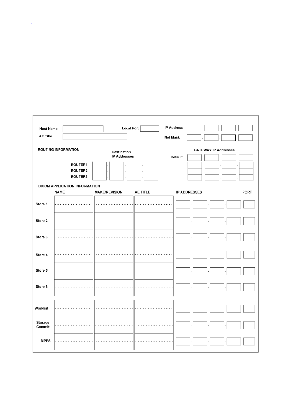
GE CONFIDENTIAL
Facility needs
Entries must include:
• A host name, local port number, AE Title, IP address and
Net Mask for the Ultrasound system.
• The IP addresses for the default gateway and other routers
at the site for ROUTING INFORMATION.
• The host name, IP address, port and AE Title for each
device the site wants connected to the Ultrasound system
for DICOM APPLICATION INFORMATION. A field for the
make (manufacturer) and the revision of the device, is also
included. This information may be useful for error solving.
Figure 2-4. Worksheet for DICOM Network Information
Vivid E80/E90/E95 – Proprietary Service Manual 2-19
GC091999 Rev. 4
Page 90

GE CONFIDENTIAL
Site Preparations
Section 2-4 Environmental Dangers
Commercial devices such as laser cameras, printers, VCRs and external monitors,
usually exceed allowable leakage current limits and, when plugged into separate AC
outlets, are in violation of patient safety standards. Suitable electrical isolation of such
external AC outlets, or providing the device with extra protective earth, will be required
in order to meet UL60601-1 and IEC60601-1 / IEC60601-1-1 standards for electrical
leakage.
2-4-1 Patient Vicinity UL60601-1 (USA)
2.12.20DV (UL60601-1:2003)
In area in which patients are normally cared for, the patient vicinity is the space with
surfaces likely to be contacted by the patient or attendant who can touch the patient.
This encloses a space within the room 1.83 m (6 ft.) beyond the perimeter of the bed
(examination table, dental chair, treatment booth, and the like) in its intended location,
and extending vertically 2.29 m (7.5 ft.) above the floor.
1. Patient environment
2-20 Vivid E80/E90/E95 – Proprietary Service Manual
GC091999
Rev. 4
Page 91

GE CONFIDENTIAL
Environmental Dangers
2-4-2 Patient Environment IEC60601-1 (IEC60601-1-1) and
ANSI AAMI ES60601-1
Sub Clause 2.202 and figure 201 (IEC60601-1-1:2000)
Sub Clause 3.79 and figure A.9 (IEC60601-1:2005 and ANSI AAMI
ES60601-1:2005)
Such an area is an environment in which medical diagnosis, monitoring or treatment is
carried out. It is very difficult to attach unique dimensions to the PATIENT
ENVIROMENT.
In practice, a distance of 2,5 m (8.2 ft.) above the floor on which the medical personnel
stand and a horizontal distance of 1,5 m (4.9 ft.) have justified themselves as
indicative of the dimensions of the Patient Environment.
The patient environment/vicinity will be depicted as a dashed line in this procedure.
See example below.
1. Patient environment
Figure 2-5. Patient environment
Vivid E80/E90/E95 – Proprietary Service Manual 2-21
GC091999 Rev. 4
Page 92

Site Preparations
GE CONFIDENTIAL
THIS PAGE WAS INTENTIONALLY LEFT BLANK
2-22 Vivid E80/E90/E95 – Proprietary Service Manual
GC091999
Rev. 4
Page 93

GE CONFIDENTIAL
System Setup
Chapter 3
This chapter contains information needed to install Vivid
E80/E90/E95.
Included is a procedure that describes how to receive
and unpack the equipment and how to file a damage or
loss claim.
How to prepare the facility and Ultrasound system of the
actual installation, and how to check and test the
Ultrasound system, probes, and external peripherals for
electrical safety are also included in this procedure.
See 3-1-1 ‘Contents in this chapter’ on page 3-2 for
more information.
Vivid E80/E90/E95 – Proprietary Service Manual 3-1
GC091999 Rev. 4
Page 94

GE CONFIDENTIAL
System Setup
3-1-1 Contents in this chapter
• Section 3-1 ‘Overview’ on page 3-2
• Section 3-2 ‘Setup reminders’ on page 3-3
• Section 3-3 ‘Receiving and unpacking the equipment’ on
page 3-5
• Section 3-4 ‘Packing materials - recycling information’ on
page 3-19
• Section 3-5 ‘Preparing for setup’ on page 3-21
• Section 3-6 ‘Completing the setup’ on page 3-22
• Section 3-7 ‘Configuration’ on page 3-30
• Section 3-8 ‘Connectivity overview’ on page 3-50
• Section 3-9 ‘Connectivity setup’ on page 3-52
• Section 3-10 ‘Disk Management setup’ on page 3-86
• Section 3-11 ‘InSite ExC setup’ on page 3-88
• Section 3-12 ‘Options setup’ on page 3-97
• Section 3-13 ‘Paperwork after setup’ on page 3-100
Section 3-1 Overview
3-2 Vivid E80/E90/E95 – Proprietary Service Manual
GC091999
Rev. 4
Page 95

Section 3-2 Setup reminders
DANGER
CAUTION
CAUTION
CAUTION
3-2-1 Average setup time
• Unpacking the Vivid E80/E90/E95: 0.5 hour
• Set up Vivid E80/E90/E95 wo/options: 4 hours or more,
depending on the configuration
• DICOM Network Configuration: 2 hours or more, depending
on the configuration
• Install InSite: 0.5 hour
3-2-2 Setup warnings
GE CONFIDENTIAL
Setup reminders
WHEN USING ANY TEST INSTRUMENT THAT IS CAPABLE
OF OPENING THE AC GROUND LINE (I.E., METER’S
GROUND SWITCH IS OPEN), DON’T TOUCH THE
ULTRASOUND SYSTEM!
To prevent electrical shock, connect the Ultrasound system to a
properly grounded power outlet. Do not use a three to two
prong adapter. This defeats safety grounding.
Do not wear the ESD wrist strap when you work on live circuits
and more than 30 V peak is present.
Do not operate this Ultrasound system unless all board covers
and frame panels are securely in place. System performance
and cooling require this.
Vivid E80/E90/E95 – Proprietary Service Manual 3-3
GC091999 Rev. 4
Page 96

GE CONFIDENTIAL
CAUTION
CAUTION
CAUTION
System Setup
3-2-2 Setup warnings (continued)
If the Ultrasound system is very cold or hot, do not turn on its
power until it has had a chance to acclimate to its operating
environment.
The following table describes guidelines for reaching operational
temperatures from storage or transport temperatures.
Operator Manual(s)
The User Manual(s) should be fully read and understood
before operating the Vivid E80/E90/E95 and kept near the
Ultrasound system for quick reference.
Acoustic Output Hazard
Although the ultrasound energy transmitted from the Vivid E80/
E90/E95 probe is within AIUM/NEMA standards, avoid
unnecessary exposure. ultrasound energy can produce heat
and mechanical damage.
3-4 Vivid E80/E90/E95 – Proprietary Service Manual
GC091999
Rev. 4
Page 97

GE CONFIDENTIAL
CAUTION
Section 3-3 Receiving and
unpacking the equipment
3-3-1 Purpose of this section
This section describes how to receive and unpack Vivid E80/
E90/E95.
3-3-2 Contents in this section
• 3-3-3 ‘Warnings for receiving and unpacking’ on page 3-5
• 3-3-4 ‘The Tilt and Shock indicators’ on page 3-7
• 3-3-5 ‘If Shock Indicator has triggered or is missing’ on
page 3-8
• 3-3-6 ‘If Tilt Indicator has triggered or is missing’ on
page 3-9
• 3-3-7 ‘Position of the Tilt & Shock indicators’ on page 3-10
• 3-3-8 ‘Receiving the Vivid E80/E90/E95’ on page 3-11
• 3-3-9 ‘Unpacking the Vivid E80/E90/E95’ on page 3-14
Receiving and unpacking the equipment
3-3-3 Warnings for receiving and unpacking
Two people are needed to unpack the Ultrasound system
because of its weight. Attempts to move the Ultrasound system
considerable distances or on an incline by one person could
result in injury or damage or both.
Two people are required whenever a part weighing 16 KG (35
LBS) or more must be lifted.
Vivid E80/E90/E95 – Proprietary Service Manual 3-5
GC091999 Rev. 4
Page 98

System Setup
CAUTION
GE CONFIDENTIAL
Remember to use relevant personal protecting equipment
(PPE) during packing and unpacking. Check with your local
EHS representative.
3-6 Vivid E80/E90/E95 – Proprietary Service Manual
GC091999
Rev. 4
Page 99

GE CONFIDENTIAL
Receiving and unpacking the equipment
3-3-4 The Tilt and Shock indicators
3-3-4-1 Overview
Improper handling during transportation may harm the
equipment inside the package even if the package itself is
undamaged.
To make it easier to detect if the handling during transportation
has been improper, a set of Tilt & Shock indicators have been
attached to the transportation box.
Table 3-1: Shock and Tilt Watch
Description Illustration
ShockWatch
Tilt Watch
Vivid E80/E90/E95 – Proprietary Service Manual 3-7
GC091999 Rev. 4
Page 100

GE CONFIDENTIAL
System Setup
3-3-5 If Shock Indicator has triggered or is missing
The purpose of a shock indicator label is NOT to tell whether a
product has been damaged during shipment. The purpose of
these labels is to alert people handling a package that the
product contained is very sensitive to shock damage and that it
should be handled carefully. It is basically an active “Fragile”
label that turns red if a predetermined shock does occur.
Because the labels can receive false activation due to an impact
shock directly on the label, an activated label must not be
interpreted to mean product damage. It simply means that the
receiver should note on the shipping papers at the time of
receipt that the label was activated and the product should be
inspected for possible concealed damage. Conversely, a high
level, product-damaging shock could occur to the package in a
way that does not activate the label, so a non activated label
does not ensure that the product is not damaged. Some degree
of inspection is still required.
Table 3-2: Shock Indicator has triggered or is missing
Step Task
1.
2.
If the Shock Indicator is missing:
Note on the shipping papers at the time of
receipt that the Shock Indicator label is missing.
If the Shock Indicator has triggered:
Note on the shipping papers at the time of
receipt that the Shock Indicator label was
activated.
Inspect the product for possible concealed
damage.
3-8 Vivid E80/E90/E95 – Proprietary Service Manual
GC091999
Rev. 4
 Loading...