

Page 1
GE
g
READ THOROUGHLY BEFORE INSTALLING
Lighting Solutions
WARNING
Risk of electric shock
• Turn power off before servicing
– see instructions
GENERAL
This luminaire is designed for use in outdoor
applications and should not be installed in areas of
limited ventilation or in high ambient temperature
enclosures. This fixture should be installed and maintained according to the following recommendations.
UNPACKING
This luminaire has been packed so that no parts
should have been damaged during transit. Inspect to
confirm.
GEH-3942C
INSTRUCTIONS
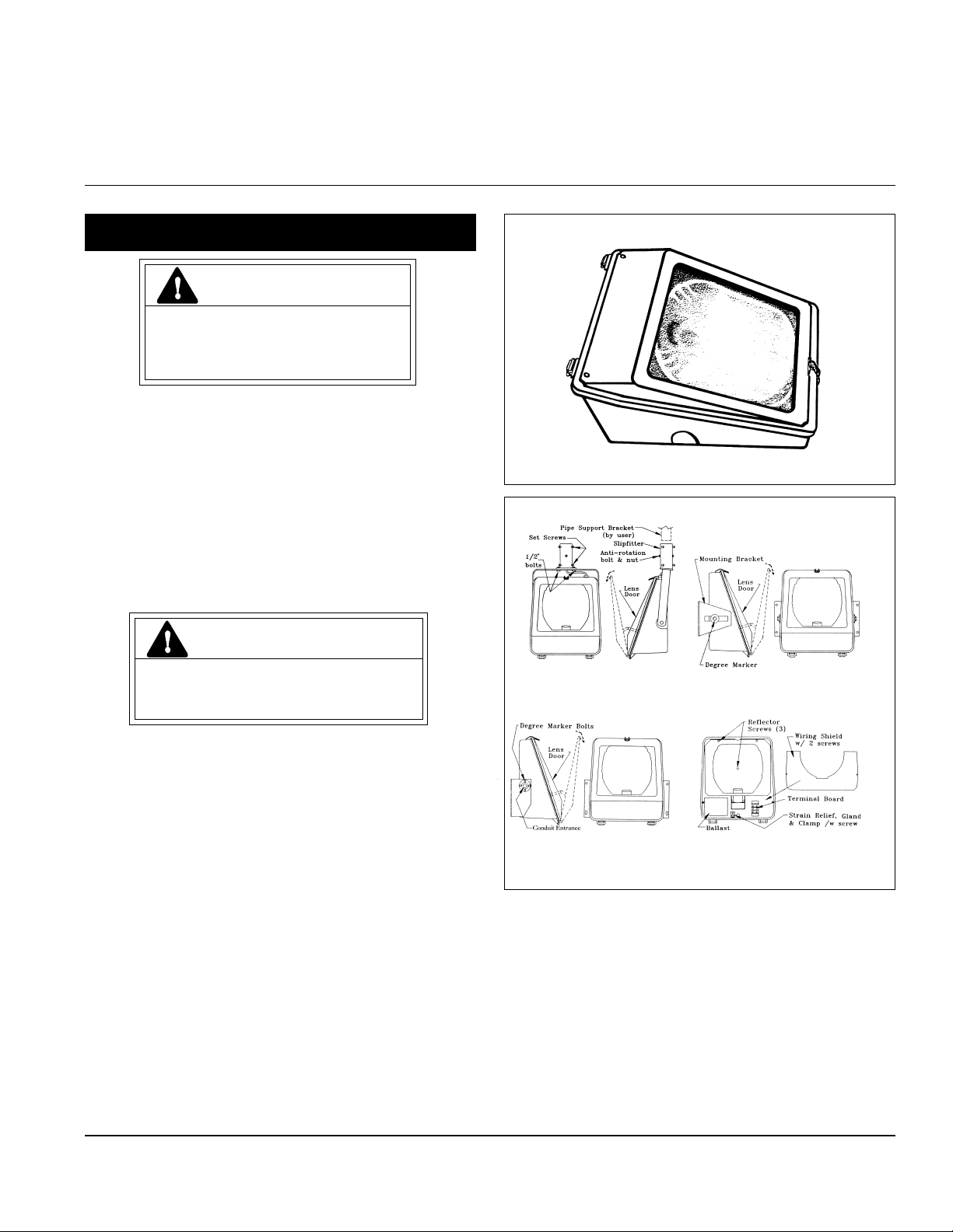
Versaflood ® II Signliter
INSTALLATION
CAUTION
Unit will fall if not installed properly
• Follow installation instructions
CAUTION: For aimed-up application, remove
two screws from rear bottom corners of back
housing, and re-install them in front housing
rear bottom corners.
Luminaires Installed Without Conduit
(Standard mounting)
Type SO (AWG 14-3) cable (normally supplied by
user) is recommended for electrical connections to this
luminaire.
1. Unlatch, open door and remove door assembly.
Remove reflector and shield.
2. Remove (4) knockouts in housing back. Using these
holes install housing to mounting surface with (4)
5/16 inch bolts, nuts and lock washers(*). Seal
around these bolts with appropriate sealing
compound(*).
*(Supplied by user.)
3. If the luminaire is prewired with power supply cable,
proceed to instruction 3a or 3b, otherwise remove the
wiring shield to expose the terminal board (see Figure 4).
Figure 1 Figure 2
Figure 3 Figure 4
Loosen the cable strain relief clamp and insert the
supply cable through the gland from the back 7 to 9
inches. Connect cable leads to the terminal board,
retract cable to a good wire dress and tighten the
strain relief clamp. Refer to the WIRING section of
this instruction. Replace the wiring shield and
reflector and install lamp. Close and latch the lens
door.
3a. Pipe Mounted (See Figure 1)
Mount the trunnion slipfitter on the support pipe
bracket and tighten all six set screws. Mount the
luminaire and trunnion to the slipfitter using the
1/2-inch bolts and nuts provided. Level the
These instructions do not purport to cover all details or variations in equipment nor to provide for every possible contingency to be met in connection with installation, operation
or maintenance. Should further information be desired or should particular problems arise which are not covered sufficiently for the purchaser’s purposes, the matter should be
referred to GE Lighting Solutions.
Page 2
luminaire. Drill a 5/16-inch diameter hole through
the pipe bracket using the through hole in the
slipfitter as a guide. Install the anti-rotation bolt
and nut with the head of the bolt on the top side
of the slipfitter. The power supply cable may now
be fed through the slipfitter and pipe bracket.
3b Bracket Mounted Luminaires. (See Figure 2)
Mount the luminaire on the support structure with
5/16-inch minimum bolts, nuts and lockwashers that
are supplied by the user. Position, aim and tighten
bolts at the degree markers.
MAINTENANCE
CAUTION
Risk of burn
• Allow lamp/fixture to cool before
handling
3/4 INCH CONDUIT MOUNTED LUMINAIRES
(See Figure 3)
1. Mount the luminaire on the support structure with
5/16-inch minimum bolts, nuts and lockwashers that
are supplied by the user.
2. Unlatch and open the lens door. Remove the
reflector that is held by three screws. Remove the
wiring shield that is held by two screws.
3. Install conduit and supply wiring. Dress the wires
to the terminal board so they will not touch the
reflector when reinstalled. Refer to the WIRING
section of this instruction. Replace the wiringshield.
Replace the reflector. Install the lamp. Close and
latch the lens door.
WIRING
Make all electrical connections in accordance with
the National Electrical Code and any applicable local
code requirements.
Verify that supply voltage is correct by comparing it
to nameplate.
Do not remove insulated connectors from wires not
needed for required voltage connection.
When changing voltage on reconnectable units,
move only the lead with the insulated connector.
IF SINGLE VOLTAGE:
All single voltage ballasts are pre-wired such that
user need only connect the supply conductors.
IF MULTIVOLT: (120/208/240/277 volts)
Connect the ballast lead with the insulated terminal
to the desired voltage terminal as indicated on the
ballast terminal nameplate.
IF MULTIWATT:
Multiwatt ballasts are available in various combinations of wattage. See wiring instructions on wiring
tag inside the luminaire.
WARNING
Risk of burn
• Do not touch operating luminaire
It will occasionally be necessary to clean the
outside of the refractor to maintain the light level.
Frequency of cleaning will depend on the ambient dirt
level and the minimum light level which is acceptable
to the user. The lens door should be washed in a
solution of warm water and any mild, non-abrasive
household detergent, rinsed with clean water and
wiped dry. Should the optical assembly become dirty
on the inside, wipe the reflector and clean the lens
door in the above manner and replace any damaged
gaskets.
LAMP INSTALLATION/REPLACEMENT
Use only lamps specified on nameplate. Observe
lamp manufacturer’s recommendations and restric-
tions on lamp operation, particularly ballast type,
burning position, etc.
The light output of a luminaire is also dependent on
the age of the lamp. In applications where the light
level is critical it may be desirable to replace lamps
before they reach end of life. The lamp manufacturer
can provide data showing how the lamp light output
decreases with use.
Lamp Tightness – Mogul Base Lamp: The lamp
should be securely inserted to the NEMA-EEI specified
torque of 35 inch-pounds, which is best achieved by
very firmly tightening to insure application of sufficient
torque. Tightening must be sufficient to fully depress
and load the center contact of the socket.
Lamp Tightness – Medium Base Lamp: The lamp
should be tightened to a light firmness sufficient to
depress the center contact.
FINAL ASSEMBLY
Photoelectric Control:
The photoelectric control receptacle (if present)
should be oriented before the control is installed.
Loosen the two screws and rotate the receptacle to
the desired direction. Retighten the screws and install
control.
GE Lighting Solutions • 1-888-MY-GE-LED • www.gelightingsolutions.com
16943533----888
GE Lighting Solutions is a subsidiary of the General Electric Company. Evolve and other trademarks belong to GE Lighting Solutions. The GE brand and logo are trademarks of the General Electric Company.
© 2011 GE Lighting Solutions. Information provided is subject to change without notice. All values are design or typical values when measured under laboratory conditions.
g
35-201578-N4 6/00
 Loading...