

Page 1

Autotrol
Series 255 Valve
Series 263 Valve
Series 268 Valve
740C-ET & 760C-ET
Controllers
Quick Start Manual
Page 2
LOGIX™ SERIES INSTALLER QUICK-START SHEET
LOGIX SERIES CONTROLLERS
740 Controller - Electronic time clock control capable of doing 7-day (day of
week) regeneration, or up to a 99 interval day regeneration. This control will
operate both in a conditioner (softener) or 3-cycle filter mode with the same
controller.
760 Controller - Electronic metered-demand (volumetric) controller which
regenerates based on the water usag e of the installation site. A calendar
override is a standard feature on this controller.
The Logix Series will operate on both the 255 and Performa valve body series.
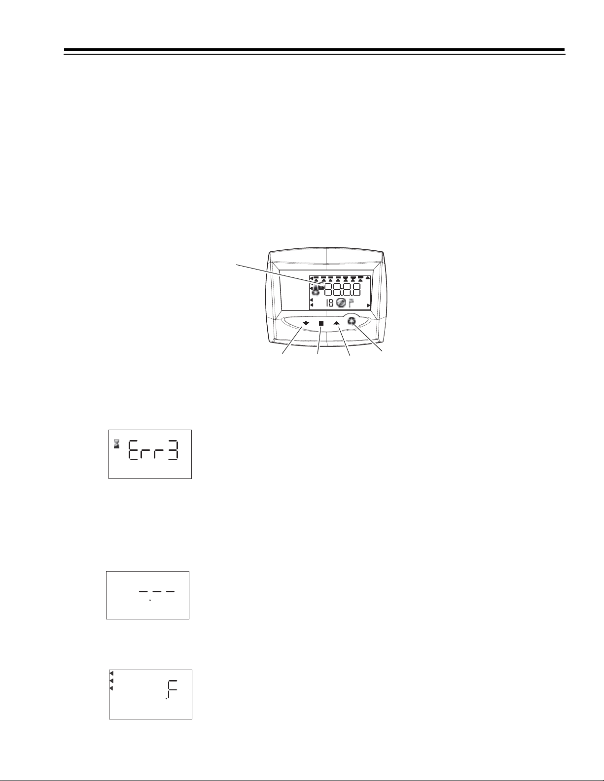
LCD Display
SU MO TU WE TH FR SA DAYS
Time & Day
Regen Time & Day
Salt
x2
Capacity
P
Hardness
H
C
DOWN Button
SET Button
INITIAL POWER-UP
Initial Power Up - (CAMSHAFT proceeds to HOME position)
• At initial power-up, the camshaft will need to rotate to the HOME
(in service) position.
• Camshaft may take 1-2 minutes to return to home position.
• Err 3 will be displayed until the camshaft returns to home.
• If more than 2 minutes elapses, verify that the motor is turning the
camshaft. If it is not turning, see the troubleshooting section in Dealer
Installation and Service Manual.
Time & Day
Regen Time & Day
Capacity
Hardness
SU MO TU WE TH FR SA DAYS
Salt
INITIAL START-UP STEP-BY-STEP INSTRUCTIONS
PM
MIN
LBS
KG
x100
UP Button
Manual Regeneration
Time & Day
Regen Time & Day
Salt
Capacity
Hardness
Time & Day
Regen Time & Day
Capacity
Hardness
SU MO TU WE TH FR SA DAYS
SU MO TU WE TH FR SA DAYS
Salt
Step 1: Program System Size
This step may have been performed by your system’s OEM manufacturer. In
this case, proceed to step 2
• Input tank diameter size in inch (7-8-9-10-11-12-13-14-16).
• Use UP and DOWN buttons to scroll diameter choices.
• "11" value corresponds to 10x44 and 10x54 tank sizes.
• To choose a 3-cycle filter operation - press DOWN until an "F" is displayed.
• Press SET to accept the system size you’ve selected.
• If incorrect setting is programmed, see "Resetting the Control" section
below.
.
1
Page 3
SU MO TU WE TH FR SA DAYS
Time & Day
Capacity
Hardness
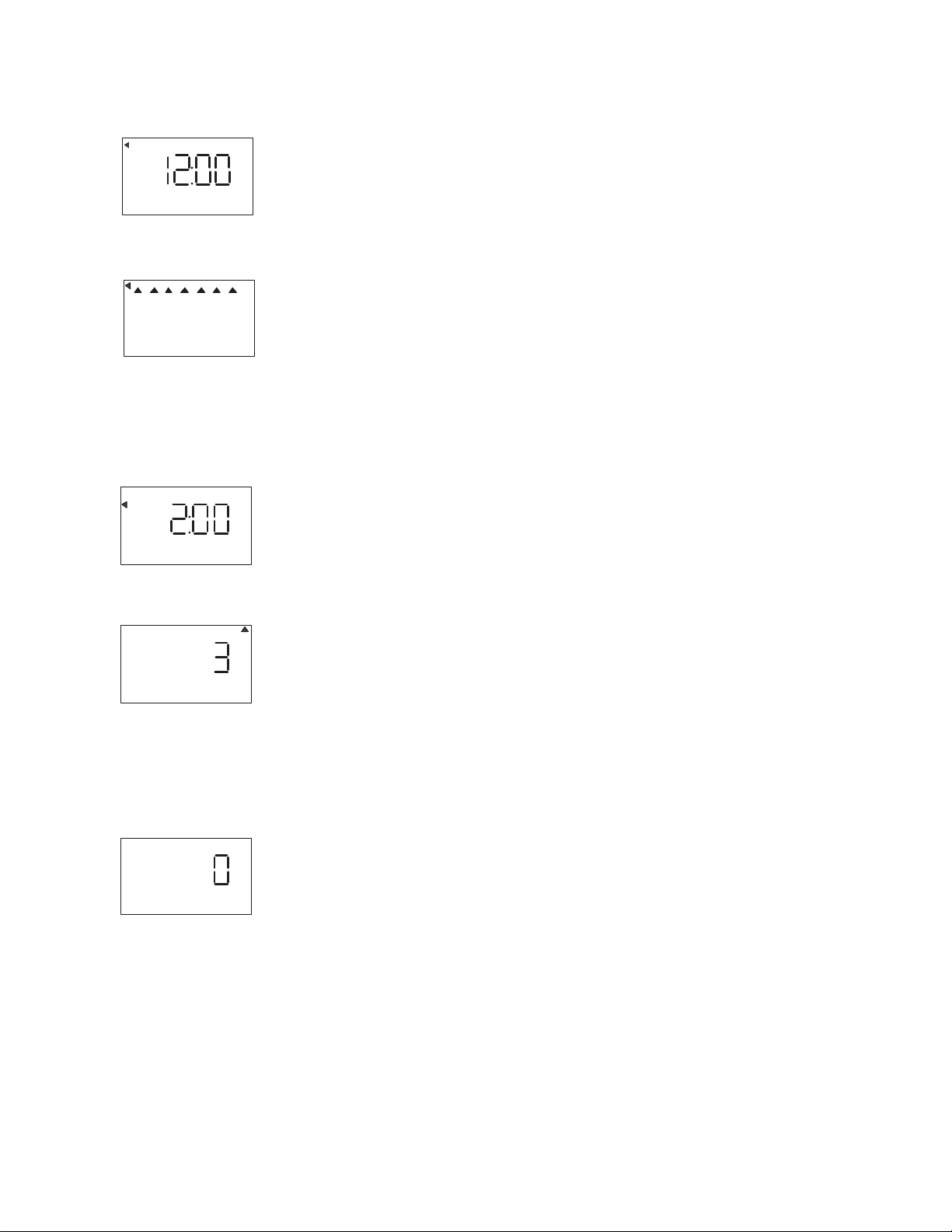
Step 2: Program Time of Day
• While "12:00" is blinking, set the correct time of day.
• Use the UP and DOWN buttons to scroll to the correct time of day.
• "PM" is indicated, "AM" is not indicated.
• Press SET to accept the correct time of day and advance to the next parameter.
Step 3: Set Day of Week
Time & Day
Regen Time & Day
Capacity
Hardness
Time & Day
Regen Time & Day
Salt
Capacity
Hardness
Time & Day
Regen Time & Day
Salt
Capacity
Hardness
SU MO TU WE THFRSA DAYS
Salt
SU MO TU WE TH FR SA DAYS
SU MO TU WE TH FR SA DAYS
• Press SET to make the arrow under SU flash.
• Use the UP and DOWN butt ons to advance th e arrow until it is under the co rrect da y of
week.
• Press SET to accept and advance to the next parameter.
After steps 1-3, the controll er will operate most syste ms. Proce ed to step 4 if further
adjustments to your system’s programming is needed.
To exit the programming state, wait 30 seconds and the controller will automatically put
you into the normal operating mode.
Step 4: Set Regen Time
• 2:00 (AM) is the default time of regeneration. To accept this time, press the DOWN
button to move to step 5.
• To change the regen time, press SET - causing 2: 00 to flash.
• Use the UP and DOWN buttons to advance to the desired regen time.
• Press SET to accept the time and advance to the next parameter.
Step 5: Set Days to Regenerate (740 Time-clock Control Only)
• If using 760 control - proceed to step 5b
• Set number of da ys between time-clock regeneration (regen fr equency).
• Default time is 3 days.
• Days can be adjusted from 1/2 (.5) to 99 days.
• To change, press SET to make the "3" flash.
• Use the UP and DOWN but tons to change to the number of days desired.
• Press SET to accept the regen frequency, and advance to the next cycle.
To use the 7-day timer option - see full Dealer Installation Manual.
Time & Day
Regen Time & Day
Salt
Capacity
Hardness
2
SU MO TU WE TH FR SA DAYS
Step 5a: Regeneration in a specific day of week (7 days timer)
• To set the regeneration in specific days, set "0" in calendar override.
• Done this, the arrow in the left side of the display indicates hour/ regeneration day.
• Press SET button and a flashing cursor will be displayed at the top under Sunday.
• The day of the week can be adjusted when the cursor at desired position.
• To select or delete the day of week, the triangular cursor has to be under this day.
• If the cursor is in position but fixed, press SET button to make it flashing.
• To move the cursor when is fixed use UP and DOWN buttons, press SET if is flashing.
Page 4

Example: To move the cursor and select/deactivate a day
1. The cursor should be fixed. If is flashing, press SET.
2. Use UP and DOWN buttons to put the cursor under the day to change.
3. Press SET button. The cursor will flash.
4. Use UP and DOWN buttons to activate the flag for the desired day.
5. Press SET to move the cursor to the following day. The cursor will be fixed.
When the cursor will be under S (Saturday) and will flashing, press SET and the week
days programming will be completed. The menu will move up to the salt amount
c hoice.
To return to regeneration frequency, the days selected for the regeneration have to be
deactivated. The values related to the days between two following regenerations could be
not equal to zero.
Step 5b: Set Calendar Override (760 Demand Control Only)
Time & Day
Regen Time & Day
Salt
Capacity
Hardness
SU MO TU WE TH FR SA DAYS
• If using 740 control - proceed to step 6.
• Set number of days for calendar override on demand control
• "0" days is the default for calendar override.
• Days can be adjusted from 1/2 (0.5) to 99 days.
• To change, press SET to make the "0" flash.
• Use the UP and DOWN buttons to change to the number of days desired.
• Press SET to accept the regeneration frequency and to advance to the next cycle.
3
Page 5

SU MO TU WE TH FR SA DAYS
Time & Day
Regen Time & Day
Salt
Capacity
Hardness
Standard Salt Setting
SU MO TU WE TH FR SA DAYS
Time & Day
Regen Time & Day
Salt
Capacity
Hardness
High Salt Setting
SU MO TU WE TH FR SA DAYS
Time & Day
Regen Time & Day
Salt
Capacity
Hardness
Low Salt Setting
Step 6: Set Salt Amount (Regenerant Amount)
• Set desired salt amount.
• Default setting is "S" standard salting.
• 3 salt settings are av ailable on 740 and 760 controls:
S - Standard Salt
H - High Salt
L - Low Salt
• Low Salt is the "Highly Efficient Mode".
• To change salt setting, press the SET button an d use the UP and DOWN buttons to
change to the desired setting.
• Press SET to accept the setting and advance to next parameter.
Step 7: Estimated Capacity
• System capacity is displayed in total kilograms of CaCO3 removed
before a regeneration is necessary.
• Value is derived from the system’s size input, and L-S-H salt amount input.
• The capacity displayed is a suggested value.
Time & Day
Regen Time & Day
Capacity
Hardness
SU MO TU WE TH FR SA DAYS
Salt
KG
• Capacity is only displayed for information purposes on 740 control - it does not (and
cannot) need to be changed.
• To change capacity on 760 control, press SET to make the default capacity flash. Use
the UP and DOWN buttons to increment to the desired capacity.
• Press SET to accept the setting and advance to the next parameter.
If using 740 control, programming is complete. The control will return you to the normal
operation mode.
Step 8: Enter Hardness (760 Demand Control Only)
• Enter inlet water hardness at installation site.
• Default hardness setting is 10 ppm (1° F)
• To change hardness value, press SET to make the setting flash. Use the UP and DOWN
buttons to scroll to the correct hardness.
• Press SET to accept the entered hardness value.
• The control will return you to the normal operation mode.
In case of 760 F filter controller, instead insert Hardness value, set work volume cycle (m3)
divided by 10.
NOTE: In case of fixed displying of "1.01-1.02-1.03" values, blow into turbine for some seconds in order to unblock
the controller.
4
Page 6

MANUAL REGENERATION PROCEDURES
To Initiate a Manual Regeneration:
• Press REGEN once for delayed regeneration.
System will regenerate at next set regen time (2:00 AM).
A flashing regen (recycle) symbol will be displayed.
• Press and hold REGEN for 5 seconds to initiate immediate manual regeneration. A
solid regen symbol will be displayed.
• After immediate regeneration has begun, press REGEN again to init iate a second
manual regeneration. An X2 symbol will be displayed, indicating a second
regeneration will follow the first regeneration.
SU MO TU WE TH FR SA DAYS
Time & Day
Regen Time & Day
Salt
Capacity
Hardness
C
Regen Symbol
Cycle Indicator
MIN
During a Regeneration:
• A "C#" is displayed to show current cycle.
• Total regen time remaining is displayed on screen.
• Press and hold SET to show current cycle time remaining.
To Advance Regeneration Cycles:
• Press and hold SET - showing current cycle time.
• Simultaneously press SET and UP to advance cycle.
An hourglass will display while cam is advancing.
When cam reaches next cycle, "C2" will be displayed.
• Repeat SET and UP to advance through each cycle.
• Press and hold SET and UP buttons for 5 seconds to cancel regen.
Hourglass will flash once cancelled.
Camshaft will advance to home - may take 1-2 minutes.
Regeneration Cycles:
•C1 - Backwash
• C2 - Regenerant Draw/Slow Rinse (not used in filter mode)
• C3 - Slow Rinse (not used in filter mode)
• C4 - System Pause (to repressurize tank)
• C5 - Fast rinse cycle 1
• C6 - Backwash cycle 2 (not used in filter mode)
• C7 - Fast Rinse cycle 2 (not used in filter mode)
• C8 - Regenerant refill (not used in filter mode)
RESETTING THE CONTROL
SU MO TU WE TH FR SA DAYS
Time & Day
Regen Time & Day
Salt
Capacity
H
Hardness
Resetting the Logix Controller
SU MO TU WE TH FR SA DAYS
Time & Day
Regen Time & Day
Salt
Capacity
Hardness
Unprogrammed control after reset
WARNING: Resetting the contr ol will delete all information stored in its memory. This will require you to
reprogram the control completely from the initial power up mode.
All further informations about performances will be available on OEM Installation and Service Manual.
5
To reset the control:
1. Press and hold SET and DOWN simultaneously for 5 seconds.
2. H0 and the system’s set resin volume (or "F" mode) will be displayed.
3. If a history value other than "H0" is displayed, use the up arrow to scroll through the
settings until "H0" is displayed.
4. To reset the control, press and hold SET for 5 seconds.
5. The control will be reset to an unprogrammed state.
6. Go to "Initial Set-up" section of this sheet to reprogram control.
Page 7

Logix™ Chlorine Generator (Check Salt Light)
The Logix 740C/742C and 760C/762C controls
have the capability to command a device
for chlorine production (optional) to disinfect the
resin bed at every regeneration.
There is a check salt light which indicates
when the salt finishes.
Potassium chloride or sodium
chloride may be used. Installing the chlorine
generator is simple.
Step 1
Remove the Logix control from the valve and
disconnect power.
Step 2
Connect the chord to the plug
on the back of the Logix control
at the connection labeled "Chlorine Generator
Outlet 740C/742C and 760C/762C."
Installation Instructions
Chlorine Generator Outlet (740C/742C and 760C/762C versions)
Back of Logix Control
Refill Controller
Check Salt Light
Step 3
Remove the existing refill controller
from the valve and replace it with the chlorine
generator refill flow control. See the illustrations
to the right for the location of the refill controller.
Step 4
Insert the large connector of the chlorine
generator chord to the end of the refill flow
control. Press it in firmly to make sure there is
good contact.
Step 5
Reconnect power to the Logix Control and
reinstall the control to the valve.
No programming is necessary for the chlorine
generator to work properly. After the chlorine
generator senses regenerant for the first time it
will be functional. There is a check salt light on
the front of the Logix control that will illuminate
when there is no regenerant present during the
regenerant draw.
Injector and Cap
255 Valve Identification
Check Salt Light
Injector and cap
Refill Controller
Performa Valve Identification
© Copyright 2004 GE Osmonics
Printed in USA P/N 1244339 Rev A
Page 8

Logix 740/760 Programming Table (7-11)
(
)
PROGRAM
Salt Amount
Setting
Capacity
(kg CaCO
Salt Amount
Resin Volume
Valve Model
Injector Type
Backwash
I° backwash
C1 (min)
Brine Draw +
slow rinse C2
Pressurization
C4 (min)
)
3
(kg)
Tank
Size
(liters)
min
L
low
9x17
# 9
S
medium
9x35
255/268
G
09
8
1
H
alto
9x42
# 7
L
medium
low
0,3 0,4 0,9 0,4 0,5 1,1 0,6 1,3 1,7 0,7 1,5 1,6 2 2,5 2,7
0,9 1,1 2,5 1,1 1,4 3,2 1,8 3,6 4,5 1,8 4,3 5,7 5,9 7,3 9,5
7x13
5,57 166,59 20112432132828384747
255
07
37,5 48,5 104,5 32 42 96,5 38,5 83,5 109 32,5 73,5 79,5 86,5 107 116
H
S
high
7x17
7x35
E
8
1
L
low
8x13
# 8
S
medium
8x17
255
F
08
8
1
H
alto
8x35
L
low
10x17
# 10
S
medium
10x35
255/268
H
10
8
1
H
alto
10x35
L
low
10x44
# 11
S
medium
10x54
255/268
J
10
8
1
H
alto
10x54
I° fast rinse
C5 (min)
II° backwash
C6 (min)
II° fast rinse
C7 (min)
Refill C8 (min) 2 2,5 5,5 2,5 3 7 4 8 10 4 9,5 12,5 13 16 21
Regeneration
total time (min)
* Minimum regeneration pressure: 2 bar
53,5 65 124 48,5 59 117,5 56,5 105,5 133 50,5 97 106 114,5 138 152
3
1
1
3
1
1
3
1
1
3
1
1
4
1
1
Page 9

Logix 740/760 Programming Table (12-F)
(
)
PROGRAM
Salt Amount
Setting
Capacity
(kg CaCO
Salt Amount
Resin Volume
Valve Model
Injector Type
Backwash
I° backwash
C1 (min)
Brine Draw +
slow rinse C2
Pressurization
C4 (min)
)
3
(kg)
Tank
Size
(liters)
min
L
low
14x65
# 14
S
medium
14x65
268
M
14
10
1
H
high
14x65
# 12
L
medium
low
3,2 3,5 3,8 3,5 4,1 4,4 4,6 5,4 5,8 5,8 6,8 7,3
9,1 9,7 13,1 9,7 11,3 15,0 12,0 15,0 20,0 15,4 19,0 25,0
12x48
60 65 65 65 75 75 100 100 100 125 125 125
255/268
12
88 95 104,5 67,5 78 86 86 92 101,5 84 90 100
H
S
high
12x52
12x52
K
8
1
L
low
13x44
# 13
S
medium
13x54
255/268
L
13
10
1
H
high
13x54
L
low
16x65
# 16
S
medium
16x65
268
N
external
10
1
H
high
16x65
F
φ 7" ÷ 18"
253/263
/
/
1 ÷ 99
/
1
I° fast rinse
C5 (min)
II° backwash
C6 (min)
II° fast rinse
C7 (min)
Refill C8 (min) 20 21,5 29 21,5 25 33 26,5 33 44 34 42 55
Regeneration
total time (min)
* Minimum regeneration pressure: 2 bar
123 131,5 148,5 108 122 138 131,5 144 164,5 139 153 176
4
1
1
6
1
1
6
1
1
8
1
1
10
1
1
/
/
 Loading...