

Page 1

Disposall
®
Food Waste Disposer
ge.com
Owner’s Manual
& Installation
Instructions
165D4700P328 49-55008 12-05 JR
Safety Instructions
Connecting Electricity . . . . . . . . 2, 3
Safety Precautions . . . . . . . . . . . . . 2
Installation Instructions
Attaching the
Discharge Elbow . . . . . . . . . . . . . . . 6
Components and Installation
of Sink Flange . . . . . . . . . . . . . . . . . 5
Connecting Disposer
to Sink Flange . . . . . . . . . . . . . . . . . .7
Dimensions/Typical
Installations . . . . . . . . . . . . . . . . . . . .8
Dishwasher Connection . . . . . . . . 6
Operating Instructions
Batch Feed Models . . . . . . . . . . . . .9
Care and Maintenance . . . . . . . .10
Continuous Feed Models . . . . . . . .9
Troubleshooting Tips
Before You Call for Service . . . . . .11
Consumer Support
Warranty . . . . . . . . . . . . . . . . . . . . 12
Write the model and serial
numbers for your disposall here:
Model # ____________________
Serial #______________________
You can find them on a label on
the bottom of the disposer.
Model Line Series
GFC320
GFC520
GFC530
GFC720
GFC1020
GFB760
Page 2
WARNING!
When using electrical appliances, basic safety precautions should be followed, including the following:
SAFETY PRECAUTIONS
■
■ Use this appliance only for its intended purpose
as described in this Owner’s Manual.
■
■ Read all the instructions before using the
appliance.
■
■ To reduce the risk of injury, close supervision
is required when an appliance is used near
children.
■
■ Do not put fingers or hands into a waste
disposer.
■
■ Turn the power switch (normally a wall switch)
to the off position before attempting to clear
a jam or remove an object from the disposer.
■
■ When attempting to loosen a jam in a waste
disposer, use a long wooden object such as
a wooden spoon or the wooden handle of
a broom or mop.
■
■ When attempting to remove objects from
a waste disposer, only use long-handled,
non-magnetic tools or utensils, since the
disposer may be actuated magnetically.
■
■ To reduce the risk of injury by materials that may
be expelled by a waste disposer, do not put the
following into a disposer:
a) Clam or oyster shells.
b) Caustic drain cleaners or similar products.
c) Glass, china or plastic.
d) Large whole bones.
e) Metal, such as bottle caps, tin cans, utensils
or aluminum foil.
f) Hot grease or other hot liquids.
g) Whole corn husks.
■
■ When not operating a disposer, leave the drain
stopper in place to reduce the risk of objects
falling into the disposer.
■
■ For proper grounding instructions, see the
ELECTRICAL CONNECTION portion of this manual.
2
IMPORTANT SAFETY INSTRUCTIONS.
READ ALL INSTRUCTIONS BEFORE USING.
WARNING!
HOW TO CONNECT ELECTRICITY
If you are not familiar with electrical power and procedures, call a qualified electrician.
DANGER: Improper connection of the equipment-
grounding conductor can result in a risk of electric shock. Check
with a qualified electrician or serviceman if you are in doubt as
to whether the appliance is properly grounded. Do not modify
the plug provided with the appliance if it will not fit the outlet;
have a proper outlet installed by a qualified electrician.
For Models Equipped with a Grounded Cord:
GROUNDING INSTRUCTIONS: This appliance must
be grounded. In the event of a malfunction or
breakdown, grounding provides a path of least
resistance for electric current to reduce the risk of
electric shock. This appliance is equipped with a
cord having an equipment-grounding conductor
and a grounding plug. The plug must be plugged
into an appropriate outlet that is properly installed
and grounded in accordance with all local codes
and ordinances. Most houses have electrical outlets
under the sink that are half-hot. This means one
outlet is controlled by the wall switch, while the
other is always hot. The batch-feed or “TC” model
connects to the hot side, while the continuous feed
model connects to the switch side.
INSTRUCTIONS PERTAINING TO A RISK OF FIRE, ELECTRIC SHOCK OR
INJURY TO PERSONS
Page 3
The power cord and/or connections must comply
with the National Electrical Code, Section 422
and/or local codes and ordinances.
For Models Not Equipped with a Cord:
If your disposer does not come equipped with a cord,
you can connect it in two ways:
1. Attach a power cord, minimum 18″ in length and
not to exceed 36″ in length. GE Kit #PM3X115
provides the parts needed to make this connection.
or
2. Wire the disposer directly into the house current.
GE recommends that a qualified electrician make
this connection.
To Attach a Power Cord:
GROUNDING INSTRUCTIONS: This appliance must be
grounded. In the event of malfunction or breakdown,
grounding provides a path of least resistance for
electric current to reduce the risk of electric shock.
The power cord (to be installed) must have an
equipment-grounding conductor and a grounding
plug. The plug must be plugged into an appropriate
outlet that is properly installed and grounded in
accordance with all local codes and ordinances.
In the absence of local codes and/or ordinances,
the outlet must comply with NEC requirements.
DANGER: Improper connection of the equipment-
grounding conductor can result in a risk of electric shock.
Check with a qualified electrician or serviceman if you are
in doubt as to whether the appliance is properly grounded.
NOTE: Disconnect electric power to disposer circuit before
installation. Turn the circuit breaker to the OFF position or
remove the fuse.
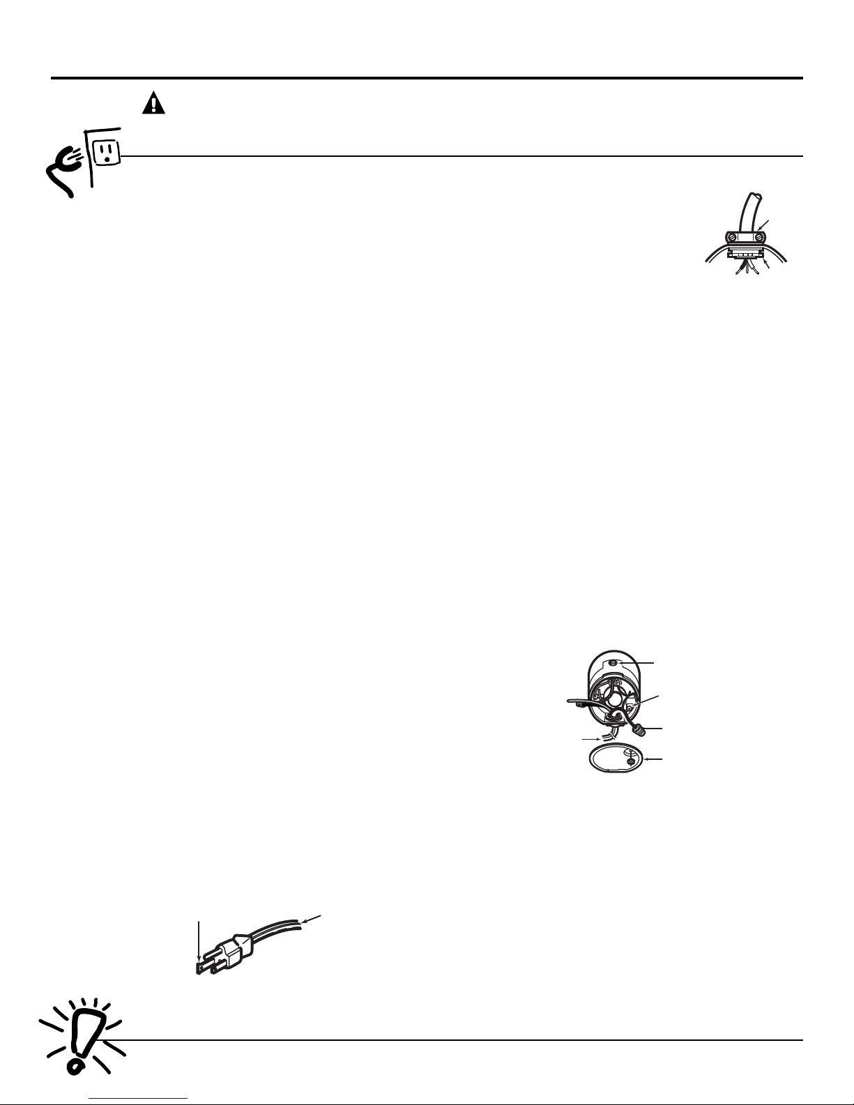
A. Connect the disposer to 110–120 Volt, 60 Hz AC
current only.
B. If a plug-in cord is used, use a three-prong
plug. Ground wire should be attached to the
ground screw in the bottom of the disposer
(end bell).
C.
Use a cable clamp strain relief
connector where power cord
enters the disposer.
To Wire Your Disposer Directly into
the House Current:
GE recommends that a qualified
electrician make this connection.
GROUNDING INSTRUCTIONS:
This appliance must be
connected to a grounded, metal, permanent wiring
system; or an equipment-grounding conductor must
be run with the circuit conductors and connected
to the equipment-grounding terminal or lead on
the appliance.
DANGER: Improper connection of the equipment-
grounding conductor can result in a risk of electric shock.
Check with a qualified electrician or serviceman if you are
in doubt as to whether the appliance is properly grounded.
A. If you use BX cable:
1. Install the cable connector in the hole.
2. Connect white wire to white lead of disposer.
3. Connect black wire.
4. Connect bare ground wire.
If BX cable is not used, provide a separate ground
wire to the nearest grounded connection, using the
screw in the end bell for the ground wire.
B. If your power supply does not include a ground wire,
you must provide one unless metal cable is used.
Attach a copper wire securely to disposer ground
screw and attach other end of wire to the nearest
grounded connection. Use only UL approved ground
clamp. If plastic pipe is used in your home, a qualified
electrician should install a proper ground.
Most houses
have electrical outlets under the sink that are halfhot. This means one outlet is controlled by the wall
switch, while the other is always hot. The batch-feed
or “TC” model connects to the hot side, while the
continuous feed model connects to the switch side.
Trace lead connected to this
blade and attach that lead
to white wire on disposer.
Ribbed
Side
NOTE: When viewing face of electrical plug
with grounding pin at top, the larger left blade
is connected to the identified wire.
READ AND FOLLOW THIS SAFETY INFORMATION CAREFULLY.
SAVE THESE INSTRUCTIONS
3
ge.com
Strain
Relief
Nut
Red Reset Button
Ground Screw
Wire Nuts
Remove
Cover Plate
To House Current
or Power Cord
WARNING!
HOW TO CONNECT ELECTRICITY (cont.)
If you are not familiar with electrical power and procedures, call a qualified electrician.
Bottom of the Disposer (end bell)
Page 4
ADDITIONAL MATERIALS YOU MAY NEED
• Steel punch or wooden dowel
• Petroleum jelly or liquid soap
• Hose clamp
• Dishwasher drain connector
• Adjustable pipe wrench
• Plumber’s putty (for cast sinks)
• Stepped rubber drain adapter
• Wire nuts
• Cable connector
• Flexible drain pipe
• Power cord kit (Part Number PM3X215GDS)
4
BEFORE YOU BEGIN
Read these instructions completely and carefully.
•
IMPORTANT – Save these
instructions for local inspector’s use.
•
IMPORTANT – Observe all
governing codes and ordinances.
• Note to Installer – Be sure to leave these
instructions with the Consumer.
• Note to Consumer – Keep these instructions
for future reference.
• Skill level – Installation of this appliance requires
basic mechanical skills.
• Completion time – 1 hour
• Proper installation is the responsibility of the
installer.
• Product failure due to improper installation is not
covered under the Warranty.
If you have questions, call 800.GE.CARES (800.432.2737) or Visit our Website at: ge.com
Installation
Disposer
Instructions
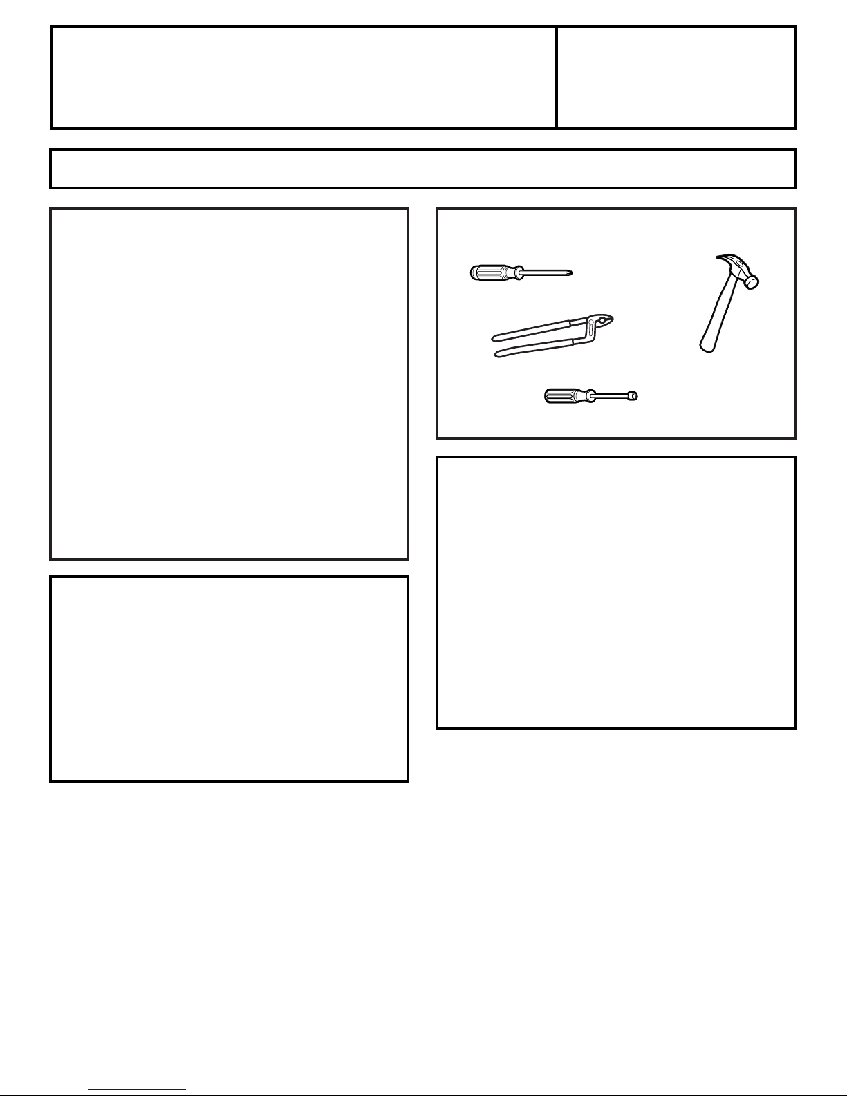
WHAT YOU WILL NEED
• Phillips and flat blade screwdrivers
• Channel lock pliers, slip joint • Hammer
• Nut driver
PREPARATION
1. Disconnect electrical power supply to disposer.
2. Remove old disposer or sink flange assembly.
3. Inspect drain line. If it is heavily coated with hardened
grease and accumulations, rout out with a plumber’s
snake.
4. Remove old sealing materials and gasketing from sink
opening, both top and bottom.
NOTE: Top and bottom of sink surfaces must be free
of any materials to prevent leaks.
Page 5
NOTE: Pay close attention to the order of the sink
flange parts, as they have been correctly assembled
by the factory.
A. Disassemble the sink flange assembly from the
disposer by turning the mount ring to the left
(clockwise) and removing it.
B. Raise the mount ring toward the top of the sink
flange. Remove the cushion mount and the mount
ring. You may want to practice installing the
cushion mount at this point before you are under
the sink.
C. Unscrew the support ring from the sink flange and
remove the fiber gasket. You are now left with the
sink flange and the rubber gasket.
D. The rubber gasket is used instead of plumbers
putty with stainless steel sinks.
E. If no putty is used, insert the sink flange through
the rubber gasket into the sink opening. Do not
turn the flange once it is seated.
F. If you use putty instead of the gasket, form a ring
around the underside of the sink flange. Insert the
flange into the sink opening, press down hard to
squeeze out excess putty. From under the sink,
trim off excess putty flush with the bottom edge
of the sink opening. Use putty sparingly on cast
iron sinks.
G.From underneath the sink,
slip the fiber gasket onto the
exposed sink flange. With
arrows pointing up, screw the
support ring onto the sink
flange and hand tighten until
the sink flange will not move. At
this point you may want to insert the stopper
in the sink and fill with water to check the sink
flange seal and insure there are no leaks.
H.Place the mount ring over
the sink flange and hold in
place while installing the
cushion mount (large side
down). Make sure the
groove on the inside of the
cushion mount fits over the
lip on the sink flange,
similar to putting the lid
on a plastic container.
Run your fingers
around the entire
cushion mount with
slight pressure. Do not press too hard. When the
cushion mount is properly seated, the mount ring
can be pulled downward over the cushion mount
and will be free to turn.
5
Installation Instructions
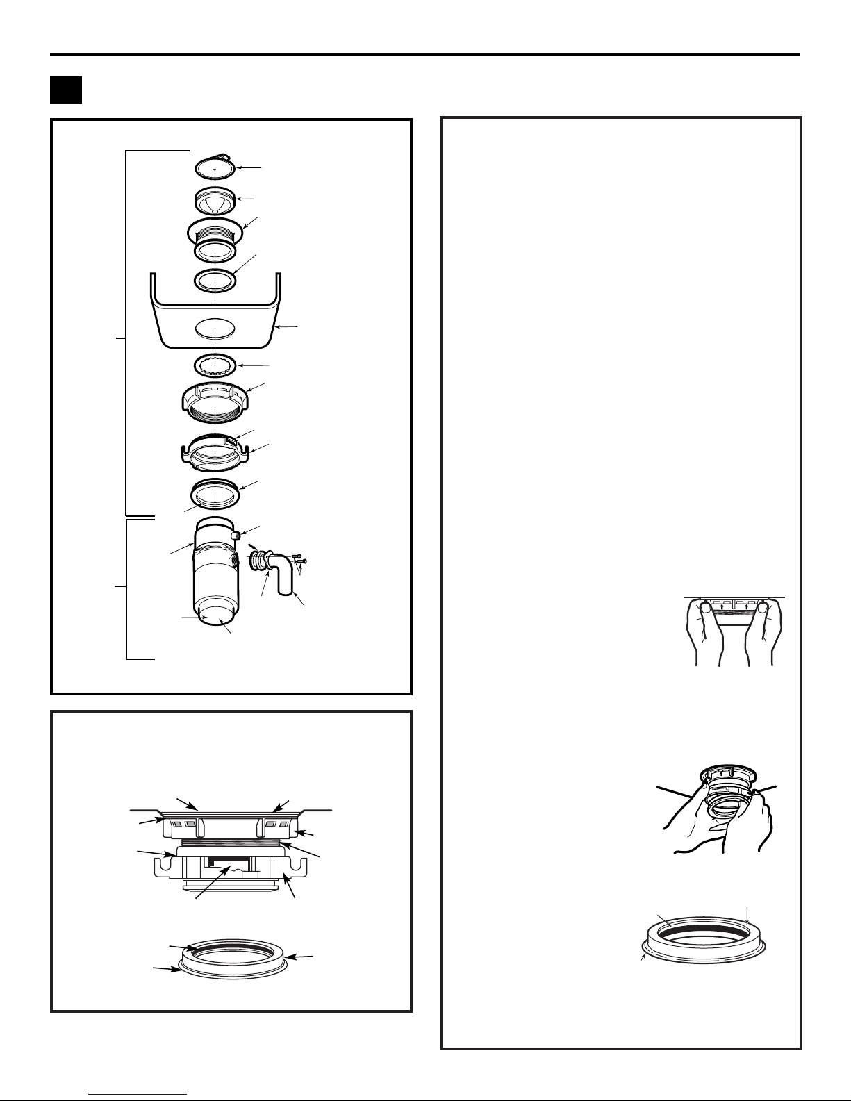
COMPONENTS AND INSTALLATION
1
COMPONENTS
INSTALLATION OF SINK FLANGE
(Read completely before starting.)
Groove
Top
Bottom
Bead
Sink Flange
Rubber Gasket
Sink
Fiber Gasket
Support Ring
Open Area No Obstruction
Sink Flange
Mount Ring should be free
to move up and down
Cushion Mount Detail
*Stopper
*Removable
Splash Guard
Sink Flange
Rubber Sink
Flange Gasket
Groove
Dishwasher
Discharge Inlet
Elbow Gasket
Hopper
Sink
Fiber Gasket
Support Ring
(Note Arrows
Indicating Up)
Screws
Discharge
Elbow
Elbow
Flange
Mount Ring
Rating Label
in This Area
Tightening Ears
End Bell
(Electrical
Connections)
Cushion Mount
*Not used with batch feed model
Sink Flange
Assembly
Disposer
Hand-tighten sink
flange
Correctly Installed Sink Flange
Bottom Bead of
Cushion Mount
Cushion Mount
Groove
Bottom Bead
(shown for proper orientation)
Page 6
6
Installation Instructions
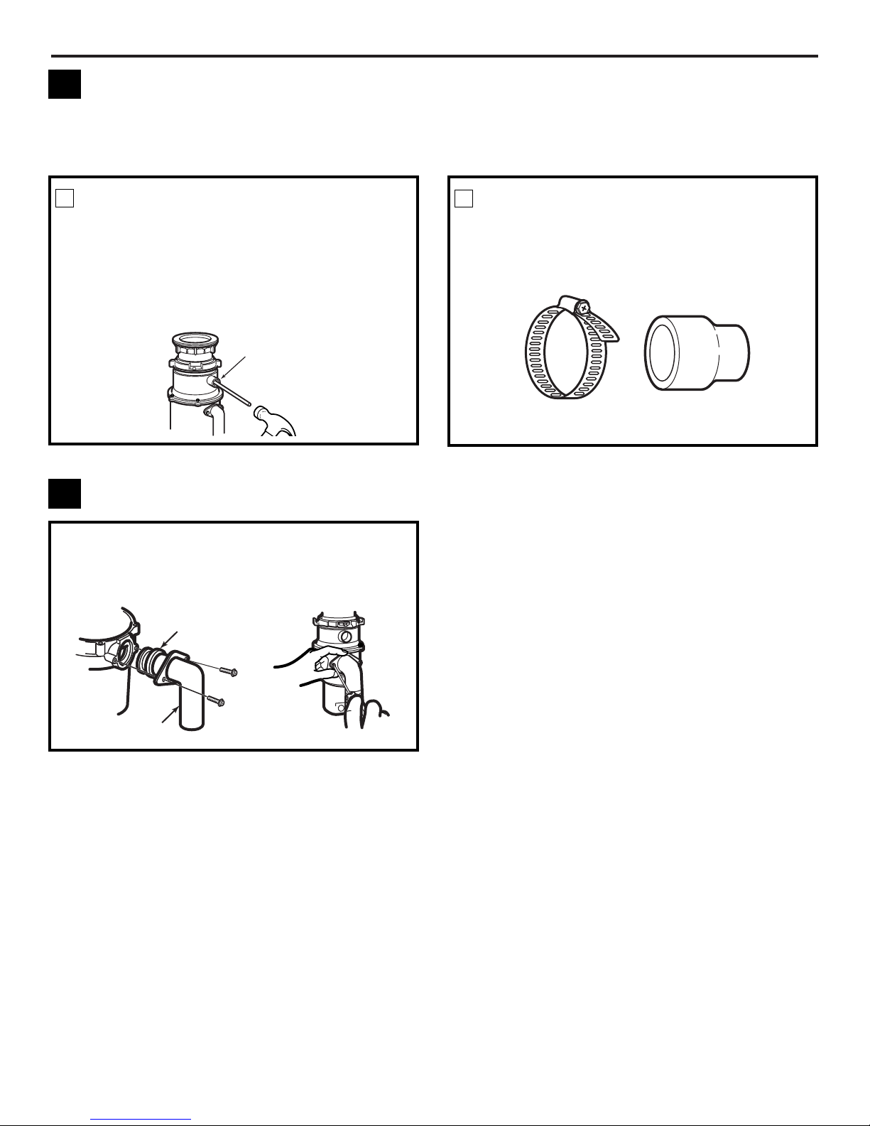
KNOCK OUT PLUG
Using a blunt instrument (steel punch or wooden
dowel), knock out entire plug. Do not use a
screwdriver or sharp instrument. When knockout
plug falls into disposer, you may remove it or
simply grind it up when the disposer is used. This
will not damage the disposer in any way, but may
take some time to grind, over the course of several
uses.
DISHWASHER CONNECTION (IF REQUIRED)
If you are connecting to a dishwasher, complete the
following step. If a dishwasher is not to be connected,
go on to “Attaching the Discharge Elbow” section.
1
Connect the dishwasher hose using a hose clamp.
If the hose size is different, you will need a
stepped rubber adapter.
CONNECT HOSE
2
2
Knock out
plug
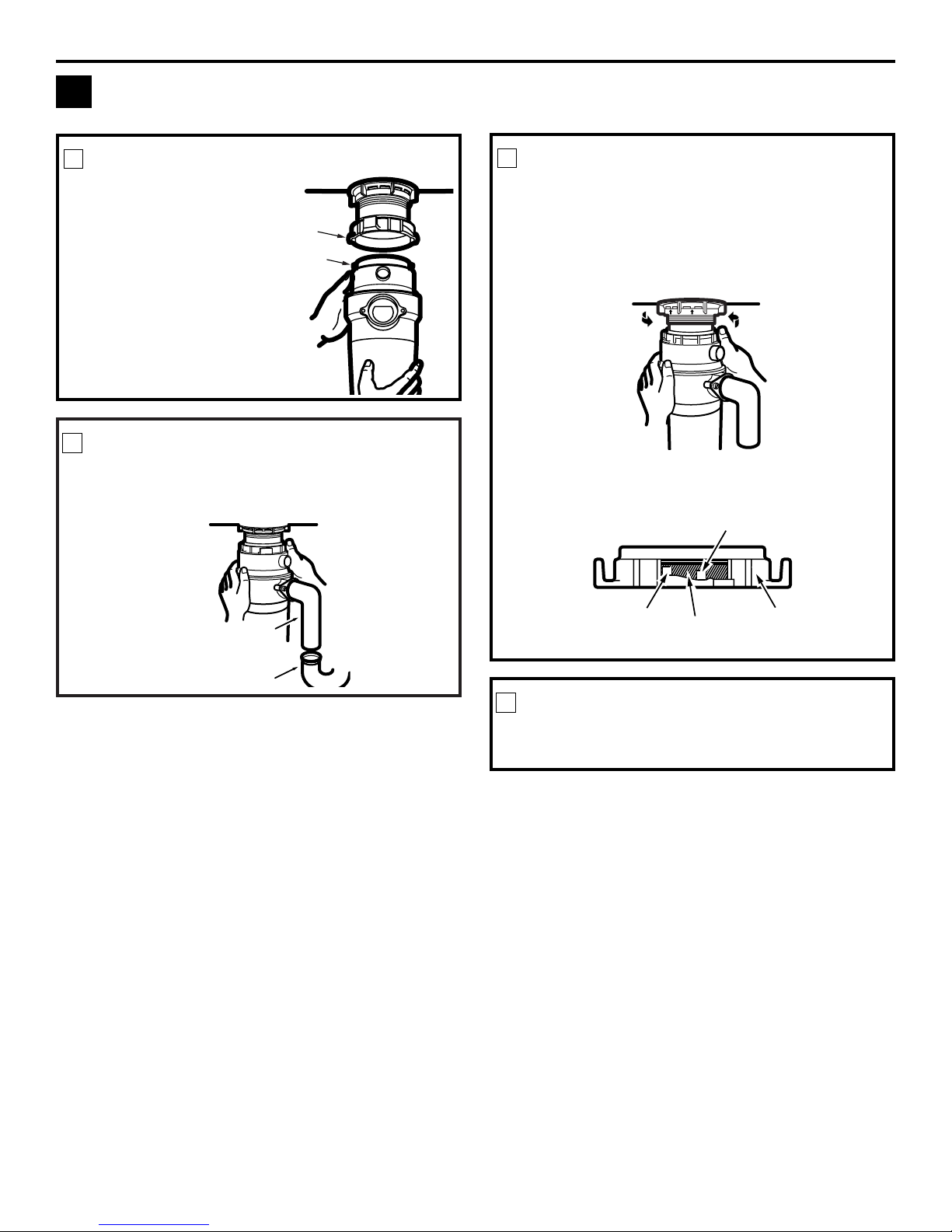
CONNECT DISCHARGE ELBOW
Connect the discharge elbow to the disposer.* Make
sure all plumbing connections are tight.
ATTACHING THE DISCHARGE ELBOW
3
Rubber
Gasket
Hose Clamp
Stepped Rubber Adapter
Discharge
Elbow
* Some installations (see page 8 for examples) may
require the use of a flexible drain pipe.
Page 7
7
LOCK MOUNT RING
Turn the mount ring slowly to the right until it
locks up tight. Hopper projections must be to the
extreme left of the mounting slots. If the mount
ring is hard to turn, you may add a small amount
of petroleum jelly or liquid soap to the hopper
projection. Run water and check for leaks.
3
Installation Instructions
Hopper Projection in
“Supported” Position
Hopper Projection
in “Locked” Position
Mount
Ring
Locking Detail
Check the unit for leaks 24 hours after installation
and first operation.
CHECK FOR LEAKS
4
CONNECTING DISPOSER TO SINK FLANGE
4
Line up the disposer
under the sink flange.
Guide the hopper
projections into the
mount ring slots. Turn
the mount ring about
1/4″ to the right so
that the disposer is
temporarily supported.
1
Turn the mount ring and the disposer until the
disposer discharge elbow lines up with the outlet
pipe (see page 8).
LINE UP WITH OUTLET PIPE
2
Mount
Ring Slot
Hopper
Projection
Discharge
Elbow
Outlet Pipe
ATTACH TO SINK FLANGE
Mounting Slot
Page 8
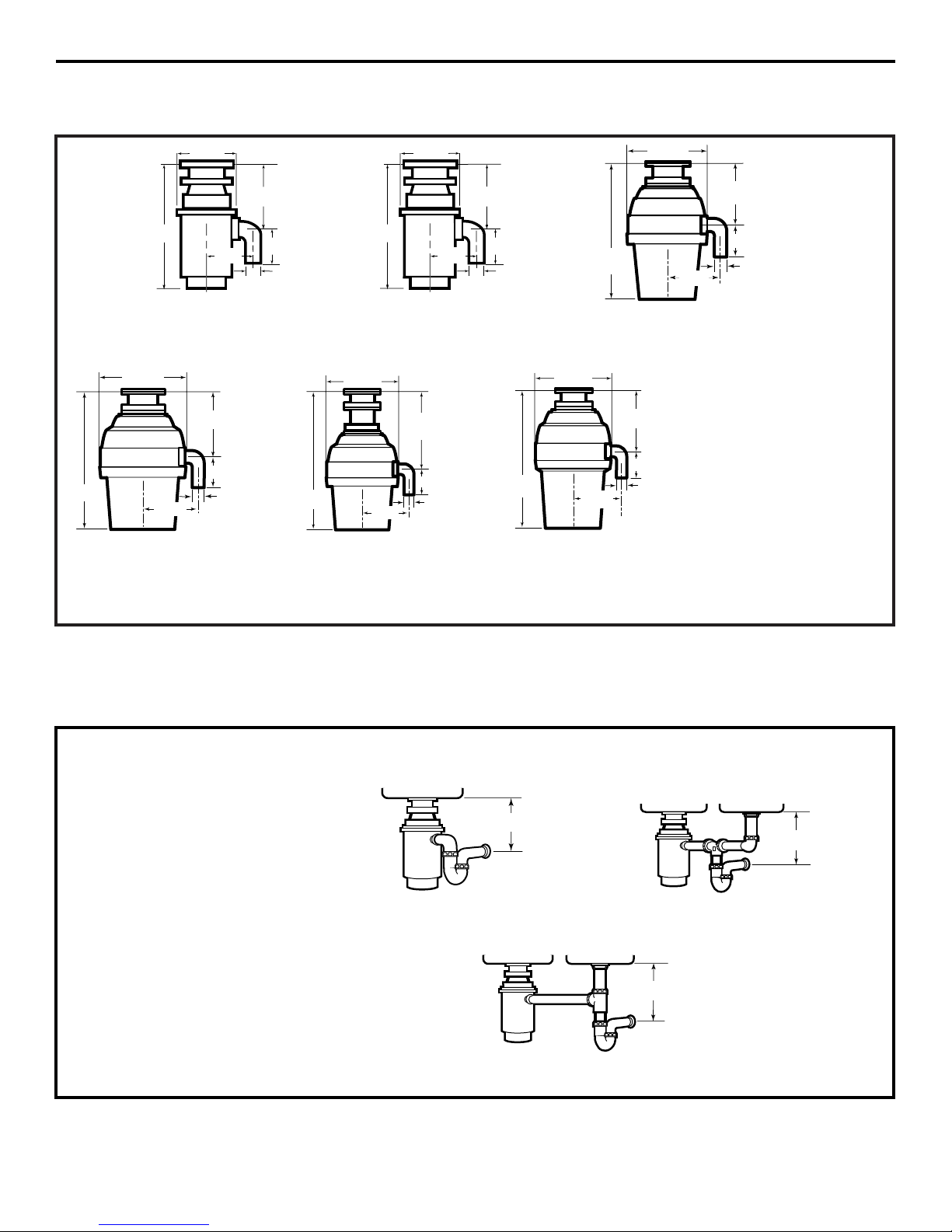
8
SINGLE BOWL
DOUBLE BOWL
CENTER OUTLET**
DOUBLE BOWL
END OUTLET**
*Approx.
*Approx.
*Approx.
GFC320 Model Series
DIMENSIONS
63/16”
5
3
/16”
12
11
/16”
41/2”
1
1
/2”
5
3
/8”
Direct replacement for most
makes & models.
*9″ for Model Series GFC320
and GFC520
*10″ for Model Series GFC530,
GFC720 and GFC1020
*12″ for Model Series GFB760
GFC520 Model Series
GFC530 Model Series
GFC720 Model Series GFC1020 Model Series
1
1
/2
”
1
1
/2”
1
1
/2”
5
9
/16”
7
1
/4”
8
1
/2”
16
1
/16”
7
1
/4”
8
1
/2”
5
9
/16”
141/2”
6
15
/16”
53/8”
7
3
/4”
13
7
/
16”
4
1
/2”
4
1
/2”
4
1
/2”
GFB760 Model Series
Batch Feed Operation
1
1
/2”
9
3
/8”
8
1
/2”
5
9
/16”
16
5
/8”
4
1
/2”
Installation Instructions
SOME TYPICAL INSTALLATIONS
63/16”
5
3
/16”
12
11
/16”
41/2
”
1
1
/
2”
5
3
/8”
**Flexible drain pipe may be necessary for this application.
NOTE: It is essential for the proper
operation of the disposer that this
dimension be 9″–12″, depending upon the
models listed above, to avoid standing water
in disposer motor housing.
Page 9

9
Operating instructions. ge.com
Continuous Feed Models
A. Remove the sink stopper and turn on
a medium flow of cold water.
B. Turn the switch to ON.
C. Scrape in food waste. To speed up food
waste disposal, cut or break up large
bones, rinds and cobs. Large bones
and fibrous husks require considerable
grinding time and are more easily
thrown away with other trash. Do not
be alarmed that the disposer slows down
while grinding. The disposer is actually
increasing torque (grinding power) and
is operating under normal conditions.
D. Before turning the disposer off, let
the water and the disposer run for
approximately 25 seconds after
shredding stops. This assures that
all waste is thoroughly flushed through
the trap and drain.
E. Do not use hot water while running the
disposer. Cold water will keep food waste
and fats solid so they can be flushed
down the drain.
This disposer uses anti-jam swivel impellers that make a clicking sound as they swing into place.
This indicates normal operation.
Batch Feed Models
A. Remove the sink stopper and turn on
a medium flow of cold water.
B. Scrape in food waste.
C. Insert the stopper to start the disposer.
One of the two small slots in the stopper
base must line up with the switch plunger
inside the neck of the disposer.
NOTE: The oval shaped handle aligns with the
2 small slots in the stopper.
Push down firmly to start.
D. Run the disposer for 25 seconds after
shredding stops. This assures that all
waste is thoroughly flushed through
the trap and drain.
Lift the stopper to shut the disposer off.
E. To fill the sink, insert the stopper so that
the largest slot lines up with the switch
plunger. The stopper can now be pushed
down to seal the sink without starting the
disposer. When the medium-sized slot in
the stopper base is lined up with the
switch plunger, water can drain, but
tableware, etc., cannot be accidentally
dropped into the disposer.
Oval
Handle
Small
Large
Small
Medium
Page 10

10
Helpful Hints
A. Be sure the disposer is empty before using
the dishwasher so it can drain properly.
B. You may want to leave the stopper in the
drain when not in use to prevent utensils
and foreign objects from falling into the
disposer.
C. The disposer is ruggedly built to give you
years and years of trouble-free service.
It will handle all normal food wastes--BUT it will not grind and dispose such
items as tin cans, bottles and bottle caps,
glass, china, leather, cloth, crockery,
rubber, string, feathers, or clam or oyster
shells. These are waste materials and
belong in the trash can or trash
compactor.
D. TO SPEED UP FOOD WASTE
DISPOSAL…Cut or break up large bones,
melon rinds, grapefruit skins and corn
cobs. Items such as large bones, fibrous
husks like lima bean pods and corn husks
require considerable cutting time. For this
reason, you may prefer to place them in
the trash can or trash compactor.
Operating instructions.
Care and maintenance.
THE MOTOR IS PERMANENTLY LUBRICATED FOR LIFE. DO NOT ATTEMPT TO LUBRICATE
YOUR DISPOSER. The disposer is self cleaning and scours itself with each use.
■
■ NEVER put lye or chemical cleaners into the
disposer, as they cause serious corrosion of
metal parts.
■
■ Your disposer, except for the Batch Feed
model, is equipped with a removable splash
guard for ease of cleaning or replacement.
Remove the splash guard by pulling it out
from the top. To replace, insert into the
sink flange and push down until it is
properly seated.
■
■ If an odor develops, run orange or lemon
rinds through the disposer. A dozen ice
cubes sprinkled with a little household
scouring powder will also work.
Page 11

Problem Possible Causes What To Do
Loud noises (other than Silverware, bottle cap or other • Remove the splash guard* and remove the object with
those during grinding of foreign object has fallen into long-handled tongs. Replace the splash guard.*
bones and fruit pits) the disposer.
Disposer does not start Reset button has been tripped. • With the splash guard* removed, check to see if the
turntable will move freely using a broom handle. If the
turntable moves freely, replace the splash guard* and check
the reset button to see if it has been tripped. The reset
button is red and located opposite the discharge elbow,
near the bottom of the disposer. Push the button in until
it clicks and remains depressed. If the reset button has not
been tripped, check for a shorted or broken wire connecting
to the disposer. Check the electrical power switch, fuse box
or circuit breaker. If wiring and electrical components are
intact, the unit may have internal problems that require
service or replacement.
Turntable cannot rotate. • If the turntable does not turn freely, check for an object
lodged between the turntable and the grind ring. Dislodge
the object by moving the turntable with a broom handle.
Then remove the object.
If no foreign object is present, there may be internal
problems.
Disposer leaks If the leak is at the top, it may be
caused by:
1. Improper seating of sink flange
(gasket choice, putty or tightening).
2. Support ring not tightened properly.
3. Defective cushion mount.
If the leak is at the discharge elbow,
leak may be caused by improper
tightening of elbow flange screws.
11
Before you call for service… ge.com
Troubleshooting Tips
Save time and money! Review the chart on this page first
and you may not need to call for service.
Reset
Button
Serial No.
Remove
Splash Guard
Turntable
WARNING!
Before resetting, disconnect the power supply–please see SAFETY NOTE above. The overload control prevents the motor
from operating should overloading occur. This feature protects your house wiring and your disposer. When overloaded,
the motor will stop automatically.
SAFETY NOTE: Before investigating, you must disconnect the power supply.
*Batch Feed does not include splash guard.
Page 12

Disposer Warranty.
All warranty service provided by our Factory Service Centers,
or an authorized Customer Care
®
technician. To schedule service,
on-line, 24 hours a day, visit us at ge.com, or call 800.GE.CARES
(800.432.2737). Please have serial and model numbers available
when calling for service
.
For The Period Of: GE Will Replace:
One Year The entire disposer if there is a defect in materials or workmanship relating to functional parts
From the date of the only (appearance parts are excluded). During this limited one-year warranty, GE will also provide,
original purchase free of charge, all labor charges related to replacing the original disposer along with the
replacement disposer within the first year.
■ Service trips to your home to teach you how to use
the product.
■ Improper installation, delivery or maintenance.
■ Failure of the product if it is abused, misused, or
used for other than the intended purpose or used
commercially.
■ Replacement of house fuses or resetting of circuit breakers.
■ Damage to the product caused by accident, fire, floods
or acts of God.
■ Incidental or consequential damage caused by possible
defects with this appliance.
■ Damage caused after delivery.
■ Product not accessible to provide required service.
What GE Will Not Cover:
This warranty is extended to the original purchaser and any succeeding owner for products purchased for home use
within the USA. If the product is located in an area where service by a GE Authorized Servicer is not available, you may
be responsible for a trip charge or you may be required to bring the product to an Authorized GE Service Location for
service. In Alaska, the warranty excludes the service calls to your home.
Some states do not allow the exclusion or limitation of incidental or consequential damages. This warranty gives you
specific legal rights, and you may also have other rights which vary from state to state. To know what your legal rights
are, consult your local or state consumer affairs office or your state’s Attorney General.
Warrantor: General Electric Company. Louisville, KY 40225
Staple your receipt here.
Proof of the original purchase
date is needed to obtain service
under the warranty.
12
EXCLUSION OF IMPLIED WARRANTIES—Your sole and exclusive remedy is product repair as provided in this
Limited Warranty. Any implied warranties, including the implied warranties of merchantability or fitness for a
particular purpose, are limited to one year or the shortest period allowed by law.
Page 13

Tri turador
de desechos de alimentos
ge.com
Manual del propietario
e instrucciones para
la instalación
165D4700P328 49-55008 12-05 JR
Información de seguridad
Cómo conectar
la corriente eléctrica . . . . . . . . . 2, 3
Precauciones de seguridad . . . . . 2
Instrucciones para
la instalación
Cómo conectar el codo
de descarga . . . . . . . . . . . . . . . . . . . 6
Cómo conectar el triturador
a la brida del lavaplatos . . . . . . . . .7
Componentes e instalación
para la brida del lavaplatos . . . . .5
Conexión hacia la lavadora
de platos . . . . . . . . . . . . . . . . . . . . . . 6
Dimensiones/
Instalaciones típicas . . . . . . . . . . . .8
Instrucciones de operación
Cuidado y mantenimiento . . . . .10
Modelos de alimentación
continua . . . . . . . . . . . . . . . . . . . . . . .9
Modelos de alimentación
por lote . . . . . . . . . . . . . . . . . . . . . . . .9
Consejos para la solución
de averías
Antes de llamar
para servicio . . . . . . . . . . . . . . . . . .11
Servicio al consumidor
Garantía . . . . . . . . . . . . . . . . . . . . 12
Escriba los números del modelo y
serie para su triturador aquí:
Modelo # __________________
Serie # ____________________
Los puede encontrar en una etiqueta
en la parte inferior del triturador.
Línea de Modelos Serie
GFC320
GFC520
GFC530
GFC720
GFC1020
GFB760
Page 14

¡ADVERTENCIA!
Al usar aparatos eléctricos, se deberán seguir precauciones básicas de seguridad, incluyendo las siguientes:
PRECAUCIONES DE SEGURIDAD
■
■ Use este aparato sólo para el propósito establecido
como se describe en este Manual del propietario.
■
■ Lea todas las instrucciones antes de utilizar
el aparato.
■
■ Para reducir el riesgo de lesiones, se requiere
de supervisión cercana cuando se use el aparato
cerca de los niños.
■
■ No ponga los dedos o las manos en el triturador
de comidas.
■
■ Gire el interruptor (normalmente un interruptor de
pared) a la posición de apagado antes de intentar
retirar una obstrucción o remover un objeto del
triturador.
■
■ Cuando intente retirar una obstrucción en el
triturador de alimentos, utilice un objeto de madera
largo como una cuchara de madera o el palo de
una escoba o trapero.
■
■ Cuando intente remover objetos de un triturador
de alimentos, utilice solamente herramientas o
utensilios no magnéticos de manija larga, ya que el
triturador podría ser accionado magnéticamente.
■
■ Para reducir el riesgo de lesiones por parte de
materiales que pudieran ser expulsados por el
triturador de desechos, no coloque lo siguiente en
el triturador:
a) Conchas de mariscos.
b) Limpiadores de drenaje cáusticos o productos
similares.
c) Vidrio, porcelana o plástico.
d) Huesos grandes.
e) Metal, como tapas de botella, latas, utensilios
o papel de aluminio.
f) Aceite caliente, u otros líquidos calientes.
g) Tusas de maíz enteras.
■
■ Cuando no esté operando el triturador, deje la tapa
de drenaje en su lugar para reducir el riesgo de que
caigan objetos dentro del triturador.
■
■ Consulte la porción de CONEXIÓN ELÉCTRICA de
este manual para las instrucciones apropiadas de
conexión a tierra.
2
IMPORTANTE INSTRUCCIONES DE SEGURIDAD.
LEA TODAS LAS INSTRUCCIONES ANTES DEL USO.
¡ADVERTENCIA!
CÓMO CONECTAR LA CORRIENTE ELÉCTRICA
Si no está familiarizado con la parte eléctrica y sus procedimientos, llame a un electricista calificado.
PELIGRO:La conexión incorrecta del sistema de polo
a tierra puede resultar en el riesgo de una descarga eléctrica.
Consulte con un electricista calificado o con un proveedor de
servicios si tiene dudas de que el aparato esté correctamente
conectado a tierra. No modifique el enchufe suministrado con
el aparato si no encaja en el tomacorriente; haga que un
electricista calificado instale un tomacorriente apropiado.
Para modelos equipados con un cable a tierra:
INSTRUCCIONES DE CONEXIÓN A TIERRA: Este aparato
debe ser conectado a tierra. En el caso de una avería o
daño, la conexión a tierra suministra una vía de menor
resistencia para la corriente eléctrica a fin de reducir el
riesgo de una descarga eléctrica. Este aparato está
provisto de un cable que tiene un conductor y un
enchufe de conexión a tierra. El enchufe debe
conectarse a un tomacorriente apropiado que esté
instalado correctamente y con conexión a tierra de
acuerdo con todos los códigos y regulaciones locales.
La mayoría de las casas tienen tomacorrientes eléctricos
debajo del lavaplatos que medio-calientes. Esto significa
que un tomacorriente está controlado por el
interruptor de la pared, mientras que el otro siempre
tiene corriente (caliente). El modelo “batch-feed” o
“TC” se conecta al lado que tiene corriente, mientras
que el modelo de suministro continuo se conecta al
lado del interruptor.
INSTRUCCIONES RELACIONADAS CON EL RIESGO DE INCENDIOS,
DESCARGAS ELÉCTRICAS O LESIONES A PERSONAS
Page 15

El cable eléctrico y/o las conexiones deben cumplir
con el código National Electric, Sección 422 y/o códigos
locales y ordenanzas.
Para modelos no equipados con un cable:
Si su triturador no viene equipado con un cable, usted
puede conectarlo de dos maneras:
1. Adhiera un cable eléctrico, de una longitud mínima
de 18″ y que no exceda 36.″ El Kit GE #PM3X115
proporciona las partes necesarias para hacer
esta conexión.
2. Conecte el triturador directamente al sistema eléctrico
de la casa. GE recomienda que la conexión la haga un
técnico calificado.
Para conectar un cable eléctrico:
INSTRUCCIONES DE CONEXIÓN A TIERRA: Este aparato debe
ser conectado a tierra. En el caso de una avería o daño, la
conexión a tierra suministra una vía de menor resistencia
para la corriente eléctrica a fin de reducir el riesgo de una
descarga eléctrica. El cable eléctrico (a instalar) debe tener
un conductor y un enchufe de conexión a tierra. El enchufe
debe conectarse a un tomacorriente apropiado que esté
instalado correctamente y con conexión a tierra de acuerdo
con todos los códigos y regulaciones locales. Si no existen
códigos locales y/u ordenanzas, el enchufe debe ajustarse
a los requisitos NEC.
PELIGRO: La conexión incorrecta del sistema de polo a
tierra puede resultar en el riesgo de descarga eléctrica. Consulte con
un electricista calificado o con un proveedor de servicios si tiene dudas
de que el aparato esté correctamente conectado a tierra.
NOTA: Desconecte la energía eléctrica hacia el circuito del triturador
antes de la instalación. Fije el interruptor del circuito en la posición de
apagado (OFF) o retire el fusible.
A. Conecte el triturador únicamente a una corriente
de 110-120 voltios, 60 Hz de corriente alterna (AC).
B. Si se utiliza un enchufe con cable, use un enchufe de
tres patas. Se debe agregar una línea de tierra al tornillo
de conexión a tierra en la parte inferior del triturador
(campana extremo).
C. Utilice un conectador de alivio de
presión de la abrazadera del cable
donde el cable de corriente entra
al triturador.
Para conectar el triturador directamente
a la corriente de la casa:
GE recomienda que la conexión la haga un técnico calificado.
INSTRUCCIONES DE CONEXIÓN A TIERRA: Este aparato
se debe conectar a un sistema de cableado permanente,
metálico conectado a tierra, o se debe correr un conductor
de conexión a tierra para equipos con los conductores del
circuito y conectarse al terminal de conexión a tierra para
equipos o al conductor en el aparato.
PELIGRO: La conexión incorrecta del sistema de polo a
tierra puede resultar en el riesgo de descarga eléctrica. Consulte con un
electricista calificado o con un proveedor de servicios si tiene dudas
de que el aparato esté correctamente conectado a tierra.
A. Si utiliza un cable BX:
1. Instale el conectador de cable en el orificio.
2. Conecte el cable blanco al conductor blanco
del triturador.
3. Conecte el cable negro.
4. Conecte el alambre pelado de tierra.
Si no se utiliza un cable BX, instale un cable por separado
de conexión a tierra a una conexión a tierra más cercana,
utilizando el tornillo en la campana extremo para el cable
de conexión a tierra.
B. Si su suministro de corriente no incluye un cable de
conexión a tierra, debe adquirir uno a menos que se
utilice un cable metálico. Conecte firmemente un cable
de cobre al tornillo de polo a tierra del triturador y
conecte el otro extremo del cable a una conexión a tierra
más cercana. Use solamente abrazaderas de conexión a
tierra aprobadas por UL. Si en su casa se utilizan tuberías
de plástico, un electricista calificado debe instalar una
conexión a tierra adecuada. La mayoría de las casas
tienen tomacorrientes eléctricos debajo del lavaplatos
que medio-calientes. Esto significa que un tomacorriente
está controlado por el interruptor de la pared, mientras
que el otro siempre tiene corriente (caliente). El modelo
“batch-feed” o “TC” se conecta al lado que tiene corriente,
mientras que el modelo de suministro continuo se conecta
al lado del interruptor.
LEA Y SIGA CUIDADOSAMENTE ESTA INFORMACIÓN DE SEGURIDAD.
CONSERVE ESTAS INSTRUCCIONES
3
ge.com
Busque el conductor conectado a
esta hoja y una ese conductor al
cable blanco del triturador.
Lado con
costura
NOTA: Al ver el costado del
enchufe eléctrico con el
dispositivo de conexión a tierra
en la parte superior, la hoja
izquierda más larga se conecta
con el cable identificado.
Liberación
de presión
Tuerca
Botón rojo para
reposición
Tornillo de conexión
a tierra
Tuercas del cable
Retire la tapa
Hacia la corriente
de la casa o cable
de corriente
¡ADVERTENCIA!
CÓMO CONECTAR LA CORRIENTE ELÉCTRICA (Continuación)
Si no está familiarizado con la parte eléctrica y sus procedimientos, llame a un electricista calificado.
Fondo del triturador (campana extremo)
Page 16

• Destornillador de estrella
y con hoja plana
• Alicates de cierre de canal,
de juntas deslizantes
• Martillo
• Llave
4
ANTES DE EMPEZAR
Lea estas instrucciones completa y cuidadosamente.
•
IMPORTANTE – Guarde estas
instrucciones para uso del inspector local.
•
IMPORTANTE – Observe todos los
códigos y órdenes de ley.
• Nota al instalador – Asegúrese de dejar estas
instrucciones con el consumidor.
• Nota al consumidor – Conserve estas
instrucciones para referencia futura.
• Nivel de destreza – La instalación de este aparato
requiere de destrezas mecánicas básicas.
• Tiempo de ejecución – 1 hora
• La instalación apropiada es la responsabilidad
del instalador.
• La falla del producto debido a una instalación
inadecuada no está cubierta por la garantía.
Si tiene preguntas, llame al 800.GE.CARES (800.432.2737) o Visite nuestra página en la red: ge.com
Instrucciones
Triturador
para la instalación
QUÉ NECESITA
MATERIALES ADICIONALES QUE USTED
PODRÍA NECESITAR
• Punzón de acero o clavija de madera
• Petrolato o jabón líquido
• Abrazadera de manguera
• Conectador de drenaje para lavadora de platos
• Llave de tubos ajustable
• Masilla de plomero (para sellado del lavaplatos)
• Adaptador de drenaje de caucho escalonado
• Tuercas de alambre
• Cable conectador
• Tubería de drenaje flexible
• Kit del cable eléctrico (Parte No. PM3X215GDS)
PREPARACIÓN
1. Desconecte el suministro del cable eléctrico hacia
el triturador.
2. Remueva el triturador viejo o la ensambladura
de la brida del lavaplatos.
3.
Inspeccione la línea de drenaje. Si la línea de drenaje
se encuentra muy cubierta con grasa endurecida y
acumulaciones, serpentee con una serpiente de
plomero.
4. Remueva los materiales de sellado viejos y los pedazos
de juntas de la abertura del lavaplatos, tanto arriba
como abajo.
NOTA: Las superficies superiores e inferiores del
lavaplatos deben estar libres de materiales para prevenir
fugas.
Page 17

NOTA: Ponga mucha atención al orden de las piezas de la
ensambladura de la brida del lavaplatos, ya que han sido ensambladas
correctamente por el fabricante.
A. Desensamble la ensambladura de la brida del lavaplatos del
triturador girando el aro de montaje hacia la izquierda (en sentido
de las agujas del reloj) y remuévalo.
B. Levante el aro de montaje hacia la parte superior de la
ensambladura de la brida del lavaplatos. Remueva el montaje de
amortiguado y el aro de montaje. Quizás usted quiera practicar
instalando el montaje de amortiguado en ese momento antes de
trabajar debajo del lavaplatos.
C. Destornille el aro de soporte de la brida del lavaplatos y retire
el empaque de fibra. Ahora le resta la brida del lavaplatos y el
empaque de caucho.
D. El empaque de caucho sirve en vez de la masilla de plomero en
lavaplatos de acero inoxidable.
E. Si no se utiliza masilla, introduzca la brida del lavaplatos a través del
empaque de caucho en la abertura del lavaplatos. No rote la brida
una vez esté colocada.
F. Si utiliza masilla en vez del empaque, forme un aro alrededor
del costado inferior de la brida del lavaplatos. Inserte la brida
en la abertura del lavaplatos, presione hacia abajo con fuerza hasta
retirar completamente el exceso de masilla. Desde abajo del
lavaplatos, quite el exceso de masilla con el borde inferior de
la abertura del lavaplatos. Use la masilla en pequeñas cantidades
en lavaplatos de hierro fundido.
G. Desde abajo del lavaplatos, deslice el
empaque de fibra hacia la brida del
lavaplatos expuesta. Con las flechas hacia
arriba, atornille el aro de soporte en la
brida del lavaplatos, apriete con la mano
hasta que la brida del lavaplatos no se
mueva. En este momento, quizás quiera
insertar un tapón en el lavaplatos y llenarlo
con agua para revisar el sello de la brida del
lavaplatos y asegurarse de que no haya fugas.
H. Coloque el aro de montaje sobre la brida
del lavaplatos y sosténgalo en su lugar
mientras instala el montaje de amortiguado
(el lado grande hacia abajo). Cerciórese de
que la ranura en el interior del montaje de
amortiguado ajuste sobre el labio de la brida
del lavaplatos, similar a cuando usted coloca
una tapa en la boca
plástica de un envase.
Pase sus dedos alrededor
de todo el montaje de
amortiguado haciendo
un poco de presión. No presione demasiado. Cuando el montaje
de amortiguado haya asentado apropiadamente, el aro de montaje
puede ser empujado hacia abajo sobre el montaje de amortiguado
y entonces estará libre para girar.
5
Instrucciones para la instalación
COMPONENTES E INSTALACIÓN
1
COMPONENTES
INSTALACIÓN PARA LA BRIDA DEL LAVAPLATOS
(Lea completamente antes de empezar.)
Ranura
Arriba
Reborde
inferior
Empaque de caucho
escalonado
Lavaplatos
Empaque
de fibra
Reborde del montaje
de cojín inferior
Aro de soporte
Área abierta sin
obstrucción
Brida del
lavaplatos
El aro del montaje deberá estar libre
para moverse hacia arriba y abajo
Detalles del montaje de cojín
*Tapón
*Protector removible
contra salpicaduras
Brida del lavaplatos
Empaque de caucho de la
brida del lavaplatos
Ranura
Entrada de descarga de
la máquina lavaplatos
Empaque del codo
Tol va
Lavaplatos
Empaque de fibra
Observe las flechas
que señalan hacia
arriba
Tornillos
Codo de
descarga
Brida del
codo
Aro de montaje
Etiqueta de calificación
en esta área
Orejas para
apretar
Campana
final
(Conexiones
eléctricas)
Montaje de cojín
*No use con modelo de alimentación por lote
Brida del
lavaplatos
Ensambladura
de la brida
del lavaplatos
Triturador
Apriete con la
mano la brida del
lavaplatos
Ensambladura de la brida del lavaplatos correctamente instalada
Ranura
Montaje de
amortiguado
Reborde inferior
(se muestra para que la orientación sea apropiada)
Page 18

6
Instrucciones para la instalación
TAPÓN DE VACIADO
Con un instrumento sin punta (punzón de acero o
clavija de madera), retire el tapón completamente.
No use un destornillador o instrumento afilado.
Cuando el tapón de vaciado caiga dentro del
triturador, lo puede quitar o simplemente tritúrelo
cuando utilice el triturador. Esto no dañará de
ninguna manera el triturador, pero puede tomar
algún tiempo para triturarse, en el transcurso
de varios usos.
CONEXIÓN HACIA LA LAVADORA DE PLATOS (SI SE REQUIERE)
Si usted está conectando una lavadora de platos,
complete el siguiente paso. Si por el contrario, usted
no va a conectar una lavadora de platos, pase a la
sección “Sujetando el codo de descarga.”
1
Conecte la manguera de la lavadora de platos
utilizando una abrazadera de manguera. Si el
tamaño de la manguera es diferente, necesitará
un adaptador de caucho escalonado.
CONECTE LA MANGUERA
2
2
Tapón de
vaciado
CONECTE EL CODO DE DESCARGA
Conecte el codo de descarga al triturador.*
Asegúrese de que todas las conexiones de la tubería
estén apretadas.
CÓMO CONECTAR EL CODO DE DESCARGA
3
Empaque
de caucho
Abrazadera de manguera
Adaptador de caucho escalonado
Codo de
descarga
* Algunas instalaciones (ver la página 8 para ejemplos)
puede que requieran el uso de una tubería de drenaje
flexible.
Page 19

7
CONECTE A LA BRIDA DEL LAVAPLATOS
Alinee el triturador
debajo la brida del
lavaplatos. Guíe las
proyecciones de la
tolva hacia las
ranuras en el aro
de montaje. Dele
vuelta al aro de
montaje unos 1/4″
hacia la derecha,
de manera que el
triturador quede
temporalmente
apoyado.
COMO CONECTAR EL TRITURADOR A LA BRIDA DEL LAVAPLATOS
1
Gire el aro de montaje y el triturador hasta que
el codo de descarga del triturador se encuentre
alineado con el tubo de salida (ver página 8).
ALINEE CON EL TUBO DE SALIDA
2
4
Ranura del aro
de montaje
ASEGURE EL ARO DE MONTAJE
Gire el aro de montaje hacia la derecha
lentamente hasta que quede asegurado
firmemente. Las proyecciones de la tolva deben
estar hacia el extremo izquierdo de las ranuras
del montaje. Si el aro de montaje es difícil de
girar, le puede agregar una pequeña cantidad
de petrolato o de jabón líquido a la proyección
de la tolva. Haga correr agua y revise las fugas.
3
Instrucciones para la instalación
La proyección de la tolva
en posición “de soporte”
Proyección de
embudo
Codo de descarga
Tubería de salida
La proyección de la tolva
en posición “asegurada”
Aro de
montaje
Detalles del aseguramiento
Inspeccione la unidad en busca de fugas 24 horas
después de la instalación y de la primera operación.
REVISE LAS FUGAS
4
Ranura
del montaje
Page 20

8
TAZÓN SENCILLO
TAZÓN DOBLE
SALIDA CENTRAL**
TAZÓN DOBLE
SALIDA LATERAL**
*Aproximadamente
*Aproximadamente
*Aproximadamente
Modelo de serie GFC320
DIMENSIONES
63/16”
5
3
/16”
12
11
/16”
4
1
/2”
1
1
/2
”
5
3
/8”
Reposición directa para la mayoría de
las marcas y modelos.
*9″ para los modelos de serie
GFC320 y GFC520
*10″ para los modelos de serie
GFC530, GFC720 y GFC1020
*12″ para el modelo de serie GFB760
Modelo de serie GFC520
Modelo de serie GFC530
Modelo de serie GFC720 Modelo de serie GFC1020
1
1
/2
”
1
1
/
2”
1
1
/2”
5
9
/
16”
7
1
/4
”
8
1
/2”
16
1
/16
”
71/
4”
8
1
/2”
5
9
/
16”
14
1
/2”
6
15
/16”
5
3
/8”
7
3
/4”
13
7
/16”
4
1
/2”
4
1
/2”
4
1
/2”
Modelo de serie GFB760
Operación de alimentación por lote
1
1
/2”
9
3
/8”
8
1
/2”
5
9
/16”
16
5
/8”
4
1
/2”
Instrucciones para la instalación
ALGUNAS INSTALACIONES TÍPICAS
**Una tubería de drenaje flexible podría ser necesaria para esta aplicación.
63/16”
5
3
/16”
12
11
/16”
4
1
/2”
1
1
/2”
5
3
/8”
NOTA: Para lograr una operación del
triturador apropiada, es esencial que esta
dimensión sea 9″–12″, dependiendo de los
modelos enumerados anteriormente, para
evitar agua estancada en el alojamiento
del motor del triturador.
Page 21

A. Retire el tapón del lavaplatos y gire el grifo
a un flujo medio de agua fría.
B. Vierta los desechos de comida.
C. Inserte el tapón para iniciar el triturador.
Una de las dos ranuras pequeñas en la base
del tapón debe estar alineada con el émbolo
del interruptor dentro del cuello del
triturador.
NOTA: La manija en forma de óvalo se alinea con
las dos pequeñas ranuras del tapón.
Empuje firmemente para arrancar.
D. Corra el triturador por 25 segundos después
de que la trituración termine. Esto asegura
que todo los desechos se evacuen
completamente a través del desagüe.
Levante el tapón para apagar el triturador.
E. Para llenar el lavaplatos, inserte el tapón de
forma que la ranura más grande se alinee
con el émbolo del interruptor. El tapón
puede ahora ser empujado hacia abajo para
sellar el lavaplatos sin iniciar el triturador.
Cuando la ranura de tamaño medio de la
base del tapón se alinea con el émbolo del
interruptor, se puede drenar el agua, pero
los cubiertos, etc., no pueden caer
accidentalmente al triturador.
9
Instrucciones de operación.
ge.com
Modelos de alimentación continua
A. Remueva el tapón del lavaplatos y conecte
a un flujo medio de agua fría.
B. Coloque el interruptor en ON (Encendido).
C. Vierta los desechos de comida. Para agilizar
la trituración de los desechos de comida,
corte o parta los huesos grandes, las cáscaras
y las tusas de maíz. Los huesos grandes y las
cáscaras fibrosas requieren de un triturado
de mayor tiempo y es más fácil desecharlos
con la otra basura. No se alarme si el
triturador disminuye su velocidad mientras
tritura. El triturador en realidad está
aumentando la fuerza de torque (potencia
de trituración) y está operando bajo
condiciones normales.
D. Antes de apagar el triturador, deje que el
agua y el triturador corran por 25 segundos
aproximadamente después de que la
trituración termine. Esto asegura que todos
los desperdicios fluyan completamente a
través del desagüe.
E. No use agua caliente mientras el triturador
está funcionando. El agua fría evitará que
los desperdicios de alimentos y las grasas
se solidifiquen, permitiendo así que sean
purgados más fácilmente.
Este triturador utiliza propulsores giratorios que impiden los atascamientos y producen un sonido ligero cuando se mueven
hacia su lugar. Esto indica una operación normal.
Modelos de alimentación por lote
Empuñadura
oval
Pequeño
Grande
Pequeño
Mediano
Page 22

10
■
■ NUNCA coloque lejía o limpiadores químicos
en el triturador, ya que éstos causan corrosión
seria a las partes metálicas.
■
■ Su triturador, excepto para el modelo de
alimentación por lote, está equipado con un
protector de salpicaduras removible para una
fácil limpieza o reposición. Retire el protector
de salpicaduras empujándolo hacia fuera
desde arriba. Para reemplazarlo, insértelo en
la brida del lavaplatos y empújelo hacia abajo
hasta que quede correctamente instalado.
■
■ Si llegara a sentir algún mal olor, purgue
cortezas de naranja o limón a través del
triturador. Una docena de cubitos de hielo
salpicados con un poco de polvo limpiador
casero también funciona.
Consejos útiles
A. Cerciórese de que el triturador esté vacío
antes de usar la lavadora de platos para
que pueda drenar apropiadamente.
B. Quizás desee dejar el tapón en el desagüe
cuando no esté en uso para impedir que
utensilios y objetos extraños caigan dentro
del triturador.
C. El triturador está firmemente fabricado para
brindarle años de servicio sin problemas.
Manejará todo tipo de desechos de comida
normales, pero no triturará elementos como
latas, botellas, tapas de botella, vidrio,
porcelana, cuero, telas, vasijas de barro,
caucho, cordones, plumas o conchas de
ostras o de mariscos. Estos son materiales
de desecho y deben ir en la basura o en el
compactador de basura.
D. PARA AGILIZAR LA TRITURACIÓN DE
DESECHOS DE ALIMENTOS… Corte o
parta los huesos grandes, la corteza del
melón, las cáscaras de la toronja y las tusas de
maíz. Elementos como huesos grandes y
cáscaras fibrosas como las vainas de las judías
y las tusas de mazorca requieren de más
tiempo para cortar. Por esta razón, quizás
quiera ponerlos en la basura o en el
compactador de basuras.
Instrucciones de operación.
Cuidado y mantenimiento.
EL MOTOR ESTÁ PERMANENTEMENTE LUBRICADO DE POR VIDA. NO INTENTE LUBRICAR
SU TRITURADOR. El triturador se limpia solo y se purga en cada uso.
Page 23

Problema Posibles causas Qué hacer
Ruidos fuertes (diferentes Platería, tapas de botellas y •Remueva el protector de salpicaduras* y remueva el objeto con
a aquellos durante la otros objetos extraños que un par de tenacillas o pinzas largas. Reemplace el protector de
trituración de huesos y hayan caído en el interior salpicaduras*.
pasteles de fruta) del triturador.
El triturador no arranca El botón de reposición se ha •Con el protector de salpicaduras* removido, inspeccione y
saltado. cerciórese de que el mecanismo gira libremente usando un
palo de escoba. Si gira libremente, reemplace el protector de
salpicaduras* e inspeccione el botón de reajuste para ver si se
disparó. El botón de reajuste es rojo y está localizado en el lado
opuesto del codo de descarga, cerca del fondo del triturador.
Empuje el botón hasta que haga clic y se quede hundido. Si el
botón de reajuste no se ha disparado, inspeccione en búsqueda
de algún corto circuito o algún alambre roto en la conexión del
triturador. Inspeccione el interruptor eléctrico, la caja de fusibles
o los interruptores. Si el cableado y los componentes eléctricos
están intactos, es posible que la unidad tenga problemas
internos que requieren ser reparados por un técnico o quizás
sea necesario cambiar la unidad.
La placa giratoria no puede rotar. •Si el mecanismo no gira libremente, inspeccione en búsqueda
de algún objeto atascado entre el mecanismo girador y el aro
de triturado. Desatasque el objeto moviendo el mecanismo con
un palo de escoba. Entonces remueva el objeto.
Si no hay ningún objeto extraño, puede que haya problemas
internos.
Escape del triturador Si el escape es en la parte superior, es posible
que se deba a:
1. Instalación incorrecta de la brida del lavaplatos
(tipo de empaque, masilla o apretado).
2. El aro de soporte no se apretó correctamente.
3. Montaje incorrecto del cojín.
Si el escape es en el codo de desechos, quizás se
deba a un apretado no apropiado de los tornillos
de la brida del codo.
11
Antes de llamar para solicitar servicio...
ge.com
Consejos para la solución de averías
¡Ahorre tiempo y dinero! Revise las tablas en las siguientes páginas
primero y quizás no necesite llamar a solicitar el servicio.
Botón de reajuste
No. de serie
Retire el protector
de salpicaduras
Placa giratoria
¡ADVERTENCIA!
Antes de presionar el botón de reposición, desconecte el suministro de corriente eléctrica, y por favor lea la
NOTA DE SEGURIDAD anterior. El control de sobrecarga evita que el motor opere si ocurriera una sobrecarga.
Esta característica protege las instalaciones eléctricas de su casa y su triturador. Cuando se sobrecargue,
el motor parará automáticamente.
NOTA DE SEGURIDAD: Antes de investigar, debe desconectar el suministro de energía.
* El modelo de alimentación por lote no incluye el protector de salpicaduras.
Page 24

Esta garantía se extiende al comprador original y cualquier comprador posterior de productos comprados para uso residencial
dentro de Estados Unidos. Si el producto está situado en un área que no dispone de servicio por parte de un proveedor de
servicio autorizado de GE, podría tener que hacerse cargo de los costes de envío o bien podría solicitársele que lleve el
producto a una centro de servicio de GE autorizado para realizar la reparación. En Alaska, la garantía excluye el costo de envío
o las visitas de servicio a su casa.
Algunos estados no permiten la exclusión o limitación de daños incidentales o consecuenciales. Esta garantía le proporciona
derechos legales específicos, y puede tener otros derechos que pueden variar de un estado a otro. Para conocer los derechos
legales de su estado, consulte con su oficina local de asuntos del consumidor o al procurador general de su estado.
Garantidor: General Electric Company. Louisville, KY 40225
■ Los viajes de servicio hacia su casa para enseñarle
cómo usar el producto.
■ Instalación o entrega inapropiada, o mantenimiento
impropio.
■ Remplazo de fusibles de su casa o reajuste del sistema
de interruptores de su casa.
■ Los fallos del producto si el mismo es abusado,
usado inapropiadamente, o usado para propósitos
no contemplados, o para usos comerciales.
■ Daños al producto causados por un accidente, incendio,
inundaciones o desastres naturales.
■ Daños incidentales o consecuenciales causados por posibles
defectos con este electrodoméstico.
■ Causar daños después de la entrega.
■ Producto no accesible para facilitar el servicio requerido.
Lo que GE no cubrirá:
Garantía del Triturador Doméstico de Desechos de Alimentos.
Todos los servicios de garantía son brindados por nuestros centros de
servicio de fábrica, o un técnico autorizado de Customer Care.
®
Para
programar el servicio en línea 24 horas al día, visítenos al ge.com, o llame
al 800.GE.CARES (800.432.2737). Cuando llame para solicitar servicio, por
favor tenga a mano el número de serie y el número de modelo.
Grape su recibo aquí. Usted
necesitará una prueba de la
fecha original de su
compra para obtener servicio
bajo la garantía.
Para el período de: GE reemplazará:
Un año El triturador doméstico de desechos de alimentos será reemplazado en su totalidad si existe algún
A partir de la fecha de defecto en los materiales o en la fabricación relacionado con las partes funcionales solamente
la compra original (excluyendo las partes de apariencia). Durante esta garantía limitada de un año, GE también
proporcionará, de manera gratuita, toda la mano de obra relacionada con el reemplazo del
triturador, además de un triturador de reemplazo durante este primer año.
12
EXCLUSIÓN DE GARANTÍAS IMPLÍCITAS—Su único y exclusivo derecho es la reparación del producto, tal y
como se indica en esta Garantía limitada. Cualquier garantía implícita, incluyendo las garantías implícitas de
comerciabilidad o adecuación para un fin determinado, están limitadas a un año o el período de tiempo más
breve permitido por la ley.
 Loading...