

Page 1
GE
Lighting
Evolve
Salem (EPST)
BEFORE YOU BEGIN
Read these instructions completely and carefully.
Save these instructions for future use.
Installation Guide
GEH-6005A
™
LED Post Top
WARNING
Risk of electrical shock. Disconnect power before servicing
or installing product.
WARNING
Risk of injury or damage. Unit will fall if not installed
properly. Follow installation instructions.
CAUTION
Risk of injury. Wear safety glasses and gloves during
installation and servicing.
This device complies with Part 15 of the FCC Rules. Operation is
subject to the following two conditions: (1) This device may not cause
harmful interference, and (2) this device must accept any interference
received, including interference that may cause undesired operation.
This Class [A] RFLD complies with the Canadian standard ICES-003.
Ce DEFR de la classe [ A ] est conforme à la NMB-003 du Canada.
Note: This equipment has been tested and found to comply with
the limits for a Class A digital device, pursuant to part 15 of the FCC
Rules. These limits are designed to provide reasonable protection
against harmful interference when the equipment is operated in
a commercial environment. This equipment generates, uses, and
can radiate radio frequency energy and, if not installed and used
in accordance with the instruction manual, may cause harmful
interference to radio communications. Operation of this equipment
in a residential area is likely to cause harmful interference in which
case the user will be required to correct the interference at his own
expense.
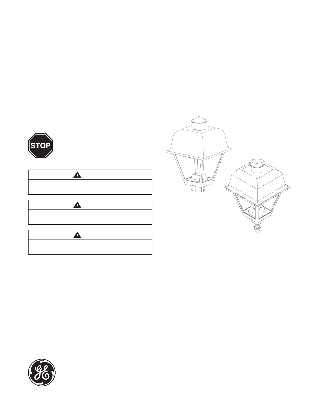
Standard Mounting
Pendant Mounting
• This luminaire is designed for outdoor lighting service,
and should not be used in areas of limited ventilation,
or in high ambient temperature enclosures.
• Best results will be obtained if installed and
maintained according to the following
recommendations.
imagination at work
Page 2
UNPACKING
1
3
WIRING
• This luminaire has been properly packed so that no
parts should have been damaged during transit.
• Inspect to conrm.
MOUNTING
2
WARNING
Risk of injury or damage. Unit will fall if not installed
properly. Follow installation instructions.
Standard Mounting
• This luminaire is provided with means for mounting on
3-inch (76mm) max. outside diameter pole tops.
• Feed the power supply leads through the sliptter wire
access hole as the xture is installed on the pole.
• Orient canopy screw or latch toward street and level
by adjusting the 3 screws, and tighten.
• Caution: Tighten screws to 15 - 20 ft-lbs (20-27 N-m).
• Remove shipping ties from wire way in the rear upright.
• NOTE: Make all electrical connections in accordance
with the National Electrical Code and any applicable
local code requirements.
• NOTE: Verify that supply voltage is correct by
comparing it to nameplate.
Standard Mounting
• Remove cover at base of unit and connect all 3 power
leads to the terminal block.
• Replace cover.
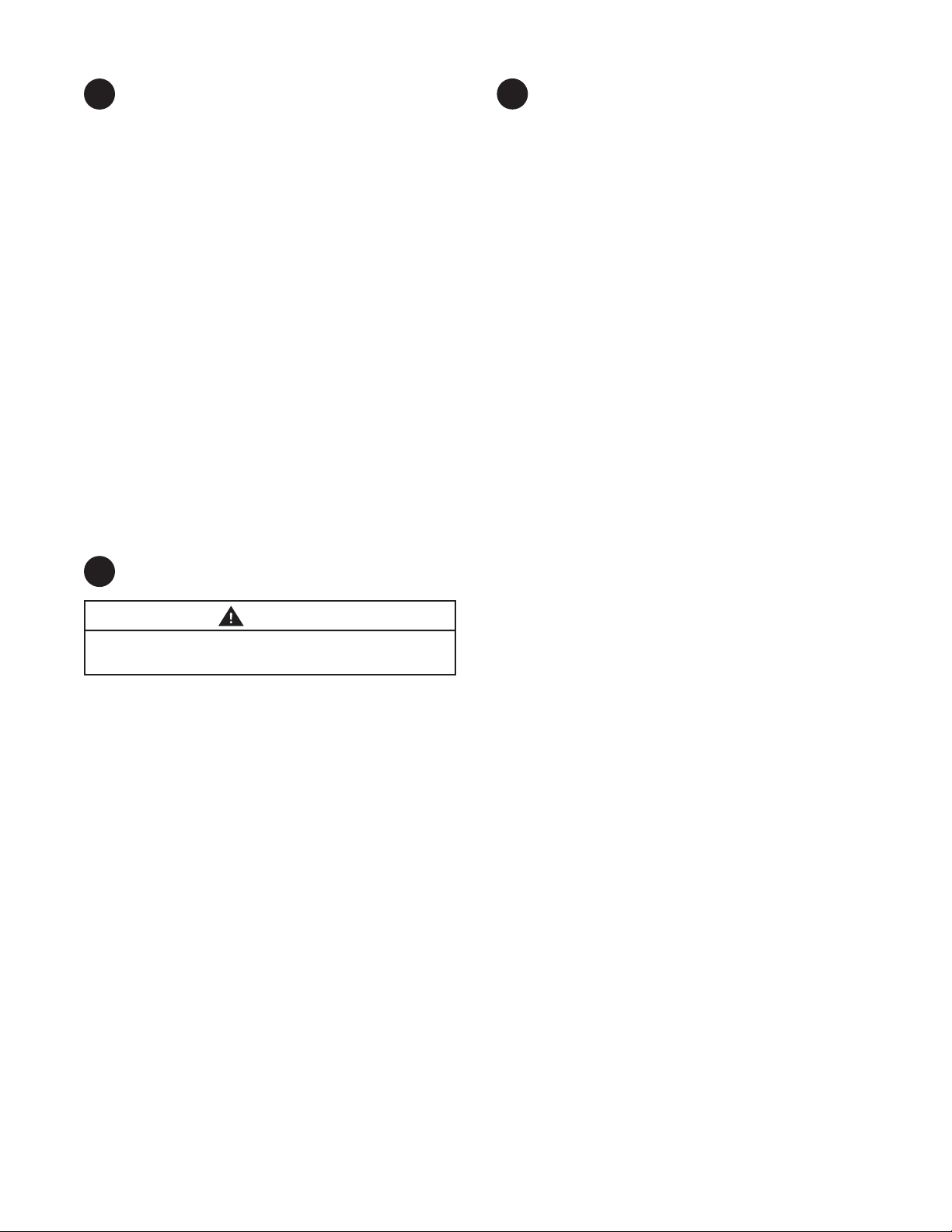
Pendant Mounting
• Remove one screw to open the top of the xture.
Allow the bottom to hang from it’s hinges.
• Pull the wires into the top housing.
• Connect all 3 power leads to the terminal block in the
top housing.
• Close top and replace the latch.
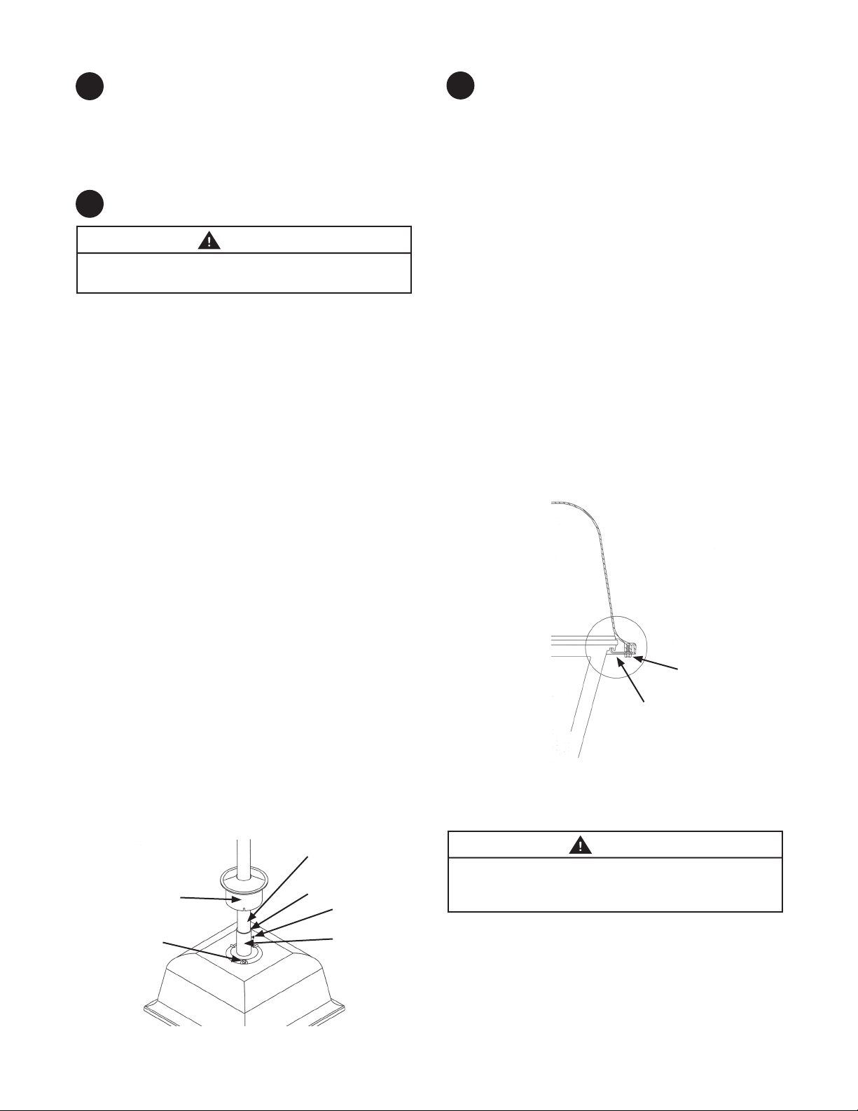
Pendant Mounting
• Use 1 1/4 inch pipe for Pendant.
• Insert the pendant pipe through the cupola.
• Apply an appropriate pipe sealant to the end of the
pendant pipe.
• Turn the pendant pipe into the 1 1/4 inch pipe tting
on top of the xture.
• Orient the xture so that the house side faces the
proper direction.
• Tighten the top set screw on the pipe tting.
• Fit the cupola onto the top housing of the xture.
• Tighten the 3 cupola screws.
Customer Pendant
Apply pipe sealant to
Cupola
Cupola Screws (3)
this joint
Set Screw
Pipe Fitting
Latch Screw
Latch
WARNING
Risk of injury. LED light source achieves full intensity
immediately upon being powered on. Do not look
directly at LED light source while energized during install.
Page 3
PHOTOELECTRIC CONTROL
4
(Not Available with Pendant Mount)
• When a photoelectric control is used, the photoelectric
receptacle should be oriented so that the word “North’’
is directed toward the true north direction. This can be
easily done by seating a photoelectric control into the
receptacle, lifting upward on the photoelectric control
(which will lift the photoelectric receptacle also), and
rotating them clockwise until the word “North’’ is
directed toward the true north direction. Lower the
photoelectric control and receptacle to rmly seat
them into position. No tools are required to make this
orienting adjustment.
• Alternatively, the photoelectric receptacle can be
oriented before the photoelectric control is installed.
This is done by lifting up on the rim of the photoelectric
receptacle and rotating it until the word “North’’ is
directed toward the true north direction. Lower the
photoelectric receptacle to rmly seat it in this position.
Install the photoelectric control.
• Because of the shielding of the cupola window by the
cupola top it may be necessary to adjust for an earlier
turn-on time of the photoelectric control.
STORAGE
6
• Prior to installation, units should NOT be stored
outside in corrugated boxes (cardboard boxes) alone.
• Until installation, all units should be placed in a
covered dry storage area. The storage area should
not exceed -40°C (-40°F) to 50°C (122°F).
- This can be preferably in a roofed area or with a
tarp that is secured in such a way to keep water
o of the corrugated boxes (cardboard boxes).
MAINTENANCE / CLEANING
5
WARNING
Risk of electric shock. Make certain power is o before
attempting any maintenance.
• To maintain high eciency of the lens, occasional
cleaning of the outer lens surface may be needed,
with frequency dependant on local conditions.
• Use a mild soap or detergent, which is essentially
neutral pH (pH approximately 6 to 8), non abrasive,
and which contains no chlorinated or aromatic
hydrocarbons.
• Wash thoroughly, using a soft cloth.
• Rinse with clean, cold water and wipe dry.
Page 4

These instructions do not purport to cover all details or variations in equipment nor to provide for every possible contingency to be met in
connection with installation, operation or maintenance. Should further information be desired or should particular problems arise which are not
covered suciently for the purchaser’s purposes, the matter should be referred to GE Lighting.
GE Lighting • 1-888-MY-GE-LED • www.gelighting.com
1 - 8 8 8 - 6 9 - 4 3 - 5 3 3
© 2013 GE Lighting. Evolve and the GE brand and logo are trademarks of the General Electric Company.
Information provided is subject to change without notice. All values are design or typical values when measured under laboratory conditions.
35-201578-197 (Rev. 09/11/13)
English
Page 5

GE
Lighting
Guide d’installation
GEH-6005A
Luminaire de sommet de poteau DEL Evolve
Salem (EPST)
ARRÊT
Risque de choc électrique. Déconnectez l’alimentation électrique
avant d’installer ou réparer ce produit.
Danger de blessure et de dommage matériel. L’appareil tombera
au sol s’il est mal installé. Suivez les instructions d’installation.
Danger de blessure. Lors de l’installation et de la réparation de cet
appareil, porter des lunettes et des gants de sécurité.
AVANT DE COMMENCER
Lisez attentivement toutes ces instructions.
Conservez ces instructions pour référence future.
AVERTISSEMENT
AVERTISSEMENT
ATTENTION
Montage standard
Montage suspendu
™
Cet appareil est conforme aux exigences de la partie 15 des règles de la FCC.
Son utilisation est sujette aux conditions suivantes : (1) cet appareil ne doit pas
causer d’interférences nuisibles; (2) cet appareil doit accepter toutes les interférences reçues, y compris celles pouvant causer un fonctionnement indésirable. Ce DEFR de la classe [A] est conforme à la norme NMB-003 du Canada.
Remarque : Cet appareil a été testé et reconnu conforme aux limites établies
pour les appareils numériques de classe A, selon la partie 15 des règles de la
FCC. Ces limites sont conçues pour assurer une protection raisonnable contre
les interférences nuisibles dans un environnement commercial. Cet appareil
génère, utilise et émet de l’énergie sous forme de radiofréquences, de sorte
que si son installation et son utilisation ne sont pas conformes à la notice
d’utilisation, il peut être la cause de parasites nuisibles aux communications
radio. L’utilisation de cet équipement dans une zone résidentielle risque fort
de causer des interférences nuisibles, auquel cas l’utilisateur devra corriger le
problème à ses propres frais.
imagination at work
• Ce luminaire a été conçu pour une utilisation à l’extérieur et
ne doit pas être employé sur un site mal ventilé ni dans un
endroit clos dont la température ambiante peut être élevée.
• Pour obtenir des performances optimales, il doit être
installé et entretenu conformément aux recommandations
suivantes.
Page 6

DÉBALLAGE
1
CÂBLAGE
3
• Ce luminaire a été soigneusement emballé pour qu’aucune
pièce ne subisse de dommages durant le transport.
• Procédez à une inspection pour vous en assurer.
ASSEMBLAGE
2
AVERTISSEMENT
Danger de blessure et de dommage matériel. L’appareil tombera
au sol s’il est mal installé. Suivez les instructions d’installation.
Montage standard
• Ce luminaire est livré avec ce qu’il faut pour un montage
sur le dessus d’un poteau ayant un diamètre extérieur ne
dépassant pas 3 po (76 mm).
• Faites passer les ls conducteurs dans le trou du joint
coulissant lorsque le luminaire est installé sur le poteau.
• Orientez la vis ou le verrou sur le bord du toit vers la rue, puis
réglez le niveau avec les 3 vis prévues à cet eet et serrez.
• Mise en garde : • Serrez les vis avec un couple de 15 – 20
lb-pi (20 – 27 N. m).
• Enlevez les attaches d’expédition dans le passage de ls sur
le montant arrière.
• REMARQUE : Toutes les connexions doivent être conformes
aux normes électriques nationales et à la réglementation
locale en vigueur (code électrique du Canada et
réglementation locale applicable).
• REMARQUE : Assurez vous que la tension électrique est
adéquate en vériant la plaque signalétique.
Montage standard
• Enlevez le couvercle sur la base du luminaire, puis
connecter les 3 ls d’alimentation au bloc de bornes.
• Réinstallez le couvercle.
Montage suspendu
• Enlevez une vis pour ouvrir le dessus du luminaire. Laissez le
fond suspendu sur ses charnières.
• Tirez les ls dans le boîtier supérieur.
• Connectez les 3 ls électriques sur le bloc de bornes du
boîtier supérieur.
• Fermez le dessus et réinstallez le verrou.
Montage suspendu
• Utilisez un tuyau de 1 1/4 po pour installation suspendue.
• Insérez le tuyau descendant dans la coupole.
• Appliquez un enduit d’étanchéité approprié pour tuyaux sur
l’extrémité du tuyau descendant.
• Tournez le tuyau descendant dans le raccord de tuyau de 1
1/4 sur le dessus du luminaire.
• Orientez le luminaire an que le côté maison soit tourné
dans le bon sens.
• Serrez la vis d’arrêt supérieure sur le raccord de tuyauterie.
• Insérez la coupole sur le boîtier supérieur du luminaire.
• Serrez les 3 vis de la coupole.
Tuyau descendant
du client
Appliquer de l’enduit
Coupole
Vis de coupole (3)
d’étanchéité sur ce joint
Vis d’arrêt
Raccord de tuyauterie
Vis du verrou
Verrou
AVERTISSEMENT
Danger de blessure. La source lumineuse à DEL atteint son
intensité maximale immédiatement après sa mise sous tension.
Durant l’installation, ne regardez pas directement la source
lumineuse à DEL lorsqu’elle est allumée.
Page 7

COMMANDE PHOTOÉLECTRIQUE
4
(Non disponible avec montage suspendu)
• Si une commande photoélectrique est utilisée, son réceptacle
doit être orienté pour que le mot « North » soit dirigé
vers le nord véritable. Pour cela, enfoncez la commande
photoélectrique dans le réceptacle, puis levez la commande
et le réceptacle (les deux se soulèvent ensemble) et faites-les
tourner ensemble dans le sens horaire jusqu’à ce que le mot
« North » soit tourné vers le nord véritable. Abaissez ensuite
la commande photoélectrique et le réceptacle pour les
enfoncer solidement à leur place. Aucun outil n’est nécessaire
pour eectuer ce réglage d’orientation.
• Si vous le préférez, le réceptacle de la commande peut être
orienté avant d’installer la commande. Pour cela, levez le
contour du réceptacle et faites-le tourner jusqu’à ce que le
mot « North » soit aligné avec le nord véritable. Abaissez
ensuite le réceptacle et enfoncez le à sa place. Installez
ensuite la commande photoélectrique.
• À cause de l’ombre que fait la coupole sur la vitre, il pourrait
être nécessaire de régler le luminaire pour que la commande
photoélectrique produise un allumage plus tôt.
ENTREPOSAGE
6
• Avant leur installation, les luminaires ne doivent PAS être
entreposés à l’extérieur dans de simples boîtes en carton.
• Jusqu’à leur installation, tous les luminaires doivent être
conservés dans un lieu de stockage couvert et sec. La température du site de stockage doit se situer entre -40 ºC et 50
ºC (-40 ºF et 122 ºF).
- Conservez-les préférablement sous un toit ou sous une
bâche installée solidement de façon à ce que l’eau ne
puisse atteindre les boîtes en carton.
ENTRETIEN ET NETTOYAGE
5
AVERTISSEMENT
Risque de choc électrique. Avant de commencer toute opération
d’entretien, assurez-vous que l’alimentation électrique est coupée.
• Pour conserver l’ecacité de la lentille, nettoyez
périodiquement la surface extérieure de la lentille (la
fréquence des nettoyages dépendra des conditions locales).
• Utilisez un savon doux ou un détergent essentiellement
neutre (ayant un pH d’environ 6 à 8), sans abrasif et sans
hydrocarbure chloré ou aromatique.
• Lavez à fond avec la solution de nettoyage en utilisant un
chion doux.
• Rincez avec de l’eau froide et propre, puis essuyez.
Page 8

Ces instructions n’ont pas pour but de couvrir tous les détails et toutes les variantes de l’équipement, ni de répondre à tous les impondérables
possibles en relation avec l’installation, le fonctionnement et l’entretien. Si vous désirez plus d’informations ou si des problèmes particuliers
surviennent qui ne sont pas couverts susamment pour les besoins de l’acheteur, le sujet doit être soumis à GE Lighting.
GE Lighting • 1-888-MY-GE-LED (1 - 888 - 69 - 43 - 533) • www.gelighting.com
GE Lighting est une liale de la General Electric Company. Evolve ainsi que la marque et le logo GE sont des marques commerciales déposées de la General Electric Company.
© 2013 GE Lighting. Les informations fournies ici sont susceptibles de changer sans préavis. Toutes les données sont des valeurs de conception ou caractéristiques lors de leur
g
mesure en conditions de laboratoire.
35-201578-197 (Rév. 09/11/13)
French
 Loading...