

GE Electric Dryers Installation Instructions
Installation Electric Dryers
Instructions
Questions? Call 800.GE.CARES (800.432.2737) or visit our Web site at: GEAppliances.com
This is the safety alert symbol. This symbol alerts you to potential hazards that can kill you or hurt you and others.
All safety messages will follow the safety alert symbol and the word “DANGER”, “WARNING”, or “CAUTION”. These
words are defined as:
DANGER
WARNING
CAUTION
BEFORE YOU BEGIN
Read these instructions completely and carefully.
IMPORTANT – Save these instructions for local
•
electrical inspector’s use.
•
IMPORTANT – Observe all governing codes and
ordinances.
Install the clothes dryer according to the manufacturer’s
•
instructions and local codes.
Note to Installer – Be sure to leave these instructions
•
with the Consumer.
Note to Consumer – Keep these instructions for future
•
reference.
Clothes dryer installation must be performed by a
•
qualified installer.
This dryer must be exhausted to the outdoors.
•
Before the old dryer is removed from service or
•
discarded, remove the dryer door.
Service information and the wiring diagram are located
•
in the control console.
Do not allow children on or in the appliance. Close
•
supervision of children is necessary when the appliance
is used near children.
Proper installation is the responsibility of the installer.
•
Product failure due to improper installation is not
•
covered under the Warranty
• Install the dryer where the temperature is above 50°F
for satisfactory operation of the dryer control system.
• Remove and discard existing plastic or metal foil duct
and replace with UL-listed duct.
Indicates a hazardous situation which, if not avoided, will result in death or serious injury.
Indicates a hazardous situation which, if not avoided, could result in death or serious injury.
Indicates a hazardous situation which, if not avoided, could result in minor or moderate injury.
WARNING
• Clothes dryer installation must be performed by a
qualified installer.
Install the clothes dryer according to these
•
instructions and local codes.
DO NOT install a clothes dryer with flexible plastic
•
venting materials. If flexible metal (semi-rigid or
foil-type) duct is installed, it must be UL-listed and
installed in accordance with the instructions found
in “Connecting the Dryer to House Vent” later in
this manual. Flexible vent materials are known to
collapse, be easily crushed and trap lint. These
conditions will obstruct dryer airflow and increase
the risk of fire.
DO NOT install or store this appliance in any
•
location where it could be exposed to water or
weather.
To reduce the risk of severe injury or death, follow
•
all installation instructions.
Save these instructions. (Installers: Be sure to leave
•
these instructions with the customer.)
.
- Fire Hazard
02
Printed in Mexico
234D2008P002
31-16726-3 04-16 GEA
Installation Instructions
UNPACKING YOUR DRYER
Tilt the dryer sideways and remove the foam
shipping pads by pulling at the sides and breaking
them away from the dryer legs. Be sure to remove all
of the foam pieces around the legs.
Remove the bag containing the literature.
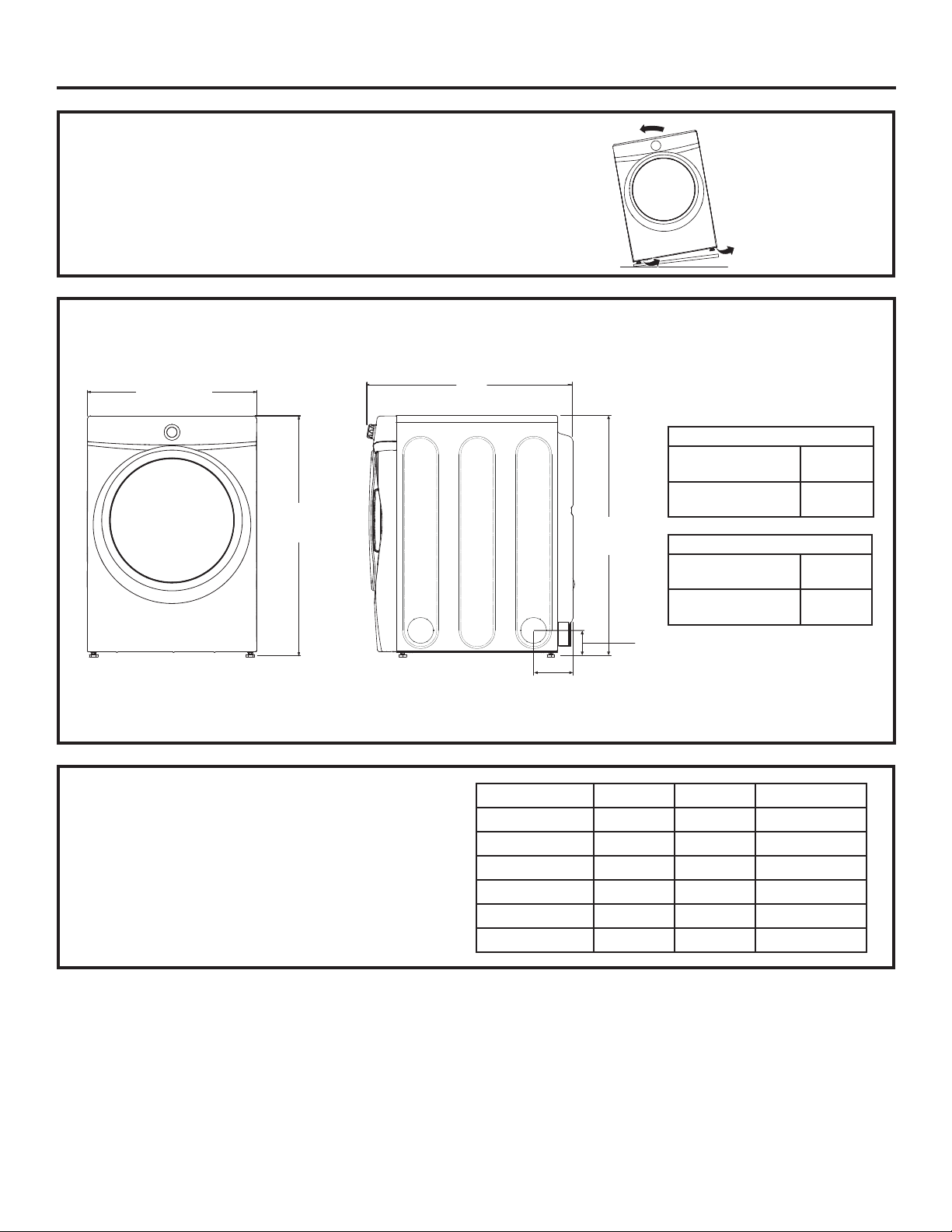
ROUGH-IN
DIMENSIONS
27”
(68.6 cm)
39 3/8”
(100 cm)
Front View
NOTE:
With Pedestal: 52 3/8” (133 cm)
Stacked: 79 5/8” (202.25 cm)
POWER CORDS:
GE Appliances strongly recommends the use of factory
specified parts. Select the power cord to fit your installation
requirements.
Order on-line at GEApplianceParts.com, 24 hours a day or
by phone at 800.626.2002 during normal business hours.
X
Side View
Part Number Type Length Amperage
X
32 3/16” (81.76 cm)
33” (83.80 cm)
39 3/8”
(100 cm)
4 1/2” (11.43 cm)
5 3/8” (13.65 cm)
4 3/8”
(11.11 cm)
Y
WX9X2 3-Prong 4 Feet 30
WX9X3 3-Prong 5 Feet 30
WX9X4 3-Prong 6 Feet 30
WX9X18 4-Prong 4 Feet 30
WX9X19 4-Prong 5 Feet 30
WX9X20 4-Prong 6 Feet 30
Y
7.0 cu. ft.
models
7.5 cu. ft.
models
7.0 cu. ft.
models
7.5 cu. ft.
models
2
Installation Instructions
REQUIREMENTS FOR ALCOVE OR
CLOSET INSTALLATION
WARNING
Keep flammable materials and vapors, such as gasoline,
away from dryer.
Place dryer at least 18” (46 cm) above the floor for a
garage installation.
Failure to do so can result in death, explosion, or fire.
•
The dryer MUST be vented to the outdoors. See
the EXHAUSTING THE DRYER section.
•
Minimum clearance between dryer cabinet and
adjacent walls or other surfaces is:
0” either side
3” front
3” rear
1” top
•
Consideration must be given to provide adequate
clearance for installation and service.
•
Closet doors must be louvered or otherwise
ventilated and have at least 60 square inches of
open area. If the closet contains both a washer
and a dryer, doors must contain a minimum of
120 square inches of open area.
NOTE: WHEN THE EXHAUST DUCT IS LOCATED IN
THE REAR OF THE DRYER, THE CONFIGURATION OF
THE DUCTING MAY REQUIRE GREATER THAN 3” OF
REAR CLEARANCE.
- Explosion Hazard
MINIMUM CLEARANCE OTHER THAN
ALCOVE OR CLOSET INSTALLATION
Minimum clearance to combustible surfaces and
for air opening are: 0” both sides; 3” rear; 1” top.
Consideration must be given to provide adequate
clearance for installation and service.
MOBILE OR MANUFACTURED HOME
INSTALLATION
• Installation must conform to the
MANUFACTURED HOME CONSTRUCTION AND
SAFETY STANDARD, TITLE 24, PART 32–80 or
Standard CAN/CSA-Z240 MH, or, when such
standard is not applicable, with AMERICAN
NATIONAL STANDARD FOR MOBILE HOME,
ANSI/NFPA NO. 501B.
•
The dryer MUST be vented to the outdoors. The
exhaust vent must be securely fastened to a
non-combustible portion of the mobile home.
•
The vent MUST NOT be terminated beneath a
mobile or manufactured home.
•
The vent duct material MUST BE METAL.
•
KIT 14-D346-33 MUST be used to attach the dryer
securely to the structure.
•
The vent MUST NOT be connected to any other
duct, vent or chimney.
•
Do not use sheet metal screws or other
fastening devices which extend into the interior
of the exhaust vent.
•
Provide an opening with a free area of at least
25 square inches for introduction of outside air
into the dryer room.
•
See the sections for electrical connection
information.
3
Installation Instructions
CONNECTING AN ELECTRIC DRYER
(Skip if your dryer already has a power cord attached)
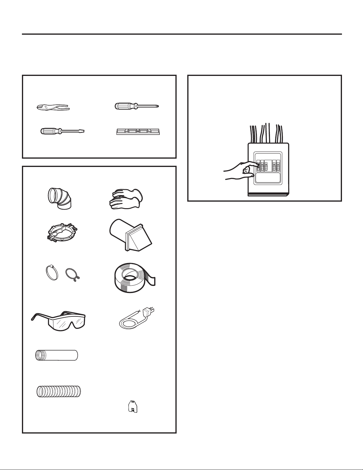
TOOLS YOU WILL NEED
Slip-joint pliers
Flat-blade crewdriver
Phillips screwdriver
Level
MATERIALS YOU WILL NEED
4” dia. metal elbow
3/4” strain relief
(UL recognized)
Gloves
Exhaust hood
Before making the electrical connection, turn off
the circuit breaker(s) or remove the dryer’s circuit
fuse(s) at the electrical box. Be sure the dryer cord
is unplugged from the wall.
NEVER LEAVE THE
ACCESS COVER OFF THE TERMINAL BLOCK.
4”duct
clamps (2) or
4”spring clamps (2)
Safety glasses
4” dia. metal duct
(recommended)
4” dia., UL-listed
flexible metal duct (if
needed)
Duct tape
Dryer power cord kit
(not provided with
dryer)
UL rated 120/240V,
30A with 3 or 4 prongs.
Identify the plug type
as per the house
receptacle before
purchasing line cord.
4” Cover Plate (Kit
WE49X22606)
4
Installation Instructions
ELECTRICAL CONNECTION
INFORMATION FOR ELECTRIC DRYERS
For electrical connections using a
power cord:
WARNING
Use a new UL-listed 240V 30 amp dryer power supply
cord with closed ring terminals or spade terminals with
upturned ends.
Use a UL-listed strain relief.
Disconnect power before making electrical
connections.
Connect neutral wire (white or center wire) to center
terminal.
Ground wire (green or bare wire) must be connected to
green ground connector.
Connect remaining two supply wires to remaining two
terminals.
Securely tighten all electrical connections.
Replace the terminal block cover.
Failure to do so can result in death, fire or electrical
shock.
- Fire Hazard
GROUNDING INSTRUCTIONS
For a grounded, cord-connected dryer: This dryer
must be grounded. In the event of a malfunction
or breakdown, grounding will reduce the risk
of electric shock by providing a path of least
resistance for electric current. This dryer uses a
cord having an equipment-grounding conductor
and a grounding plug. The plug must be plugged
into an appropriate outlet that is properly installed
and grounded in accordance with all local codes
and ordinances.
WARNING
can result in a risk of electrical shock. Check with a
qualified electrician, or service representative or
personnel, if you are in doubt as to whether the
appliance is properly grounded. DO NOT modify the
plug on the power supply cord. If it will not fit the
outlet, have a proper outlet installed by a qualified
electrician.
SAVE THESE INSTRUCTIONS
Improper connection of the
equipment-grounding conductor
ELECTRICAL CONNECTION
INFORMATION FOR ELECTRIC DRYERS
For direct wire connections:
WARNING
Use 10 gauge copper wire.
Use a UL-listed strain relief.
Disconnect power before making electrical
connections.
Connect neutral wire (white or center wire) to center
terminal.
Ground wire (green or bare wire) must be connected to
green ground connector.
Connect remaining two supply wires to remaining two
terminals.
Securely tighten all electrical connections.
Replace the terminal block cover.
Failure to do so can result in death, fire or electrical
shock.
- Fire Hazard
GROUNDING INSTRUCTIONS
For a permanently connected dryer: This
dryer must be connected to a grounded metal,
permanent wiring system, or an equipmentgrounding conductor must be run with the circuit
conductors and connected to the equipmentgrounding terminal on the appliance.
WARNING
can result in a risk of electrical shock. Check with a
qualified electrician, or service representative or
personnel, if you are in doubt as to whether the
appliance is properly grounded.
SAVE THESE INSTRUCTIONS
Improper connection of the
equipment-grounding conductor
5
Installation Instructions
CONNECTING AN ELECTRIC DRYER (cont.)
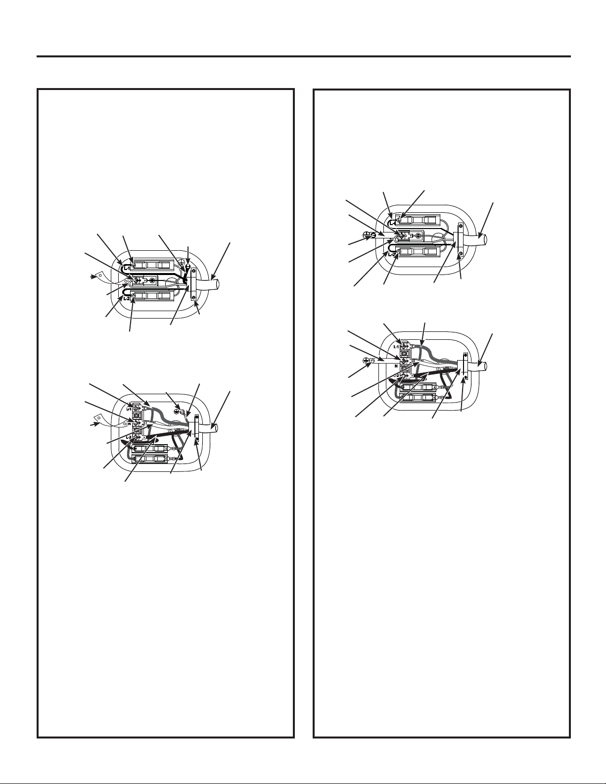
CONNECTING DRYER USING 4-WIRE
CONNECTION (MUST BE USED FOR
MOBILE HOME INSTALLATION)
NOTE: Since January 1, 1996, the National Electrical Code
requires that new constructions use a 4-wire connection
to an electric dryer. A 4-wire cord must also be used where
local codes do not permit grounding through the neutral.
3-wire connection is NOT for use on new construction.
Wire according to the terminal block illustration that
matches your dryer:
Hot Wire
Screw
Remove
ground strap
and discard.
Keep green
ground
screw.
Remove
ground strap
and discard.
Keep green
ground
screw.
Neutral
(white)
Screw
Screw
Neutral
(white)
Screw
Hot Wire
Hot Wire
Screw
Hot Wire
Green
Wire
Screw
Relocatre
green ground
screw here
3/4” UL
Recognized
Strain Relief
Relocatre
green ground
screw here
3/4” UL
Recognized
Strain Relief
Strain
Relief
Bracket
Green
Wire
Strain
Relief
Bracket
1. Turn off the circuit breaker(s) (30 amp) or remove the
dryer’s circuit fuse at the electrical box.
2. Be sure the dryer cord is unplugged from the wall
receptacle.
3. Remove the power cord cover located at the lower back.
4. Remove and discard ground strap. Keep the green
ground screw for Step 7.
5. Install 3/4 in. UL-recognized strain relief to power cord
entry hole. Bring power cord through strain relief.
6. Connect power cord as follows:
A. Connect the 2 hot lines to the outer screws of the
terminal block (marked L1 and L2).
B. Connect the neutral (white) line to the center of the
terminal block (marked N).
7. Attach ground wire of power cord with the green
ground screw (hole above strain relief bracket). Tighten
all terminal block screws (3) securely.
8. Properly secure power cord to strain relief.
9. Reinstall the cover.
NEVER LEAVE THE COVER OFF OF THE TERMINAL BLOCK.
4 #10 AWG
minimum
copper
conductors
or 120/240V
30A
power
supply cord
marked for use
with dryers
and provided
with closed
loop or spade
terminals with
upturned ends
(not supplied)
4 #10 AWG
minimum
copper
conductors
or 120/240V
30A
supply cord
marked for use
with dryers
and provided
with closed
loop or spade
terminals with
upturned ends
(not supplied)
kit
power
kit
CONNECTING DRYER USING 3-WIRE
CONNECTION
If required, by local code, install external ground (not
provided) to grounded metal, cold water pipe, or other
established ground determined by a qualified electrician.
Wire according to the terminal block illustration that
matches your dryer:
Hot Wire
Screw
Ground
Strap
Green
ground
screw
Neutral
(white)
Hot Wire
Screw
Ground
Strap
Green
ground
screw
Neutral
(white)
Screw
Screw
Screw
Hot
Wire
3-wire Connection
Not for use in Canada.
DO NOT use for Mobile Home Installations.
NOT for use on new construction.
NOT for use on recreational vehicles.
NOT for use in areas where local codes prohibit
grounding through the neutral conduction.
1. Turn off the circuit breaker(s) (30 amp) or remove the
dryer’s circuit fuse at the electrical box.
2. Be sure the dryer cord is unplugged from the wall
receptacle.
3. Remove the power cord cover located at the lower
back.
4. Install 3/4-in. UL-recognized strain relief to power cord
entry hole. Bring power cord through strain relief.
5. Connect power cord as follows:
A. Connect the 2 hot lines to the outer screws of the
terminal block (marked L1 and L2).
B. Connect the neutral (white) line to the center of the
terminal block (marked N).
6. Be sure ground strap is connected to neutral (center)
terminal of block and to green ground screw on cabinet
rear. Tighten all terminal block screws (3) securely.
7. Properly secure power cord to strain relief.
8. Reinstall the cover.
NEVER LEAVE THE COVER OFF OF THE TERMINAL BLOCK.
6
Screw
3/4” UL
Recognized
Strain Relief
Hot Wire
3/4” UL
Recognized
Strain Relief
Strain
Relief
Bracket
Strain
Relief
Bracket
3 #10 AWG
minimum copper
conductors or
120/240V 30A
power supply cord
kit marked for
use with dryers
and provided with
closed loop or
spade terminals
with upturned
ends (not supplied)
3 #10 AWG
minimum copper
conductors or
120/240V 30A
power supply cord
kit marked for
use with dryers
and provided with
closed loop or
spade terminals
with upturned
ends (not supplied)
Installation Instructions
EXHAUSTING THE DRYER
WARNING
This dryer MUST be vented to the outdoors.
Use only 4” rigid metal ducting for the home
exhaust duct.
Use only 4” rigid metal or UL-listed dryer transition
duct to connect the dryer to the home exhaust.
DO NOT use a plastic vent.
DO NOT exhaust into a chimney, kitchen exhaust,
gas vent, wall, ceiling, attic, crawl space, or
concealed space of a building.
DO NOT install a screen in or over the exhaust duct.
DO NOT install a booster fan in the exhaust duct.
DO NOT use duct longer than specified in the
exhaust length table.
Failure to follow these instructions can result in
death or fire.
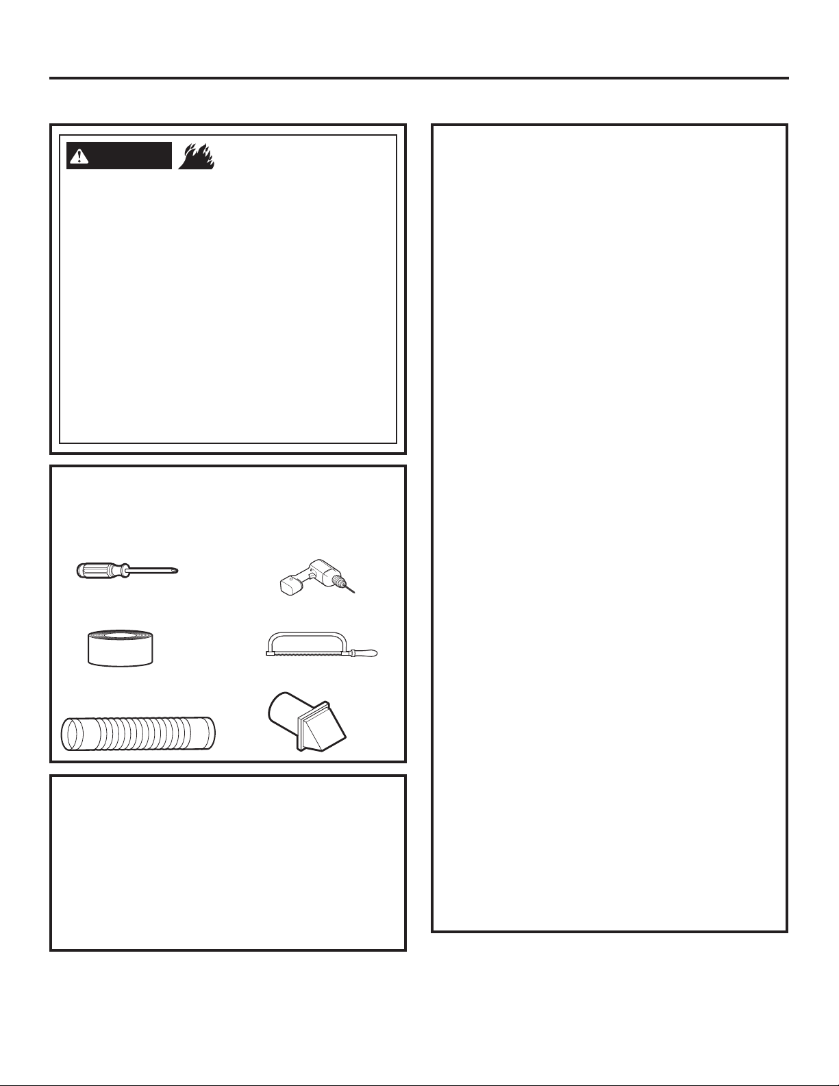
TOOLS AND MATERIALS YOU WILL
NEED TO INSTALL EXHAUST DUCT
Phillips-head
screwdriver
Duct tape or
duct clamp
Rigid or UL-listed flexible
metal 4” (10.2 cm) duct
PARTS AVAILABLE FROM GEAPPLIANCES.COM
OR LOCAL SERVICE ORGANIZATIONS
PM8X85
PM08X10085
WX08X10130
WE49X22606
Outdoor exhaust hood
8’ Flexible metal clothes dryer
transition duct with 2 clamps
4” Dryer exhaust clamp
Rear exhaust opening cover, for side
or bottom vented dryers
- Fire Hazard
Drill with 1/8” drill bit
(for bottom venting)
Hacksaw
Vent hood
CONNECTING THE DRYER TO HOUSE
VENT
RIGID METAL TRANSITION DUCT
•
For best drying performance, a rigid metal transition
duct is recommended.
•
Rigid metal transition ducts reduce the risk of crushing
and kinking.
UL-LISTED FLEXIBLE METAL CLOTHES DRYER
TRANSITION DUCT
If rigid metal cannot be used, then UL-LISTED flexible
•
metal clothes dryer transition duct (GE Appliances
part –
PM08X10085) can be used.
•
Never install transition duct in walls, ceilings, floors or
other enclosed spaces.
•
Total length of transition duct should not exceed
8’ (2.4 m).
• For many applications, installing elbows at both
the dryer and the wall is highly recommended (see
illustrations at right). Elbows allow the dryer to sit
close to the wall without kinking and/or crushing the
transition duct, maximizing drying performance.
•
Avoid resting the duct on sharp objects.
UL-LISTED FLEXIBLE METAL (FOIL-TYPE) TRANSITION
DUCT
In special installations, it may be necessary to connect
•
the dryer to the home exhaust vent using flexible metal
(foil-type) transition duct. UL–LISTED universal flexible
dryer transition duct (GE Appliances parts – PM8X73
or WX8X73) may be used ONLY in installations where
rigid metal or flexible metal transition ducting cannot
be used AND where a 4” diameter can be maintained
throughout the entire length of the transition duct.
•
In Canada and the United States, only transition ducts
that comply with “UL 2158A STANDARD FOR CLOTHES
DRYER TRANSITION DUCT” shall be used.
•
Avoid resting the duct on sharp objects.
•
For best drying performance:
1. Slide one end of the duct over the clothes dryer
2. Secure the duct with a clamp.
3. With the dryer in its permanent position, extend
4. Secure the duct to the exhaust pipe with the
outlet pipe.
the duct to its full length. Allow 2
overlap the exhaust pipe. Cut off and remove
excess duct. Keep the duct as straight as
possible for maximum airflow.
other clamp.
”
of duct to
7

Installation Instructions
EXHAUSTING THE DRYER (cont.)
• DO cut duct as short
as possible and install
straight into wall.
•
DO use elbows when
turns are necessary.
Elbows
• DO NOT bend
or collapse
ducting. Use
elbows if turns
are necessary.
• DO NOT use
excessive
exhaust
length. Cut
duct as short
as possible.
EXHAUST LENGTH
Using exhaust longer than specified length will:
• Increase the drying times and the energy cost.
• Reduce the dryer life.
• Accumulate lint, creating a potential fire
hazard.
The correct exhaust installation is YOUR
RESPONSIBILITY.
Problems due to incorrect installation are not
covered by the warranty.
• DO NOT
crush duct
against the
.
wall
• DO NOT
set dryer
on duct
The MAXIMUM ALLOWABLE length of the exhaust
system depends upon the type of duct, number of
turns, the type of exhaust hood (wall cap) and all
conditions noted on the chart.
• Internal elbows added for side or bottom vent
conversions must be included in the total elbow count.
• Any elbow greater than 45° should be treated as a
90° elbow.
• Two 45° elbows will be treated like one 90° elbow.
• For every additional 90° elbow, reduce the allowable
vent system length by 10 feet.
• When calculating the total vent system length, you
must add all the straight portions and elbows of the
system (including the transition duct).
.
No. of 90°
Elbows
0
1
2
3
4
EXHAUST LENGTH
FOR NORMAL VENT MODELS
RECOMMENDED MAXIMUM LENGTH
Exhaust Hood Types
Recommended
4" DIA.
4"
Rigid
Metal
90 Feet
60 Feet
45 Feet
35 Feet
25 Feet
4" DIA.
Use only for short
run installations
4" DIA.
Rigid
Metal
60 Feet
45 Feet
35 Feet
25 Feet
15 Feet
2-1/2"
8
No. of 90°
Elbows
0
1
2
3
4
5
EXHAUST LENGTH
FOR LONG VENT MODELS
RECOMMENDED MAXIMUM LENGTH
Exhaust Hood Types
Recommended
4" DIA.
4"
Rigid
Metal
200 Feet
185 Feet
175 Feet
165 Feet
155 Feet
145 Feet
4" DIA.
Use only for short
run installations
4" DIA.
2-1/2"
Rigid
Metal
175 Feet
165 Feet
155 Feet
145 Feet
135 Feet
125 Feet
 Loading...